EP3922508A1 - Isolierträgeranordnung für eine fahrleitung zum antrieb eines elektrofahrzeugs, insbesondere einer strassenbahn oder eines fahrleitungsomnibusses sowie zugehörige fahrleitung - Google Patents
Isolierträgeranordnung für eine fahrleitung zum antrieb eines elektrofahrzeugs, insbesondere einer strassenbahn oder eines fahrleitungsomnibusses sowie zugehörige fahrleitung Download PDFInfo
- Publication number
- EP3922508A1 EP3922508A1 EP20305632.0A EP20305632A EP3922508A1 EP 3922508 A1 EP3922508 A1 EP 3922508A1 EP 20305632 A EP20305632 A EP 20305632A EP 3922508 A1 EP3922508 A1 EP 3922508A1
- Authority
- EP
- European Patent Office
- Prior art keywords
- support assembly
- insulating support
- catenary
- insulator
- suspension device
- Prior art date
- Legal status (The legal status is an assumption and is not a legal conclusion. Google has not performed a legal analysis and makes no representation as to the accuracy of the status listed.)
- Pending
Links
- 239000000725 suspension Substances 0.000 claims abstract description 66
- 239000012212 insulator Substances 0.000 claims abstract description 63
- 210000000056 organ Anatomy 0.000 claims description 7
- 125000006850 spacer group Chemical group 0.000 claims description 4
- 230000000712 assembly Effects 0.000 description 4
- 238000000429 assembly Methods 0.000 description 4
- 230000035882 stress Effects 0.000 description 4
- 230000008878 coupling Effects 0.000 description 2
- 238000010168 coupling process Methods 0.000 description 2
- 238000005859 coupling reaction Methods 0.000 description 2
- 230000000694 effects Effects 0.000 description 2
- 230000000116 mitigating effect Effects 0.000 description 2
- 230000004048 modification Effects 0.000 description 2
- 238000012986 modification Methods 0.000 description 2
- 208000018672 Dilatation Diseases 0.000 description 1
- 230000009471 action Effects 0.000 description 1
- 230000002860 competitive effect Effects 0.000 description 1
- 230000008602 contraction Effects 0.000 description 1
- 230000010485 coping Effects 0.000 description 1
- 230000001186 cumulative effect Effects 0.000 description 1
- 239000012777 electrically insulating material Substances 0.000 description 1
- 238000009434 installation Methods 0.000 description 1
- 230000008092 positive effect Effects 0.000 description 1
- 238000010008 shearing Methods 0.000 description 1
- 230000008646 thermal stress Effects 0.000 description 1
Images


Classifications
-
- B—PERFORMING OPERATIONS; TRANSPORTING
- B60—VEHICLES IN GENERAL
- B60M—POWER SUPPLY LINES, AND DEVICES ALONG RAILS, FOR ELECTRICALLY- PROPELLED VEHICLES
- B60M1/00—Power supply lines for contact with collector on vehicle
- B60M1/12—Trolley lines; Accessories therefor
- B60M1/18—Section insulators; Section switches
-
- B—PERFORMING OPERATIONS; TRANSPORTING
- B60—VEHICLES IN GENERAL
- B60M—POWER SUPPLY LINES, AND DEVICES ALONG RAILS, FOR ELECTRICALLY- PROPELLED VEHICLES
- B60M1/00—Power supply lines for contact with collector on vehicle
- B60M1/12—Trolley lines; Accessories therefor
- B60M1/20—Arrangements for supporting or suspending trolley wires, e.g. from buildings
-
- B—PERFORMING OPERATIONS; TRANSPORTING
- B60—VEHICLES IN GENERAL
- B60M—POWER SUPPLY LINES, AND DEVICES ALONG RAILS, FOR ELECTRICALLY- PROPELLED VEHICLES
- B60M1/00—Power supply lines for contact with collector on vehicle
- B60M1/12—Trolley lines; Accessories therefor
- B60M1/16—Suspension insulators
Definitions
- the present invention relates in general to an insulating support assembly for applications in the field of transportation.
- the present invention concerns an insulating support assembly for a catenary adapted for powering an electrical vehicle, notably a tram or a trolleybus, and a catenary comprising such assembly.
- these overhead power lines comprise contact wires which carry the electric power transferred to the vehicles via an operative coupling with current collector equipment provided on-board of the vehicles themselves, such as pantographs, bow collectors, trolley poles, or similar devices.
- the contact wires are suspended at a certain height above the road level or above the railway tracks by connecting them to supporting poles which are installed along the various service routes of the transportation network.
- section insulators namely devices which are connected to the contact wire and are devised to electrically separate two electrical sections of the catenary, while allowing the smooth passage of pantographs with a continuous collection of current, such as in a crossover between two adjacent tracks, at curves or turnouts, et cetera.
- the section insulators are in turn mechanically connected to the supporting poles via the interposition of insulating support assemblies.
- the contact wires of catenaries are subject to thermal stresses which can lead to variations of their length due to contractions/dilatations; as a consequence, in known solutions, it has been noted that some parts of the whole assembly formed by connecting the various parts, namely the contact wire, the section insulator, the insulating supports and the cantilever beam of a supporting pole, have been subject to mechanical stresses leading to distortions if not to complete breakages, in particular of parts of the insulating support assemblies.
- the known supporting insulator assemblies are not easily adaptable to different types of section insulators used along the catenaries, and/or to different types of installing configurations.
- an object of the present invention is to provide an insulating support assembly which can be easily installed and allows reducing, with respect to known solutions, the difficulties of assembling with other components of the catenaries, and in particular with section insulators.
- Yet a further object of the present invention is to provide an insulating support assembly which can be used with different types of section insulators and/or different types of installing configurations, which is highly reliable, easy to realize and at competitive costs.
- the insulating support assembly according to the invention may comprise one or more of the following features, which may be combined in any technical feasible combination:
- a catenary adapted for powering an electrical vehicle characterized in that it comprises at least one insulating support assembly as above indicated, and in particular as described hereinafter and defined by the relevant appended claims.
- the catenary is notably a catenary of a tramway line or of a trolleybus line, but it can be also a catenary for powering any other suitable electrical vehicle on any type of suitable road, such as electrified road or highways and the like for supplying electrical cars, trucks, buses et cetera.
- transversal or transversally When the terms transversal or transversally are hereby used, they have to be understood as encompassing a direction non-parallel to the part(s) they refer to, and perpendicularity has to be considered a specific case of a transverse direction.
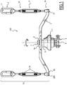
- Figure 1 illustrates an exemplary embodiment of an insulating support assembly according to the invention, therein indicated by the overall reference number 100.
- the insulating support assembly 100 comprises a base part, indicated in figure 2 by the cumulative reference number 105, which is adapted to connect the insulating support assembly 100 to a section insulator of a catenary.
- FIG 2 there is illustrated an exemplary embodiment of a section insulator, therein indicated by the reference number 112, which is connected to a contact wire 114 of a catenary 110, according to solutions per se known in the art or readily available to those skilled in the art.
- section insulators different from the one illustrated, can be used along a railway line and in function of the specific railway line.
- the catenary 110 is an aerial system used for feeding electric power to transiting electrical vehicles, for examples in railway lines, and comprises, among others, and according to solutions well known in the art and therefore also not described herein in details, the above indicated contact wire 114, a plurality of section insulators 112 connected to the wire 114 at different positions along the line, and a plurality of supporting poles which are installed along the line, spaced apart from each other.
- poles are usually provided with a cantilever beam for suspending the contact wire 114 over the tracks or the road service routes; in the example depicted in figure 2 , there is schematically illustrated a portion of a supporting pole, and in particular of its cantilever beam, indicated by the reference number 116.
- the insulating support assembly 100 further comprises at least:
- the suspension plate 2 is destined to be connected, namely hung, to a supporting pole 116, via suitable connecting means.
- the assembly 100 further comprises for example at least one arm, indicated in figure 1 by the overall number 15, which has a lower portion 16 connected to the suspension plate 2, and an opposite upper portion 17 which is adapted to connect the whole insulating support assembly 100 to a supporting pole 116 of the catenary 110, and in particular to its cantilever beam 116.
- the suspension plate 2 is connected to an upper part of and is movable relative to the suspension insulator 1.
- the suspension plate 2 is connected to an upper part of and is mounted rotatable around the reference axis Y relative to the suspension insulator 1.
- the base part 105 is configured to connect the insulating support assembly 100 to the section insulator 112 in such a manner that the section insulator 112 is movable relative to at least part of the insulating support assembly 100 itself.
- the base part 105 is configured to connect the insulating support assembly 100 to the section insulator 112 with the section insulator 112 which is allowed to translate relative to at least part of the insulating support assembly 100 along an axis X transversal with respect to the reference axis Y.
- the base part 105 comprises at least one connection organ or means 10 which is adapted to be fixedly connected to the section insulator 112 and comprises a slot 11 having at least a straight portion extending along the transversal axis X; in particular, in the example illustrated, the slot 11 is completely straight.
- Figure 1a better illustrates the support assembly 100 with its base part 105 assembled with a section insulator 112 equipped with a plate having a buttonhole 11, thus allowing an horizontal movement.
- the base part 105 comprises an extension portion 5 which is solidly connected at a lower part of the suspension insulator 1, and first connecting means 8, passing through the slot 11 and connecting the extension portion 5 with the connection plate 10.
- the extension portion 5 is in particular U-shaped.
- the first connecting means 8 comprise for example a screw and an associated nut; clearly, other equivalent connecting means can be used.
- connection plate 10 is inserted, at least partially, inside the U-shaped portion 5 fixed to the suspension insulator 1, with the connecting means 8 realizing their mutual sliding mechanical coupling; in case of a dimensional variations of the length of the contact wire 114, the section insulator 112 which is connected on one side with the contact wire 114 and on the other side with the connection plate 10, can translate, together with the connection plate 10, along the axis X in one direction or in the opposite direction relative to the remaining parts of the assembly 100.
- connection plate 10 for example two plates which are fixedly connected to the section insulator 112 positioned side by side to each other, and both connected to the same U-shaped portion 5 as above described; and/or it is possible to use one or more extension portions 5 having a different shape.
- the insulating support assembly 100 comprises: a bushing 6 which is fixed to an upper part of the suspension insulator 1 and passes through a central portion 2a of the suspension plate 2; a spacer 9 which is positioned around the bushing 6 and is interposed between an upper part of the suspension insulator 1 and the suspension plate 2; and second connecting means 7 which close the bushing 6 against the suspension insulator 1.
- the rotation of the suspension plate 2 is allowed thanks to the the fact that the thickness formed by the spacer 9 plus the central portion 2a is less than the connection seat of the bushing 6 so that there is a clearance for free rotation.
- the at least one arm 15 is connected at its lower portion 16 to the suspension plate 2 in an articulated manner, and in particular with the arm 15 which can rotate around an axis 200 transversal with respect to the suspension plate 2.
- the at least one arm 15 comprises adjusting means for adjusting its overall length.
- the at least one arm 15 comprises a first arm 15 and a second arm 15, substantially identical to each other, which are disposed substantially symmetric to each other with respect to the reference axis Y.
- first and second arms 15 are connected, each at a respective lower portion 16, to a corresponding extremity 2b, 2c of the suspension plate 2 and are both rotatable around an axis 200 transversal with respect to the suspension plate 2.
- each arm 15 comprises a hook or hook-shaped portion 3 which is configured to be connected to the supporting pole 116, e.g. its cantilever beam, and a turnbuckle 4 which comprises the lower portion 16 connected to the corresponding extremity 2b or 2c of the suspension plate 2, and an opposite upper portion 18 connected to the respective hook 3.
- the adjusting means comprises a first threaded connection 25 at the connection between each turnbuckle 4 with the suspension plate 2, and a second threaded connection at the connection between each turnbuckle 4 and the corresponding hook 3.
- the insulating supporting assembly 100 is suitable to be used in catenaries for feeding different types of electrical vehicles, travelling along different types of railway lines, in particular tramways or trolleybus lines, with different types of section insulators and/or with different installing configurations.
- the present invention encompasses also a catenary 110 adapted for powering an electrical vehicle, notably of a tramway or trolleybus line, characterized in that it comprises at least one insulating support assembly 100 as previously described, and in particular as defined in one or more of the appended claims.
- the assembly 100 according to the invention incorporates some degrees of freedom among parts of its own whole structure and also relative to the section insulator, thus avoiding, or at least properly mitigating, the undesired consequences of unexpected efforts caused by the thermal variations of the contact wire and/or by other external factors, such as the action of winds that can subject some parts of the assembly 100 to over stresses, e.g. fatigue stresses.
- the fact that the section insulator is allowed to freely translate along the reference axis X allows to properly face and adequately compensate the thermal variations of the contact wire 114; this positive effects is further enhanced by the fact that the supporting plate 2 can freely rotate around the axis Y, thus preventing or at least mitigating also the negative effects of a possible torque shearing exerted on the assembly 100.
- the mobility of the arms 15 relative to the suspension plate 2, their adjustable length, and the presence of the hooks 3, in addition to contributing to the above effects, and in synergy with the indicated freedom of translation along the axis X and rotation around the reference axis Y, allow to adapt easily the whole assembly 100 to different types of sections insulators, to different types of installing configurations, e.g. in curves and turnouts, and to quite easily absorb constructive mechanical tolerances and installing variations. Hence, also installation time and difficulties are reduced.
- the assembly 100 and related catenary 110 thus conceived are susceptible of modifications and variations, all of which are within the scope of the inventive concept as defined in particular by the appended claims; for example, some of the parts described can be differently shaped and/or connected in a way different from what above described, provided that such modifications would anyhow allow to carry the functionalities such parts are conceived to perform within the frame of the present invention.
Landscapes
- Engineering & Computer Science (AREA)
- Mechanical Engineering (AREA)
- Current-Collector Devices For Electrically Propelled Vehicles (AREA)
Priority Applications (4)
| Application Number | Priority Date | Filing Date | Title |
|---|---|---|---|
| EP20305632.0A EP3922508A1 (de) | 2020-06-10 | 2020-06-10 | Isolierträgeranordnung für eine fahrleitung zum antrieb eines elektrofahrzeugs, insbesondere einer strassenbahn oder eines fahrleitungsomnibusses sowie zugehörige fahrleitung |
| CA3120553A CA3120553C (en) | 2020-06-10 | 2021-06-02 | Insulating support assembly for a catenary adapted for powering an electrical vehicle, notably a tram or a trolleybus, and related catenary |
| US17/303,652 US20210387549A1 (en) | 2020-06-10 | 2021-06-03 | Insulating support assembly for a catenary adapted for powering an electrical vehicle, notably a tram or a trolleybus, and related catenary |
| MX2021006823A MX2021006823A (es) | 2020-06-10 | 2021-06-09 | Montaje de soporte aislante para catenaria adaptada para suministrar energia a vehiculo electrico, notablemente un tranvia o trolebus y catenaria relacionada. |
Applications Claiming Priority (1)
| Application Number | Priority Date | Filing Date | Title |
|---|---|---|---|
| EP20305632.0A EP3922508A1 (de) | 2020-06-10 | 2020-06-10 | Isolierträgeranordnung für eine fahrleitung zum antrieb eines elektrofahrzeugs, insbesondere einer strassenbahn oder eines fahrleitungsomnibusses sowie zugehörige fahrleitung |
Publications (1)
| Publication Number | Publication Date |
|---|---|
| EP3922508A1 true EP3922508A1 (de) | 2021-12-15 |
Family
ID=71575280
Family Applications (1)
| Application Number | Title | Priority Date | Filing Date |
|---|---|---|---|
| EP20305632.0A Pending EP3922508A1 (de) | 2020-06-10 | 2020-06-10 | Isolierträgeranordnung für eine fahrleitung zum antrieb eines elektrofahrzeugs, insbesondere einer strassenbahn oder eines fahrleitungsomnibusses sowie zugehörige fahrleitung |
Country Status (4)
| Country | Link |
|---|---|
| US (1) | US20210387549A1 (de) |
| EP (1) | EP3922508A1 (de) |
| CA (1) | CA3120553C (de) |
| MX (1) | MX2021006823A (de) |
Citations (4)
| Publication number | Priority date | Publication date | Assignee | Title |
|---|---|---|---|---|
| US716978A (en) * | 1902-08-25 | 1902-12-30 | Albert Anderson | Section-insulator. |
| US1962259A (en) * | 1931-06-26 | 1934-06-12 | Electric Railway Equipment Com | Section insulator |
| EP0475342A1 (de) * | 1990-09-13 | 1992-03-18 | Paul F. White | Einen Gleichstrom nicht übertragenden Streckentrenner |
| US5542511A (en) * | 1992-10-15 | 1996-08-06 | Kummler + Matter Ag Fahrleitungstechnik | Apparatus for suspending at least one current-carrying contact wire for current collectors of overhead line buses or trams |
-
2020
- 2020-06-10 EP EP20305632.0A patent/EP3922508A1/de active Pending
-
2021
- 2021-06-02 CA CA3120553A patent/CA3120553C/en active Active
- 2021-06-03 US US17/303,652 patent/US20210387549A1/en active Pending
- 2021-06-09 MX MX2021006823A patent/MX2021006823A/es unknown
Patent Citations (4)
| Publication number | Priority date | Publication date | Assignee | Title |
|---|---|---|---|---|
| US716978A (en) * | 1902-08-25 | 1902-12-30 | Albert Anderson | Section-insulator. |
| US1962259A (en) * | 1931-06-26 | 1934-06-12 | Electric Railway Equipment Com | Section insulator |
| EP0475342A1 (de) * | 1990-09-13 | 1992-03-18 | Paul F. White | Einen Gleichstrom nicht übertragenden Streckentrenner |
| US5542511A (en) * | 1992-10-15 | 1996-08-06 | Kummler + Matter Ag Fahrleitungstechnik | Apparatus for suspending at least one current-carrying contact wire for current collectors of overhead line buses or trams |
Also Published As
| Publication number | Publication date |
|---|---|
| CA3120553C (en) | 2023-10-17 |
| MX2021006823A (es) | 2022-11-10 |
| US20210387549A1 (en) | 2021-12-16 |
| CA3120553A1 (en) | 2021-12-10 |
Similar Documents
| Publication | Publication Date | Title |
|---|---|---|
| US4679672A (en) | Overhead electric traction system for railways | |
| JP4744605B2 (ja) | 剛体電車線用セクションインシュレータ | |
| KR20120027387A (ko) | 철도, 트롤리 및 지하철 라인의 라이브 케이블을 지지하기 위한 캔틸레버 | |
| CN108973782B (zh) | 城轨交通刚柔结合悬挂接触网 | |
| KR101746285B1 (ko) | 강체전차선용 지지클램프 | |
| US9845025B2 (en) | Rigid T-rail conductor system | |
| CN117500686A (zh) | 用于电驱动或混合电驱动的道路车辆的集电器 | |
| CA3120553C (en) | Insulating support assembly for a catenary adapted for powering an electrical vehicle, notably a tram or a trolleybus, and related catenary | |
| KR100869761B1 (ko) | 경전철용 전력공급장치 | |
| KR20130087778A (ko) | 신축이음장치 | |
| CN104627027A (zh) | DC750V~3kV柔性悬挂分段绝缘器 | |
| CN115742884B (zh) | 基于弹簧和阻尼电刷的刚性悬挂接触网系统 | |
| US4187934A (en) | Section insulator for catenary systems | |
| WO2015092413A1 (en) | Overhead electrification line cantilever assembly | |
| US4250982A (en) | Section insulator for catenary systems | |
| KR101900512B1 (ko) | 강체전차선 지지시스템 | |
| KR200377850Y1 (ko) | 전동차용 팬터그래프 | |
| EP3766729A1 (de) | Ausleger für hochgeschwindigkeitsoberleitung für verschiedene stromabnehmer | |
| CN207657613U (zh) | 双极刚性接触网式交通供电系统 | |
| EP4063185A1 (de) | Aufhängeklemme zum halten eines leitenden profils, starres oberleitungssystem und schienensystem mit einer solchen aufhängeklemme | |
| RU216789U1 (ru) | Поворотный подвес шинопровода контактной сети | |
| KR20010011797A (ko) | 경량전철 제3궤조 집전장치 | |
| CN109747429A (zh) | 双极刚性接触网式交通供电系统 | |
| KR20230053176A (ko) | 강체전차선 지지브래킷 | |
| Pande et al. | Light Weight Rigid OCS in Elevated Section of Delhi MRTS |
Legal Events
| Date | Code | Title | Description |
|---|---|---|---|
| PUAI | Public reference made under article 153(3) epc to a published international application that has entered the european phase |
Free format text: ORIGINAL CODE: 0009012 |
|
| STAA | Information on the status of an ep patent application or granted ep patent |
Free format text: STATUS: THE APPLICATION HAS BEEN PUBLISHED |
|
| STAA | Information on the status of an ep patent application or granted ep patent |
Free format text: STATUS: REQUEST FOR EXAMINATION WAS MADE |
|
| AK | Designated contracting states |
Kind code of ref document: A1 Designated state(s): AL AT BE BG CH CY CZ DE DK EE ES FI FR GB GR HR HU IE IS IT LI LT LU LV MC MK MT NL NO PL PT RO RS SE SI SK SM TR |
|
| B565 | Issuance of search results under rule 164(2) epc |
Effective date: 20201117 |
|
| 17P | Request for examination filed |
Effective date: 20211126 |
|
| RBV | Designated contracting states (corrected) |
Designated state(s): AL AT BE BG CH CY CZ DE DK EE ES FI FR GB GR HR HU IE IS IT LI LT LU LV MC MK MT NL NO PL PT RO RS SE SI SK SM TR |
|
| P01 | Opt-out of the competence of the unified patent court (upc) registered |
Effective date: 20230823 |
|
| RAP1 | Party data changed (applicant data changed or rights of an application transferred) |
Owner name: ALSTOM HOLDINGS |
|
| GRAP | Despatch of communication of intention to grant a patent |
Free format text: ORIGINAL CODE: EPIDOSNIGR1 |
|
| STAA | Information on the status of an ep patent application or granted ep patent |
Free format text: STATUS: GRANT OF PATENT IS INTENDED |