EP4062749A1 - Device and method for cultivating plants - Google Patents
Device and method for cultivating plants Download PDFInfo
- Publication number
- EP4062749A1 EP4062749A1 EP22162387.9A EP22162387A EP4062749A1 EP 4062749 A1 EP4062749 A1 EP 4062749A1 EP 22162387 A EP22162387 A EP 22162387A EP 4062749 A1 EP4062749 A1 EP 4062749A1
- Authority
- EP
- European Patent Office
- Prior art keywords
- planting
- plants
- container
- plant
- folds
- Prior art date
- Legal status (The legal status is an assumption and is not a legal conclusion. Google has not performed a legal analysis and makes no representation as to the accuracy of the status listed.)
- Granted
Links
- 238000000034 method Methods 0.000 title claims abstract description 18
- 235000015097 nutrients Nutrition 0.000 claims description 31
- 230000003698 anagen phase Effects 0.000 claims description 13
- 238000009313 farming Methods 0.000 claims description 8
- 230000012010 growth Effects 0.000 claims description 6
- 241000196324 Embryophyta Species 0.000 description 250
- XLYOFNOQVPJJNP-UHFFFAOYSA-N water Substances O XLYOFNOQVPJJNP-UHFFFAOYSA-N 0.000 description 15
- 238000003860 storage Methods 0.000 description 11
- 239000000758 substrate Substances 0.000 description 11
- 239000000203 mixture Substances 0.000 description 9
- 230000035784 germination Effects 0.000 description 7
- 238000004458 analytical method Methods 0.000 description 6
- 230000008878 coupling Effects 0.000 description 6
- 238000010168 coupling process Methods 0.000 description 6
- 238000005859 coupling reaction Methods 0.000 description 6
- 238000003306 harvesting Methods 0.000 description 6
- 238000003973 irrigation Methods 0.000 description 6
- 230000002262 irrigation Effects 0.000 description 6
- QVGXLLKOCUKJST-UHFFFAOYSA-N atomic oxygen Chemical compound [O] QVGXLLKOCUKJST-UHFFFAOYSA-N 0.000 description 3
- 238000012364 cultivation method Methods 0.000 description 3
- 238000005520 cutting process Methods 0.000 description 3
- 239000003501 hydroponics Substances 0.000 description 3
- 238000004519 manufacturing process Methods 0.000 description 3
- 229910052760 oxygen Inorganic materials 0.000 description 3
- 239000001301 oxygen Substances 0.000 description 3
- 206010040954 Skin wrinkling Diseases 0.000 description 2
- 238000004378 air conditioning Methods 0.000 description 2
- 230000000694 effects Effects 0.000 description 2
- 230000005611 electricity Effects 0.000 description 2
- 230000007613 environmental effect Effects 0.000 description 2
- 239000000835 fiber Substances 0.000 description 2
- 239000002609 medium Substances 0.000 description 2
- 239000007769 metal material Substances 0.000 description 2
- 239000005445 natural material Substances 0.000 description 2
- 230000008635 plant growth Effects 0.000 description 2
- 230000008092 positive effect Effects 0.000 description 2
- 235000013311 vegetables Nutrition 0.000 description 2
- 235000013162 Cocos nucifera Nutrition 0.000 description 1
- 244000060011 Cocos nucifera Species 0.000 description 1
- 206010061217 Infestation Diseases 0.000 description 1
- 241000607479 Yersinia pestis Species 0.000 description 1
- 238000006243 chemical reaction Methods 0.000 description 1
- QVFWZNCVPCJQOP-UHFFFAOYSA-N chloralodol Chemical compound CC(O)(C)CC(C)OC(O)C(Cl)(Cl)Cl QVFWZNCVPCJQOP-UHFFFAOYSA-N 0.000 description 1
- 239000011248 coating agent Substances 0.000 description 1
- 238000000576 coating method Methods 0.000 description 1
- 239000002131 composite material Substances 0.000 description 1
- 230000008602 contraction Effects 0.000 description 1
- 230000007797 corrosion Effects 0.000 description 1
- 238000005260 corrosion Methods 0.000 description 1
- 238000012272 crop production Methods 0.000 description 1
- 201000010099 disease Diseases 0.000 description 1
- 208000037265 diseases, disorders, signs and symptoms Diseases 0.000 description 1
- 238000005265 energy consumption Methods 0.000 description 1
- 238000004146 energy storage Methods 0.000 description 1
- 238000005516 engineering process Methods 0.000 description 1
- 239000004744 fabric Substances 0.000 description 1
- 239000012530 fluid Substances 0.000 description 1
- 235000012055 fruits and vegetables Nutrition 0.000 description 1
- 239000000417 fungicide Substances 0.000 description 1
- 239000001963 growth medium Substances 0.000 description 1
- 238000003780 insertion Methods 0.000 description 1
- 230000037431 insertion Effects 0.000 description 1
- 239000007788 liquid Substances 0.000 description 1
- 239000000463 material Substances 0.000 description 1
- 239000012528 membrane Substances 0.000 description 1
- 239000011490 mineral wool Substances 0.000 description 1
- 238000003032 molecular docking Methods 0.000 description 1
- 238000002663 nebulization Methods 0.000 description 1
- 239000006199 nebulizer Substances 0.000 description 1
- 239000000575 pesticide Substances 0.000 description 1
- 230000001105 regulatory effect Effects 0.000 description 1
- 239000000523 sample Substances 0.000 description 1
- 238000000926 separation method Methods 0.000 description 1
- 239000002689 soil Substances 0.000 description 1
- 230000009897 systematic effect Effects 0.000 description 1
- 244000045561 useful plants Species 0.000 description 1
- 238000005303 weighing Methods 0.000 description 1
- 230000037303 wrinkles Effects 0.000 description 1
Images


Classifications
-
- A—HUMAN NECESSITIES
- A01—AGRICULTURE; FORESTRY; ANIMAL HUSBANDRY; HUNTING; TRAPPING; FISHING
- A01G—HORTICULTURE; CULTIVATION OF VEGETABLES, FLOWERS, RICE, FRUIT, VINES, HOPS OR SEAWEED; FORESTRY; WATERING
- A01G9/00—Cultivation in receptacles, forcing-frames or greenhouses; Edging for beds, lawn or the like
- A01G9/02—Receptacles, e.g. flower-pots or boxes; Glasses for cultivating flowers
- A01G9/029—Receptacles for seedlings
-
- A—HUMAN NECESSITIES
- A01—AGRICULTURE; FORESTRY; ANIMAL HUSBANDRY; HUNTING; TRAPPING; FISHING
- A01G—HORTICULTURE; CULTIVATION OF VEGETABLES, FLOWERS, RICE, FRUIT, VINES, HOPS OR SEAWEED; FORESTRY; WATERING
- A01G31/00—Soilless cultivation, e.g. hydroponics
- A01G31/02—Special apparatus therefor
- A01G31/06—Hydroponic culture on racks or in stacked containers
-
- A—HUMAN NECESSITIES
- A01—AGRICULTURE; FORESTRY; ANIMAL HUSBANDRY; HUNTING; TRAPPING; FISHING
- A01G—HORTICULTURE; CULTIVATION OF VEGETABLES, FLOWERS, RICE, FRUIT, VINES, HOPS OR SEAWEED; FORESTRY; WATERING
- A01G9/00—Cultivation in receptacles, forcing-frames or greenhouses; Edging for beds, lawn or the like
- A01G9/02—Receptacles, e.g. flower-pots or boxes; Glasses for cultivating flowers
- A01G9/026—Foldable pots
-
- A—HUMAN NECESSITIES
- A01—AGRICULTURE; FORESTRY; ANIMAL HUSBANDRY; HUNTING; TRAPPING; FISHING
- A01G—HORTICULTURE; CULTIVATION OF VEGETABLES, FLOWERS, RICE, FRUIT, VINES, HOPS OR SEAWEED; FORESTRY; WATERING
- A01G9/00—Cultivation in receptacles, forcing-frames or greenhouses; Edging for beds, lawn or the like
- A01G9/02—Receptacles, e.g. flower-pots or boxes; Glasses for cultivating flowers
- A01G9/028—Multi-compartmented pots
-
- A—HUMAN NECESSITIES
- A01—AGRICULTURE; FORESTRY; ANIMAL HUSBANDRY; HUNTING; TRAPPING; FISHING
- A01G—HORTICULTURE; CULTIVATION OF VEGETABLES, FLOWERS, RICE, FRUIT, VINES, HOPS OR SEAWEED; FORESTRY; WATERING
- A01G9/00—Cultivation in receptacles, forcing-frames or greenhouses; Edging for beds, lawn or the like
- A01G9/02—Receptacles, e.g. flower-pots or boxes; Glasses for cultivating flowers
- A01G9/029—Receptacles for seedlings
- A01G9/0295—Units comprising two or more connected receptacles
Definitions
- the invention relates to a device for cultivating plants according to the preamble of claim 1 and a method for cultivating plants according to the preamble of claim 13.
- Such a device for cultivating plants can be used, for example, in vertical farming.
- the term vertical farming is understood to mean the cultivation of plants in closed rooms, on several floors one above the other under natural or artificial light.
- the plants are useful plants, such as fruit and vegetables, which are grown and harvested all year round. This is achieved in particular by artificial lighting, climate control and controlled nutrient supply.
- Hydroponics is a cultivation method in which the plants are not rooted in the ground, but in containers in which they are fixed with a substrate (e.g. coconut fiber or rockwool, etc.). Hydroponics is a form of hydroponics and is used for the systematic cultivation of crops and ornamental plants.
- a hydroponic system the roots of the plant are suspended in a mixture of water and nutrients dissolved in it.
- the plant is usually surrounded by a planting surface, such as a substrate or growing medium Plant container fixed.
- the plants are supplied with water and nutrients via a computer-controlled circulatory system.
- aeroponics is understood to mean a hydroponic cultivation method in which the plants are cultivated without a growing medium such as soil.
- the roots of the plant hang freely in the air below a planting area and are sprayed with a water-nutrient solution at regular intervals. This causes an increase in the oxygen content in the root system, which in turn has a positive effect on plant growth.
- the cuttings or young plants require little space in the plant containers in the early stages. It can thus be used in a planter many small plants. However, as the plants grow, the plant container becomes too small, so that the plants shade each other. By separating the plants, better exposure of the plants is achieved. Good lighting during the growth of the plants thus plays an important role, because with a good lighting the vegetable yield and plant yield can be maximized and the plants remain healthier. Due to the high energy requirement due to the artificial lighting, a denser cultivation method also uses less energy per plant. It is important that each photon of the artificial light hits a green area (leaves, etc.) of the plant.
- Automation is another important factor in vertical farming, because the automated production facilities can not only compensate for the lack of field workers, but fresh vegetables can also be grown and harvested 24 hours a day, 7 days a week on a small area in a cost-effective and resource-saving manner.
- transport robots In automated production, transport robots are used, which move the individual plant containers or plants within the rack storage area. However, robots are also used, which remove the individual plants from the planting containers and transplant them into larger containers. Such robots are already known from the prior art which move the plant containers through the system and remove individual plants from the plant containers.
- a mobile robot system delivers a first planting module and determines the density of the plants within the planting module. Depending on the determined density, individual plants are then removed from the first planting module with the help of a robot and placed in a second planting module. The planting modules are then brought back to the add-on shelf. The transplanting process can damage the roots of the plants.
- the U.S. 9,854,750 B2 discloses a method and system for automated commercial cultivation and production of plants in a controlled environment.
- the plants are artificially lit and supplied with nutrients and are in planting trays, which are arranged in a container. Depending on the growth stage and plant size, the individual plants are transplanted automatically.
- the very high power consumption represents the greatest cost and environmental factor.
- the power consumption is mainly caused by the lighting and air conditioning. Both factors depend on the light area.
- the automated separation of the plants or the automated transplanting of the plants is very complex. Some of the plants are firmly rooted in the planting area and are roughly torn out by the robot when separated and damaged as a result.
- a device for growing plants is already known, in which a foldable planting surface is used, which is located on the ground and is designed to be extendable.
- the planting area can be adjusted to the respective plant size by pulling it apart. By pulling apart, however, the extent of the planting area is constantly changing, so that different planting area sizes are available for the cultivation of the plants.
- Such stationary planting areas are difficult to illuminate, the lighting being complex and associated with high energy costs.
- the invention is characterized by the technical teaching of claims 1, 13 and 15 in order to solve the task at hand.
- An essential feature according to claim 1 is that the device for growing plants is designed as a plant container, in the interior of which a foldable plant area can be arranged.
- the device according to the invention is preferably designed as a transportable planting container which has a foldable planting surface which is adapted to the growth phase of the plants. This has the advantage of increasing the average number of plants per m 2 of light, which saves on electricity costs.
- the foldable planting area can be arranged in the interior of the plant container. This means that the planting area is either fixed in the interior or can be inserted into the planting container or removed from the planting container.
- the device is designed as a transportable plant container that is open on one side and delimited by surrounding walls at the edges, in the bottom space of which a nutrient solution for growing the plants is arranged, the bottom space being at least partially covered at the top by the planting area.
- the foldable planting area is designed as an elastic bellows.
- bellows is understood to mean a planting surface which is designed as an elastic, extendable surface lying in folds.
- the bellows can be made of plastic, fabric or another foldable material, for example.
- a high level of dimensional stability is achieved by arranging the folded surfaces in a row and because of the continuously connected pleat tips.
- the foldable planting surface consists of individual panels which are connected to one another by means of an articulated connection.
- the foldable planting surface is preferably folded into the planting container.
- the foldable planting surface has folds and a horizontal web. There is thus a web between the two folds, which is connected to the two adjacent folds via articulated connections.
- the folds and the web are preferably designed in the form of plates.
- the horizontal bar is thus a plate-shaped planting bar, which preferably has the openings for the plants, with the plants lying flat. The two adjacent folds give the young plants additional lateral support.
- the planting surface is gradually pulled apart like an accordion, which means that the angle between the individual folds widens. This gives the plants more space on the side and can be better exposed to light.
- the plants are simultaneously lifted vertically. As a result, the most optimal position for the roots of the plant relative to the bottom of the plant container, in which the mixture of water, nutrients and oxygen is located, is always achieved.
- the planting area is preferably designed as a module which can be inserted into the planting container and removed again.
- the module consists either of the bellows with several elastic folds or of several foldable panels, which are connected to each other by articulated connections.
- the modules of the planting areas can be manipulated by a robot.
- a 6-axis robot with a gripper can remove the modules from the planter and place them in another planter. Or the module is lifted out of the plant container and moved by a rope gripper.
- a tray stacker can also be used, for example.
- the plants require relatively little space. This means that several modular planting areas are used in the folded state together with the plants in the planter. The space inside the planter can thus be optimally utilized. As a result, more plants can be cultivated per planter with the same light source and the same air conditioning.
- a substrate pad with the respective seed of the plant is preferably inserted into the openings of the planting area.
- the planting area has an opening with a basket-like receptacle.
- the fold valleys extend deep into the planting container. This allows the substrate pad to come into contact with the mixture of water, air and nutrients.
- the plants are still very small in the initial phase and require little space. Especially if the plant is initially only available as a seed, which is in a pad of substrate.
- two modules are removed from the plant container and placed in another plant container.
- the remaining folded planting areas are pulled apart by a certain length, increasing the angle between the folds. The folds open and the plants are lifted in the vertical direction.
- another planting area is removed from the planting container and placed in another planting container.
- the remaining, folded planting areas are pulled further apart. 10 days later, another planting area is removed from the planting container and placed in another planting container.
- the folded planting areas are now completely pulled apart so that they create a flat, horizontal surface.
- the horizontal surface represents the maximum distance between the planting surface and the bottom of the planter. Since the roots have grown continuously, there is still contact with the mixture of water, nutrients and oxygen at the bottom of the planter.
- the modular, foldable planting areas have a decisive advantage over the prior art. During the growth phase, the plants always remain in the same opening in the planting area. The roots are therefore not damaged when moving the modular planting areas. In contrast to this, in the prior art, the individual plant is removed from the planting area with the aid of a robot and transferred to a new planting area.
- the planting area preferably consists of individual, foldable panels.
- the panels can either be folded independently or are connected to one another via a joint.
- the at least one articulation is arranged between the two adjoining panels either in the region of the valley of the folds or in the region of the peak of the folds. Thanks to the articulated connection, the two panels can be opened from a very small angle (e.g. 10°) to a very large angle (e.g. 180°).
- the openings or recesses for the individual plants are located either in the fold valley, fold peak or in the plate surface of the planting area.
- the planting surface is the growth medium for the plants, with which the plants are fixed within the planter.
- the planting area consists, for example, of a plastic, a fiber composite material, a metal material or a natural substance.
- the planting area has a receptacle for the automated pulling apart and pushing together.
- This can be a recess or eyelet, for example, which can be easily recognized and gripped by a robot.
- the planting area has its own coupling, to which the robot docks in order to close the planting area move.
- the planting area can also be pulled apart and pulled together by hand.
- the plant container consists, for example, of a (food-safe) plastic or a metal or natural material.
- the container should be UV-resistant and have corrosion protection. Furthermore, the container should be washable so that it can be used several times.
- the planting container has a guide device which interacts with the foldable planting surface.
- the guide device is designed either steplessly or stepwise.
- the guide device can be designed as a toothed rack. There is then either a toothed rack on one side of the plant container and on the opposite side only a smooth guide rail. The foldable planting area can then be locked on one side. It is also possible that there is a toothed rack on both sides of the plant container, in the recesses of which individual links or a rod of the foldable plant surface can be inserted.
- the foldable planting surface is detachably arranged in the planting container by the guide device.
- the guide device here has two tasks. On the one hand, the planting area is positioned in the vertical direction within the plant container. The height of the guiding device within the plant container is selected in such a way that the plant area can be pulled apart, with the roots of the plants preferably not having any contact with the plant container bottom. On the other hand, the guiding device allows the foldable planting surface to be pulled apart and folded in step-like or step-like manner.
- the guide device extends in the direction of the longitudinal axis of the plant container on the two side walls.
- at least two guide devices may be arranged at 90° to the longitudinal axis of the plant container.
- the guide devices thus form a kind of grid inside the plant container, which guides the foldable plant area.
- the plant container has at least one receptacle with which it can be easily gripped, picked up and put down by the robot.
- the receptacle can, for example, be a specific area or a recess in the floor area of the plant container, which can easily be driven under by the load handling device of the transport robot.
- the plant container according to the invention is preferably used in a rack storage facility (e.g. shelving rack storage facility), with the plant containers being located in rack storage locations arranged vertically one above the other.
- the plant containers are moved within the rack storage area with a transport robot.
- the transport robot is, for example, like the rail-bound transport robot with lifting platform according to the DE 10 2017 121 638 A1 designed by the same applicant, to which reference is made in full. Furthermore, a transport robot according to the DE 10 2018 109 495 A1 are used, to which reference is also made in full.
- the transport robot is in two parts.
- the first part of the transport robot is designed as a chassis for horizontal travel on rails and the second part has a lifting platform with an integrated load handling device.
- the transport robot is preferably arranged to be mobile on the hall ceiling. This means that the storage area underneath can be used for other purposes.
- the storage and retrieval of the plant containers is carried out with a load handling device, which has, for example, two extendable tines that drive under the container and load it precisely onto the transport robot using a toothed belt.
- the folds of the foldable planting surface have a reflective surface.
- the reflective surfaces can either have a special coating or a special color, through which the light is reflected particularly well or redirected in the direction of the plants.
- the plant container also has at least one media coupling, via which energy and/or data/signals and/or nutrients, water or air are supplied.
- Radio technology for example (e.g. Bluetooth, ZigBee, WLAN, LTE, ISM, narrowband iot, lora etc.)
- the planting container with the plants is preferably checked at least once every 24 hours.
- the check can be carried out, for example, in an analysis line.
- the plant container is removed from the shelf and taken to an analysis line.
- the control is carried out optically with a camera and based on the weight with a scale.
- a wide variety of data on water quality can be recorded by a sensor probe. The data obtained is stored and used to optimize the system. After the check, a decision is made as to whether the plants still have enough space inside the plant container, or whether at least one module must be removed from the plant container and the remaining modules pulled apart.
- the analysis can also be carried out on the transport robot.
- the transport robot has a camera and/or a weighing device and/or a measuring device, with which the condition of the plants and the fill level of the plant container can be determined. This data could also be sent to the robot from the container itself.
- the transport robot decides whether the planting container is to be taken to a refilling station, for example, a module is to be removed from the planting container, or whether the foldable planting area is to be pulled further apart.
- the transport robot can also have a camera with which an infestation with pests or a disease on the plant is detected.
- the analysis line preferably has a docking station to which the planting container is docked with its media coupling in order to refill energy and/or nutrients, water or air.
- the data can be read from the plant container.
- the energy transfer could also be wireless.
- the plant container can also have its own energy store, which stores and provides energy for, for example, irrigation or for the measuring devices.
- the energy store is charged, for example, inductively in the analysis line or by the media coupling at the storage location.
- a passive irrigation system is the wick system, in which the individual plants are arranged in a substrate and are connected to the nutrient solution underneath via a wick. Through the capillary effect of the wick, the water and the nutrients are carried to the plant.
- An irrigation system is irrigation using the nutrient film technique NFT.
- NFT nutrient film technique
- the ultrasonic nebulizer has a piezoceramic element (membrane) which is set in motion by applying an electrical AC voltage. This vibration spreads to the surrounding water or the nutrient solution and releases small droplets from the surface.
- a hydro-aero system in the bottom area of the plant container, which consists of a water reservoir and an ultrasonic atomizer.
- a water reservoir for example, there is a 3 cm high water-nutrient mixture and above it a mist-air mixture, which is generated by the ultrasonic atomizer.
- the supply of nutrients and the watering for each individual plant container are preferably regulated separately.
- the amount of nutrients or fluid to be refilled is determined either in the analysis line or by the measuring device arranged in the plant container.
- Protection is also claimed for a method for cultivating plants, in which at least one planting surface has a plurality of folds parallel to one another and in the planting surface there are a large number of spaced-apart openings into which the plants can be inserted, the device being used as a planting container is formed, in the interior of which a foldable planting surface is arranged, which can be folded up and/or extended in the horizontal direction.
- the plant container according to the invention is used for cultivating plants in vertical farming.
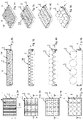
- Figure 1a shows the rectangular plant container 1, which is preferably made of plastic and is designed to be liquid and light-tight.
- a foldable plant area 2 which consists of individual folds 4 .
- the folds 4 are connected to one another and together form an elastic bellows.
- the opening 9 is designed so large that the growing plant 3 is held and fixed by the planting area 2.
- the receptacle 10 is designed, for example, like a basket or grid, so that the substrate in the receptacle 10 is in sufficient contact with the nutrient solution 15 below the planting area 2 through the grid openings.
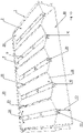
- Figure 1b shows the plant container 1 with the planting area 2, which has been pulled apart in the direction of the arrow 11. The distance between the folds 4 has thus been increased, so that the grown plants 3 have more space and light. By pulling the planting area is simultaneously raised in the direction of arrow 12, whereby the distance 13 between the planting area 2 and the container bottom 16 increases.
- Figure 1c shows the plant container 1 with a plant area 2 pulled further apart. The distance 13 has increased further. This gives the roots of the plants 3 more space below the planting area 2.
- Figure 1d shows the plant container 1 with the maximum extended or expanded planting area 2.
- the plants 3 are no longer between the folds 4, but lie on a flat planting area 2 and are therefore easy to harvest.
- the Figures 2a, 3a, 4a and 5a each show a top view of the plant container 1. From the top views it can be seen that the planting area 2 is designed as a module 14, and according to FIG Figure 2a a total of five modules 14 are arranged within the plant container 1. As the plants 3 grow, more and more modules 14 are removed from the planting container 1 and the remaining planted areas 2 in the planting container 1 are pulled further apart. This will be with the Figure 3a shown, in which there are only three modules 14 in the plant container 1. According to the Figure 4a there are only two modules 14 in the plant container 1 and Figure 5a shows a plant container 1 with only one module 14 with a completely expanded planting area 2.
- the Figures 2b, 3b, 4b and 5b correspond to the Figures 1a, 1b, 1c and 1d . They show the plant containers 1 during the growth phase of the plants 3.
- the plant container 1 is shown in perspective during the growth phase of the plants 3.
- the perspective views show that the plants 3 are growing and therefore require more and more space.
- the necessary space is achieved by pulling the foldable planting area 2 apart.
- individual, modular planting areas 3 can be removed from the planting container 1 and converted into a new planting container 1 .
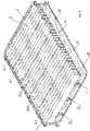
- FIG 6 shows the plant container 1 in a sectional view.
- a module 14 consists of five webs 20, which are connected to the adjacent Folds 4 are connected.
- the webs 20 have the receptacles 10 for the plants 3 .
- the receptacles 10 are designed in the manner of a basket, so that the individual roots 21 of the plants 3 extend through the basket-like receptacle 10 and are in contact with the nutrient solution 15 which is located in the area of the bottom space 30 .
- the plants 3 are thus in each case between two folds 4 which fix the plants 3 in place.
- the folds 4 preferably have a reflective surface with which the light is reflected in a targeted manner onto the plants 3 .
- the plant container 1 has lateral guide devices 7 for the foldable plant area 2 .
- the guide device 7 is according to figure 6 designed as a toothed rack, in which a rod 19 of the planting area 2 engages.
- the guide device 7 allows the foldable planting area 2 to be pulled apart and pushed together in stages, with the position of the planting area 2 being fixed when the rod 19 engages between two teeth of the toothed rack.
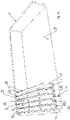
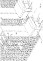
- figure 7 shows the plant container 1 with a total of three modules 14 ', 14 "and 14 ′′′. Compared to the representation of the figure 6 A total of two modules 14 were removed from the plant container 1. This creates additional space within the plant container 1, so that the remaining modules 14', 14" and 14′′′ can be pulled apart. The plants 3 thus have more space. By pulling the planting areas 3 apart in the direction of the arrow 12, the distance 13 between the container floor 16 and the openings 10 of the planting area 2. The floor space 30 is thus enlarged.
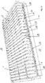
- FIG 8 a plant container with only one module 14' is shown.
- the planting area 2 of the module 14' is completely spread out.
- the webs 20 and the adjoining folds 4 form a plane on which the plants 3 that are ready for harvest lie.
- the planting area 3 preferably has a plurality of rods 19 which engage in the rack-like guide device 7 . By engaging or latching the rods 19 in the guide device 7 an unwanted contraction of the planting area 3 is prevented.
- At least one watering device 17 is located in the floor space 30 in the area of the container floor 15.
- the watering device 17 is designed as an ultrasonic atomizer and generates a mixture of air and the nutrient solution 15 below the planting area 2, which is absorbed by the roots 21 of the plants 3.
- the energy for the watering device 17 comes from an energy store 18.
- the energy store 18 is charged with energy via a media coupling 18.
- the plant container 1 is self-sufficient due to the energy store 18 . This means that the plant container 1 only needs one light source while the plants 3 are being reared.
- the plant container 1 can also have several media couplings 18, via which the nutrient solution is refilled, for example. Furthermore, it is possible for the plant container 1 to have its own measuring device, with which, for example, the fill level of the nutrient solution, the temperature, the light intensity or the like is measured.
- the planting container 1 is shown with a foldable planting area 2, which is designed as a module 14.
- the planting area 2 consists of individual folds 4, which are connected to webs 19 via articulated connections. Two folds 4 and a web 19 together form a U-shaped row of plants.
- the module 14 has a total of five rows of plants 24 arranged next to one another.
- the rows of plants 24 are spaced apart from the bottom 16 of the container by the lateral guide devices 7 of the plant container 1 . Due to the distance, the roots 21 of the plants 3 can be optimally supplied with a mixture of air and the nutrient solution.
- the planting area 3 has individual articulated connections 23 which connect two folds 4 to one another.
- the articulated connections 23 can have additional slots through which the rods 19 for the guide device 7 can be inserted.
- Each fold tip 6 preferably has an insertion 2 so that the guidance of the planting area 3 can be individually adjusted.
- figure 11 shows the plant container 1 with several modules 14, as used for example in the germination phase of the plants 3.
- the figure 11 are located many rows of plants 24 next to each other in the plant container 1.
- many plants 3 can be illuminated with the same light source.
- the space within the plant container 1 is thus optimally utilized and the electricity costs for lighting the plants can be saved.
- the plants 3 are located deep in the plant container 3 in this state of the plant rows 24 , so that the plants 3 are sufficiently in contact with the nutrient solution 15 located on the container bottom 16 .
- the folds 4 of the planting area 3 are designed as plates 29 which are connected to one another by at least one articulated connection 23 .
- figure 12 shows the plant container 1 with a plant area 3 partially pulled apart. Two folds 4 and the web 20 lying between them together form a row 24 of plants. The first fold 4 and second fold 4 are partially opened by an angle 25 . The rows of plants 24 are connected to one another via articulated connections 23 .
- figure 13 shows the planting container 1 with a planting area 3 completely pulled apart.
- the folds 4 of the rows of plants 23 are now open at an angle 26 .
- the angle 25 is greater than the angle 25 according to the figure 12 .
- the transport robot 8 consists essentially of an approximately rectangular frame in which a central recess is arranged, which is delimited on both sides by two opposite lifting devices.
- a lifting platform can be raised and lowered from the middle recess.
- Load handling devices are arranged on the lifting platform, which are designed as two spaced-apart telescopic arms that can be moved in and out.
- the plant containers 3 are reached under on the underside and pulled onto the surface of the lifting platform.
- the lifting platform can be raised by the lifting devices, so that the plant container 1 is then located in the interior of the transport robot 8 and the transport robot 8 moves to other points on the rail 28 with the lifting platform raised.
- the module 14 of the foldable planting area 3 is inserted into or removed from the planting container 1 with the transport robot 8 .
- the transport robot has a special gripping device for this purpose.
- the plant container 1 according to the invention With the plant container 1 according to the invention with the foldable planting area 3, it is now possible to illuminate more plants 3 on the same area with one light source. This is achieved by the planting surface 3 that can be pulled apart, the number of rows of plants 24 being adaptable to the respective state of growth and space requirements of the plants 3 . Since the plants 3 are always in the same opening of the planting area 3 during the entire growth phase, the roots 21 are not damaged. In addition, several plants 3 can be automatically removed from the planting container 3 at once and transferred to a new planting container 3 .
- phase #1 the seeds for the plants 3 are in a substrate in the respective receptacles 10 of the planting area 2.
- the plant container 2 does not yet have any nutrient solution 16 or the like. In this state, the plant containers 2 can be stored for a longer period of time.
- the seeds of the plants 3 are activated by adding water or nutrient solution 15 as required.
- Phase #2 shows the germination phase of the plants 3.
- a nutrient solution 15 is located on the container bottom 16, which is at least partially in contact with the substrate or the plant 3 in the receptacle 10 of the planting area 2.
- the plant containers 1 can now be placed in a shelf warehouse during the growth phase.
- Phase #3 shows the growth phases of the plants 3, with a total of five modules 14 of the planting area 2 still being located in the first, left-hand planting container 1 due to the small plant size. Due to the growth of the plants 3, the space requirement in the planting container 1 is increasing, so that individual modules 14 are removed from the planting container 1 and the remaining modules 14 are pulled apart. During the growth phase, the plants 3 in the planting area 2 are analyzed and, if necessary, nutrient solution 16 is refilled or individual Planting areas 2 removed from the planting container 1. There are therefore only two modules 14 in the middle planting container 1 . The right planting container 1 has only one module 14 . The planting area 2 of the right plant container 1 is completely expanded. The plants 3 that are ready for harvest are now lying on the planting area 1 .
- Phase #4 is the processing phase in which the plants 3 are harvested. After the plants 3 have been harvested, the plant containers 1 are washed and fitted with new planting areas 2 . The plant containers 1 are then put back into storage (cf. phase #1).
Landscapes
- Life Sciences & Earth Sciences (AREA)
- Environmental Sciences (AREA)
- Cultivation Receptacles Or Flower-Pots, Or Pots For Seedlings (AREA)
Abstract
Vorrichtung und Verfahren zur Aufzucht von Pflanzen (3), bestehend aus mindestens einer Pflanzfläche (2), welche mehrere zueinander parallele Falten (4) aufweist, wobei in der Pflanzfläche (2) eine Vielzahl von im Abstand voneinander angeordneten Öffnungen (9) vorhanden sind, in welche die Pflanzen (3) einsetzbar sind, wobei die Vorrichtung als Pflanzbehälter (1) ausgebildet ist, in dessen Innenraum eine faltbare Pflanzfläche (2) angeordnet ist.Device and method for cultivating plants (3), consisting of at least one planting surface (2) which has a plurality of parallel folds (4), the planting surface (2) having a large number of spaced-apart openings (9). , into which the plants (3) can be inserted, the device being designed as a plant container (1) in the interior of which a foldable plant surface (2) is arranged.
Description
Die Erfindung betrifft eine Vorrichtung zur Aufzucht von Pflanzen nach dem Oberbegriff des Anspruches 1 und ein Verfahren zur Aufzucht von Pflanzen nach dem Oberbegriff des Anspruches 13.The invention relates to a device for cultivating plants according to the preamble of
Ein solche Vorrichtung zur Aufzucht von Pflanzen kann beispielsweise bei einer vertikalen Landwirtschaft eingesetzt werden. Unter dem Begriff vertikale Landwirtschaft (engl. vertical farming) wird die Kultivierung von Pflanzen in geschlossenen Räumen, auf mehreren übereinanderliegenden Etagen unter natürlichem bzw. künstlichem Licht verstanden. Bei den Pflanzen handelt es sich um Nutzpflanzen, wie beispielsweise Obst und Gemüse, welche ganzjährig angebaut und geerntet werden. Dies wird insbesondere durch eine künstliche Beleuchtung, eine Klimasteuerung und eine gesteuerte Nährstoffversorgung erreicht.Such a device for cultivating plants can be used, for example, in vertical farming. The term vertical farming is understood to mean the cultivation of plants in closed rooms, on several floors one above the other under natural or artificial light. The plants are useful plants, such as fruit and vegetables, which are grown and harvested all year round. This is achieved in particular by artificial lighting, climate control and controlled nutrient supply.
Die vertikale Landwirtschaft benötigt deutlich weniger Grundfläche, da die Pflanzen in mehrstöckigen Gebäuden (sogenannten Farmscrapers) angebaut werden, welche nahe an Ballungsgebieten der Städte errichtet werden. Dadurch werden lange Transportwege von den Anbaugebieten zu den Verbrauchern vermieden. Weitere Vorteile sind die Steigerung der Nutzpflanzenproduktion, der Schutz vor Witterungseinflüssen, ein ressourcenschonender Anbau, die Wassereinsparung durch geschlossene Wasserkreisläufe, sowie die Nutzung von erneuerbaren Energien. Auf den Einsatz von Pestiziden und Fungiziden kann aufgrund der fehlenden Umwelteinflüsse ebenfalls verzichtet werden.Vertical farming requires significantly less floor space because the crops are grown in multi-story buildings (so-called farm scrapers) that are built close to metropolitan areas. This avoids long transport routes from the growing areas to the consumers. Further advantages are the increase in crop production, protection against the effects of the weather, resource-saving cultivation, water savings through closed water circuits and the use of renewable energies. The use of pesticides and fungicides can also be dispensed with due to the lack of environmental influences.
Bei der Hydrokultur handelt es sich um eine Anbaumethode, bei der die Pflanzen nicht in der Erde wurzeln, sondern in Behältern, in denen sie mit einem Substrat (bspw. Kokosfaser oder Steinwolle etc.) fixiert werden. Hydroponik ist eine Form der Hydrokultur und wird zum planmäßigen Anbau von Nutzpflanzen und Zierpflanzen eingesetzt. Bei einem hydroponischen System hängen die Wurzeln der Pflanze in einem Gemisch aus Wasser und darin gelösten Nährstoffen. Die Pflanze wird in der Regel durch eine Pflanzfläche, wie z.B. ein Substrat oder ein Wachstumsmedium im Pflanzenbehälter fixiert. Die Versorgung der Pflanzen mit Wasser und Nährstoffen erfolgt über ein computergesteuertes Kreislaufsystem.Hydroponics is a cultivation method in which the plants are not rooted in the ground, but in containers in which they are fixed with a substrate (e.g. coconut fiber or rockwool, etc.). Hydroponics is a form of hydroponics and is used for the systematic cultivation of crops and ornamental plants. In a hydroponic system, the roots of the plant are suspended in a mixture of water and nutrients dissolved in it. The plant is usually surrounded by a planting surface, such as a substrate or growing medium Plant container fixed. The plants are supplied with water and nutrients via a computer-controlled circulatory system.
Unter dem Begriff Aeroponik wird eine Hydroponik-Anbaumethode verstanden, bei welcher die Pflanzen ohne ein Wachstumsmedium, wie z.B. Erde kultiviert werden. Die Wurzeln der Pflanze hängen dabei unterhalb einer Pflanzfläche frei in der Luft und werden in regelmäßigen Abständen mit einer Wasser-Nährstofflösung besprüht. Dies bewirkt eine Erhöhung des Sauerstoffgehalts im Wurzelsystem, was sich wiederum positiv auf das Pflanzenwachstum auswirkt.The term aeroponics is understood to mean a hydroponic cultivation method in which the plants are cultivated without a growing medium such as soil. The roots of the plant hang freely in the air below a planting area and are sprayed with a water-nutrient solution at regular intervals. This causes an increase in the oxygen content in the root system, which in turn has a positive effect on plant growth.
Die Stecklinge bzw. jungen Pflanzen benötigen im Anfangsstadium wenig Platz in den Pflanzbehältern. Es können somit viele kleine Pflänzchen in einem Pflanzbehälter eingesetzt werden. Mit zunehmendem Wachstum der Pflänzchen wird jedoch der Pflanzbehälter zu klein, so dass sich die Pflanzen gegenseitig beschatten. Durch das Vereinzeln der Pflanzen wird eine bessere Belichtung der Pflanzen erreicht. Eine gute Belichtung während des Wachstums der Pflanzen spielt damit eine wichtige Rolle, denn mit einer guten Belichtung lässt sich der Gemüseertrag und Pflanzenertrag maximieren und die Pflanzen bleiben gesünder. Aufgrund des hohen Energiebedarfs durch die künstliche Belichtung, wird durch eine dichtere Anbaumethode zudem weniger Energie pro Pflanze verbraucht. Wichtig ist, dass jedes Photon des künstlichen Lichtes möglichst auf eine grüne Fläche (Blätter etc.) der Pflanze trifft.The cuttings or young plants require little space in the plant containers in the early stages. It can thus be used in a planter many small plants. However, as the plants grow, the plant container becomes too small, so that the plants shade each other. By separating the plants, better exposure of the plants is achieved. Good lighting during the growth of the plants thus plays an important role, because with a good lighting the vegetable yield and plant yield can be maximized and the plants remain healthier. Due to the high energy requirement due to the artificial lighting, a denser cultivation method also uses less energy per plant. It is important that each photon of the artificial light hits a green area (leaves, etc.) of the plant.
Ein weiterer, wichtiger Faktor bei der vertikalen Landwirtschaft spielt die Automatisierung, denn die automatisierten Produktionsstätten können nicht nur den Mangel an Feldarbeitskräften ausgleichen, sondern es kann auch 24 Stunden, 7 Tage kostengünstig und ressourcenschonend auf einer geringen Grundfläche frisches Gemüse angebaut und geerntet werden.Automation is another important factor in vertical farming, because the automated production facilities can not only compensate for the lack of field workers, but fresh vegetables can also be grown and harvested 24 hours a day, 7 days a week on a small area in a cost-effective and resource-saving manner.
Bei der automatisierten Produktion werden Transportroboter eingesetzt, welche die einzelnen Pflanzbehälter bzw. Pflanzen innerhalb des Regallagers bewegen. Es werden aber auch Roboter eingesetzt, welche die einzelnen Pflanzen aus den Pflanzbehältern entnehmen und diese in größere Behälter umpflanzen. Aus dem Stand der Technik sind bereits solche Roboter bekannt, welche die Pflanzbehälter durch die Anlage bewegen und einzelne Pflanzen aus dem Pflanzbehälter entnehmen.In automated production, transport robots are used, which move the individual plant containers or plants within the rack storage area. However, robots are also used, which remove the individual plants from the planting containers and transplant them into larger containers. Such robots are already known from the prior art which move the plant containers through the system and remove individual plants from the plant containers.
Mit der
Die
Bei den bekannten Systemen für eine vertikale Landwirtschaft stellt der sehr hohe Stromverbrauch den größten Kosten- und Umweltfaktor dar. Der Stromverbrauch entsteht hauptsächlich durch die Beleuchtung und Klimatisierung. Beide Faktoren hängen von der Lichtfläche ab. Darüber hinaus ist das automatisierte Vereinzeln der Pflanzen bzw. das automatisierte Umsetzen der Pflanzen sehr komplex. Teilweise sind die Pflanzen fest mit der Pflanzfläche verwurzelt und werden beim Vereinzeln von dem Roboter unsanft herausgerissen und dadurch beschädigt.With the known systems for vertical farming, the very high power consumption represents the greatest cost and environmental factor. The power consumption is mainly caused by the lighting and air conditioning. Both factors depend on the light area. In addition, the automated separation of the plants or the automated transplanting of the plants is very complex. Some of the plants are firmly rooted in the planting area and are roughly torn out by the robot when separated and damaged as a result.
Aus der Druckschrift
Aufgabe der Erfindung ist es daher, den Energieverbrauch der Anlage zu reduzieren und die Produktivität der Anlage zu verbessern.It is therefore the object of the invention to reduce the energy consumption of the plant and to improve the productivity of the plant.
Zur Lösung der gestellten Aufgabe ist die Erfindung durch die technische Lehre des Anspruches 1, 13 und 15 gekennzeichnet.The invention is characterized by the technical teaching of
Wesentliches Merkmal gemäß dem Anspruch 1 ist, dass die Vorrichtung zur Aufzucht von Pflanzen als Pflanzbehälter ausgebildet ist, in dessen Innenraum eine faltbare Pflanzfläche anordnenbar ist.An essential feature according to
Die erfindungsgemäße Vorrichtung ist vorzugsweise als transportabler Pflanzbehälter ausgebildet, welcher eine faltbare Pflanzfläche aufweist, die an die Wachstumsphase der Pflanzen angepasst wird. Dadurch besteht der Vorteil, dass die durchschnittliche Pflanzenzahl pro m2 Licht erhöht wird, wodurch Stromkosten eingespart werden.The device according to the invention is preferably designed as a transportable planting container which has a foldable planting surface which is adapted to the growth phase of the plants. This has the advantage of increasing the average number of plants per m 2 of light, which saves on electricity costs.
Die faltbare Pflanzfläche ist in dem Innenraum des Pflanzbehälters anordnenbar. Dies bedeutet, dass die Pflanzfläche entweder fix in dem Innenraum angeordnet ist oder in den Pflanzbehälter eingesetzt oder auch wieder aus dem Pflanzbehälter entnommen werden kann.The foldable planting area can be arranged in the interior of the plant container. This means that the planting area is either fixed in the interior or can be inserted into the planting container or removed from the planting container.
Bei einer ersten bevorzugten Ausführungsform ist die Vorrichtung als einseitig offener, durch umlaufende, randseitige Wände abgegrenzter transportabler Pflanzbehälter ausgebildet, in dessen Bodenraum eine Nährstofflösung zur Aufzucht der Pflanzen angeordnet ist, wobei der Bodenraum nach oben durch die Pflanzfläche mindestens teilweise abgedeckt ist.In a first preferred embodiment, the device is designed as a transportable plant container that is open on one side and delimited by surrounding walls at the edges, in the bottom space of which a nutrient solution for growing the plants is arranged, the bottom space being at least partially covered at the top by the planting area.
Bei einer weiteren bevorzugten Ausführungsform ist die faltbare Pflanzfläche als elastischer Faltenbalg ausgebildet. Unter dem Begriff Faltenbalg wird eine Pflanzfläche verstanden, welche als eine in Falten liegende, elastische, ausziehbare Fläche ausgebildet ist. Der Faltenbalg kann beispielsweise aus Kunststoff, Stoff oder einem anderen, faltbaren Material bestehen. Durch die Aneinanderreihung der gefalteten Flächen und aufgrund der durchgehend verbundenen Faltenspitzen wird eine hohe Formstabilität erreicht.In a further preferred embodiment, the foldable planting area is designed as an elastic bellows. The term bellows is understood to mean a planting surface which is designed as an elastic, extendable surface lying in folds. The bellows can be made of plastic, fabric or another foldable material, for example. A high level of dimensional stability is achieved by arranging the folded surfaces in a row and because of the continuously connected pleat tips.
Bei einer weiteren bevorzugten Ausführungsform besteht die faltbare Pflanzfläche aus einzelnen Platten, welche durch eine Gelenkverbindung miteinander verbunden sind.In a further preferred embodiment, the foldable planting surface consists of individual panels which are connected to one another by means of an articulated connection.
Die faltbare Pflanzfläche wird vorzugsweise gefaltet in den Pflanzbehälter eingesetzt. Zwischen den Falten befinden sich die einzelnen Stecklinge bzw. Pflanzen, wobei in dem Faltental (=Faltengrund) mindestens eine Öffnung vorhanden ist, durch welche die Wurzeln des Stecklings bzw. die Wurzeln von der Pflanze durchsteckbar sind. Die Wurzeln befinden sich somit unterhalb der Pflanzfläche und der Pflanzenspross befindet sich oberhalb der Pflanzfläche.The foldable planting surface is preferably folded into the planting container. The individual cuttings or plants are located between the folds, with in the fold valley (= fold base) has at least one opening through which the roots of the cuttings or the roots of the plant can be pushed through. The roots are thus below the planting area and the plant shoot is above the planting area.
Bei einer weiteren bevorzugten Ausführungsform weist die faltbare Pflanzfläche Falten und einen horizontalen Steg auf. Zwischen den beiden Falten befindet sich somit ein Steg, welcher über Gelenkverbindungen mit den beiden angrenzenden Falten verbunden ist. Die Falten und der Steg sind vorzugsweise plattenförmig ausgebildet. Der horizontale Steg ist somit ein plattenförmiger Pflanzsteg, welcher bevorzugt die Öffnungen für die Pflanzen aufweist, wobei die Pflanzen eben aufliegen. Durch die beiden angrenzenden Falten erhalten die jungen Pflanzen einen zusätzlichen, seitlichen Halt.In a further preferred embodiment, the foldable planting surface has folds and a horizontal web. There is thus a web between the two folds, which is connected to the two adjacent folds via articulated connections. The folds and the web are preferably designed in the form of plates. The horizontal bar is thus a plate-shaped planting bar, which preferably has the openings for the plants, with the plants lying flat. The two adjacent folds give the young plants additional lateral support.
Während der Wachstumsphase der Pflanzen wird die Pflanzfläche nach und nach ziehharmonikaartig auseinandergezogen, wodurch sich der Winkel zwischen den einzelnen Falten immer weiter öffnet. Dadurch erhalten die Pflanzen seitlich mehr Platz und können besser belichtet werden. Durch das Auseinanderziehen der gefalteten Pflanzfläche findet gleichzeitig ein vertikales Anheben der Pflanzen statt. Dadurch wird stets die optimalste Position für die Wurzeln der Pflanze gegenüber den Pflanzbehälterboden erreicht, in welchem sich das Gemisch aus Wasser, Nährstoffen und Sauerstoff befindet.During the growth phase of the plants, the planting surface is gradually pulled apart like an accordion, which means that the angle between the individual folds widens. This gives the plants more space on the side and can be better exposed to light. By pulling the folded planting surface apart, the plants are simultaneously lifted vertically. As a result, the most optimal position for the roots of the plant relative to the bottom of the plant container, in which the mixture of water, nutrients and oxygen is located, is always achieved.
Bevorzugt ist die Pflanzfläche als Modul ausgebildet, welches in den Pflanzbehälter eingesetzt und wieder herausgenommen werden kann. Das Modul besteht entweder aus dem Faltenbalg mit mehreren elastischen Falten oder aus mehreren faltbaren Platten, welche durch Gelenkverbindungen miteinander verbunden sind.The planting area is preferably designed as a module which can be inserted into the planting container and removed again. The module consists either of the bellows with several elastic folds or of several foldable panels, which are connected to each other by articulated connections.
Die Module der Pflanzflächen sind von einem Roboter manipulierbar. Beispielsweise kann ein 6-Achs-Roboter mit einem Greifer die Module aus dem Pflanzbehälter entnehmen und in einen anderen Pflanzbehälter umsetzen. Oder das Modul wird von einem Seilgreifer aus dem Pflanzbehälter gehoben und umgesetzt. Es kann beispielsweise auch ein Tray-Stapler eingesetzt werden.The modules of the planting areas can be manipulated by a robot. For example, a 6-axis robot with a gripper can remove the modules from the planter and place them in another planter. Or the module is lifted out of the plant container and moved by a rope gripper. A tray stacker can also be used, for example.
Am Anfang der Wachstumsphase (Keimphase) benötigen die Pflanzen relativ wenig Platz. Dies bedeutet, dass mehrere modulartige Pflanzflächen im gefalteten Zustand zusammen mit den Pflanzen in den Pflanzbehälter eingesetzt werden. Der Raum innerhalb des Pflanzbehälters kann somit optimal ausgenutzt werden. Dadurch können pro Pflanzbehälter mehr Pflanzen mit der gleichen Lichtquelle und der gleichen Klimatisierung kultiviert werden.At the beginning of the growth phase (germination phase), the plants require relatively little space. This means that several modular planting areas are used in the folded state together with the plants in the planter. The space inside the planter can thus be optimally utilized. As a result, more plants can be cultivated per planter with the same light source and the same air conditioning.
Während der Keimphase liegt lediglich ein Saatgut bzw. Sämling vor, welcher sich in einem Substrat befindet. Bevorzugt werden in die Öffnungen der Pflanzfläche ein Substrat-Pad mit dem jeweiligen Saatgut der Pflanz eingesetzt. Hierfür weist die Pflanzfläche eine Öffnung mit einer korbartigen Aufnahme auf. Im gefalteten Zustand der Pflanzfläche erstrecken sich die Faltentäler tief in den Pflanzbehälter hinein. Dadurch kann eine Kontaktierung des Substrat-Pads mit dem Gemisch aus Wasser, Luft und Nährstoffen erfolgen. Das gleiche gilt für die Wurzeln der Setzlinge bzw. jungen Pflanzen, welche deutlich kürzer sind, als bei den ausgewachsenen Pflanzen. Darüber hinaus sind die Pflanzen vorzugsweise im Faltental (=Faltengrund) angeordnet und erhalten durch die beiden angrenzenden, seitlichen Falten einen Halt, was sich insbesondere bei den jungen, schwachen Pflänzchen positiv auswirkt.During the germination phase there is only one seed or seedling in a substrate. A substrate pad with the respective seed of the plant is preferably inserted into the openings of the planting area. For this purpose, the planting area has an opening with a basket-like receptacle. In the folded state of the planting area, the fold valleys extend deep into the planting container. This allows the substrate pad to come into contact with the mixture of water, air and nutrients. The same applies to the roots of the seedlings or young plants, which are significantly shorter than those of the mature plants. In addition, the plants are preferably arranged in the fold valley (= fold base) and are supported by the two adjacent, lateral folds, which has a particularly positive effect on the young, weak plants.
Mit zunehmendem Wachstum der Pflanzen wird der Platzbedarf größer. Je nach Anzahl der Module im Pflanzbehälter können diese entweder auseinandergezogen werden und/oder einzelnen aus dem Pflanzbehälter entnommen und in einen weiteren Pflanzbehälter eingesetzt werden.As the plants grow, the space requirement increases. Depending on the number of modules in the planter, they can either be pulled apart and/or individually removed from the planter and placed in another planter.
Bei einer bevorzugten Ausführungsform befinden sich in der Anfangsphase beispielsweise fünf zusammengefaltete Module in einem Pflanzbehälter. Die Pflanzen sind in der Anfangsphase noch sehr klein und benötigen wenig Platz. Insbesondere wenn die Pflanze zunächst nur als Samen vorliegt, welcher sich in einem Pad aus Substrat befindet. Nach circa 10 Tagen werden zwei Module aus dem Pflanzbehälter entnommen und in einen anderen Pflanzbehälter umgesetzt. Gleichzeitig werden die verbleibenden, gefalteten Pflanzflächen, um eine bestimmte Länge auseinandergezogen, wodurch der Winkel zwischen den Falten vergrößert wird. Die Falten öffnen sich und die Pflanzen werden in vertikaler Richtung angehoben. Nach weiteren 10 Tagen wird eine weitere Pflanzfläche aus dem Pflanzbehälter entnommen und in einen anderen Pflanzbehälter eingesetzt. Gleichzeitig werden die verbleibenden, gefalteten Pflanzflächen weiter auseinandergezogen. 10 Tage später wird eine weitere Pflanzfläche aus dem Pflanzbehälter entnommen und in einen anderen Pflanzbehälter eingesetzt. Die gefalteten Pflanzflächen werden nun vollkommen auseinandergezogen, so dass sie eine ebene, horizontale Fläche ausbilden. Die horizontale Fläche stellt den maximalen Abstand zwischen der Pflanzfläche und dem Pflanzbehälterboden dar. Da die Wurzeln ständig gewachsen sind, ist nach wie vor eine Kontaktierung mit dem Gemisch aus Wasser, Nährstoffen und Sauerstoff am Pflanzbehälterboden gegeben.In a preferred embodiment, there are, for example, five folded modules in a plant container in the initial phase. The plants are still very small in the initial phase and require little space. Especially if the plant is initially only available as a seed, which is in a pad of substrate. After about 10 days, two modules are removed from the plant container and placed in another plant container. At the same time, the remaining folded planting areas are pulled apart by a certain length, increasing the angle between the folds. The folds open and the plants are lifted in the vertical direction. After a further 10 days, another planting area is removed from the planting container and placed in another planting container. At the same time, the remaining, folded planting areas are pulled further apart. 10 days later, another planting area is removed from the planting container and placed in another planting container. The folded planting areas are now completely pulled apart so that they create a flat, horizontal surface. The horizontal surface represents the maximum distance between the planting surface and the bottom of the planter. Since the roots have grown continuously, there is still contact with the mixture of water, nutrients and oxygen at the bottom of the planter.
Die modulartigen, faltbaren Pflanzflächen haben gegenüber dem Stand der Technik einen entscheidenden Vorteil. Während der Wachstumsphase bleiben die Pflanzen immer in der gleichen Öffnung in der Pflanzfläche. Die Wurzeln werden somit nicht beim Umsetzen der modulartigen Pflanzflächen beschädigt. Im Gegensatz hierzu wird beim Stand der Technik die einzelne Pflanze mit Hilfe eines Roboters aus der Pflanzfläche entfernt und in einer neue Pflanzfläche umgesetzt.The modular, foldable planting areas have a decisive advantage over the prior art. During the growth phase, the plants always remain in the same opening in the planting area. The roots are therefore not damaged when moving the modular planting areas. In contrast to this, in the prior art, the individual plant is removed from the planting area with the aid of a robot and transferred to a new planting area.
Darüber hinaus werden bei der erfindungsgemäßen Ausführungsform ganze Module mit mehreren Pflanzen aus dem Pflanzbehälter entnommen. Dadurch wird insbesondere die Umsetzgeschwindigkeit erhöht.In addition, whole modules with several plants are removed from the plant container in the embodiment according to the invention. This increases the conversion speed in particular.
Die Pflanzfläche besteht vorzugsweise aus einzelnen, faltbaren Platten. Die Platten lassen sich entweder selbstständig falten oder sind über eine Gelenkverbindung miteinander verbunden. Die mindestens eine Gelenkverbindung ist zwischen den zwei angrenzenden Platten entweder im Bereich des Faltentals oder im Bereich der Faltenspitze angeordnet. Durch die Gelenkverbindung können die beiden Platten ausgehend von einem sehr kleinen Winkel (z.B. 10°) bis zu einem sehr großen Winkel (z.B. 180°) geöffnet werden. Die Öffnungen bzw. Ausnehmungen für die einzelnen Pflanzen befinden sich entweder im Faltental, Faltenspitze oder in der Plattenfläche der Pflanzfläche.The planting area preferably consists of individual, foldable panels. The panels can either be folded independently or are connected to one another via a joint. The at least one articulation is arranged between the two adjoining panels either in the region of the valley of the folds or in the region of the peak of the folds. Thanks to the articulated connection, the two panels can be opened from a very small angle (e.g. 10°) to a very large angle (e.g. 180°). The openings or recesses for the individual plants are located either in the fold valley, fold peak or in the plate surface of the planting area.
Die Pflanzfläche ist das Wachstumsmedium für die Pflanzen, mit welchem die Pflanzen innerhalb des Pflanzbehälters fixiert sind. Die Pflanzfläche besteht beispielsweise aus einem Kunststoff, einem Faserverbundwerkstoff, einem Metallwerkstoff oder einem Naturstoff.The planting surface is the growth medium for the plants, with which the plants are fixed within the planter. The planting area consists, for example, of a plastic, a fiber composite material, a metal material or a natural substance.
Bei einer bevorzugten Ausführungsform weist die Pflanzfläche eine Aufnahme für das automatisierte Auseinanderziehen- und Zusammenschieben auf. Dies können beispielsweise eine Ausnehmung oder Öse sein, welche leicht von einem Roboter erkennbar und greifbar ist. Ferner besteht die Möglichkeit, dass die Pflanzfläche eine eigene Kupplung aufweist, an welche der Roboter andockt, um die Pflanzfläche zu bewegen. Selbstverständlich kann die Pflanzfläche auch von Hand auseinander und zusammengezogen werden.In a preferred embodiment, the planting area has a receptacle for the automated pulling apart and pushing together. This can be a recess or eyelet, for example, which can be easily recognized and gripped by a robot. There is also the possibility that the planting area has its own coupling, to which the robot docks in order to close the planting area move. Of course, the planting area can also be pulled apart and pulled together by hand.
Der Pflanzbehälter besteht beispielsweise aus einem (lebensmittelechten) Kunststoff oder einem Metallwerkstoff bzw. Naturwerkstoff. Der Behälter sollte UV-beständig und einen Korrosionsschutz aufweisen. Des Weiteren sollte der Behälter waschbar ausgebildet sein, so dass er mehrmals verwendet werden kann.The plant container consists, for example, of a (food-safe) plastic or a metal or natural material. The container should be UV-resistant and have corrosion protection. Furthermore, the container should be washable so that it can be used several times.
Bei einer bevorzugten Ausführungsform weist der Pflanzbehälter eine Führungsvorrichtung auf, welche mit der faltenbaren Pflanzfläche zusammenwirkt. Die Führungsvorrichtung ist entweder stufenlos oder stufenartig ausgebildet. Beispielsweise kann die Führungsvorrichtung als eine Zahnstange ausgebildet sein. Es befindet sich dann entweder eine Zahnstange auf der einen Seite des Pflanzbehälters und auf der gegenüberliegenden Seite lediglich eine glatte Führungsschiene. Die faltbare Pflanzfläche ist dann einseitig arretierbar. Es ist auch möglich, dass sich auf beiden Seiten des Pflanzbehälters jeweils eine Zahnstange befindet, in deren Ausnehmungen einzelne Glieder oder eine Stange der faltbaren Pflanzfläche einsetzbar sind.In a preferred embodiment, the planting container has a guide device which interacts with the foldable planting surface. The guide device is designed either steplessly or stepwise. For example, the guide device can be designed as a toothed rack. There is then either a toothed rack on one side of the plant container and on the opposite side only a smooth guide rail. The foldable planting area can then be locked on one side. It is also possible that there is a toothed rack on both sides of the plant container, in the recesses of which individual links or a rod of the foldable plant surface can be inserted.
Durch die Führungsvorrichtung ist die faltbare Pflanzfläche lösbar in dem Pflanzbehälter angeordnet. Die Führungsvorrichtung hat hierbei zwei Aufgaben. Zum einen wird die Pflanzfläche in vertikaler Richtung innerhalb des Pflanzbehälters positioniert. Die Höhe der Führungsvorrichtung innerhalb des Pflanzbehälters ist so gewählt, dass die Pflanzfläche auseinanderziehbar ist, wobei vorzugsweise die Wurzeln der Pflanzen keinen Kontakt gegenüber dem Pflanzbehälterboden aufweisen. Zum anderen ermöglicht die Führungsvorrichtung ein stufenloses oder stufenartiges Auseinanderziehen und Zusammenfalten der faltbaren Pflanzfläche.The foldable planting surface is detachably arranged in the planting container by the guide device. The guide device here has two tasks. On the one hand, the planting area is positioned in the vertical direction within the plant container. The height of the guiding device within the plant container is selected in such a way that the plant area can be pulled apart, with the roots of the plants preferably not having any contact with the plant container bottom. On the other hand, the guiding device allows the foldable planting surface to be pulled apart and folded in step-like or step-like manner.
Die Führungsvorrichtung erstreckt sich in Richtung der Längsachse des Pflanzbehälters an den beiden Seitenwänden. Es ist jedoch auch möglich, dass mindestens zwei Führungsvorrichtungen in 90° zur Längsachse des Pflanzbehälters angeordnet sind. Die Führungsvorrichtungen bilden somit ein Art Gitter innerhalb des Pflanzbehälters aus, welches die faltbare Pflanzfläche führt.The guide device extends in the direction of the longitudinal axis of the plant container on the two side walls. However, it is also possible for at least two guide devices to be arranged at 90° to the longitudinal axis of the plant container. The guide devices thus form a kind of grid inside the plant container, which guides the foldable plant area.
Des Weiteren weist der Pflanzbehälter mindestens eine Aufnahme auf, mit welcher er leicht von dem Roboter greifbar, aufnehmbar und absetzbar ist. Die Aufnahme kann beispielweise eine bestimmte Fläche oder eine Ausnehmung im Bodenbereich des Pflanzbehälters sein, welche von dem Lastaufnahmemittel des Transportroboters leicht unterfahren werden kann.Furthermore, the plant container has at least one receptacle with which it can be easily gripped, picked up and put down by the robot. The receptacle can, for example, be a specific area or a recess in the floor area of the plant container, which can easily be driven under by the load handling device of the transport robot.
Der erfindungsgemäße Pflanzbehälter wird vorzugsweise in einem Regallager (z.B. Fachbodenregallager) eingesetzt, wobei sich die Pflanzbehälter in vertikal übereinander angeordneten Regallagerplätzen befinden. Die Pflanzbehälter werden innerhalb des Regallagers mit einem Transportroboter bewegt.The plant container according to the invention is preferably used in a rack storage facility (e.g. shelving rack storage facility), with the plant containers being located in rack storage locations arranged vertically one above the other. The plant containers are moved within the rack storage area with a transport robot.
Der Transportroboter ist beispielsweise wie der schienengebundene Transportroboter mit Hubplattform gemäß der
Bei einer bevorzugten Ausführungsform ist der Transportroboter zweiteilig. Der erste Teil des Transportroboters ist als Fahrwerk für das horizontale Fahren auf Schienen ausgebildet und der zweite Teil weist eine Hub-Plattform mit integriertem Lastenaufnahmemittel auf. Vorzugsweise ist der Transportroboter an der Hallendecke fahrbar angeordnet. Dadurch kann die darunter liegende Lagerfläche anderweitig genutzt werden. Die Ein- und Auslagerung der Pflanzbehälter erfolgt mit einem Lastaufnahmemittel, welches beispielsweise zwei ausfahrbare Zinken aufweist, die den Behälter unterfahren und mittels Zahnriemen präzise auf den Transportroboter laden.In a preferred embodiment, the transport robot is in two parts. The first part of the transport robot is designed as a chassis for horizontal travel on rails and the second part has a lifting platform with an integrated load handling device. The transport robot is preferably arranged to be mobile on the hall ceiling. This means that the storage area underneath can be used for other purposes. The storage and retrieval of the plant containers is carried out with a load handling device, which has, for example, two extendable tines that drive under the container and load it precisely onto the transport robot using a toothed belt.
Bei einer weiteren bevorzugten Ausführungsform weisen die Falten der faltbaren Pflanzfläche eine reflektierende Oberfläche auf. Dies bedeutet, dass entweder die faltenartigen Flächen des Faltenbalgs oder die Platten eine reflektierende Oberfläche aufweisen. Durch die reflektierenden und konisch zu einander stehenden Platten bzw. Falten wird die gesamte Lichtfläche auf die Pflanzen konzentriert bzw. die Pflanze auch von unten mit Licht versorgt. Die reflektierenden Flächen können entweder eine besondere Beschichtung oder eine besondere Farbe aufweisen, durch welche das Licht besonderes gut reflektiert bzw. in Richtung der Pflanzen umgeleitet wird.In a further preferred embodiment, the folds of the foldable planting surface have a reflective surface. This means that either the fold-like surfaces of the bellows or the plates have a reflective surface. Due to the reflecting plates or folds that are conical to each other, the entire light surface is concentrated on the plants or the plants are also supplied with light from below. The reflective surfaces can either have a special coating or a special color, through which the light is reflected particularly well or redirected in the direction of the plants.
Der Pflanzbehälter weist ferner mindestens eine Medienkupplung auf, über welcher Energie und/oder Daten/Signale und/oder Nährstoffe, Wasser oder Luft zugeführt werden.The plant container also has at least one media coupling, via which energy and/or data/signals and/or nutrients, water or air are supplied.
Die Datenübertragung kann auch beispielsweise über eine Funktechnologie erfolgen (z.B. Bluetooth, ZigBee, WLAN, LTE, ISM, narrowband iot, lora etc.)Data can also be transmitted using radio technology, for example (e.g. Bluetooth, ZigBee, WLAN, LTE, ISM, narrowband iot, lora etc.)
Der Pflanzbehälter wird mit den Pflanzen vorzugsweise mindestens einmal innerhalb 24 Stunden kontrolliert. Die Kontrolle kann beispielsweise in einer Analysestrasse erfolgen. Hierfür wird der Pflanzbehälter aus dem Regalplatz entnommen und zu einer Analysestrasse gebracht. Die Kontrolle erfolgt optisch mit einer Kamera und anhand des Gewichts mit einer Waage. Des Weiteren können die verschiedensten Daten zur Wasserqualität durch eine Sensorsonde aufgenommen werden. Die gewonnen Daten werden gespeichert und für eine Optimierung des Systems herangezogen. Nach erfolgter Kontrolle wird entschieden, ob die Pflanzen noch ausreichend Platz innerhalb des Pflanzbehälters haben, oder ob mindestens ein Modul aus dem Pflanzbehälter entnommen werden muss und die verbleibenden Module auseinandergezogen werden.The planting container with the plants is preferably checked at least once every 24 hours. The check can be carried out, for example, in an analysis line. For this purpose, the plant container is removed from the shelf and taken to an analysis line. The control is carried out optically with a camera and based on the weight with a scale. Furthermore, a wide variety of data on water quality can be recorded by a sensor probe. The data obtained is stored and used to optimize the system. After the check, a decision is made as to whether the plants still have enough space inside the plant container, or whether at least one module must be removed from the plant container and the remaining modules pulled apart.
Die Analyse kann jedoch auch auf dem Transportroboter erfolgen. Hier weist der Transportroboter eine Kamera und/oder eine Wiegeeinrichtung und/oder eine Messvorrichtung auf, mit welcher der Zustand der Pflanzen, sowie der Füllstand des Pflanzbehälters festgestellt werden. Diese Daten könnten auch vom Behälter selber an den Roboter gesendet werden. In Abhängigkeit von dem Ergebnis entscheidet dann der Transportroboter, ob der Pflanzbehälter beispielsweise zu einer Nachfüllstation gefahren wird, ein Modul aus dem Pflanzbehälter herausgenommen wird oder ob die faltbare Pflanzfläche weiter auseinandergezogen wird.However, the analysis can also be carried out on the transport robot. Here the transport robot has a camera and/or a weighing device and/or a measuring device, with which the condition of the plants and the fill level of the plant container can be determined. This data could also be sent to the robot from the container itself. Depending on the result, the transport robot then decides whether the planting container is to be taken to a refilling station, for example, a module is to be removed from the planting container, or whether the foldable planting area is to be pulled further apart.
Der Transportroboter kann ferner eine Kamera aufweisen, mit welcher ein Schädlingsbefall oder eine Krankheit an der Pflanze festgestellt wird.The transport robot can also have a camera with which an infestation with pests or a disease on the plant is detected.
Des Weiteren weist die Analysestrasse vorzugsweise eine Dockingstation auf, an welcher der Pflanzbehälter mit seiner Medienkupplung angedockt wird, um Energie und/oder Nährstoffe, Wasser oder Luft nachzufüllen. Ferner können die Daten aus dem Pflanzbehälter ausgelesen werden. Die Energieübertragung könnte auch wireless sein.Furthermore, the analysis line preferably has a docking station to which the planting container is docked with its media coupling in order to refill energy and/or nutrients, water or air. Furthermore, the data can be read from the plant container. The energy transfer could also be wireless.
Der Pflanzbehälter kann ferner einen eigenen Energiespeicher aufweisen, welcher Energie für z.B. die Bewässerung oder für die Messvorrichtungen speichert und bereitstellt. Das Aufladen des Energiespeichers erfolgt beispielsweise induktiv in der Analysestrasse oder durch die Medienkupplung am Lagerplatz.The plant container can also have its own energy store, which stores and provides energy for, for example, irrigation or for the measuring devices. The energy store is charged, for example, inductively in the analysis line or by the media coupling at the storage location.
Bei der erfindungsgemäßen Ausführungsform können sowohl aktive, als auch passive Bewässerungssysteme eingesetzt werden.Both active and passive irrigation systems can be used in the embodiment according to the invention.
Ein Beispiel für ein passives Bewässerungssystem ist das Dochtsystem, bei welchem die einzelnen Pflanzen in einem Substrat angeordnet sind und über einen Docht mit der darunter befindlichen Nährstofflösung verbunden sind. Durch die Kapillarwirkung des Dochtes wird das Wasser und die Nährstoffe zur Pflanze geführt.An example of a passive irrigation system is the wick system, in which the individual plants are arranged in a substrate and are connected to the nutrient solution underneath via a wick. Through the capillary effect of the wick, the water and the nutrients are carried to the plant.
Ein weiteres Beispiel für ein Bewässerungssystem ist eine Bewässerung mit der Nährfilmtechnik NFT (nutrient film technique). Hierbei umspült ein sehr dünner Wasserschwall, der alle für das Pflanzenwachstum notwendigen gelösten Nährstoffe enthält, permanent die freiliegenden Wurzeln im Bodenbereich des Pflanzbehälters.Another example of an irrigation system is irrigation using the nutrient film technique NFT. A very thin gush of water, which contains all the dissolved nutrients necessary for plant growth, constantly washes around the exposed roots in the bottom area of the plant container.
Ein weiteres Beispiel ist die Zerstäubung mittels Ultraschallvernebler. Der Ultraschallvernebler weist ein piezokeramisches Element (Membran) auf, welches durch Anlegen einer elektrischen Wechselspannung in Schwingung versetzt wird. Diese Schwingung breitet sich auf das umgebende Wasser, bzw. die Nährlösung aus und löst kleine Tropfen von der Oberfläche.Another example is nebulization using ultrasonic nebulizers. The ultrasonic nebulizer has a piezoceramic element (membrane) which is set in motion by applying an electrical AC voltage. This vibration spreads to the surrounding water or the nutrient solution and releases small droplets from the surface.
Bei einer bevorzugten Ausführungsform befindet sich im Bodenbereich des Pflanzbehälters ein Hydro-Aero-System, welches aus einem Wasserreservoir und einem Ultraschallzerstäuber besteht. Am Boden des Behälters befindet sich beispielsweise ein 3cm hohes Wasser-Nährstoffgemisch und darüber ein Nebel-LuftGemisch, welches von dem Ultraschallzerstäuber erzeugt wird.In a preferred embodiment, there is a hydro-aero system in the bottom area of the plant container, which consists of a water reservoir and an ultrasonic atomizer. At the bottom of the container, for example, there is a 3 cm high water-nutrient mixture and above it a mist-air mixture, which is generated by the ultrasonic atomizer.
Vorzugsweise wird die Nährstoffversorgung und die Bewässerung für jeden einzelnen Pflanzbehälter separat geregelt. Die Menge der nachzufüllenden Nährstoffe oder des Fluids wird entweder in der Analysestrasse festgestellt oder von der im Pflanzbehälter angeordneten Messvorrichtung.The supply of nutrients and the watering for each individual plant container are preferably regulated separately. The amount of nutrients or fluid to be refilled is determined either in the analysis line or by the measuring device arranged in the plant container.
Es wird zusätzlich ein Schutz für ein Verfahren zur Aufzucht von Pflanzen beansprucht, wobei mindestens eine Pflanzfläche mehrere zueinander parallele Falten aufweist und in der Pflanzfläche eine Vielzahl von im Abstand voneinander angeordneten Öffnungen vorhanden sind, in welche die Pflanzen einsetzbar sind, wobei die Vorrichtung als Pflanzbehälter ausgebildet ist, in dessen Innenraum eine faltbare Pflanzfläche angeordnet ist, welche in horizontaler Richtung zusammenfaltbar und/oder ausziehbar ist.Protection is also claimed for a method for cultivating plants, in which at least one planting surface has a plurality of folds parallel to one another and in the planting surface there are a large number of spaced-apart openings into which the plants can be inserted, the device being used as a planting container is formed, in the interior of which a foldable planting surface is arranged, which can be folded up and/or extended in the horizontal direction.
Im Rahmen des Verfahrens zur Aufzucht von Pflanzen wird der erfindungsgemäße Pflanzbehälter für die Kultivierung von Pflanzen bei einer vertikalen Landwirtschaft eingesetzt.As part of the method for cultivating plants, the plant container according to the invention is used for cultivating plants in vertical farming.
Des Weiteren wird ein Verfahren zur Aufzucht von Pflanzen beansprucht, wobei in einem Pflanzbehälter mindestens eine faltbare Pflanzfläche mit mehreren zueinander parallele Falten angeordnet ist und sich in der Pflanzfläche eine Vielzahl von im Abstand voneinander angeordneten Öffnungen befinden, in welche die Pflanzen eingesetzt sind, wobei in der Wachstumsphase der Pflanzen folgende Verfahrensschritte ausgeführt werden:
- Anordnen von zumindest teilweise gefalteten Pflanzflächen im Innenraum eines ersten Pflanzbehälters;
- Mit zunehmendem Wachstum der Pflanzen wird mindestens eine Pflanzfläche zusammen mit den eingesetzten Pflanzen aus dem ersten Pflanzbehälter entnommen und in einen zweiten Pflanzbehälter umgesetzt;
- Zumindest teilweises Auseinanderziehen der mindestens einen verbleibenden Pflanzfläche im ersten Pflanzbehälter in horizontaler Richtung, wobei durch das Auseinanderziehen der Pflanzfläche ein Winkel zwischen den zwei benachbarten Falten vergrößert und gleichzeitig sich ein vertikale Abstand zwischen dem Behälterboden des Pflanzbehälters und der Pflanzfläche vergrößert.
- arranging at least partially folded planting surfaces in the interior of a first planting container;
- With increasing growth of the plants, at least one planting area is removed together with the plants used from the first planting container and transferred to a second planting container;
- At least partially pulling apart the at least one remaining planting area in the first planting container in a horizontal direction, with the pulling apart of the planting area increasing an angle between the two adjacent folds and at the same time increasing a vertical distance between the container bottom of the planting container and the planting area.
Der Erfindungsgegenstand der vorliegenden Erfindung ergibt sich nicht nur aus dem Gegenstand der einzelnen Patentansprüche, sondern auch aus der Kombination der einzelnen Patentansprüche untereinander.The subject matter of the present invention results not only from the subject matter of the individual patent claims, but also from the combination of the individual patent claims with one another.
Alle in den Unterlagen, einschließlich der Zusammenfassung offenbarten Angaben und Merkmale, insbesondere die in den Zeichnungen dargestellte räumliche Ausbildung, könnten als erfindungswesentlich beansprucht werden, soweit sie einzeln oder in Kombination gegenüber dem Stand der Technik neu sind. Die Verwendung der Begriffe "wesentlich" oder "erfindungsgemäß" oder "erfindungswesentlich" ist subjektiv und impliziert nicht, dass die so benannten Merkmale zwangsläufig Bestandteil eines oder mehrerer Patentansprüche sein müssen.All of the information and features disclosed in the documents, including the abstract, in particular the three-dimensional configuration shown in the drawings, could be claimed as being essential to the invention, insofar as they are new compared to the prior art, either individually or in combination. The use of the terms "essential" or "in accordance with the invention" or "essential to the invention" is subjective and does not imply that the features so named must necessarily form part of one or more patent claims.
Im Folgenden wird die Erfindung anhand von lediglich einen Ausführungsweg darstellenden Zeichnungen näher erläutert. Hierbei gehen aus den Zeichnungen und ihrer Beschreibung weitere erfindungswesentliche Merkmale und Vorteile der Erfindung hervor.In the following, the invention is explained in more detail with reference to drawings showing only one embodiment. Further features and advantages of the invention that are essential to the invention emerge from the drawings and their description.
Es zeigen:
- Figuren 1a, 1b, 1c, 1d:
- schematische Darstellung eines Pflanzbehälters mit faltbarer Pflanzfläche von der Keimphase bis zur erntereifen Pflanze
- Figuren 2a, 2b, 2c:
- schematische Darstellungen des Pflanzbehälters in der Keimphase der Pflanzen
- Figuren 3a, 3b, 3c:
- schematische Darstellung des Pflanzbehälters mit Pflanzensprossen
- Figuren 4a, 4b, 4c:
- schematische Darstellung des Pflanzbehälters mit jungen Pflanzen
- Figuren 5a, 5b, 5c:
- schematische Darstellung des Pflanzbehälters mit erntereifen Pflanzen
- Figur 6:
- schematische Darstellung des Pflanzbehälters mit fünf Modulen
- Figur 7:
- schematische Darstellung des Pflanzbehälters mit drei Modulen
- Figur 8:
- schematische Darstellung des Pflanzbehälters mit einem Modul
- Figur 9:
- geschnittene Darstellung des Pflanzbehälters mit Bewässerungsvorrichtung
- Figur 10:
- geschnittene Darstellung des Pflanzbehälters mit einem Modul
- Figur 11:
- geschnittene Darstellung des Pflanzbehälters mit mehreren Modulen
- Figur 12:
- geschnittene Darstellung des Pflanzbehälters mit einem teilweise auseinandergezogenen Modul
- Figur 13:
- geschnittene Darstellung des Pflanzbehälters mit vollkommen auseinandergezogenem Modul
- Figur 14:
- perspektivische Darstellung eines Regallagers für Pflanzbehälter
- Figur 15:
- schematische Darstellung des Gesamtablaufes
- Figures 1a, 1b, 1c, 1d:
- Schematic representation of a plant container with a foldable planting surface from the germination phase to the plant ready for harvest
- Figures 2a, 2b, 2c:
- Schematic representations of the plant container in the germination phase of the plants
- Figures 3a, 3b, 3c:
- schematic representation of the plant container with plant sprouts
- Figures 4a, 4b, 4c:
- schematic representation of the planter with young plants
- Figures 5a, 5b, 5c:
- Schematic representation of the planter with plants ready for harvest
- Figure 6:
- Schematic representation of the planter with five modules
- Figure 7:
- Schematic representation of the planter with three modules
- Figure 8:
- schematic representation of the planter with one module
- Figure 9:
- sectional representation of the plant container with watering device
- Figure 10:
- Sectional representation of the planter with a module
- Figure 11:
- Sectional view of the planter with several modules
- Figure 12:
- Sectional view of the planter with a partially exploded module
- Figure 13:
- Sectional representation of the plant container with the module completely pulled apart
- Figure 14:
- Perspective view of a storage rack for planters
- Figure 15:
- schematic representation of the overall process
Mit den
Mit den
Die
Die
Mit den
Die Pflanzen 3 befinden sich somit jeweils zwischen zwei Falten 4, welche die Pflanzen 3 fixieren. Bevorzugt weisen die Falten 4 eine reflektierende Oberfläche auf, mit welcher das Licht gezielt auf die Pflanzen 3 reflektiert wird.The
Der Pflanzbehälter 1 weist seitliche Führungsvorrichtungen 7 für die faltbare Pflanzfläche 2 auf. Die Führungsvorrichtung 7 ist gemäß der
Mit der
Gemäß der
Der Pflanzbehälter 1 kann ferner mehrere Medienkupplungen 18 aufweisen, über welche z.B. die Nährstofflösung nachgefüllt wird. Des Weiteren ist es möglich, dass der Pflanzbehälter 1 eine eigene Messvorrichtung aufweist, mit welcher z.B. der Füllstand der Nährstofflösung, die Temperatur, die Lichtintensität oder dergleichen gemessen wird.The
Mit der
Durch die seitlichen Führungsvorrichtungen 7 des Pflanzbehälters 1 sind die Pflanzreihen 24 beabstandet vom Behälterboden 16 angeordnet. Durch den Abstand können die Wurzeln 21 der Pflanzen 3 optimal mit einem Gemisch aus Luft und der Nährstofflösung versorgt werden.The rows of
Im Bereich der Faltenspitze 6 weist die Pflanzfläche 3 einzelne Gelenkverbindungen 23 auf, welche zwei Falten 4 miteinander verbinden. Die Gelenkverbindungen 23 können zusätzliche Einschübe aufweisen, durch welche die Stangen 19 für die Führungsvorrichtung 7 durchgesteckt werden. Vorzugsweise weist jede Faltenspitze 6 einen Einschub 2 auf, so dass die Führung der Pflanzfläche 3 individuell angepasst werden kann.In the area of the
Gemäß der
Mit der
Bei einer bevorzugten Ausführungsform wird das Modul 14 der faltbaren Pflanzfläche 3 mit dem Transportroboter 8 in den Pflanzbehälter 1 eingesetzt oder entnommen. Hierfür weist der Transportroboter eine spezielle Greifvorrichtung auf.In a preferred embodiment, the
Mit dem erfindungsgemäßen Pflanzbehälter 1 mit der faltbaren Pflanzfläche 3 ist es nun möglich mehr Pflanzen 3 auf der gleichen Fläche mit einer Lichtquelle zu beleuchten. Dies wird durch die auseinanderziehbare Pflanzfläche 3 erreicht, wobei die Anzahl an Pflanzreihen 24 an den jeweiligen Wachstumszustand und Platzbedarf der Pflanzen 3 anpassbar ist. Da sich die Pflanzen 3 während der gesamten Wachstumsphase stets in der gleichen Öffnung der Pflanzfläche 3 befinden, findet keine Schädigung der Wurzeln 21 statt. Darüber hinaus können automatisiert mehrere Pflanzen 3 auf einmal aus dem Pflanzbehälter 3 entnommen werden und in einen neuen Pflanzbehälter 3 umgesetzt werden.With the
Mit der
Die Phase #2 zeigt die Keimungsphase der Pflanzen 3. Am Behälterboden 16 befindet sich eine Nährstofflösung 15, welche zumindest teilweise mit dem Substrat bzw. der Pflanze 3 in der Aufnahme 10 der Pflanzfläche 2 in Kontakt ist. Zusätzlich befindet sich am Behälterboden 16 eine Bewässerungsvorrichtung 17, welche ein Gemisch aus Luft und der Nährstofflösung 15 erzeugt. Die Pflanzbehälter 1 können nun während der Wachstumsphase in ein Regallager gebracht werden.
Phase #3 zeigt die Wachstumsphasen der Pflanzen 3, wobei im ersten, linken Pflanzbehälter 1 aufgrund der kleinen Pflanzengröße noch insgesamt fünf Module 14 der Pflanzfläche 2 befinden. Durch das Wachstum der Pflanzen 3 wird der Platzbedarf im Pflanzbehälter 1 immer größer, so dass einzelne Module 14 aus dem Pflanzbehälter 1 entnommen werden und die verbleibenden Module 14 auseinandergezogen werden. Während der Wachstumsphase werden die Pflanzen 3 in der Pflanzfläche 2 analysiert und ggf. Nährstofflösung 16 nachgefüllt oder einzelne Pflanzflächen 2 aus dem Pflanzbehälter 1 entnommen. Im mittleren Pflanzbehälter 1 befinden sich daher nur noch zwei Module 14. Der rechte Pflanzbehälter 1 weist nur noch ein Modul 14 auf. Die Pflanzfläche 2 des rechten Pflanzbehälters 1 ist vollkommen auseinandergezogen. Auf der Pflanzfläche 1 liegen nun die erntereifen Pflanzen 3 auf.
Die Phase #4 ist die Aufbereitungsphase, im Rahmen welcher die Pflanzen 3 geerntet werden. Nach der erfolgten Ernte der Pflanzen 3 werden die Pflanzbehälter 1 gewaschen und mit neuen Pflanzflächen 2 bestückt. Im Anschluss daran werden die Pflanzbehälter 1 wieder eingelagert (vgl. Phase #1).
- 1. Pflanzbehälter1. Planter
- 2. Pflanzfläche2. planting area
- 3. Pflanze3. Plant
- 4. Falte4th crease
- 5. Faltental5. Wrinkle Valley
- 6. Faltenspitze6. Pleated Lace
- 7. Führungsvorrichtung7. Guide device
- 8. Transportroboter8. Transport robot
- 9. Öffnung9. Opening
- 10.Aufnahme10.Recording
- 11.Pfeilrichtung (horizontal)11.Arrow direction (horizontal)
- 12.Pfeilrichtung (vertikal)12.Arrow direction (vertical)
- 13.Abstand13.Distance
- 14.Modul14.module
- 15.Nährstofflösung15.Nutrient solution
- 16.Behälterboden16.Container bottom
- 17.Bewässerungsvorrichtung17.Watering device
- 18.Energiespeicher18.Energy storage
- 19.Stange19.rod
- 20.Steg20th bridge
- 21.Wurzel21.Root
- 22.Medienkupplung22.Media clutch
- 23.Gelenkverbindung23.Articulated connection
- 24.Pflanzreihe24th row of plants
- 25.Winkel (teilweise geöffnet)25.angle (partially open)
- 26.Winkel (teilweise geöffnet)26.angle (partially open)
- 27.Regallager27.Shelf warehouse
- 28.Schienenbahn28.Railway
- 29.Platten29.Plates
- 30.Bodenraum30.floor space
Claims (15)
Applications Claiming Priority (1)
| Application Number | Priority Date | Filing Date | Title |
|---|---|---|---|
| DE102021107313.8A DE102021107313A1 (en) | 2021-03-24 | 2021-03-24 | Device and method for growing plants |
Publications (2)
| Publication Number | Publication Date |
|---|---|
| EP4062749A1 true EP4062749A1 (en) | 2022-09-28 |
| EP4062749B1 EP4062749B1 (en) | 2024-08-14 |
Family
ID=80785019
Family Applications (1)
| Application Number | Title | Priority Date | Filing Date |
|---|---|---|---|
| EP22162387.9A Active EP4062749B1 (en) | 2021-03-24 | 2022-03-16 | Device and method for cultivating plants |
Country Status (2)
| Country | Link |
|---|---|
| EP (1) | EP4062749B1 (en) |
| DE (1) | DE102021107313A1 (en) |
Citations (11)
| Publication number | Priority date | Publication date | Assignee | Title |
|---|---|---|---|---|
| US4620390A (en) * | 1983-10-16 | 1986-11-04 | Dan Mekler | Method and apparatus for reorienting plant precursors during growth |
| US5664370A (en) * | 1996-03-08 | 1997-09-09 | Jiffy Products Of America, Inc. | Plant growing tray |
| US20080295400A1 (en) * | 2004-09-10 | 2008-12-04 | Harwood Edward D | Method and Apparatus For Aeroponic Farming |
| US7872948B2 (en) | 2008-04-14 | 2011-01-18 | The Boeing Company | Acoustic wide area air surveillance system |
| US20160198654A1 (en) * | 2015-01-14 | 2016-07-14 | The Vista Institute LLC | Growth of cryo-sprouts |
| US9854750B2 (en) | 2012-01-30 | 2018-01-02 | Affinor Growers Inc. | Method and apparatus for automated horticulture and agriculture |
| JP2018121550A (en) * | 2017-01-30 | 2018-08-09 | 博次 焼山 | Artificial medium mat and method for producing the same |
| KR101898590B1 (en) * | 2017-01-17 | 2018-09-13 | 엘지전자 주식회사 | Bed assembly for hydroponic system |
| US20190021238A1 (en) | 2017-01-16 | 2019-01-24 | Iron Ox, Inc. | Method for automatically redistributing plants throughout an agricultural facility |
| DE102017121638A1 (en) | 2017-09-19 | 2019-03-21 | Heron Sondermaschinen Und Steuerungen Gmbh | Railbound transport robot with lifting platform |
| DE102018109495A1 (en) | 2018-04-20 | 2019-10-24 | Heron Innovations Factory Gmbh | Transport robot with charged multi-axis robot |
Family Cites Families (1)
| Publication number | Priority date | Publication date | Assignee | Title |
|---|---|---|---|---|
| JP2017169493A (en) | 2016-03-24 | 2017-09-28 | 昭和電工株式会社 | Plant cultivation method and plant cultivation apparatus |
-
2021
- 2021-03-24 DE DE102021107313.8A patent/DE102021107313A1/en active Pending
-
2022
- 2022-03-16 EP EP22162387.9A patent/EP4062749B1/en active Active
Patent Citations (11)
| Publication number | Priority date | Publication date | Assignee | Title |
|---|---|---|---|---|
| US4620390A (en) * | 1983-10-16 | 1986-11-04 | Dan Mekler | Method and apparatus for reorienting plant precursors during growth |
| US5664370A (en) * | 1996-03-08 | 1997-09-09 | Jiffy Products Of America, Inc. | Plant growing tray |
| US20080295400A1 (en) * | 2004-09-10 | 2008-12-04 | Harwood Edward D | Method and Apparatus For Aeroponic Farming |
| US7872948B2 (en) | 2008-04-14 | 2011-01-18 | The Boeing Company | Acoustic wide area air surveillance system |
| US9854750B2 (en) | 2012-01-30 | 2018-01-02 | Affinor Growers Inc. | Method and apparatus for automated horticulture and agriculture |
| US20160198654A1 (en) * | 2015-01-14 | 2016-07-14 | The Vista Institute LLC | Growth of cryo-sprouts |
| US20190021238A1 (en) | 2017-01-16 | 2019-01-24 | Iron Ox, Inc. | Method for automatically redistributing plants throughout an agricultural facility |
| KR101898590B1 (en) * | 2017-01-17 | 2018-09-13 | 엘지전자 주식회사 | Bed assembly for hydroponic system |
| JP2018121550A (en) * | 2017-01-30 | 2018-08-09 | 博次 焼山 | Artificial medium mat and method for producing the same |
| DE102017121638A1 (en) | 2017-09-19 | 2019-03-21 | Heron Sondermaschinen Und Steuerungen Gmbh | Railbound transport robot with lifting platform |
| DE102018109495A1 (en) | 2018-04-20 | 2019-10-24 | Heron Innovations Factory Gmbh | Transport robot with charged multi-axis robot |
Also Published As
| Publication number | Publication date |
|---|---|
| EP4062749B1 (en) | 2024-08-14 |
| DE102021107313A1 (en) | 2022-09-29 |
Similar Documents
| Publication | Publication Date | Title |
|---|---|---|
| EP3629705B1 (en) | Device for encouraging the growth of plants | |
| DE102016121126B3 (en) | Climatically sealed climate cell for the cultivation of plants indoors | |
| CH621234A5 (en) | ||
| DE2558574A1 (en) | METHOD AND DEVICE FOR GROWING PLANTS | |
| EP3777519B1 (en) | Method for the automated operation of a greenhouse, supply device and automatically operable greenhouse | |
| DE2351508A1 (en) | METHOD AND DEVICE FOR BREEDING PLANTS | |
| EP2615906A1 (en) | Device and method for cultivating one or more plants | |
| EP2538775B1 (en) | System for the distribution of a plurality of colonies of beneficial insects in an agriculturally or horticulturally used area | |
| DE69901241T2 (en) | CULTURE BOX PLANT | |
| WO2022069330A1 (en) | Cultivating device and method for growing plants | |
| EP4062749B1 (en) | Device and method for cultivating plants | |
| WO2007012313A1 (en) | Unit for cultivation of plants | |
| DE2851201A1 (en) | SEED BOX FOR PULLING AND PLANTING PLANTS | |
| DE4302273C1 (en) | Plant for cultivation of mushrooms - contains substrate for mycelium for growth of crop, technical harvesting surface with impenetrable surface material for mycelium | |
| EP4252528A1 (en) | Plant holder for cultivating plants and method for cultivating plants | |
| DE102014014244B4 (en) | Method and device for harvesting aquatic crops in stacked culture pans | |
| DE102020125904A1 (en) | Carrier system for an automated cultivation of plants | |
| DE102020134916A1 (en) | Plant rearing system with a substrate carrier enclosed by a climatic container | |
| DE3219430A1 (en) | Method and device for producing agricultural and forestry products and/or for the biological upgrading of soil for agricultural use | |
| DE102018128968B3 (en) | Greenhouse facility | |
| DE102018128966B3 (en) | Greenhouse arrangement | |
| WO2022018236A1 (en) | Cultivating device for plants and a climate-controlled climate cell for cultivating plants using a cultivating device | |
| DE3707476A1 (en) | Process and apparatus for cultivating plants | |
| DE69228689T2 (en) | Plant growing plate with self-irrigation and air pruning as well as plant system | |
| DE102022115528A1 (en) | Carrier system for growing plants |
Legal Events
| Date | Code | Title | Description |
|---|---|---|---|
| PUAI | Public reference made under article 153(3) epc to a published international application that has entered the european phase |
Free format text: ORIGINAL CODE: 0009012 |
|
| STAA | Information on the status of an ep patent application or granted ep patent |
Free format text: STATUS: THE APPLICATION HAS BEEN PUBLISHED |
|
| AK | Designated contracting states |
Kind code of ref document: A1 Designated state(s): AL AT BE BG CH CY CZ DE DK EE ES FI FR GB GR HR HU IE IS IT LI LT LU LV MC MK MT NL NO PL PT RO RS SE SI SK SM TR |
|
| STAA | Information on the status of an ep patent application or granted ep patent |
Free format text: STATUS: REQUEST FOR EXAMINATION WAS MADE |
|
| 17P | Request for examination filed |
Effective date: 20221121 |
|
| RBV | Designated contracting states (corrected) |
Designated state(s): AL AT BE BG CH CY CZ DE DK EE ES FI FR GB GR HR HU IE IS IT LI LT LU LV MC MK MT NL NO PL PT RO RS SE SI SK SM TR |
|
| GRAP | Despatch of communication of intention to grant a patent |
Free format text: ORIGINAL CODE: EPIDOSNIGR1 |
|
| STAA | Information on the status of an ep patent application or granted ep patent |
Free format text: STATUS: GRANT OF PATENT IS INTENDED |
|
| INTG | Intention to grant announced |
Effective date: 20240405 |
|
| GRAS | Grant fee paid |
Free format text: ORIGINAL CODE: EPIDOSNIGR3 |
|
| GRAA | (expected) grant |
Free format text: ORIGINAL CODE: 0009210 |
|
| STAA | Information on the status of an ep patent application or granted ep patent |
Free format text: STATUS: THE PATENT HAS BEEN GRANTED |
|
| AK | Designated contracting states |
Kind code of ref document: B1 Designated state(s): AL AT BE BG CH CY CZ DE DK EE ES FI FR GB GR HR HU IE IS IT LI LT LU LV MC MK MT NL NO PL PT RO RS SE SI SK SM TR |
|
| REG | Reference to a national code |
Ref country code: GB Ref legal event code: FG4D Free format text: NOT ENGLISH |
|
| REG | Reference to a national code |
Ref country code: CH Ref legal event code: EP |
|
| REG | Reference to a national code |
Ref country code: DE Ref legal event code: R096 Ref document number: 502022001431 Country of ref document: DE |