EP4062527B1 - Verfahren zum abbremsenden steuern wenigstens eines servomotors, roboter und computerprogrammprodukt - Google Patents
Verfahren zum abbremsenden steuern wenigstens eines servomotors, roboter und computerprogrammprodukt Download PDFInfo
- Publication number
- EP4062527B1 EP4062527B1 EP20804249.9A EP20804249A EP4062527B1 EP 4062527 B1 EP4062527 B1 EP 4062527B1 EP 20804249 A EP20804249 A EP 20804249A EP 4062527 B1 EP4062527 B1 EP 4062527B1
- Authority
- EP
- European Patent Office
- Prior art keywords
- servomotor
- threshold
- switch
- voltage
- braking
- Prior art date
- Legal status (The legal status is an assumption and is not a legal conclusion. Google has not performed a legal analysis and makes no representation as to the accuracy of the status listed.)
- Active
Links
Images



Classifications
-
- H—ELECTRICITY
- H02—GENERATION; CONVERSION OR DISTRIBUTION OF ELECTRIC POWER
- H02P—CONTROL OR REGULATION OF ELECTRIC MOTORS, ELECTRIC GENERATORS OR DYNAMO-ELECTRIC CONVERTERS; CONTROLLING TRANSFORMERS, REACTORS OR CHOKE COILS
- H02P5/00—Arrangements specially adapted for regulating or controlling the speed or torque of two or more electric motors
- H02P5/74—Arrangements specially adapted for regulating or controlling the speed or torque of two or more electric motors controlling two or more AC dynamo-electric motors
-
- H—ELECTRICITY
- H02—GENERATION; CONVERSION OR DISTRIBUTION OF ELECTRIC POWER
- H02P—CONTROL OR REGULATION OF ELECTRIC MOTORS, ELECTRIC GENERATORS OR DYNAMO-ELECTRIC CONVERTERS; CONTROLLING TRANSFORMERS, REACTORS OR CHOKE COILS
- H02P3/00—Arrangements for stopping or slowing electric motors, generators, or dynamo-electric converters
- H02P3/06—Arrangements for stopping or slowing electric motors, generators, or dynamo-electric converters for stopping or slowing an individual dynamo-electric motor or dynamo-electric converter
- H02P3/08—Arrangements for stopping or slowing electric motors, generators, or dynamo-electric converters for stopping or slowing an individual dynamo-electric motor or dynamo-electric converter for stopping or slowing a DC motor
- H02P3/14—Arrangements for stopping or slowing electric motors, generators, or dynamo-electric converters for stopping or slowing an individual dynamo-electric motor or dynamo-electric converter for stopping or slowing a DC motor by regenerative braking
-
- B—PERFORMING OPERATIONS; TRANSPORTING
- B25—HAND TOOLS; PORTABLE POWER-DRIVEN TOOLS; MANIPULATORS
- B25J—MANIPULATORS; CHAMBERS PROVIDED WITH MANIPULATION DEVICES
- B25J9/00—Program-controlled manipulators
- B25J9/06—Program-controlled manipulators characterised by multi-articulated arms
-
- B—PERFORMING OPERATIONS; TRANSPORTING
- B25—HAND TOOLS; PORTABLE POWER-DRIVEN TOOLS; MANIPULATORS
- B25J—MANIPULATORS; CHAMBERS PROVIDED WITH MANIPULATION DEVICES
- B25J9/00—Program-controlled manipulators
- B25J9/16—Program controls
- B25J9/1628—Program controls characterised by the control loop
- B25J9/1633—Program controls characterised by the control loop compliant, force, torque control, e.g. combined with position control
-
- H—ELECTRICITY
- H02—GENERATION; CONVERSION OR DISTRIBUTION OF ELECTRIC POWER
- H02P—CONTROL OR REGULATION OF ELECTRIC MOTORS, ELECTRIC GENERATORS OR DYNAMO-ELECTRIC CONVERTERS; CONTROLLING TRANSFORMERS, REACTORS OR CHOKE COILS
- H02P23/00—Arrangements or methods for the control of AC motors characterised by a control method other than vector control
- H02P23/20—Controlling the acceleration or deceleration
-
- H—ELECTRICITY
- H02—GENERATION; CONVERSION OR DISTRIBUTION OF ELECTRIC POWER
- H02P—CONTROL OR REGULATION OF ELECTRIC MOTORS, ELECTRIC GENERATORS OR DYNAMO-ELECTRIC CONVERTERS; CONTROLLING TRANSFORMERS, REACTORS OR CHOKE COILS
- H02P23/00—Arrangements or methods for the control of AC motors characterised by a control method other than vector control
- H02P23/28—Controlling the motor by varying the switching frequency of switches connected to a DC supply and the motor phases
-
- H—ELECTRICITY
- H02—GENERATION; CONVERSION OR DISTRIBUTION OF ELECTRIC POWER
- H02P—CONTROL OR REGULATION OF ELECTRIC MOTORS, ELECTRIC GENERATORS OR DYNAMO-ELECTRIC CONVERTERS; CONTROLLING TRANSFORMERS, REACTORS OR CHOKE COILS
- H02P3/00—Arrangements for stopping or slowing electric motors, generators, or dynamo-electric converters
- H02P3/06—Arrangements for stopping or slowing electric motors, generators, or dynamo-electric converters for stopping or slowing an individual dynamo-electric motor or dynamo-electric converter
- H02P3/18—Arrangements for stopping or slowing electric motors, generators, or dynamo-electric converters for stopping or slowing an individual dynamo-electric motor or dynamo-electric converter for stopping or slowing an AC motor
- H02P3/22—Arrangements for stopping or slowing electric motors, generators, or dynamo-electric converters for stopping or slowing an individual dynamo-electric motor or dynamo-electric converter for stopping or slowing an AC motor by short-circuit or resistive braking
Definitions
- the invention relates to a method for braking control of at least one servo motor by means of a frequency converter, which comprises a rectifier circuit that can be connected to an electrical AC voltage network, a DC voltage intermediate circuit that is fed from the electrical AC voltage network when connected to the electrical AC voltage network and has an intermediate circuit capacitor and a braking resistor that can be connected and disconnected via a braking chopper of the DC voltage intermediate circuit, and at least one inverter circuit fed from the DC voltage intermediate circuit with controllable power semiconductor switches.
- the invention also relates to a robot that is set up accordingly and an associated computer program product.
- the EP 2 224 586 A1 discloses a method for controlling a motor-driven industrial robot, which comprises at least one drive motor that is fed by a supply circuit that can be connected to the mains voltage, which comprises at least one rectifier circuit that can be connected to the mains voltage, an intermediate circuit with at least one intermediate circuit capacitor, and a bridge switch device connected to the drive motor on the output side, which provides an alternating or direct current supply for the drive motor, wherein the supply circuit of the drive motor is controlled by a control device for accelerating and braking the drive motor.
- the method therein for electrically braking the drive motor comprises the steps of disconnecting the intermediate circuit from the mains and regulating the intermediate circuit voltage to a predetermined value greater than zero, whereby the intermediate circuit capacitor is fed in a generator operation of the drive motor.
- the DE 10 2007 059 492 B4 discloses industrial robots having a robot arm that has multiple axes and at least one electric drive with a three-phase motor and with power electronics that control the three-phase motor, wherein the power electronics have a three-phase inverter that drives the three-phase motor and an intermediate circuit that has an intermediate circuit capacitor and is connected upstream of the three-phase inverter and has a first braking resistor and a first switch, wherein the electric drive is designed to move the relevant axis, wherein the industrial robot is designed to short-circuit the three-phase motor simultaneously by means of two independent electrical current paths during emergency braking and to close the first switch during emergency braking in order to connect the braking resistor in parallel to the intermediate circuit capacitor, so that one of the two electrical current paths for emergency braking runs through the first braking resistor.
- the DE102016208888 shows a brake chopper switch that is switched on or off depending on whether an intermediate circuit voltage exceeds an upper threshold or falls below a lower threshold.
- the DE102016203701A1 discloses a robot arm with several joints driven by electric motors and a control device.
- the object of the invention is to provide a method for braking control of at least one servo motor, which works particularly effectively and safely.
- the method according to the invention can basically be carried out by controlling a single servo motor. However, the method according to the invention can in particular be carried out by controlling at least two servo motors. In the special embodiment of controlling the drives of a robot arm, the method according to the invention can, for example, be carried out by controlling six or seven servo motors, which form the drives of a robot arm.
- braking control means that during the implementation of the method, the one servo motor or the multiple servo motors are not braked by mechanical brakes, (electro-)mechanical brakes or short-circuit braking, but are braked during the implementation of the method exclusively in a generator mode of operation of the one servo motor or the multiple servo motors that actively controls the inverter circuit.
- a first subgroup of a subset of servo motors can be controlled to decelerate and a second subgroup of another subset of servo motors can be driven stationary at a constant speed, not driven, ie in an idle state or even accelerated.
- a special state only a single servo motor can be controlled to decelerate as a generator and the other servo motors cannot be controlled to decelerate as a generator.
- all servo motors can be controlled to decelerate as a generator at the same time.
- the at least one servo motor is electrically controlled by means of the frequency converter according to the invention in its position (the motor position, i.e. the current angular position of the motor shaft), in its speed, in its acceleration and/or its braking behavior (negative acceleration).
- the frequency converter has a number of inverter circuits corresponding to the number of servo motors.
- the multiple inverter circuits are connected to a common DC intermediate circuit.
- the common DC intermediate circuit is fed by a common rectifier circuit from the same electrical AC network when the frequency converter is connected to the electrical AC network.
- the frequency converter in particular the common rectifier circuit, is temporarily disconnected from the electrical AC network. This means that in the case of two or more servo motors in a state in which none of the servo motors are braking, the frequency converter is reconnected to the AC electrical network.
- the electrical alternating voltage network provides electrical energy from a power grid of an energy supplier. In general, this will be a low-voltage network.
- the low-voltage network can in particular be a three-phase alternating voltage network.
- the three-phase alternating voltage network supplies a sinusoidal alternating voltage network.
- This sinusoidal alternating voltage network can in particular have an effective value at which a voltage of, for example, 230 volts is present between an outer conductor of the three-phase alternating voltage network and a neutral conductor of the three-phase alternating voltage network and a voltage of, for example, 400 volts is present between any two of the three outer conductors.
- the network frequency can be, for example, 50 hertz or 60 hertz.
- the three-phase alternating voltage network can in particular be configured as a TN system that comprises three outer conductors (L1, L2, L3), a neutral conductor (N) and a protective conductor (PE).
- the rectifier circuit of the frequency converter can be, for example, a three-phase rectifier.
- the three-phase rectifier can be implemented in the form of an uncontrolled three-phase bridge.
- the DC intermediate circuit is supplied with electrical energy from the AC electrical network when the frequency converter is connected to the AC electrical network.
- the DC intermediate circuit is supplied exclusively with electrical energy from the Inverter circuit which can supply electrical energy in a generator operation of the at least one servo motor.
- electrical energy can also be delivered from the intermediate circuit capacitor, either to the inverter circuit or to the braking resistor.
- the braking resistor When connected to the DC intermediate circuit, the braking resistor is designed to take electrical energy from the DC intermediate circuit and convert it into heat. When disconnected from the DC intermediate circuit, the braking resistor has no electrical effect on the DC intermediate circuit, i.e. the DC intermediate circuit remains unaffected by the braking resistor when the braking resistor is disconnected.
- the brake chopper via which the braking resistor is connected to and/or disconnected from the DC intermediate circuit, is a controllable switch.
- the brake chopper can therefore be operated in a pulse width controlled manner.
- the inverter circuit fed from the DC intermediate circuit comprises power semiconductor switches that can be controlled electronically, for example by associated driver circuits.
- the inverter circuit can be a three-phase inverter and can be designed, for example, as a two-stage inverter (U-converter) or a pulse inverter.
- the power semiconductor switches supply the electrical energy to the servo motor when the current and voltage have the same sign. The electrical energy thus flows from the DC intermediate circuit and into the servo motor.
- the freewheeling diodes assigned to the power semiconductor switches do not dissipate the electrical energy in order to return generator energy from the servo motor or the servo motors to the DC intermediate circuit, ie to the intermediate circuit capacitor, but the power semiconductor switches remain active and are controlled accordingly by the driver circuits assigned to the power semiconductor switches in order to draw electrical energy from the servo motors and feed it into the DC intermediate circuit, ie to the intermediate circuit capacitor.
- the DC voltage intermediate circuit is first separated from the AC voltage electrical network. This is at least expedient, for example, in the event of an emergency shutdown of the respective machine that is driven by the at least one servo motor, or is even absolutely necessary with regard to certain safety requirements that must be observed.
- a machine such as the exemplary industrial robot can have system states in which a controlled reduction in the speed of the servo motors, in particular to a standstill at zero speed, occurs more quickly than through mere mechanical braking, in which the servo motors are not reduced in their speed in a controlled manner.
- braking of the at least one servo motor therefore takes place by actively controlling the power semiconductor switches of the inverter circuit in a generator braking mode in order to reduce the speed of the servo motor in a controlled manner.
- the invention ensures that, on the one hand, enough electrical energy remains in the DC intermediate circuit to operate the inverter circuit, but, on the other hand, the amount of energy in the DC intermediate circuit is reduced to a possible minimum, so that an unwanted, possibly faulty restart of the at least one servo motor can be at least largely or even completely prevented.
- a safe torque off STO, Safe Torque Off
- this is achieved by controlling the brake chopper in such a way that the braking resistor is switched on at a maximum intermediate circuit voltage, which forms a switch-on threshold for the brake chopper, and is disconnected at a minimum intermediate circuit voltage, which forms a switch-off threshold for the brake chopper.
- the switch-on threshold and/or the switch-off threshold are dynamically changed during the generator braking operation of the servo motor depending on the current speed of the servo motor.
- the amount of electrical energy to be stored in the DC intermediate circuit can be dynamically adapted to the currently required conditions with regard to both target values, namely with regard to a sufficiently high amount of energy to to be able to supply the inverter circuit with electrical energy so that the servo motor can be operated as a generator, i.e. braked, and with regard to the lowest possible amount of energy in order to remove enough energy from the system so that a potentially dangerous, unintentional restart of the servo motor is reliably prevented.
- such a target value is not fixed, but the switch-on threshold and/or the switch-off threshold of the brake chopper is changed dynamically during the generator operation of the at least one servo motor.
- the switch-on threshold and/or the switch-off threshold are dynamically changed during the generator braking operation of the servo motor depending on the current speed of the servo motor in such a way that the intermediate circuit voltage is continuously reduced as the speed of the servo motor decreases.
- the intermediate circuit voltage can be continuously reduced with decreasing speed of the servo motor that is currently inducing the highest voltage in its generator mode.
- the servo motor in question depending on which the intermediate circuit voltage is continuously reduced with its decreasing speed, can change if necessary.
- the speed of the servo motor can be determined based on the current speed of the servo motor measured by a motor position sensor. To do this, the current speed of the servo motor can be determined, i.e. calculated, from two recorded angular positions of the servo motor shaft at two different points in time.
- the speed of the servo motor can be determined on the basis of the measured motor voltage currently prevailing in the servo motor. To do this, the current speed of the servo motor can be read from the characteristic curve based on a design-related fixed characteristic curve of the servo motor via the currently available, measured motor voltage.
- the reduction of the intermediate circuit voltage can be carried out in particular proportional to the reduction in the speed of the servo motor.
- the reduction of the intermediate circuit voltage can be carried out in particular synchronously with the reduction in the speed of the servo motor.
- the kinetic energy of the kinematic system coupled to the servo motor is reduced, such as a gearbox connected to the motor shaft of the servo motor, a link of the robot arm and/or a distal sub-chain of links and joints of the robot arm.
- the reduced kinetic energy only less braking energy is required to brake the coupled kinematic system in order to be able to brake the kinematic system, which is still moving at a slower rate, to a standstill.
- the electrical energy in the intermediate circuit is completely or at least largely removed at the moment the kinematic system coupled to the servo motor comes to a standstill. This then results in a further advantage, namely that an unintentional restart of the servo motor, i.e. possibly caused by an error, is no longer possible because there is not enough electrical energy in the intermediate circuit to be able to start the servo motor.
- the switch-on threshold and/or the switch-off threshold can be changed during the generator braking operation of the servo motor depending on the current speed of the servo motor such that the change in the switch-on threshold and/or the switch-off threshold is carried out on the basis of a current speed of the servo motor measured by means of a motor position sensor or on the basis of the measured motor voltage of the servo motor currently prevailing in the servo motor.
- the change in the switch-on threshold and/or the switch-off threshold can be based on a value measured by a motor position sensor.
- current speed of the servo motor The motor position sensor is used to record the current angular position of the servo motor shaft.
- the motor position sensor is also known as a rotary encoder.
- the rotational speed and/or the rotational acceleration of the servo motor shaft can be derived and determined from two angular positions of the servo motor shaft recorded at different times.
- a resolver, an incremental encoder or an absolute encoder can be used as a motor position sensor.
- the change in the switch-on threshold and/or the switch-off threshold can also be carried out on the basis of the measured motor voltage of the servo motor that is currently prevailing in the servo motor.
- the motor voltage i.e. the electrical voltage in the windings
- the motor voltage of the servo motor can therefore be electrically tapped directly from the circuit to which the inverter circuit of the frequency converter according to the invention is connected. Consequently, no separate sensor components are necessary in this second embodiment.
- the switch-on threshold and/or the switch-off threshold can be reduced to a predetermined minimum threshold value during the regenerative braking operation of the servo motor depending on the current speed of the servo motor, in particular the switch-off threshold can be reduced to a minimum threshold value which is below the mains voltage of the AC network.
- the switch-on threshold and the switch-off threshold define a two-point controller with hysteresis, such that when the switch-on threshold is exceeded from a lower voltage, the brake chopper switches the brake resistor into the DC intermediate circuit, so that electrical energy is converted into heat in the brake resistor and the intermediate circuit voltage drops. If the voltage drops from the higher voltage, the voltage in the DC intermediate circuit must then continue to drop beyond the switch-on threshold until it falls below the voltage of the switch-off threshold. The switch-off threshold is therefore always below the switch-on threshold by a voltage difference that determines the hysteresis. If the switch-off threshold is undershot from a higher voltage, the brake chopper disconnects the brake resistor from the DC intermediate circuit again, so that the intermediate circuit voltage in the DC intermediate circuit can rise again.
- the intermediate circuit voltage can be reduced to a maximum, which allows the generator power to be maximized so that the servo motor or servo motors can be braked with maximum generator energy.
- the minimum threshold value could thus be reduced to zero.
- the drivers of the inverter circuit ie the power semiconductor switches of the inverter circuit, are also fed by means of electrical energy from the DC intermediate circuit of the frequency converter. In this case lowering the minimum threshold to zero volts is not advisable.
- the switch-on threshold and/or the switch-off threshold during the regenerative braking operation of the servo motor can therefore be reduced depending on the current speed of the servo motor only to such a minimum threshold value at which a minimum voltage is present in the DC voltage intermediate circuit at which the regenerative braking operation of the servo motor is still ensured by controlling the power semiconductor switches of the inverter circuit.
- This minimum threshold value can, for example, be between zero and the mains voltage of the AC voltage network.
- the frequency converter can have a number of inverter circuits corresponding to the number of servo motors, which are connected to the common DC voltage intermediate circuit of the frequency converter, wherein the switch-on threshold and/or the switch-off threshold is dynamically changed during the regenerative braking operation of one or more of the at least two servo motors depending on the current speed of the servo motor that is currently inducing the highest intermediate circuit voltage.
- the robot arm can have several joints and several links that can be adjusted relative to one another by the movements of the joints of the robot arm.
- Each joint can be assigned its own servo motor.
- Each of these several servo motors is designed to adjust the joint of the robot arm assigned to it by automatically controlling the servo motor.
- the robot arm can have a control device for this purpose. which is designed to automatically control the servo motors of the robot arm in order to automatically adjust the links of the robot arm against each other by driven movement of the joints.
- Each joint and therefore each servo motor assigned to this respective joint moves a kinematic system, which is formed by the distal kinematic subsystem upstream of this servo motor in the kinematic chain of the robot arm.
- the servo motors arranged more proximally in the kinematic chain generally have to brake a higher kinetic energy than the servo motors arranged more distally (servo motors of the hand axes of the robot arm).
- a different servo motor can be loaded with the highest braking load at any given time.
- a situation can arise where a base joint that is moving upwards against gravity needs to be braked and the braking force is therefore largely provided by gravity and the assigned servo motor is therefore not exposed to any particular electrical braking load.
- a rather light wrist of the robot arm can move in the direction of gravity, so that when braking, the acting acceleration due to gravity must also be counteracted by the servo motor and thus the servo motor assigned to the lighter wrist is exposed to a particularly high electrical braking load.
- the servo motor in question can therefore, if necessary, adjust the intermediate circuit voltage as a function of the intermediate circuit voltage with its decreasing speed is continuously reduced. So if the servo motor, depending on which the intermediate circuit voltage was previously reduced, has come to a standstill or its current speed has at least been reduced to such an extent that another servo motor has a higher speed, and therefore consequently induces a higher voltage in the intermediate circuit voltage, the intermediate circuit voltage can be controlled by switching to this other servo motor, so that this other servo motor forms the new reference variable for controlling the intermediate circuit voltage.
- the electrical energy in the DC intermediate circuit can be increased during the dynamic change of the switch-on threshold and/or the switch-off threshold during the regenerative braking operation of the servo motor in those states of the DC intermediate circuit in which the brake chopper has disconnected the braking resistor, by feeding the intermediate circuit capacitor exclusively with the energy generated by the at least one servo motor from the inverter circuit.
- the at least one servo motor can specifically be a permanent magnet excited synchronous machine.
- the object according to the invention is also achieved by a robot having a robot arm with a plurality of joints and a plurality of links which can be adjusted relative to one another by the movements of the joints of the robot arm, wherein at least one of the joints is assigned a servo motor which is designed to adjust the at least one joint by automatically controlling the servo motor, and having a control device which is designed to automatically control at least one servo motor of the robot arm, to automatically adjust the links of the robot arm relative to one another by driven movement of the joints, wherein the control device is designed and configured to carry out a method according to one of the described embodiments.
- the control device can be designed as part of a robot controller. Alternatively, however, the control device can also be designed as a separate control unit that interacts with the robot controller, for example by means of a communication connection.
- the control device is designed in particular to control a frequency converter that comprises a rectifier circuit that can be connected to an electrical AC voltage network, a DC intermediate circuit that is fed from the electrical AC voltage network when connected to the electrical AC voltage network, with an intermediate circuit capacitor and with a braking resistor that can be connected and disconnected via a braking chopper of the DC intermediate circuit, and at least one inverter circuit fed from the DC intermediate circuit with controllable power semiconductor switches.
- the object according to the invention is also achieved by a computer program product having a machine-readable carrier on which program code is stored which can be read by a control device of the robot according to the invention and which, when read, trains and/or sets up the control device to carry out a method according to one of the described embodiments when the program code is executed by the control device.
- the computer program product can be, for example, a CD, a DVD or a USB stick.
- the computer program product can but also a control card on which microprocessors are integrated.
- the computer program product can also be implemented in the form of a download that can be offered and sold via the Internet or another network.
- the machine-readable medium can thus be a CD, a DVD or a microprocessor on which the program code is stored.
- the machine-readable medium can also be a hard disk or an SSD drive onto which the program code has been downloaded, for example by means of a download, in particular in the form of data packets.
- the program code may be represented by an edited program and/or data stored on the machine-readable carrier.
- the reading control device By reading out the edited program and/or the data, the reading control device is designed and/or configured to be able to carry out the method according to the invention.
- the method according to the invention is carried out when the control device actually executes the program code, i.e. the edited program, accordingly and/or actually processes the data accordingly.
- Fig. 1 is a schematic diagram of the basic method according to the invention for braking control of at least one servo motor M by means of a frequency converter 1 ( Fig. 3 , Fig. 4 ) is shown.
- the frequency converter 1 can, as in Fig. 3 and Fig. 4 is shown, a rectifier circuit 3 connectable to an electrical AC voltage network 2, a DC voltage intermediate circuit 4 fed from the electrical AC voltage network 2 when connected to the electrical AC voltage network 2, with an intermediate circuit capacitor 5 and with a braking resistor that can be connected and disconnected via a braking chopper S7 of the DC voltage intermediate circuit 4 6, and at least one inverter circuit 7 fed from the DC voltage intermediate circuit 4 with controllable power semiconductor switches S1 to S6.
- the inventive method as in Fig.1 shown, has the following steps: In the first step V1, the DC intermediate circuit 4 is separated from the AC electrical network 2.
- the servo motor M is braked by controlling the power semiconductor switches S1-S6 of the inverter circuit 7 in a generator braking mode in order to reduce the speed of the servo motor M,
- a third step V3 the brake chopper S7 is controlled in such a way that the braking resistor 6 is switched on at a maximum intermediate circuit voltage, which forms a switch-on threshold for the brake chopper S7, and is disconnected at a minimum intermediate circuit voltage, which forms a switch-off threshold for the brake chopper S7, wherein according to step V4 the switch-on threshold and/or the switch-off threshold is dynamically changed during the generator braking operation of the servo motor M depending on the current speed of the servo motor M.
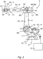
- the Fig. 2 shows an industrial robot 8, which has a robot arm 9 and a robot controller 10.
- the robot arm 9 comprises several links G1 to G7 arranged one after the other and rotatably connected to one another by means of joints L1 to L6.
- the industrial robot 8 has the robot controller 10, which is designed to execute a robot program and the Links G1-G7 and joints L1-L6 of the robot arm 9 to be moved automatically.
- One of the plurality of links G1-G7 forms an end link (G7) of the robot arm 9, which has a tool flange 11.
- the robot controller 10 of the industrial robot 8 is designed or configured to execute a robot program by means of which the joints L1 to L6 of the robot arm 9 can be adjusted or rotated automatically or in manual operation in accordance with the robot program.
- the robot controller 10 is connected to controllable electric drives, the servo motors M1 to M6, which are designed to adjust the respective joints L1 to L6 of the robot arm 9.
- the members G1 to G7 are a robot base frame 13 and a carousel 14 that is mounted so that it can rotate relative to the robot base frame 13 about a vertical axis A1.
- Other members of the robot arm 9 are a swing arm 15, an arm extension 16 and a preferably multi-axis robot hand 17 with a fastening device designed as a tool flange 11 for fastening a tool.
- the swing arm 15 is mounted at the lower end, i.e. at the joint L2 of the swing arm 15, which can also be referred to as the swing arm bearing head, on the carousel 14 so that it can pivot about a preferably horizontal axis of rotation A2.
- the arm extension 16 is pivotally mounted on the first joint L3 of the swing arm 15 about a preferably horizontal axis A3.
- This carries the robot hand 17 at the end with its preferably three rotation axes A4, A5, A6.
- the joints L1 to L6 are each controlled by one of the electric servo motors M1 to M6 via The robot controller 10 can be driven program-controlled.
- the servo motors M1 to M6 are connected to a frequency converter 1 according to the invention, as shown in Fig. 3 and Fig. 4 is shown.
- the frequency converter 1, as in Fig. 3 and Fig. 4 can be connected to an alternating voltage electrical network 2.
- the alternating voltage electrical network 2 can be a three-phase alternating voltage network, for example of 50 Hertz. It can in particular be configured as a TN system.
- the frequency converter 1 If the frequency converter 1 is connected to the AC voltage network 2, its rectifier circuit 3 can convert the AC voltage fed from the electrical AC voltage network 2 into a corresponding DC voltage. The DC voltage is then fed to a DC voltage intermediate circuit 4.
- the DC voltage intermediate circuit 4 is provided with an intermediate circuit capacitor 5 and with a braking resistor 6 that can be connected and disconnected via a braking chopper S7 of the DC voltage intermediate circuit 4.
- At least one inverter circuit 7 fed from the DC voltage intermediate circuit 4 with controllable power semiconductor switches S1 to S6 is connected to the DC voltage intermediate circuit 4.
- inverter circuits 7 are connected to the DC voltage intermediate circuit 4. These several inverter circuits 7 each supply one of several servo motors M1 to M6 according to Fig. 4 .
- Fig. 4 For the sake of illustration, only two inverter circuits 7 and two servo motors M1 and M2 are shown in full.
- the dashed arrows and the designations M3 and M4 indicate a number of further servo motors M3, M4, etc., and further inverter circuits 7, all of which are connected to the common DC voltage intermediate circuit 4.
- a total of six inverter circuits 7 can be provided for the six servo motors M1 to M6 of the six joints L1 to L6 of the robot arm 9.
Landscapes
- Engineering & Computer Science (AREA)
- Power Engineering (AREA)
- Robotics (AREA)
- Mechanical Engineering (AREA)
- Stopping Of Electric Motors (AREA)
- Control Of Multiple Motors (AREA)
Description
- Die Erfindung betrifft ein Verfahren zum abbremsenden Steuern wenigstens eines Servomotors mittels eines Frequenzumrichters, der eine an ein elektrisches Wechselspannungsnetz anschließbare Gleichrichterschaltung, einen im an das elektrische Wechselspannungsnetz angeschlossenen Zustand aus dem elektrischen Wechselspannungsnetz gespeisten Gleichspannungszwischenkreis mit einem Zwischenkreiskondensator und mit einem über einen Brems-Chopper des Gleichspannungszwischenkreises zuschalt- und trennbaren Bremswiderstand, und wenigstens eine aus dem Gleichspannungszwischenkreis gespeiste Wechselrichterschaltung mit ansteuerbaren Leistungshalbleiterschaltern umfasst. Die Erfindung betrifft außerdem einen entsprechend eingerichteten Roboter und ein zugehöriges Computerprogrammprodukt.
- Die
EP 2 224 586 A1 offenbart ein Verfahren zur Steuerung eines motorbetriebenen Industrieroboters, welcher zumindest einen Antriebsmotor umfasst, der von einer an Netzspannung anschließbaren Versorgungsschaltung gespeist wird, welche zumindest eine mit der Netzspannung verbindbare Gleichrichterschaltung, eine Zwischenkreisschaltung mit zumindest einem Zwischenkreiskondensator, sowie eine ausgangsseitig an den Antriebsmotor angeschlossene Brückenschaltereinrichtung umfasst, die eine Wechsel- oder Gleichstromversorgung für den Antriebsmotor bereitstellt, wobei die Versorgungsschaltung des Antriebsmotors durch eine Steuereinrichtung zum Beschleunigen und Abbremsen des Antriebsmotors gesteuert wird. Das dortige Verfahren zum elektrischen Abbremsen des Antriebsmotors umfasst die Schritte des Trennens der Zwischenkreisschaltung vom Netz und des Regelns der Zwischenkreisspannung auf einen vorgegebenen Wert größer Null, wobei der Zwischenkreiskondensator in einem generatorischen Betrieb des Antriebsmotors gespeist wird. - Die
DE 10 2007 059 492 B4 offenbart Industrieroboter, aufweisend einen Roboterarm, der mehrere Achsen und wenigstens einen elektrischen Antrieb mit einem Drehstrommotor und mit einer den Drehstrommotor ansteuernden Leistungselektronik aufweist, wobei die Leistungselektronik einen den Drehstrommotor antreibenden Dreiphasen-Wechselrichter und einen, einen Zwischenkreis-Kondensator aufweisenden und dem Dreiphasen-Wechselrichter vorgeschalteten Zwischenkreis mit einem ersten Bremswiderstand und mit einem ersten Schalter aufweist, wobei der elektrische Antrieb eingerichtet ist, die relevante Achse zu bewegen, wobei der Industrieroboter eingerichtet ist, den Drehstrommotor im Rahmen einer Notbremsung gleichzeitig mittels zweier voneinander unabhängiger elektrischer Strompfade kurz zu schließen und während einer Notbremsung den ersten Schalter zu schließen, um den Bremswiderstand parallel zum Zwischenkreiskondensator zu schalten, so dass einer der beiden elektrischen Strompfade für die Notbremsung durch den ersten Bremswiderstand verläuft. - Die
DE102016208888 zeigt einen Brems-Chopperschalter, der abhängig davon, ob eine Zwischenkreisspannung einen oberen Schwellwert über- oder einen unteren Schwellwert unterschreitet aus- oder eingeschaltet wird. - Die
DE102016203701A1 offenbart einen Roboterarm mit mehreren von Elektromotoren angetriebenen Gelenken und einer Steuereinrichtung. - Aufgabe der Erfindung ist es, ein Verfahren zum abbremsenden Steuern wenigstens eines Servomotors zu schaffen, das besonders effektiv und sicher arbeitet.
- Die Aufgabe wird gelöst durch Verfahren zum abbremsenden Steuern wenigstens eines Servomotors mittels eines Frequenzumrichters, der eine an ein elektrisches Wechselspannungsnetz anschließbare Gleichrichterschaltung, einen im an das elektrische Wechselspannungsnetz angeschlossenen Zustand aus dem elektrischen Wechselspannungsnetz gespeisten Gleichspannungszwischenkreis mit einem Zwischenkreiskondensator und mit einem über einen Brems-Chopper des Gleichspannungszwischenkreises zuschalt- und trennbaren Bremswiderstand, und wenigstens eine aus dem Gleichspannungszwischenkreis gespeiste Wechselrichterschaltung mit ansteuerbaren Leistungshalbleiterschaltern umfasst, aufweisend die Schritte:
- Trennen des Gleichspannungszwischenkreises vom elektrischen Wechselspannungsnetz,
- Bremsen des Servomotors durch Ansteuern der Leistungshalbleiterschalter der Wechselrichterschaltung in einem generatorischen Bremsbetrieb, um die Drehzahl des Servomotors zu reduzieren,
- Ansteuern des Brems-Choppers derart, dass der Bremswiderstand bei einer maximalen Zwischenkreisspannung, die eine Einschaltschwelle für den Brems-Chopper bildet, zugeschaltet wird und bei einer minimalen Zwischenkreisspannung, die eine Ausschaltschwelle für den Brems-Chopper bildet, getrennt wird, wobei
- die Einschaltschwelle und/oder die Ausschaltschwelle während des generatorischen Bremsbetriebs des Servomotors in Abhängigkeit der momentanen Drehzahl des Servomotors dynamisch verändert wird.
- Das erfindungsgemäße Verfahren kann grundsätzlich in Ansteuerung eines einzigen Servomotors durchgeführt werden. Das erfindungsgemäße Verfahren kann jedoch insbesondere in Ansteuerung von wenigstens zwei Servomotoren durchgeführt werden. In der speziellen Ausgestaltung der Ansteuerung von Antrieben eines Roboterarms kann das erfindungsgemäße Verfahren beispielsweise in Ansteuerung von sechs oder sieben Servomotoren, welche die Antriebe eines Roboterarms bilden, durchgeführt werden.
- Unter einem abbremsenden Steuern wird erfindungsgemäß verstanden, dass während der Durchführung des Verfahrens der eine Servomotor oder die mehreren Servomotoren weder durch mechanische Bremsen und weder durch (elektro-)mechanische Bremsen, noch durch eine Kurzschlussbremsung abgebremst werden, sondern während der Durchführung des Verfahrens ausschließlich in einem die Wechselrichterschaltung aktiv angesteuerten generatorischen Betrieb des einen Servomotors oder der mehreren Servomotoren abgebremst werden. In einem solchen aktiv angesteuerten generatorischen Betrieb des einen Servomotors oder der mehreren Servomotoren wird somit über die Wechselrichterschaltung in den Gleichspannungszwischenkreis elektrische Energie eingespeist bzw. Energie ausgetauscht, so dass durch einschaltendes und ausschaltendes Ansteuern der Leistungshalbleiterschalter der Wechselrichterschaltung entsprechende Wechselströme in die Wicklungen des einen Servomotors oder der mehreren Servomotoren eingeleitet werden können, die magnetische Felder erzeugen, welche abbremsende mechanische Kräfte an der Servomotorwelle bzw. an den Servomotorwellen bewirken. Unter einem Abbremsen ist die Reduzierung der Drehzahl der jeweiligen Servomotorwelle zu verstehen. Ein Abbremsen muss nicht notwendiger Weise bis zu einem vollständigen Stillstand der entsprechenden Servomotorwelle durchgeführt werden. Vielmehr kann ein Abbremsen lediglich von einer höheren ersten Drehzahl zu einer niedrigeren zweiten Drehzahl, die geringer ist als die erste Drehzahl, durchgeführt werden.
- Im Falle von zwei oder mehr Servomotoren, die gemäß einem der erfindungsgemäßen Verfahren abbremsend angesteuert werden, müssen nicht sämtliche Servomotoren gleichzeitig abbremsend angesteuert werden. Vielmehr kann zu beliebigen Zeitpunkten wahlweise eine erste Teilgruppe einer Untermenge von Servomotoren abbremsend angesteuert sein und einer zweite Teilgruppe einer anderen Untermenge von Servomotoren, stationär mit einer gleichbleibenden Geschwindigkeit, unangetrieben, d.h. in einem Leerlauf oder sogar beschleunigend angetrieben sein. In einem speziellen Zustand kann lediglich ein einziger Servomotor generatorisch abbremsend angesteuert sein und die sonstigen Servomotoren nicht generatorisch abbremsend angesteuert sein. In einem besonderen Zustand können alle Servomotoren gleichzeitig generatorisch abbremsend angesteuert sein.
- Der wenigstens eine Servomotor wird mittels des erfindungsgemäßen Frequenzumrichters in seiner Position (die Motorposition, d.h. die momentane Winkelstellung der Motorwelle), in seiner Drehzahl, in seiner Beschleunigung und/oder seinem Bremsverhalten (negative Beschleunigung) elektrisch angesteuert. Im Falle von zwei oder mehr Servomotoren weist der Frequenzumrichter eine der Anzahl der Servomotoren entsprechende Anzahl von Wechselrichterschaltungen auf. Die mehreren Wechselrichterschaltungen sind dabei an einen gemeinsamen Gleichspannungszwischenkreis angeschlossen. Der gemeinsame Gleichspannungszwischenkreis wird von einer gemeinsamen Gleichrichterschaltung aus demselben elektrischen Wechselspannungsnetz gespeist, wenn der Frequenzumrichter an das elektrische Wechselspannungsnetz angeschlossen ist. Während des erfindungsgemäßen Verfahrens des abbremsenden Ansteuerns ist der Frequenzumrichter, insbesondere die gemeinsame Gleichrichterschaltung jedoch vom elektrischen Wechselspannungsnetz vorübergehend getrennt. Dies bedeutet, dass im Falle von zwei oder mehreren Servomotoren in einem Zustand in dem keiner der Servomotoren abbremsend angesteuert sind, der Frequenzumrichter wieder an das elektrische Wechselspannungsnetz angeschlossen ist.
- Das elektrische Wechselspannungsnetz stellt elektrische Energie aus einem Stromnetz eines Energieversorgers bereit. Im Allgemeinen wird dies ein Niederspannungsnetz sein. Das Niederspannungsnetz kann insbesondere ein Dreiphasenwechselspannungsnetz sein. Das Dreiphasenwechselspannungsnetz liefert eine sinusförmige Netzwechselspannung. Diese sinusförmige Netzwechselspannung kann insbesondere einen Effektivwert aufweisen, bei dem zwischen einem Außenleiter des Dreiphasenwechselspannungsnetzes und einem Neutralleiter des Dreiphasenwechselspannungsnetzes eine Spannung von beispielsweise 230 Volt und zwischen jeweils zwei der drei Außenleitern eine Spannung von beispielsweise 400 Volt anliegt. Die Netzfrequenz kann beispielsweise 50 Hertz oder 60 Hertz betragen. Das Dreiphasenwechselspannungsnetz kann insbesondere als ein TN-System konfiguriert sein, das drei Außenleiter (L1, L2, L3), einen Neutralleiter (N) und einen Schutzleiter (PE) umfasst.
- Die Gleichrichterschaltung des Frequenzumrichters kann beispielsweise ein Dreiphasengleichrichter sein. Der Dreiphasengleichrichter kann in der Bauart einer ungesteuerten Drehstrombrücke realisiert sein.
- Der Gleichspannungszwischenkreis wird aus dem elektrischen Wechselspannungsnetz mit elektrischer Energie gespeist, wenn der Frequenzumrichter an das elektrische Wechselspannungsnetz angeschlossen ist. Wenn der Gleichspannungszwischenkreis vom elektrischen Wechselspannungsnetz getrennt ist, wie dies in Betriebszeiten der Fall ist, in denen das erfindungsgemäße Verfahren durchgeführt wird, wird der Gleichspannungszwischenkreis ausschließlich durch elektrische Energie aus der Wechselrichterschaltung versorgt, die in einem generatorischen Betrieb des wenigstens einen Servomotors elektrische Energie liefern kann.
- In den Betriebszeiten, in denen das erfindungsgemäße Verfahren durchgeführt wird, kann elektrische Energie außerdem vom Zwischenkreiskondensator abgegeben werden und zwar entweder an die Wechselrichterschaltung oder an den Bremswiderstand.
- Der Bremswiderstand ist ausgebildet, in seinem an den Gleichspannungszwischenkreis zugeschalteten Zustand elektrische Energie aus dem Gleichspannungszwischenkreis zu entnehmen und in Wärme umzuwandeln. In seinem vom Gleichspannungszwischenkreis getrennten Zustand hat der Bremswiderstand auf den Gleichspannungszwischenkreis keine elektrische Wirkung, d.h. der Gleichspannungszwischenkreis bleibt im getrennten Zustand des Bremswiderstands vom Bremswiderstand unbeeinflusst.
- Der Brems-Chopper, über den der Bremswiderstand dem Gleichspannungszwischenkreis zugeschaltet und/oder getrennt wird, ist ein ansteuerbarer Schalter. Der Brems-Chopper kann insoweit pulsweitengesteuert betrieben sein.
- Die aus dem Gleichspannungszwischenkreis gespeiste Wechselrichterschaltung umfasst Leistungshalbleiterschalter, die elektronisch, beispielsweise von zugeordneten Treiberschaltungen angesteuert sein können. Die Wechselrichterschaltung kann ein Dreiphasen-Wechselrichter sein und beispielsweise als ein Zweistufen-Wechselrichter (U-Umrichter) oder ein Pulswechselrichter ausgebildet sein. In der Wechselrichterschaltung führen die Leistungshalbleiterschalter die elektrische Energie an den Servomotor, wenn Strom und Spannung das gleiche Vorzeichen haben. Die elektrische Energie fließt somit vom Gleichspannungszwischenkreis ab und in den Servomotor hinein. Im generatorischen Betrieb führen erfindungsgemäß nicht die den Leistungshalbleiterschaltern zugeordneten Freilaufdioden die elektrische Energie ab, um generatorische Energie aus dem Servomotor bzw. den Servomotoren in den Gleichspannungszwischenkreis d.h. in den Zwischenkreiskondensator zurückzuliefern, sondern die Leistungshalbleiterschalter bleiben aktiv und werden entsprechend von den Leistungshalbleiterschaltern zugeordneten Treiberschaltungen angesteuert, um elektrische Energie von den Servomotoren abzuziehen und in den Gleichspannungszwischenkreis d.h. in den Zwischenkreiskondensator einzuspeisen.
- Bei dem erfindungsgemäßen Verfahren erfolgt zunächst ein Trennen des Gleichspannungszwischenkreises vom elektrischen Wechselspannungsnetz. Dies ist beispielsweise im Falle einer Notabschaltung der jeweiligen Maschine, die von dem wenigstens einen Servomotor angetrieben wird, zumindest zweckmäßig oder sogar im Hinblick auf bestimmte zu beachtende Sicherheitsanforderungen zwingend erforderlich.
- So ist beispielsweise bei Industrierobotern im Falle eines Not-Halts der Kategorie 0 (z.B. gemäß Norm EN 60204) eine sofortige Unterbrechung der elektrischen Energieversorgung vorgeschrieben, insbesondere wenn beispielsweise eine mechanische Trennung d.h. ein Auskuppeln im Antriebstrang und/oder ein mechanisches Bremsen alleine nicht möglich ist.
- Andererseits kann eine Maschine, wie der beispielhafte Industrieroboter Systemzustände aufweisen, in denen eine gesteuerte Drehzahlreduzierung der Servomotoren, insbesondere bis auf einen Stillstand bei der Drehzahl Null, schneller erfolgt, als durch eine bloße mechanische Bremsung, bei der die Servomotoren nicht geregelt in ihren Drehzahlen heruntergefahren werden.
- Bei dem erfindungsgemäßen Verfahren erfolgt deshalb ein Bremsen des wenigstens einen Servomotors durch aktives Ansteuern der Leistungshalbleiterschalter der Wechselrichterschaltung in einem generatorischen Bremsbetrieb, um die Drehzahl des Servomotors steuerungstechnisch kontrolliert zu reduzieren. Da der Frequenzumrichter in der betroffenen Situation jedoch vom elektrischen Wechselspannungsnetz getrennt ist, wird erfindungsgemäß sichergestellt, dass im Gleichspannungszwischenkreis einerseits genug elektrische Energie vorhanden bleibt, die ausreicht, um die Wechselrichterschaltung zu betreiben, jedoch andrerseits die Energiemenge im Gleichspannungszwischenkreis auf ein mögliches Minimum reduziert wird, so dass ein ungewollter ggf. fehlerbehafteter Wiederanlauf des wenigstens einen Servomotors zumindest weitgehend oder sogar vollständig unterbunden werden kann. So kann auch die Funktion eines sicher abgeschalteten Moments (STO, Safe Torque Off) realisiert werden.
- Erfindungsgemäß wird dies erreicht, indem der Brems-Chopper derart angesteuert wird, dass der Bremswiderstand bei einer maximalen Zwischenkreisspannung, die eine Einschaltschwelle für den Brems-Chopper bildet, zugeschaltet wird und bei einer minimalen Zwischenkreisspannung, die eine Ausschaltschwelle für den Brems-Chopper bildet, getrennt wird. Gleichzeitig werden die Einschaltschwelle und/oder die Ausschaltschwelle während des generatorischen Bremsbetriebs des Servomotors in Abhängigkeit der momentanen Drehzahl des Servomotors dynamisch verändert. Durch eine dynamische Änderung von Einschaltschwelle und/oder Ausschaltschwelle kann die im Gleichspannungszwischenkreis zu speichernde Menge an elektrischer Energie dynamisch an die momentan erforderlichen Bedingungen angepasst werden und zwar hinsichtlich beider Zielgrößen, nämlich hinsichtlich einer ausreichend hohen Energiemenge, um die Wechselrichterschaltung mit elektrischer Energie versorgen zu können, so dass der Servomotor generatorisch betrieben d.h. abgebremst werden kann, und hinsichtlich einer möglichst niedrigen Energiemenge, um genügend Energie aus dem System zu nehmen, so dass ein möglicherweise gefährlicher, unbeabsichtigter Wiederanlauf des Servomotors zuverlässig verhindert ist.
- Im Gegensatz zum Stand der Technik, nach dem es bekannt ist, die am Zwischenkreiskondensator anliegende Zwischenkreisspannung lediglich auf einen vorgegebenen Soll-Wert zu regeln, wird erfindungsgemäß ein solcher Soll-Wert nicht fest vorgegeben, sondern die Einschaltschwelle und/oder die Ausschaltschwelle des Brems-Choppers dynamisch während des generatorischen Betriebs des wenigstens einen Servomotors verändert.
- In einer speziellen Ausführungsform werden die Einschaltschwelle und/oder die Ausschaltschwelle während des generatorischen Bremsbetriebs des Servomotors in Abhängigkeit der momentanen Drehzahl des Servomotors dynamisch derart verändert, dass die Zwischenkreisspannung mit abnehmender Drehzahl des Servomotors kontinuierlich reduziert wird.
- Im Falle von mehr als einem einzigen Servomotor kann die Zwischenkreisspannung mit abnehmender Drehzahl desjenigen Servomotors kontinuierlich reduziert wird, der momentan in seinem generatorischen Betrieb die höchste Spannung induziert. Im Laufe der Durchführung eines erfindungsgemäßen Verfahrens d.h. während der Dauer eines Bremsvorgangs kann gegebenenfalls der in Bezug genommene Servomotor in dessen Abhängigkeit die Zwischenkreisspannung mit dessen abnehmender Drehzahl kontinuierlich reduziert wird, wechseln. Wenn also derjenige Servomotor, in dessen Abhängigkeit die Zwischenkreisspannung bisher reduziert wird, zum Stehen gekommen ist oder seine momentane Drehzahl zumindest soweit reduziert ist, dass ein anderer Servomotor eine höhere Drehzahl aufweist, also folglich eine dann größere Spannung im Zwischenkreisspannung induziert, kann zur Regelung der Zwischenkreisspannung sozusagen auf diesen anderen Servomotor umgeschaltet werden, so dass dieser andere Servomotor insoweit die neue Leitgröße für die Regelung der Zwischenkreisspannung bildet.
- Die Drehzahl des Servomotors kann auf Grundlage einer mittels eines Motorpositionssensors gemessenen momentanen Drehzahl des Servomotors bestimmt werden. Dazu kann die momentane Drehzahl des Servomotors aus zwei erfassten Winkelstellungen der Servomotorwelle zu zwei verschiedenen Zeitpunkten bestimmt d.h. berechnet werden.
- Alternativ zu einer Messung der Drehzahl des Servomotors mittels eines Motorpositionssensors oder ergänzend zu einer Messung der Drehzahl des Servomotors mittels eines Motorpositionssensors, beispielsweise zur Schaffung einer redundanten, insbesondere diversitären Auswertung, kann die Drehzahl des Servomotors auf Grundlage der gemessenen, momentan im Servomotor vorherrschenden Motorspannung des Servomotors bestimmt werden. Dazu kann auf Basis einer bauartbedingten festen Kennlinie des Servomotors über die momentan vorliegende, gemessene Motorspannung aus der Kennlinie die momentane Drehzahl des Servomotor abgelesen werden.
- Die Reduktion der Zwischenkreisspannung kann insbesondere proportional zur Abnahme der Drehzahl des Servomotors durchgeführt werden. Die Reduktion der Zwischenkreisspannung kann insbesondere synchron zur Abnahme der Drehzahl des Servomotors durchgeführt werden.
- Mit abnehmender Drehzahl des Servomotors reduziert sich die kinetische Energie des an den Servomotor angekoppelten kinematischen Systems, wie beispielsweise eines an die Motorwelle des Servomotors angeschlossenen Getriebes, Gliedes des Roboterarms und/oder einer distalen Teilkette von Gliedern und Gelenken des Roboterarms. In Folge dessen wird zum Abbremsen des angekoppelten kinematischen Systems aufgrund der reduzierten kinetischen Energie nur noch eine geringere Bremsenergie benötigt, um das sich noch verlangsamt in Bewegung befindliche kinematischen System bis zum Stillstand abbremsen zu können. Im Idealfall ist also in demjenigen Moment, in dem das an den Servomotor angekoppelte kinematische System zum Stilltand kommt, die elektrische Energie im Zwischenkreis vollständig oder zumindest sehr weitgehend entnommen. Daraus ergibt sich dann ein weiterer Vorteil, nämlich, dass ein ungewolltes d.h. gegebenenfalls fehlerverursachtes Wiederanlaufen des Servomotors schon deshalb nicht mehr möglich ist, weil nicht genug elektrische Energie im Zwischenkreis vorhanden ist, um den Servomotor anlaufen lassen zu können.
- In einer besonderen Weiterbildung können die Einschaltschwelle und/oder die Ausschaltschwelle während des generatorischen Bremsbetriebs des Servomotors in Abhängigkeit der momentanen Drehzahl des Servomotors derart verändert werden, dass die Veränderung der Einschaltschwelle und/oder der Ausschaltschwelle auf Grundlage einer mittels eines Motorpositionssensors gemessenen momentanen Drehzahl des Servomotors oder auf Grundlage des gemessenen momentan im Servomotor vorherrschenden Motorspannung des Servomotors durchgeführt wird.
- In einer ersten Ausführungsvariante kann also die Veränderung der Einschaltschwelle und/oder der Ausschaltschwelle auf Grundlage einer mittels eines Motorpositionssensors gemessenen momentanen Drehzahl des Servomotors durchgeführt werden. Der Motorpositionssensor dient der Erfassung der momentanen Drehwinkellage der Motorwelle des Servomotors. Der Motorpositionssensor wird u.a. auch als Drehgeber bezeichnet. Aus jeweils zwei zu verschiedenen Zeitpunkten erfassten Drehwinkellagen der Motorwelle des Servomotors kann auch die Drehgeschwindigkeit und/oder die Drehbeschleunigung der Motorwelle des Servomotors abgeleitet und insofern bestimmt werden. Als ein Motorpositionssensor kann beispielsweise ein Resolver, ein Inkrementalgeber, aber auch ein Absolutwertgeber herangezogen werden.
- In einer zweiten Ausführungsvariante kann jedoch die Veränderung der Einschaltschwelle und/oder der Ausschaltschwelle auch auf Grundlage der gemessenen momentan im Servomotor vorherrschenden Motorspannung des Servomotors durchgeführt werden. In Servomotoren ist bekanntlich die Motorspannung, d.h. die elektrische Spannung in den Wicklungen proportional zur Drehzahl der Motorwelle des Servomotors. Die Motorspannung des Servomotors kann insoweit direkt aus dem Schaltkreis, an den die Wechselrichterschaltung des erfindungsgemäßen Frequenzumrichters angeschlossen ist, elektrisch abgegriffen werden. Folglich sind in dieser zweiten Ausführungsvariante keine separaten Sensorbauteile notwendig.
- Die Einschaltschwelle und/oder die Ausschaltschwelle können während des generatorischen Bremsbetriebs des Servomotors in Abhängigkeit der momentanen Drehzahl des Servomotors bis zu einem vorgegebenen Minimalschwellwert abgesenkt werden, insbesondere der Ausschaltschwellwert auf einen Minimalschwellwert abgesenkt werden, der unter der Netzspannung des Wechselspannungsnetzes liegt.
- Ganz allgemein definieren die Einschaltschwelle und die Ausschaltschwelle einen Zweipunktregler mit Hysterese, derart, dass bei Überschreiten der Einschaltschwelle von einer niedrigeren Spannung kommend der Brems-Chopper den Bremswiderstand in den Gleichspannungszwischenkreis zuschaltet, so dass in dem Bremswiderstand elektrische Energie in Wärme umgewandelt wird und die Zwischenkreisspannung sinkt. Wenn die Spannung von der höheren Spannung kommend sinkt, muss die Spannung im Gleichspannungszwischenkreis dann jedoch über die Einschaltschwelle hinaus weiter sinken, bis sie unter die Spannung der Ausschaltschwelle sinkt. Die Ausschaltschwelle liegt insoweit stets unter der Einschaltschwelle und zwar um eine Spannungsdifferenz, welche die Hysterese bestimmt. Bei Unterschreiten der Ausschaltschwelle von einer höheren Spannung kommend trennt der Brems-Chopper den Bremswiderstand wieder von dem Gleichspannungszwischenkreis, so dass in dem Gleichspannungszwischenkreis die Zwischenkreisspannung wieder ansteigen kann.
- Indem der Minimalschwellwert auf einen Spannungswert abgesenkt wird, der unter der Netzspannung des Wechselspannungsnetzes liegt, kann die Zwischenkreisspannung maximal abgesenkt werden, was eine Maximierung der generatorischen Leistung zulässt, so dass der Servomotor bzw. die Servomotoren mit maximaler generatorischer Energie abgebremst werden können.
- Der Minimalschwellwert könnte somit bis auf Null abgesenkt werden. Allerdings kann es je nach Ansteuerungsart vorgesehen sein, dass die Treiber der Wechselrichterschaltung d.h. die Leistungshalbleiterschalter der Wechselrichterschaltung auch mittels elektrischer Energie aus dem Gleichspannungszwischenkreis des Frequenzumrichters gespeist werden. In diesem Falle ist eine Absenkung des Minimalschwellwertes bis auf null Volt nicht zweckmäßig.
- In einer besonderen Ausführungsform können deshalb die Einschaltschwelle und/oder die Ausschaltschwelle während des generatorischen Bremsbetriebs des Servomotors in Abhängigkeit der momentanen Drehzahl des Servomotors lediglich bis zu einem solchen Minimalschwellwert abgesenkt werden, bei dem im Gleichspannungszwischenkreis eine Mindestspannung anliegt, bei welcher der generatorische Bremsbetrieb des Servomotors durch Ansteuern der Leistungshalbleiterschalter der Wechselrichterschaltung weiterhin sichergestellt ist. Dieser Minimalschwellwert kann beispielsweise zwischen Null und der Netzspannung des Wechselspannungsnetzes liegen.
- Zur gleichzeitigen Ansteuerung von mindestens zwei Servomotoren kann der Frequenzumrichter eine der Anzahl der Servomotoren entsprechende Anzahl von Wechselrichterschaltungen aufweisen, die an den gemeinsamen Gleichspannungszwischenkreis des Frequenzumrichters angeschlossen sind, wobei die Einschaltschwelle und/oder die Ausschaltschwelle während des generatorischen Bremsbetriebs eines oder mehrerer der mindestens zwei Servomotoren in Abhängigkeit der momentanen Drehzahl desjenigen Servomotors dynamisch verändert wird, der momentan die höchste Zwischenkreisspannung induziert.
- Im Anwendungsfall eines beispielhaften Roboterarms kann der Roboterarm mehrere Gelenke und mehrere Glieder aufweisen, die durch die Bewegungen der Gelenke des Roboterarms gegeneinander verstellbar sind. Dabei kann jedem Gelenk ein eigener Servomotor zugeordnet sein. Jeder dieser mehreren Servomotoren ist ausgebildet, das jeweils ihm zugeordnete Gelenk des Roboterarms zu verstellen und zwar durch automatisches Ansteuern des Servomotors. Der Roboterarm kann dazu eine Steuervorrichtung aufweisen, die ausgebildet ist zum automatischen Ansteuern der Servomotoren des Roboterarms, um die Glieder des Roboterarms durch angetriebenes Bewegen der Gelenke automatisch gegeneinander zu verstellen.
- Jedes Gelenk und damit jeder diesem jeweiligen Gelenk zugeordnete Servomotor bewegt ein kinematisches System, das jeweils durch das diesem Servomotor in der kinematischen Kette des Roboterarms vorgelagerte, distale kinematische Teilsystem gebildet wird. So müssen die in der kinematischen Kette eher proximal angeordneten Servomotoren (Servomotoren der Grundachsen des Roboterarms) im Allgemeinen eine höhere kinetische Energie abbremsen, als die eher distal angeordneten Servomotoren (Servomotoren der Handachsen des Roboterarms). Je nach Pose der Gelenke des Roboterarms kann jedoch zu jedem beliebigen Zeitpunkt ein anderer Servomotor mit der momentan höchsten Bremslast belastet sein. So kann beispielsweise eine Situation auftreten, wo ein sich gerade entgegen der Schwerkraft nach oben bewegendes Grundgelenk abgebremst werden soll und somit die Bremskraft weitgehend durch die Schwerkraft bereitgestellt wird und der zugeordnete Servomotor somit keiner besonderen elektrischen Bremslast ausgesetzt ist. Andererseits kann ein eher leichtes Handgelenk des Roboterarms sich gerade in Schwerkraftrichtung bewegen, so dass beim Abbremsen der einwirkenden Erdbeschleunigung zusätzlich durch den Servomotor entgegengewirkt werden muss und somit dieser dem leichteren Handgelenk zugeordnete Servomotor einer besonders hohen elektrischen Bremslast ausgesetzt ist.
- Im Laufe der Durchführung eines erfindungsgemäßen Verfahrens d.h. während der Dauer eines Bremsvorgangs kann deshalb gegebenenfalls der in Bezug genommene Servomotor in dessen Abhängigkeit die Zwischenkreisspannung mit dessen abnehmender Drehzahl kontinuierlich reduziert wird, wechseln. Wenn also derjenige Servomotor, in dessen Abhängigkeit die Zwischenkreisspannung bisher reduziert wird, zum Stehen gekommen ist oder seine momentane Drehzahl zumindest soweit reduziert ist, dass ein anderer Servomotor eine höhere Drehzahl aufweist, also folglich eine dann größere Spannung im Zwischenkreisspannung induziert, kann zur Regelung der Zwischenkreisspannung sozusagen auf diesen anderen Servomotor umgeschaltet werden, so dass dieser andere Servomotor insoweit die neue Leitgröße für die Regelung der Zwischenkreisspannung bildet.
- In allen erfindungsgemäßen Ausführungsvarianten kann die elektrische Energie im Gleichspannungszwischenkreis während der dynamischen Veränderung der Einschaltschwelle und/oder der Ausschaltschwelle während des generatorischen Bremsbetriebs des Servomotors in denjenigen Zuständen des Gleichspannungszwischenkreises, in denen der Brems-Chopper den Bremswiderstand getrennt hat, erhöht werden, indem der Zwischenkreiskondensator ausschließlich durch die von dem wenigstens einen Servomotor generierte Energie aus der Wechselrichterschaltung gespeist wird.
- Der wenigstens eine Servomotor kann speziell eine permanentmagnet-erregte Synchronmaschine sein.
- Die erfindungsgemäße Aufgabe wird außerdem gelöst durch einen Roboter, aufweisend einen Roboterarm mit mehreren Gelenken und mehreren Gliedern, die durch die Bewegungen der Gelenke des Roboterarms gegeneinander verstellbar sind, wobei wenigstens einem der Gelenke ein Servomotor zugeordnet ist, welcher ausgebildet ist, das wenigstens eine Gelenk zu verstellen und zwar durch automatisches Ansteuern des Servomotors, und aufweisend eine Steuervorrichtung, die ausgebildet ist zum automatischen Ansteuern wenigstens eines Servomotors des Roboterarms, um die Glieder des Roboterarms durch angetriebenes Bewegen der Gelenke automatisch gegeneinander zu verstellen, wobei die Steuervorrichtung ausbildet und einrichtet ist, ein Verfahren nach einem beschriebenen Ausführungsformen durchzuführen.
- Die Steuervorrichtung kann als ein Teil einer Robotersteuerung ausgebildet sein. Alternativ kann die Steuervorrichtung jedoch auch als separate Steuereinheit ausgebildet sein, die mit der Robotersteuerung zusammenwirkt, beispielsweise mittels einer Kommunikationsverbindung. Die Steuervorrichtung ist insbesondere ausgebildet einen Frequenzumrichter anzusteuern, der eine an ein elektrisches Wechselspannungsnetz anschließbare Gleichrichterschaltung, einen im an das elektrische Wechselspannungsnetz angeschlossenen Zustand aus dem elektrischen Wechselspannungsnetz gespeisten Gleichspannungszwischenkreis mit einem Zwischenkreiskondensator und mit einem über einen Brems-Chopper des Gleichspannungszwischenkreises zuschalt- und trennbaren Bremswiderstand, und wenigstens eine aus dem Gleichspannungszwischenkreis gespeiste Wechselrichterschaltung mit ansteuerbaren Leistungshalbleiterschaltern umfasst.
- Die erfindungsgemäße Aufgabe wird außerdem gelöst durch ein Computerprogrammprodukt aufweisend einen maschinenlesbaren Träger, auf dem Programmcode gespeichert ist, der von einer Steuervorrichtung des erfindungsgemäßen Roboters auslesbar ist und der ausgelesen die Steuervorrichtung ausbildet und/oder einrichtet, ein Verfahren nach einem der beschriebenen Ausführungsformen durchzuführen, wenn der Programmcode von der Steuervorrichtung ausgeführt wird.
- Das Computerprogrammprodukt kann beispielsweise eine CD, eine DVD oder ein USB-Stick sein. Das Computerprogrammprodukt kann aber auch eine Steuerungskarte sein, auf der Mikroprozessoren eingebunden sind. Das Computerprogrammprodukt kann jedoch auch in Form eines Downloads realisiert sein, der über das Internet oder ein anderes Netzwerk angeboten und verkauft werden kann.
- Der maschinenlesbare Träger kann somit eine CD, eine DVD oder ein Mikroprozessor sein, auf dem der Programmcode gespeichert ist. Der maschinenlesbare Träger kann aber auch eine Festplatte oder ein SSD-Laufwerk sein, auf das der Programmcode heruntergeladen wurde, beispielsweise mittels eines Downloads, insbesondere in Form von Datenpaketen.
- Der Programmcode kann durch ein editiertes Programm und/oder Daten repräsentiert sein, die auf dem maschinenlesbaren Träger gespeichert sind.
- Durch ein Auslesen des editiertes Programm und/oder der Daten wird die auslesende Steuervorrichtung ausbildet und/oder einrichtet, das erfindungsgemäße Verfahren ausführen zu können.
- Das erfindungsgemäße Verfahren wird durchgeführt, wenn die Steuervorrichtung den Programmcode d.h. das editierte Programm tatsächlich entsprechend ausführt und/oder die Daten tatsächlich entsprechend verarbeitet.
- Konkrete Ausführungsbeispiele der Erfindung sind in der nachfolgenden Beschreibung unter Bezugnahme auf die beigefügten Figuren näher erläutert. Konkrete Merkmale dieser exemplarischen Ausführungsbeispiele können unabhängig davon, in welchem konkreten Zusammenhang sie erwähnt sind, gegebenenfalls auch einzeln oder in weiteren Kombinationen betrachtet, allgemeine Merkmale der Erfindung darstellen.
- Es zeigen:
- Fig. 1
- ein Ablaufschema des erfindungsgemäßen Verfahrens,
- Fig. 2
- eine Seitenansicht eines beispielhaften Industrieroboters, der einen Roboterarm mit Gliedern, Gelenken und Servomotoren umfasst, und der eine Robotersteuerung aufweist, die ausgebildet ist, ein erfindungsgemäßes Verfahren durchzuführen,
- Fig. 3
- eine schematische Darstellung eines Schaltbildes eines beispielhaften Frequenzumrichters mit einem Servomotor, und
- Fig. 4
- eine schematische Darstellung eines Schaltbildes eines beispielhaften abgewandelten Frequenzumrichters mit zwei oder mehre Servomotoren, die an einem gemeinsamen Gleichspannungszwischenkreis angeschlossen sind.
- In
Fig. 1 ist schematisch der Ablauf des grundlegenden erfindungsgemäßen Verfahrens zum abbremsenden Steuern wenigstens eines Servomotors M mittels eines Frequenzumrichters 1 (Fig. 3 ,Fig. 4 ) dargestellt. - Der Frequenzumrichter 1 kann, wie in
Fig. 3 undFig. 4 aufgezeigt ist, eine an ein elektrisches Wechselspannungsnetz 2 anschließbare Gleichrichterschaltung 3, einen im an das elektrische Wechselspannungsnetz 2 angeschlossenen Zustand aus dem elektrischen Wechselspannungsnetz 2 gespeisten Gleichspannungszwischenkreis 4 mit einem Zwischenkreiskondensator 5 und mit einem über einen Brems-Chopper S7 des Gleichspannungszwischenkreises 4 zuschalt- und trennbaren Bremswiderstand 6, und wenigstens eine aus dem Gleichspannungszwischenkreis 4 gespeiste Wechselrichterschaltung 7 mit ansteuerbaren Leistungshalbleiterschaltern S1 bis S6 aufweisen. - Das erfindungsgemäße Verfahren, wie in
Fig.1 dargestellt, weist die folgenden Schritte auf:
Im ersten Schritt V1 erfolgt ein Trennen des Gleichspannungszwischenkreises 4 vom elektrischen Wechselspannungsnetz 2. - In einem folgenden zweiten Schritt V2 erfolgt ein Bremsen des Servomotors M durch Ansteuern der Leistungshalbleiterschalter S1-S6 der Wechselrichterschaltung 7 in einem generatorischen Bremsbetrieb, um die Drehzahl des Servomotors M zu reduzieren,
- In einem dritten Schritt V3 erfolgt ein Ansteuern des Brems-Choppers S7 derart, dass der Bremswiderstand 6 bei einer maximalen Zwischenkreisspannung, die eine Einschaltschwelle für den Brems-Chopper S7 bildet, zugeschaltet wird und bei einer minimalen Zwischenkreisspannung, die eine Ausschaltschwelle für den Brems-Chopper S7 bildet, getrennt wird, wobei gemäß Schritt V4 die Einschaltschwelle und/oder die Ausschaltschwelle während des generatorischen Bremsbetriebs des Servomotors M in Abhängigkeit der momentanen Drehzahl des Servomotors M dynamisch verändert wird.
- Die
Fig. 2 zeigt einen Industrieroboter 8, der einen Roboterarm 9 und eine Robotersteuerung 10 aufweist. Der Roboterarm 9 umfasst im Falle des vorliegenden Ausführungsbeispiels mehrere, nacheinander angeordnete, und mittels Gelenke L1 bis L6 drehbar miteinander verbundene Glieder G1 bis G7. - Der Industrieroboter 8 weist die Robotersteuerung 10 auf, die ausgebildet ist, ein Roboterprogramm auszuführen und die Glieder G1-G7 und Gelenke L1-L6 des Roboterarms 9 automatisch zu bewegen. Eines der mehreren Glieder G1-G7 bildet ein Endglied (G7) des Roboterarms 9, das einen Werkzeugflansch 11 aufweist.
- Die Robotersteuerung 10 des Industrieroboters 8 ist ausgebildet bzw. eingerichtet, ein Roboterprogramm auszuführen, durch welches die Gelenke L1 bis L6 des Roboterarms 9 gemäß des Roboterprogramms automatisiert oder in einem Handfahrbetrieb automatisch verstellt bzw. drehbewegt werden können. Dazu ist die Robotersteuerung 10 mit ansteuerbaren elektrischen Antrieben, den Servomotoren M1 bis M6 verbunden, die ausgebildet sind, die jeweiligen Gelenke L1 bis L6 des Roboterarms 9 zu verstellen.
- Bei den Gliedern G1 bis G7 handelt es sich im Falle des vorliegenden Ausführungsbeispiels um ein Robotergrundgestell 13 und ein relativ zum Robotergrundgestell 13 um eine vertikal verlaufende Achse A1 drehbar gelagertes Karussell 14. Weitere Glieder des Roboterarms 9 sind eine Schwinge 15, ein Armausleger 16 und eine vorzugsweise mehrachsige Roboterhand 17 mit einer als Werkzeugflansch 11 ausgeführten Befestigungsvorrichtung zum Befestigen eines Werkzeugs. Die Schwinge 15 ist am unteren Ende, d.h. an dem Gelenk L2 der Schwinge 15, das auch als Schwingenlagerkopf bezeichnet werden kann, auf dem Karussell 14 um eine vorzugsweise horizontale Drehachse A2 schwenkbar gelagert.
- Am oberen Ende der Schwinge 15 ist an dem ersten Gelenk L3 der Schwinge 15 wiederum um eine ebenfalls vorzugsweise horizontale Achse A3 der Armausleger 16 schwenkbar gelagert. Dieser trägt endseitig die Roboterhand 17 mit ihren vorzugsweise drei Drehachsen A4, A5, A6. Die Gelenke L1 bis L6 sind durch jeweils einen der elektrischen Servomotoren M1 bis M6 über die Robotersteuerung 10 programmgesteuert antreibbar. Den Servomotoren M1 bis M6 ist dazu ein erfindungsgemäßer Frequenzumrichter 1, wie in
Fig. 3 undFig. 4 aufgezeigt ist, zugeordnet. - Der Frequenzumrichter 1, wie in
Fig. 3 undFig. 4 aufgezeigt ist, kann an ein elektrisches Wechselspannungsnetz 2 anschließbar sein. Das elektrische Wechselspannungsnetz 2 kann ein Dreiphasenwechselspannungsnetz, beispielsweise von 50 Hertz, sein. Es kann insbesondere als ein TN-System konfiguriert sei. - Ist der Frequenzumrichter 1 an das Wechselspannungsnetz 2 angeschlossen, so kann dessen Gleichrichterschaltung 3 die aus dem elektrischen Wechselspannungsnetz 2 gespeiste Wechselspannung in eine entsprechende Gleichspannung umwandeln. Die Gleichspannung wird dann einem Gleichspannungszwischenkreis 4 zugeführt. Der Gleichspannungszwischenkreis 4 ist mit einem Zwischenkreiskondensator 5 und mit einem über einen Brems-Chopper S7 des Gleichspannungszwischenkreises 4 zuschalt- und trennbaren Bremswiderstand 6 versehen.
- An den Gleichspannungszwischenkreis 4 schließt sich wenigstens eine aus dem Gleichspannungszwischenkreis 4 gespeiste Wechselrichterschaltung 7 mit ansteuerbaren Leistungshalbleiterschaltern S1 bis S6 an.
- Im Falle des Ausführungsbeispiels der
Fig. 3 ist lediglich eine einzige Wechselrichterschaltung 7 an den Gleichspannungszwischenkreis 4 angeschlossen. Diese einzige Wechselrichterschaltung 7 versorgt den einzigen Servomotor M gemäßFig. 3 . - Im Falle des Ausführungsbeispiels der
Fig. 4 sind mehrere Wechselrichterschaltungen 7 an den Gleichspannungszwischenkreis 4 angeschlossen. Diese mehreren Wechselrichterschaltungen 7 versorgen jeweils einen von mehreren Servomotoren M1 bis M6 gemäßFig. 4 . InFig. 4 sind zur Veranschaulichung lediglich zwei Wechselrichterschaltungen 7 und zwei Servomotoren M1 und M2 vollständig dargestellt. Die gestrichelten Pfeile und die Bezeichnungen M3 und M4 deuten eine Anzahl von weiteren Servomotoren M3, M4, usw., und weiteren Wechselrichterschaltungen 7 an, die alle an den gemeinsamen Gleichspannungszwischenkreis 4 angeschlossen sind. - Im Falle des in
Fig. 2 gezeigten beispielhaften Industrieroboters 8 können beispielsweise insgesamt sechs Wechselrichterschaltungen 7 für die sechs Servomotoren M1 bis M6 der sechs Gelenke L1 bis L6 des Roboterarms 9 vorgesehen sein.
Claims (10)
- Verfahren zum abbremsenden Steuern wenigstens eines Servomotors (M, M1-M6) mittels eines Frequenzumrichters (1), der eine an ein elektrisches Wechselspannungsnetz (2) anschließbare Gleichrichterschaltung (3), einen im an das elektrische Wechselspannungsnetz (2) angeschlossenen Zustand aus dem elektrischen Wechselspannungsnetz (2) gespeisten Gleichspannungszwischenkreis (4) mit einem Zwischenkreiskondensator (5) und mit einem über einen Brems-Chopper (S7) des Gleichspannungszwischenkreises (4) zuschalt- und trennbaren Bremswiderstand (6), und wenigstens eine aus dem Gleichspannungszwischenkreis (4) gespeiste Wechselrichterschaltung (7) mit ansteuerbaren Leistungshalbleiterschaltern (S1-S6) umfasst, aufweisend die Schritte:- Trennen des Gleichspannungszwischenkreises (4) vom elektrischen Wechselspannungsnetz (2),- Bremsen des Servomotors (M, M1-M6) durch Ansteuern der Leistungshalbleiterschalter (S1-S6) der Wechselrichterschaltung (7) in einem generatorischen Bremsbetrieb, um die Drehzahl des Servomotors (M, M1-M6) zu reduzieren,
gekennzeichnet durch- Ansteuern des Brems-Choppers (S7) derart, dass der Bremswiderstand (6) bei einer maximalen Zwischenkreisspannung, die eine Einschaltschwelle für den Brems-Chopper (S7) bildet, zugeschaltet wird und bei einer minimalen Zwischenkreisspannung, die eine Ausschaltschwelle für den Brems-Chopper (S7) bildet, getrennt wird, wobei- die Einschaltschwelle und/oder die Ausschaltschwelle während des generatorischen Bremsbetriebs des Servomotors (M, M1-M6) in Abhängigkeit der momentanen Drehzahl des Servomotors (M, M1-M6) dynamisch verändert wird. - Verfahren nach Anspruch 1, dadurch gekennzeichnet, dass die Einschaltschwelle und/oder die Ausschaltschwelle während des generatorischen Bremsbetriebs des Servomotors (M, M1-M6) in Abhängigkeit der momentanen Drehzahl des Servomotors (M, M1-M6) dynamisch derart verändert werden, dass die Zwischenkreisspannung mit abnehmender Drehzahl des Servomotors (M, M1-M6) kontinuierlich reduziert wird.
- Verfahren nach Anspruch 2, dadurch gekennzeichnet, dass die Reduktion der Zwischenkreisspannung proportional zur Abnahme der Drehzahl des Servomotors (M, M1-M6) durchgeführt wird.
- Verfahren nach einem der Ansprüche 1 bis 3, dadurch gekennzeichnet, dass die Einschaltschwelle und/oder die Ausschaltschwelle während des generatorischen Bremsbetriebs des Servomotors (M, M1-M6) in Abhängigkeit der momentanen Drehzahl des Servomotors (M, M1-M6) verändert wird, indem die Veränderung der Einschaltschwelle und/oder der Ausschaltschwelle auf Grundlage einer mittels eines Motorpositionssensors gemessenen momentanen Drehzahl des Servomotors (M, M1-M6) oder auf Grundlage der gemessenen momentan im Servomotor (M, M1-M6) vorherrschenden Motorspannung des Servomotors (M, M1-M6) durchgeführt wird.
- Verfahren nach einem der Ansprüche 1 bis 4, dadurch gekennzeichnet, dass die Einschaltschwelle und/oder die Ausschaltschwelle während des generatorischen Bremsbetriebs des Servomotors (M, M1-M6) in Abhängigkeit der momentanen Drehzahl des Servomotors (M, M1-M6) bis zu einem vorgegebenen Minimalschwellwert abgesenkt wird, insbesondere der Ausschaltschwellwert auf einen Minimalschwellwert abgesenkt wird, der unter der Netzspannung des Wechselspannungsnetzes (2) liegt.
- Verfahren nach einem der Ansprüche 1 bis 5, dadurch gekennzeichnet, dass die Einschaltschwelle und/oder die Ausschaltschwelle während des generatorischen Bremsbetriebs des Servomotors (M, M1-M6) in Abhängigkeit der momentanen Drehzahl des Servomotors (M, M1-M6) lediglich bis zu einem Minimalschwellwert abgesenkt wird, bei dem im Gleichspannungszwischenkreis (4) eine Mindestspannung anliegt, bei welcher der generatorische Bremsbetrieb des Servomotors (M, M1-M6) durch Ansteuern der Leistungshalbleiterschalter (S1-S6) der Wechselrichterschaltung (7) weiterhin sichergestellt ist.
- Verfahren nach einem der Ansprüche 1 bis 6, dadurch gekennzeichnet, dass zur gleichzeitigen Ansteuerung von mindestens zwei Servomotoren (M, M1-M6) der Frequenzumrichter (1) eine der Anzahl der Servomotoren (M, M1-M6) entsprechende Anzahl von Wechselrichterschaltungen (7) aufweist, die an den gemeinsamen Gleichspannungszwischenkreis (4) des Frequenzumrichters (1) angeschlossen sind, wobei die Einschaltschwelle und/oder die Ausschaltschwelle während des generatorischen Bremsbetriebs eines oder mehrerer der mindestens zwei Servomotoren (M, M1-M6) in Abhängigkeit der momentanen Drehzahl desjenigen Servomotors (M, M1-M6) dynamisch verändert wird, der momentan die höchste Zwischenkreisspannung induziert.
- Verfahren nach einem der Ansprüche 1 bis 7, dadurch gekennzeichnet, dass die elektrische Energie im Gleichspannungszwischenkreis (4) während der dynamischen Veränderung der Einschaltschwelle und/oder der Ausschaltschwelle während des generatorischen Bremsbetriebs des Servomotors (M, M1-M6) in denjenigen Zuständen des Gleichspannungszwischenkreises (4), in denen der Brems-Chopper (S7) den Bremswiderstand (6) getrennt hat, erhöht wird, indem der Zwischenkreiskondensator (5) ausschließlich durch die von dem wenigstens einen Servomotor (M, M1-M6) generierte Energie aus der Wechselrichterschaltung (7) gespeist wird.
- Roboter, aufweisend einen Roboterarm (9) mit mehreren Gelenken (L1-L6) und mehreren Gliedern (G1-G7), die durch die Bewegungen der Gelenke (L1-L6) des Roboterarms (9) gegeneinander verstellbar sind, wobei wenigstens einem der Gelenke (L1-L6) ein Servomotor (M, M1-M6) zugeordnet ist, welcher ausgebildet ist, das wenigstens eine Gelenk (L1-L6) zu verstellen und zwar durch automatisches Ansteuern des Servomotors (M, M1-M6), und aufweisend eine Steuervorrichtung (10), die ausgebildet ist zum automatischen Ansteuern wenigstens eines Servomotors (M, M1-M6) des Roboterarms (9), um die Glieder (G1-G7) des Roboterarms (9) durch angetriebenes Bewegen der Gelenke (L1-L6) automatisch gegeneinander zu verstellen, dadurch gekennzeichnet, daß die Steuervorrichtung (10) ausgebildet und eingerichtet ist, ein Verfahren nach einem der Ansprüche 1 bis 8 durchzuführen.
- Computerprogrammprodukt aufweisend einen maschinenlesbaren Träger, auf dem Programmcode gespeichert ist, der von einer Steuervorrichtung (10) des Roboters (9) gemäß Anspruch 9 auslesbar ist und der ausgelesen die Steuervorrichtung (10) ausbildet und/oder einrichtet, ein Verfahren nach einem der Ansprüche 1 bis 8 durchzuführen, wenn der Programmcode von der Steuervorrichtung (10) ausgeführt wird.
Applications Claiming Priority (2)
| Application Number | Priority Date | Filing Date | Title |
|---|---|---|---|
| DE102019217957.6A DE102019217957A1 (de) | 2019-11-21 | 2019-11-21 | Verfahren zum abbremsenden Steuern wenigstens eines Servomotors, Roboter und Computerprogrammprodukt |
| PCT/EP2020/081584 WO2021099177A1 (de) | 2019-11-21 | 2020-11-10 | Verfahren zum abbremsenden steuern wenigstens eines servomotors, roboter und computerprogrammprodukt |
Publications (2)
| Publication Number | Publication Date |
|---|---|
| EP4062527A1 EP4062527A1 (de) | 2022-09-28 |
| EP4062527B1 true EP4062527B1 (de) | 2024-10-23 |
Family
ID=73288619
Family Applications (1)
| Application Number | Title | Priority Date | Filing Date |
|---|---|---|---|
| EP20804249.9A Active EP4062527B1 (de) | 2019-11-21 | 2020-11-10 | Verfahren zum abbremsenden steuern wenigstens eines servomotors, roboter und computerprogrammprodukt |
Country Status (6)
| Country | Link |
|---|---|
| US (1) | US20220407438A1 (de) |
| EP (1) | EP4062527B1 (de) |
| KR (1) | KR102903730B1 (de) |
| CN (1) | CN114731124B (de) |
| DE (1) | DE102019217957A1 (de) |
| WO (1) | WO2021099177A1 (de) |
Families Citing this family (3)
| Publication number | Priority date | Publication date | Assignee | Title |
|---|---|---|---|---|
| EP4322391A1 (de) * | 2022-08-08 | 2024-02-14 | Hilti Aktiengesellschaft | Betriebsverfahren für einen bürstenlosen gleichstrommotor einer elektrischen werkzeugmaschine |
| DE102022128418B3 (de) | 2022-10-27 | 2023-11-02 | Hiwin Technologies Corp. | Roboterarm-betriebssystem |
| KR102814499B1 (ko) * | 2024-12-04 | 2025-05-29 | 정기헌 | 정상 데이터 기반 계층적 오토인코더를 이용한 헤어핀 모터 예지보전 시스템 및 방법 |
Citations (1)
| Publication number | Priority date | Publication date | Assignee | Title |
|---|---|---|---|---|
| DE102007059492A1 (de) * | 2007-12-11 | 2009-06-18 | Kuka Roboter Gmbh | Industrieroboter |
Family Cites Families (10)
| Publication number | Priority date | Publication date | Assignee | Title |
|---|---|---|---|---|
| JP2008254909A (ja) * | 2007-04-09 | 2008-10-23 | Mitsubishi Electric Corp | エレベータの制御装置 |
| FI121205B (fi) * | 2007-08-02 | 2010-08-13 | Kone Corp | Sähkömoottorin ohjausjärjestely |
| FR2920356B1 (fr) * | 2007-09-04 | 2012-05-18 | Alstom Transport Sa | Dispositif securitaire de detection d'insufisance de freinage electrique et de commutation sur un frein securitaire. |
| EP2224586A1 (de) * | 2009-02-26 | 2010-09-01 | Carl Cloos Schweisstechnik GmbH | Verfahren zur Steuerung eines motorbetriebenen Industrieroboters sowie Industrieroboter zur Durchführung eines derartigen Verfahrens |
| KR20110133438A (ko) * | 2010-06-04 | 2011-12-12 | 산요 덴키 가부시키가이샤 | 송풍기의 구동 장치 및 구동 방법 |
| JP5602890B2 (ja) * | 2013-01-29 | 2014-10-08 | ファナック株式会社 | 蓄電装置および抵抗放電装置を有するモータ制御装置 |
| KR101695124B1 (ko) * | 2013-05-16 | 2017-01-10 | 미쓰비시덴키 가부시키가이샤 | 모터 제어 장치 |
| DE102016203701A1 (de) * | 2016-03-07 | 2017-09-07 | Kuka Roboter Gmbh | Industrieroboter mit mindestens zwei Bilderfassungseinrichtungen |
| DE102016208888A1 (de) * | 2016-05-23 | 2017-11-23 | Reo Ag | Vorrichtung zur Reduzierung einer an einem Stromkreis anliegenden Spannung |
| EP3502722A1 (de) * | 2017-12-22 | 2019-06-26 | KONE Corporation | Verfahren zur wartung eines frequenzumrichters und softwareprogramm, das diese realisiert |
-
2019
- 2019-11-21 DE DE102019217957.6A patent/DE102019217957A1/de active Pending
-
2020
- 2020-11-10 US US17/778,575 patent/US20220407438A1/en active Pending
- 2020-11-10 WO PCT/EP2020/081584 patent/WO2021099177A1/de not_active Ceased
- 2020-11-10 EP EP20804249.9A patent/EP4062527B1/de active Active
- 2020-11-10 CN CN202080081272.2A patent/CN114731124B/zh active Active
- 2020-11-10 KR KR1020227020026A patent/KR102903730B1/ko active Active
Patent Citations (1)
| Publication number | Priority date | Publication date | Assignee | Title |
|---|---|---|---|---|
| DE102007059492A1 (de) * | 2007-12-11 | 2009-06-18 | Kuka Roboter Gmbh | Industrieroboter |
Also Published As
| Publication number | Publication date |
|---|---|
| US20220407438A1 (en) | 2022-12-22 |
| DE102019217957A1 (de) | 2021-05-27 |
| EP4062527A1 (de) | 2022-09-28 |
| CN114731124B (zh) | 2026-04-03 |
| KR20220100937A (ko) | 2022-07-18 |
| KR102903730B1 (ko) | 2025-12-23 |
| CN114731124A (zh) | 2022-07-08 |
| WO2021099177A1 (de) | 2021-05-27 |
Similar Documents
| Publication | Publication Date | Title |
|---|---|---|
| EP4097838B1 (de) | Verfahren zum steuern wenigstens eines servomotors, zugehörige steuervorrichtung und computerprogrammprodukt | |
| EP3017917B1 (de) | Verfahren und system zum stillsetzen von achsen eines industrieroboters | |
| EP3581428B1 (de) | Kurzschlussbremsung eines llm | |
| DE102006003362A1 (de) | Koordinatenmessgerät und Verfahren zum Betreiben eines Koordinatenmessgeräts | |
| EP3201034B1 (de) | Sichere elektrische bremse für einen synchronmotor | |
| DE112018007643T5 (de) | Lenkeinrichtung | |
| DE102019217957A1 (de) | Verfahren zum abbremsenden Steuern wenigstens eines Servomotors, Roboter und Computerprogrammprodukt | |
| EP3112094B1 (de) | Verfahren zum steuern eines manipulatorsystems | |
| DE112011104678T5 (de) | Motorsteuerungsvorrichtung | |
| EP3831639A1 (de) | Sicherheitsfunktion für ein transportsystem | |
| DE102017103589B4 (de) | Motorsteuerung mit Drehmomentbefehlsbeschränkungsteil | |
| WO2016001038A1 (de) | Modulares türantriebssteuerungssystem sowie modulares türantriebssystem | |
| WO2024170262A1 (de) | Verfahren zur ansteuerung eines elektromotors eines lenksystems eines fahrzeugs, und steer-by-wire-lenkung | |
| DE102011054620A1 (de) | Flurförderzeug mit notbetriebsfähigem elektrischen Antrieb | |
| EP3128170B1 (de) | Windenergieanlage mit einem azimutantrieb | |
| EP2175552A1 (de) | Verfahren zum Betrieb einer Antriebseinrichtung und Antriebseinrichtung zur Ausführung des Verfahren | |
| EP2388111B1 (de) | Roboter und Verfahren zum Betreiben eines Roboters | |
| DE102010033596A1 (de) | Robotersystem | |
| EP2224586A1 (de) | Verfahren zur Steuerung eines motorbetriebenen Industrieroboters sowie Industrieroboter zur Durchführung eines derartigen Verfahrens | |
| DE102015210001A1 (de) | Bremsschaltung im AC Motorstromkreis | |
| EP2166662B1 (de) | Maschine mit schwungmassenlosem Pufferantrieb | |
| DE3824547C2 (de) | Verfahren zur Steuerung eines auf Handbetrieb umschaltbaren motorischen Antriebs, Motorsteuerung mit Umschaltung auf Handbetrieb und deren Verwendung | |
| DE10358359B4 (de) | Steuergerät mit skalierbaren Sicherheitsfunktionen für einen elektrischen Antrieb | |
| DE102019112712A1 (de) | Schalteranordnung mit antriebssystem und verfahren zum sicheren betrieb einer schalteranordnung | |
| EP4095645A1 (de) | Antriebsstellerbeschaltung für sicheren einricht- und testbetrieb |
Legal Events
| Date | Code | Title | Description |
|---|---|---|---|
| STAA | Information on the status of an ep patent application or granted ep patent |
Free format text: STATUS: UNKNOWN |
|
| STAA | Information on the status of an ep patent application or granted ep patent |
Free format text: STATUS: THE INTERNATIONAL PUBLICATION HAS BEEN MADE |
|
| PUAI | Public reference made under article 153(3) epc to a published international application that has entered the european phase |
Free format text: ORIGINAL CODE: 0009012 |
|
| STAA | Information on the status of an ep patent application or granted ep patent |
Free format text: STATUS: REQUEST FOR EXAMINATION WAS MADE |
|
| 17P | Request for examination filed |
Effective date: 20220524 |
|
| AK | Designated contracting states |
Kind code of ref document: A1 Designated state(s): AL AT BE BG CH CY CZ DE DK EE ES FI FR GB GR HR HU IE IS IT LI LT LU LV MC MK MT NL NO PL PT RO RS SE SI SK SM TR |
|
| DAV | Request for validation of the european patent (deleted) | ||
| DAX | Request for extension of the european patent (deleted) | ||
| P01 | Opt-out of the competence of the unified patent court (upc) registered |
Effective date: 20230528 |
|
| GRAP | Despatch of communication of intention to grant a patent |
Free format text: ORIGINAL CODE: EPIDOSNIGR1 |
|
| STAA | Information on the status of an ep patent application or granted ep patent |
Free format text: STATUS: GRANT OF PATENT IS INTENDED |
|
| INTG | Intention to grant announced |
Effective date: 20240612 |
|
| GRAS | Grant fee paid |
Free format text: ORIGINAL CODE: EPIDOSNIGR3 |
|
| GRAA | (expected) grant |
Free format text: ORIGINAL CODE: 0009210 |
|
| STAA | Information on the status of an ep patent application or granted ep patent |
Free format text: STATUS: THE PATENT HAS BEEN GRANTED |
|
| AK | Designated contracting states |
Kind code of ref document: B1 Designated state(s): AL AT BE BG CH CY CZ DE DK EE ES FI FR GB GR HR HU IE IS IT LI LT LU LV MC MK MT NL NO PL PT RO RS SE SI SK SM TR |
|
| REG | Reference to a national code |
Ref country code: GB Ref legal event code: FG4D Free format text: NOT ENGLISH |
|
| REG | Reference to a national code |
Ref country code: CH Ref legal event code: EP |
|
| REG | Reference to a national code |
Ref country code: DE Ref legal event code: R096 Ref document number: 502020009578 Country of ref document: DE |
|
| REG | Reference to a national code |
Ref country code: IE Ref legal event code: FG4D Free format text: LANGUAGE OF EP DOCUMENT: GERMAN |
|
| REG | Reference to a national code |
Ref country code: LT Ref legal event code: MG9D |
|
| REG | Reference to a national code |
Ref country code: NL Ref legal event code: MP Effective date: 20241023 |
|
| PG25 | Lapsed in a contracting state [announced via postgrant information from national office to epo] |
Ref country code: NL Free format text: LAPSE BECAUSE OF FAILURE TO SUBMIT A TRANSLATION OF THE DESCRIPTION OR TO PAY THE FEE WITHIN THE PRESCRIBED TIME-LIMIT Effective date: 20241023 |
|
| PG25 | Lapsed in a contracting state [announced via postgrant information from national office to epo] |
Ref country code: NL Free format text: LAPSE BECAUSE OF FAILURE TO SUBMIT A TRANSLATION OF THE DESCRIPTION OR TO PAY THE FEE WITHIN THE PRESCRIBED TIME-LIMIT Effective date: 20241023 |
|
| PG25 | Lapsed in a contracting state [announced via postgrant information from national office to epo] |
Ref country code: PT Free format text: LAPSE BECAUSE OF FAILURE TO SUBMIT A TRANSLATION OF THE DESCRIPTION OR TO PAY THE FEE WITHIN THE PRESCRIBED TIME-LIMIT Effective date: 20250224 Ref country code: IS Free format text: LAPSE BECAUSE OF FAILURE TO SUBMIT A TRANSLATION OF THE DESCRIPTION OR TO PAY THE FEE WITHIN THE PRESCRIBED TIME-LIMIT Effective date: 20250223 Ref country code: HR Free format text: LAPSE BECAUSE OF FAILURE TO SUBMIT A TRANSLATION OF THE DESCRIPTION OR TO PAY THE FEE WITHIN THE PRESCRIBED TIME-LIMIT Effective date: 20241023 |
|
| PG25 | Lapsed in a contracting state [announced via postgrant information from national office to epo] |
Ref country code: FI Free format text: LAPSE BECAUSE OF FAILURE TO SUBMIT A TRANSLATION OF THE DESCRIPTION OR TO PAY THE FEE WITHIN THE PRESCRIBED TIME-LIMIT Effective date: 20241023 |
|
| PG25 | Lapsed in a contracting state [announced via postgrant information from national office to epo] |
Ref country code: BG Free format text: LAPSE BECAUSE OF FAILURE TO SUBMIT A TRANSLATION OF THE DESCRIPTION OR TO PAY THE FEE WITHIN THE PRESCRIBED TIME-LIMIT Effective date: 20241023 |
|
| PG25 | Lapsed in a contracting state [announced via postgrant information from national office to epo] |
Ref country code: ES Free format text: LAPSE BECAUSE OF FAILURE TO SUBMIT A TRANSLATION OF THE DESCRIPTION OR TO PAY THE FEE WITHIN THE PRESCRIBED TIME-LIMIT Effective date: 20241023 |
|
| PG25 | Lapsed in a contracting state [announced via postgrant information from national office to epo] |
Ref country code: NO Free format text: LAPSE BECAUSE OF FAILURE TO SUBMIT A TRANSLATION OF THE DESCRIPTION OR TO PAY THE FEE WITHIN THE PRESCRIBED TIME-LIMIT Effective date: 20250123 |
|
| PG25 | Lapsed in a contracting state [announced via postgrant information from national office to epo] |
Ref country code: LV Free format text: LAPSE BECAUSE OF FAILURE TO SUBMIT A TRANSLATION OF THE DESCRIPTION OR TO PAY THE FEE WITHIN THE PRESCRIBED TIME-LIMIT Effective date: 20241023 Ref country code: GR Free format text: LAPSE BECAUSE OF FAILURE TO SUBMIT A TRANSLATION OF THE DESCRIPTION OR TO PAY THE FEE WITHIN THE PRESCRIBED TIME-LIMIT Effective date: 20250124 |
|
| PG25 | Lapsed in a contracting state [announced via postgrant information from national office to epo] |
Ref country code: PL Free format text: LAPSE BECAUSE OF FAILURE TO SUBMIT A TRANSLATION OF THE DESCRIPTION OR TO PAY THE FEE WITHIN THE PRESCRIBED TIME-LIMIT Effective date: 20241023 |
|
| PG25 | Lapsed in a contracting state [announced via postgrant information from national office to epo] |
Ref country code: RS Free format text: LAPSE BECAUSE OF FAILURE TO SUBMIT A TRANSLATION OF THE DESCRIPTION OR TO PAY THE FEE WITHIN THE PRESCRIBED TIME-LIMIT Effective date: 20250123 |
|
| PG25 | Lapsed in a contracting state [announced via postgrant information from national office to epo] |
Ref country code: SM Free format text: LAPSE BECAUSE OF FAILURE TO SUBMIT A TRANSLATION OF THE DESCRIPTION OR TO PAY THE FEE WITHIN THE PRESCRIBED TIME-LIMIT Effective date: 20241023 |
|
| PG25 | Lapsed in a contracting state [announced via postgrant information from national office to epo] |
Ref country code: MC Free format text: LAPSE BECAUSE OF FAILURE TO SUBMIT A TRANSLATION OF THE DESCRIPTION OR TO PAY THE FEE WITHIN THE PRESCRIBED TIME-LIMIT Effective date: 20241023 |
|
| PG25 | Lapsed in a contracting state [announced via postgrant information from national office to epo] |
Ref country code: DK Free format text: LAPSE BECAUSE OF FAILURE TO SUBMIT A TRANSLATION OF THE DESCRIPTION OR TO PAY THE FEE WITHIN THE PRESCRIBED TIME-LIMIT Effective date: 20241023 |
|
| PG25 | Lapsed in a contracting state [announced via postgrant information from national office to epo] |
Ref country code: LU Free format text: LAPSE BECAUSE OF NON-PAYMENT OF DUE FEES Effective date: 20241110 |
|
| PG25 | Lapsed in a contracting state [announced via postgrant information from national office to epo] |
Ref country code: EE Free format text: LAPSE BECAUSE OF FAILURE TO SUBMIT A TRANSLATION OF THE DESCRIPTION OR TO PAY THE FEE WITHIN THE PRESCRIBED TIME-LIMIT Effective date: 20241023 |
|
| PG25 | Lapsed in a contracting state [announced via postgrant information from national office to epo] |
Ref country code: RO Free format text: LAPSE BECAUSE OF FAILURE TO SUBMIT A TRANSLATION OF THE DESCRIPTION OR TO PAY THE FEE WITHIN THE PRESCRIBED TIME-LIMIT Effective date: 20241023 |
|
| REG | Reference to a national code |
Ref country code: DE Ref legal event code: R097 Ref document number: 502020009578 Country of ref document: DE |
|
| PG25 | Lapsed in a contracting state [announced via postgrant information from national office to epo] |
Ref country code: SK Free format text: LAPSE BECAUSE OF FAILURE TO SUBMIT A TRANSLATION OF THE DESCRIPTION OR TO PAY THE FEE WITHIN THE PRESCRIBED TIME-LIMIT Effective date: 20241023 |
|
| PG25 | Lapsed in a contracting state [announced via postgrant information from national office to epo] |
Ref country code: CZ Free format text: LAPSE BECAUSE OF FAILURE TO SUBMIT A TRANSLATION OF THE DESCRIPTION OR TO PAY THE FEE WITHIN THE PRESCRIBED TIME-LIMIT Effective date: 20241023 |
|
| PG25 | Lapsed in a contracting state [announced via postgrant information from national office to epo] |
Ref country code: IT Free format text: LAPSE BECAUSE OF FAILURE TO SUBMIT A TRANSLATION OF THE DESCRIPTION OR TO PAY THE FEE WITHIN THE PRESCRIBED TIME-LIMIT Effective date: 20241023 |
|
| REG | Reference to a national code |
Ref country code: BE Ref legal event code: MM Effective date: 20241130 |
|
| PLBE | No opposition filed within time limit |
Free format text: ORIGINAL CODE: 0009261 |
|
| STAA | Information on the status of an ep patent application or granted ep patent |
Free format text: STATUS: NO OPPOSITION FILED WITHIN TIME LIMIT |
|
| PG25 | Lapsed in a contracting state [announced via postgrant information from national office to epo] |
Ref country code: SE Free format text: LAPSE BECAUSE OF FAILURE TO SUBMIT A TRANSLATION OF THE DESCRIPTION OR TO PAY THE FEE WITHIN THE PRESCRIBED TIME-LIMIT Effective date: 20241023 |
|
| 26N | No opposition filed |
Effective date: 20250724 |
|
| PG25 | Lapsed in a contracting state [announced via postgrant information from national office to epo] |
Ref country code: BE Free format text: LAPSE BECAUSE OF NON-PAYMENT OF DUE FEES Effective date: 20241130 |
|
| PGFP | Annual fee paid to national office [announced via postgrant information from national office to epo] |
Ref country code: GB Payment date: 20250918 Year of fee payment: 6 |
|
| PGFP | Annual fee paid to national office [announced via postgrant information from national office to epo] |
Ref country code: FR Payment date: 20250908 Year of fee payment: 6 |
|
| PG25 | Lapsed in a contracting state [announced via postgrant information from national office to epo] |
Ref country code: IE Free format text: LAPSE BECAUSE OF NON-PAYMENT OF DUE FEES Effective date: 20241110 |
|
| REG | Reference to a national code |
Ref country code: CH Ref legal event code: U11 Free format text: ST27 STATUS EVENT CODE: U-0-0-U10-U11 (AS PROVIDED BY THE NATIONAL OFFICE) Effective date: 20251201 |
|
| PGFP | Annual fee paid to national office [announced via postgrant information from national office to epo] |
Ref country code: DE Payment date: 20250916 Year of fee payment: 6 |
|
| PGFP | Annual fee paid to national office [announced via postgrant information from national office to epo] |
Ref country code: AT Payment date: 20260113 Year of fee payment: 5 |
|
| PGFP | Annual fee paid to national office [announced via postgrant information from national office to epo] |
Ref country code: CH Payment date: 20251201 Year of fee payment: 6 |
|
| PG25 | Lapsed in a contracting state [announced via postgrant information from national office to epo] |
Ref country code: HU Free format text: LAPSE BECAUSE OF FAILURE TO SUBMIT A TRANSLATION OF THE DESCRIPTION OR TO PAY THE FEE WITHIN THE PRESCRIBED TIME-LIMIT; INVALID AB INITIO Effective date: 20201110 |
|
| PG25 | Lapsed in a contracting state [announced via postgrant information from national office to epo] |
Ref country code: CY Free format text: LAPSE BECAUSE OF FAILURE TO SUBMIT A TRANSLATION OF THE DESCRIPTION OR TO PAY THE FEE WITHIN THE PRESCRIBED TIME-LIMIT; INVALID AB INITIO Effective date: 20201110 |