EP4062158B1 - Antennenanordnung zur abstrahlung von mikrowellen und messanordnung mit mindestens einer solchen antennenanordnung - Google Patents
Antennenanordnung zur abstrahlung von mikrowellen und messanordnung mit mindestens einer solchen antennenanordnung Download PDFInfo
- Publication number
- EP4062158B1 EP4062158B1 EP20804208.5A EP20804208A EP4062158B1 EP 4062158 B1 EP4062158 B1 EP 4062158B1 EP 20804208 A EP20804208 A EP 20804208A EP 4062158 B1 EP4062158 B1 EP 4062158B1
- Authority
- EP
- European Patent Office
- Prior art keywords
- dielectric waveguide
- arrangement according
- measuring arrangement
- waveguide body
- antenna
- Prior art date
- Legal status (The legal status is an assumption and is not a legal conclusion. Google has not performed a legal analysis and makes no representation as to the accuracy of the status listed.)
- Active
Links
Images

Classifications
-
- H—ELECTRICITY
- H01—ELECTRIC ELEMENTS
- H01P—WAVEGUIDES; RESONATORS, LINES, OR OTHER DEVICES OF THE WAVEGUIDE TYPE
- H01P5/00—Coupling devices of the waveguide type
- H01P5/08—Coupling devices of the waveguide type for linking dissimilar lines or devices
- H01P5/10—Coupling devices of the waveguide type for linking dissimilar lines or devices for coupling balanced lines or devices with unbalanced lines or devices
- H01P5/103—Hollow-waveguide/coaxial-line transitions
-
- G—PHYSICS
- G01—MEASURING; TESTING
- G01N—INVESTIGATING OR ANALYSING MATERIALS BY DETERMINING THEIR CHEMICAL OR PHYSICAL PROPERTIES
- G01N22/00—Investigating or analysing materials by the use of microwaves or radio waves, i.e. electromagnetic waves with a wavelength of one millimetre or more
-
- H—ELECTRICITY
- H01—ELECTRIC ELEMENTS
- H01P—WAVEGUIDES; RESONATORS, LINES, OR OTHER DEVICES OF THE WAVEGUIDE TYPE
- H01P1/00—Auxiliary devices
- H01P1/04—Fixed joints
- H01P1/042—Hollow waveguide joints
-
- H—ELECTRICITY
- H01—ELECTRIC ELEMENTS
- H01Q—ANTENNAS, i.e. RADIO AERIALS
- H01Q13/00—Waveguide horns or mouths; Slot antennas; Leaky-waveguide antennas; Equivalent structures causing radiation along the transmission path of a guided wave
- H01Q13/06—Waveguide mouths
Definitions
- the present invention relates to a measuring arrangement with two antenna arrays for emitting microwaves. It is known from the literature that the propagation time and attenuation of an electromagnetic wave in a medium can be used to determine the complex-valued permittivity of that material. The complex-valued permittivity can, in turn, be used to draw conclusions about media properties such as water content.
- the published application DE 30 38 725 A1 discloses a device for determining moisture content.
- the published documents DE 44 26 280 A1 and DE 101 64 107 C1 disclose devices for measuring the loading of a gas stream with solid particles.
- the publication US 2016 313 259 A1 discloses a temperature compensation for determining dielectric properties of a medium.
- WO 1991 005 243 A1 discloses a device for measuring the concentration of two substances.
- the published patent application DE 102017 131 269A1 discloses a device for determining the fat content of milk.
- the published patent application DE 10 2012 105 281 A1 discloses a level gauge for determining the level of a process medium in a container using a transit time method.
- the level gauge has precisely one means for determining the dielectric constant, which comprises a waveguide for a high-frequency measurement signal, which is filled with a dielectric.
- the patent GB 2 293 014 discloses a measuring arrangement with a waveguide antenna having a stainless steel body, in whose cavity a glass-ceramic filling is fused. Firstly, this requires complex manufacturing, and secondly, the antenna has a large volume because the permittivity of the glass-ceramic is comparatively low.
- the invention is therefore based on the object of providing a compact waveguide antenna with high pressure and temperature resistance that can be used in a wide frequency range. This object is achieved according to the invention by the measuring arrangement according to independent patent claim 1.
- the dielectric waveguide body has a permittivity of not less than 8 at 2 GHz, in particular not less than 9.5 at 2 GHz.
- the dielectric waveguide body comprises a ceramic material, in particular aluminum oxide, zirconium oxide or titanium dioxide.
- the dielectric waveguide body has a basic shape of a parallelepiped, in particular a cuboid.
- the electrically conductive surface of the dielectric waveguide body comprises a metallic coating, whereby a filled waveguide is formed.
- the metallic coating comprises an active brazing alloy.
- a compact antenna can be realized because the size of the antenna is determined by the cutoff frequency f c of the filled waveguide.
- f c the cutoff frequency
- the size of the antenna is therefore inversely proportional to the square root of the permittivity of the dielectric filler material.
- the coupler receptacle comprises a bore through which a pin-shaped coupler, in particular a coaxial coupler, extends, which is terminated with a capacitively acting element.
- the capacitively acting element comprises a capacitor, for example in the form of a circuit board piece with an integrated capacitor, a coaxial capacitor or an open line piece.
- the carrier body has electrically conductive surfaces which surround the dielectric waveguide body.
- the carrier body comprises a metallic material, in particular steel.
- the carrier body has a waveguide chamber for the dielectric waveguide body, wherein the waveguide chamber has cross sections which run parallel to the radiating surface and which are filled to at least 90%, in particular 95%, of the cross-sectional area by the dielectric waveguide body.
- the dielectric waveguide body is fixed in the waveguide chamber with a polymer.
- the carrier body has a process connection for connecting the antenna arrangement to an antenna opening of a pipeline or a container in order to position the radiation opening in the region of the antenna opening.
- the material has a modulus of elasticity of not less than 150 GPa.
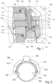
- the illustrated embodiment of an antenna arrangement 100 comprises a dielectric waveguide body 110, which comprises a ceramic material with high permittivity, for example aluminum oxide, zirconium dioxide, or titanium dioxide.
- the waveguide body 110 has a substantially cuboidal basic shape with slightly rounded edges.
- a continuous coupling bore 112 extends through the waveguide body 110 parallel to its largest principal axis of inertia.
- a lateral surface of the waveguide body 110 which surrounds its minimum principal axis of inertia, and a rear end face 114 of the waveguide body 110, whose surface normal runs in the direction of the minimum principal axis of inertia of the waveguide body, have a metallic coating 116, which is prepared using an active solder, wherein a second end face facing away from the first end face 114, which serves as a radiating surface 118, is free of the metallic coating. Furthermore, a circumferential end section of the lateral surface adjacent to the radiating surface is free of the metallic coating 116.
- the antenna arrangement 100 further comprises a metallic carrier body 120, which is made in particular of stainless steel and has a first end section with a cylindrical basic shape. An end face of the first end section has a radiation opening, from which a waveguide chamber 122 extends into the carrier body 120, in which the waveguide body 110 is arranged.
- the waveguide chamber 122 has walls that run essentially parallel to the metallized surfaces of the waveguide body 110.
- the end section of the lateral surface of the waveguide body 110 which is free of metallization, is arranged near the end face of the first end section of the carrier body 120.
- the carrier body 120 has, in a rear end face facing away from the first end face, a filling opening 124 that communicates with the waveguide chamber 122.
- An adhesive is pressed into the waveguide chamber 122 through the filling opening in order to fill a circumferential gap volume between the surfaces of the waveguide body 110 and the walls of the waveguide chamber 122, whereby the gap volume including the gap formed by the non-metallized end section of the lateral surface of the waveguide body 110 up to the Radiating surface 118 is sealed.
- This reliably prevents the penetration of a medium from the first end face of the carrier body 120 into the waveguide chamber 122, in particular to avoid corrosion of the metallic coating 116 of the lateral surface. Should the adhesive in the gap near the first end face become damaged, corrosion will not occur because the end section of the waveguide body 110 is not metallized.
- the carrier body 120 further includes a coaxial coupler bore 126, which extends from an outer surface of the carrier body 120 into the waveguide chamber 122, in alignment with the coupling bore 112 of the waveguide body 110. Furthermore, the carrier body 120 includes a capacitor chamber bore 128, which, also in alignment with the coupling bore 112 of the waveguide body 110, extends from a surface opposite the coaxial coupler bore 126 into the waveguide chamber 122.
- a perforated metallic contact screw 142 is screwed into the coaxial coupler bore 126, pressing its end face against the metallic coating 116, thus establishing a defined galvanic contact between the metallic coating 116 and the carrier body 120.
- a coaxial coupler 130 which has an outer conductor 132 and an inner conductor 134, is guided through the bore of the contact screw 142 and the coupling bore 112 of the waveguide body 110, with the inner conductor 134 extending into the capacitor chamber bore 128.
- the outer conductor 132 is also in galvanic contact with the metallic coating 116 and the carrier body 120 via the contact screw 142.
- the coaxial coupler 130 In order to enable effective capacitive coupling of a microwave into the waveguide body 110 in a frequency range of, for example, approximately 2 GHz to 8 GHz, the coaxial coupler 130 must also be terminated with a suitable capacitance, particularly because the waveguide body has a very high capacitance due to the selected materials.
- the inner conductor 134 of the coaxial coupler is connected to a capacitor 134, which is designed in particular as a printed circuit board capacitor and is arranged in the capacitor chamber bore 128.
- the capacitor 134 is axially clamped in the capacitor chamber bore 128 as follows.
- An annular disk-shaped pressure piece 114 lies with an annular axial Projection on the outer surface of the waveguide body 110.
- the capacitor 134 is supported on the pressure piece 114.
- an insulating disk 148 is arranged, which is axially clamped against the capacitor 134 by a disc spring stack 148 and a clamping screw 144, which is screwed into the capacitor chamber bore 128.
- the disc spring stack 146 ensures that the clamping forces fluctuate only slightly despite different thermal expansion coefficients of the components.
- the pressure piece 114 and the contact screw 142 also each press an O-ring 166, 164 against the outer surface of the waveguide body 110, whereby the capacitor chamber bore 128 and the coaxial coupler bore 126 are sealed against the gap between the waveguide body 110 and the walls of the waveguide chamber 122.
- the carrier body 120 is arranged with the cylindrical end section in an antenna opening 212 of a tube wall 210 of a measuring tube 200, wherein a sealing ring 162 is axially clamped between the tube wall 210 and the carrier body 120.
- the antenna arrangement 100 is covered with an optional protective housing 240, in which (in Fig. 2 shown) signal lines 410 are routed between an operating circuit and the coaxial coupler.
- the measuring arrangement 300 comprises two antenna arrangements 100 and a measuring tube 200 with two opposing antenna openings 212, in each of which one of the antenna arrangements 100 is mounted.
- the measuring arrangement further comprises an operating and measuring circuit 400, which is connected to the two antenna arrangements 100 via two coaxial lines 410.
- the antenna arrangements and coaxial signal lines are also covered by a metallic protective housing 240, which firstly provides additional EMC protection and secondly prevents contamination and mechanical influences on the antenna arrangements and signal lines.
- the operating and measuring circuit is configured to radiate signal sequences of different frequencies in the frequency range of, for example, 2 to 8 GHz via one of the antenna arrangements into a medium located in the measuring tube 200 and to receive them with the other antenna arrangement. Based on the propagation time or attenuation of the signal sequences, the complex permittivity and from this further media properties, such as solid content, are determined.
- Fig. 3 shows the calculated reflection fraction at the radiating surface for various waveguide body materials. Water was assumed as the medium here, and the width of the waveguide body was set at 30 mm. If the waveguide body is made of S-glass with an assumed permittivity of 5.1, wave propagation up to approximately 2.2 GHz is not possible at all, as these frequencies lie below the cutoff frequency. A waveguide body made of Al2O3 is already significantly more suitable than state-of-the-art waveguide bodies, although reflections in the range of s 11 ⁇ -4 dB still occur. With a ZrO2 filling, a consistently good transition of the electromagnetic power into the water is achieved. It can therefore be seen that with the ceramic waveguide bodies used according to the invention, efficient radiation in media with a high water content is achievable for a given antenna geometry.
Landscapes
- Physics & Mathematics (AREA)
- Electromagnetism (AREA)
- Health & Medical Sciences (AREA)
- Life Sciences & Earth Sciences (AREA)
- Chemical & Material Sciences (AREA)
- Analytical Chemistry (AREA)
- Biochemistry (AREA)
- General Health & Medical Sciences (AREA)
- General Physics & Mathematics (AREA)
- Immunology (AREA)
- Pathology (AREA)
- Waveguide Aerials (AREA)
Description
- Die vorliegende Erfindung betrifft eine Messanordnung mit zwei Antennenanordnungen zum Abstrahlung von Mikrowellen. Aus der Literatur ist bekannt, dass aus Laufzeit und Dämpfung der Ausbreitung einer elektromagnetischen Welle in einem Medium auf die komplexwertige Permittivität dieses Materials rückgeschlossen werden kann. Die komplexwertige Permittivität kann wiederum genutzt werden, um Rückschlüsse auf Medieneigenschaften wie z.B. den Wassergehalt zu ziehen.
- Daher sind Messanordnung zum Ermitteln dielektrischer Eigenschaften wie der komplexwertigen Permittivität von Prozessmedien bekannt. Die Offenlegungsschrift
DE 30 38 725 A1 offenbart ein Gerät zur Feuchtebestimmung. Die OffenlegungsschriftenDE 44 26 280 A1 undDE 101 64 107 C1 offenbaren Vorrichtungen zum Messen der Beladung eines Gasstroms mit Feststoffanteilen. Die VeröffentlichungUS 2016 313 259 A1 offenbart eine Temperaturkompensation für die Ermittlung dielektrischer Eigenschaften eines Mediums.WO 1991 005 243 A1 offenbart eine Vorrichtung zum Messen der Konzentration zweier Substanzen. Die OffenlegungsschriftDE 102017 131 269A1 offenbart eine Vorrichtung zur Bestimmung des Fettgehalts von Milch. Die OffenlegungsschriftDE 10 2012 105 281 A1 offenbart ein Füllstandsmessgerät zur Bestimmung des Füllstandes eines Prozessmediums in einem Behältnis mittels eines Laufzeitverfahrens. Dafür weist das Füllstandsmessgerät genau ein Mittel zur Bestimmung des Dielektrizitätszahl auf, welches einen Wellenleiter für ein hochfrequentes Messsignal umfasst, der mit einem Dielektrikum gefüllt ist. - Das Patent
GB 2 293 014 - Die erfindungsgemäße Messanordnung umfasst:
- zwei Antennenanordnungen zum Abstrahlen von Mikrowellen, jeweils umfassend:
- einen dielektrischen Hohlleiterkörper; und
- einen Trägerkörper;
- wobei der dielektrische Hohlleiterkörper zumindest entlang einer umlaufenden Mantelfläche eine elektrisch leitende Oberfläche aufweist,
- wobei der dielektrische Hohlleiterkörper eine elektrisch nichtleitende Abstrahlfläche aufweist,
- wobei der dielektrische Hohlleiterkörper eine Koppleraufnahme aufweist;
- wobei der Trägerkörper den dielektrischen Hohlleiterkörper zumindest entlang der Mantelfläche umgibt,
- wobei der dielektrische Hohlleiterkörper in dem Trägerkörper fixiert ist,
- wobei der Trägerkörper eine Abstrahlöffnung aufweist, wobei die Abstrahlfläche mit der Abstrahlöffnung fluchtet;
- ein Messrohr mit zwei einander gegenüberliegende Antennenöffnungen an welchen jeweils eine der Antennenanordnungen montiert ist,
- eine Mess- und Betriebsschaltung, die mit jeder Antennenanordnung jeweils mittels einer Signalleitung verbunden ist,
- In einer Weiterbildung der Erfindung weist der dielektrische Hohlleiterkörper eine Permittivität von nicht weniger als 8 bei 2 GHz aufweist, insbesondere nicht weniger als 9,5 bei 2 GHz auf.
- In einer Weiterbildung der Erfindung weist der dielektrische Hohlleiterkörper einen keramischen Werkstoff auf, insbesondere Aluminiumoxid, Zirconiumoxid oder Titandioxid.
- In einer Weiterbildung der Erfindung weist der dielektrische Hohlleiterkörper eine Grundform eines Parallelepipeds auf, insbesondere eines Quaders.
- In einer Weiterbildung der Erfindung umfasst die elektrisch leitende Oberfläche des dielektrischen Hohlleiterkörpers eine metallische Beschichtung, wodurch ein gefüllter Hohlleiter gebildet wird.
- In einer Weiterbildung der Erfindung umfasst die metallische Beschichtung ein Aktivhartlot.
- Mit der obigen Materialwahl und der obigen Form kann eine kompakte Antenne realisiert werden, denn die Größe der Antenne bestimmt sich durch die Cutoff-Frequenz fc des gefüllten Hohlleiters. Für den üblicherweise verwendeten Grundmode TE10 eines Rechteckhohlleiters mit den Rechteckseiten a, b gilt a = cd / (2 fc ), wobei für die Ausbreitungsgeschwindigkeit cd im Dielektrikum gilt cd = c0 / εr 1/2. Die Größe der Antenne ist also umgekehrt proportional zur Quadratwurzel der Permittivität des dielektrischen Füllmaterials. Bei einer Permittivität εr,S-Class ≈ 5,2 würde ein derartiger Antennenhohlleiter bei einer Cutoff Frequenz fc = 2 GHz im Querschnitt also eine Mindestbreite von etwa 3,3 cm aufweisen. Wird dagegen ein Dielektrikum mit einer Permittivität εr von mindestens 8 bei 2 GHz verwendet, so beträgt die Mindestbreite nur noch 2,7 cm. Dies ist insoweit vorteilhaft, als dann auch der Durchbruch in dem Trägerkörper auf dieses Maß begrenzt ist. Weiterhin wird mit den gewählten Materialien für das Dielektrikum die Transmission in ein wässriges Medium gegenüber Antennen mit einem Dielektrikum aus Glas erheblich gesteigert.
- In einer Weiterbildung der Erfindung umfasst die Koppleraufnahme eine Bohrung, durch welche sich ein stiftförmiger Koppler, insbesondere Koaxialkoppler erstreckt, der mit einem kapazitiv wirkenden Element terminiert ist.
- In einer Weiterbildung der Erfindung weist das kapazitiv wirkende Element einen Kondensator, beispielsweise in Form eines Platinenstücks mit integriertem Kondensator, eine Koaxialkapazität oder ein offenes Leitungsstück auf.
- In einer Weiterbildung der Erfindung weist der Trägerkörper elektrisch leitende Oberflächen auf, welche den dielektrischen Hohlleiterkörper umgeben.
- In einer Weiterbildung der Erfindung weist der Trägerkörper einen metallischen Werkstoff auf, insbesondere Stahl.
- In einer Weiterbildung der Erfindung weist der Trägerkörper eine Hohlleiterkammer für den dielektrischen Hohlleiterkörper auf, wobei die Hohlleiterkammer Querschnitte aufweist, die parallel zur Abstrahlfläche verlaufen, und die zu mindestens 90% insbesondere 95% der Querschnittsfläche durch den dielektrischen Hohlleiterkörper ausgefüllt sind.
- In einer Weiterbildung der Erfindung ist der dielektrische Hohlleiterkörper mit einem Polymer in der Hohlleiterkammer fixiert.
- In einer Weiterbildung der Erfindung weist der Trägerkörper einen Prozessanschluss auf zum Anschließen der Antennenanordnung an einer Antennenöffnung einer Rohrleitung oder eines Behälters, um die Abstrahlöffnung im Bereich der Antennenöffnung zu positionieren.
- In einer Weiterbildung der Erfindung weist der Werkstoff ein Elastizitätsmodul von nicht weniger als 150 GPa auf.
- Die Erfindung wird nun anhand des in den Zeichnungen dargestellten Ausführungsbeispiels näher erläutert.
- Es zeigt:
-
Fig. 1 : eine räumliche Darstellung eines Ausführungsbeispiels einer erfindungsgemäßen Antennenanordnung; -
Fig. 2 : einen Querschnitt durch ein Ausführungsbeispiel einer erfindungsgemäßen Messanordnung; und -
Fig. 3 : ein Diagramm zum Anteil der reflektierten Leitung an der Grenzfläche zwischen der Antenne und einem wässrigen Medium. - Das in
Fig. 1 dargestellte Ausführungsbeispiel einer erfindungsgemäßen Antennenanordnung 100 umfasst einen dielektrischen Hohlleiterkörper 110, der einen keramischen Werkstoff hoher Permittivität aufweist, beispielsweise Aluminiumoxid, Zirkoniumdioxid oder Titandioxid. Der Hohlleiterkörper 110 weist eine im Wesentlichen quaderförmige Grundform mit leicht abgerundeten Kanten auf. Durch den Hohlleiterkörper 110 erstreckt sich parallel zu seiner größten Hauptträgheitsachse eine durchgehende Koppelbohrung 112. Eine Mantelfläche des Hohlleiterkörpers 110, welche dessen minimale Hauptträgheitsachse umgibt und eine rückseitige Stirnfläche 114 des Hohlleiterkörpers 110, deren Oberflächennormale in Richtung der minimalen Hauptträgheitsachse des Hohlleiterkörpers verläuft, weist eine metallische Beschichtung 116 auf, die mittels eines Aktivlots präpariert ist, wobei eine von der ersten Stirnfläche 114 abgewandte zweite Stirnfläche, die als Abstrahlfäche 118 dient, frei von der metallischen Beschichtung ist. Weiterhin ist ein an die Abstrahlfläche angrenzender, umlaufender Endabschnitt der Mantelfläche frei von der metallischen Beschichtung 116. - Die Antennenanordnung 100 umfasst weiterhin einen metallischen Trägerkörper 120, der insbesondere aus Edelstahl gefertigt ist, und einen ersten Endabschnitt mit einer zylindrischen Grundform aufweist. Eine Stirnfläche des ersten Endabschnitts weist eine Abstrahlöffnung auf, von der sich eine Hohlleiterkammer 122 in den Trägerkörper 120 erstreckt, in welcher der Hohlleiterkörper 110 angeordnet ist, wobei die Hohlleiterkammer 122 Wände aufweist, die im Wesentlichen parallel zu den metallisierten Flächen des Hohlleiterkörpers 110 verlaufen. Der Endabschnitt der Mantelfläche des Hohlleiterkörpers 110, der frei von Metallisierung ist, ist nahe der Stirnfläche, des ersten Endabschnitts des Trägerkörpers120 angeordnet. Der Trägerkörper 120 weist in einer rückseitigen Stirnfläche, welche der ersten Stirnfläche abgewandt ist eine Füllöffnung 124 auf, die mit der Hohlleiterkammer 122 kommuniziert. Wobei durch die Füllöffnung ein Klebstoff in die Hohlleiterkammer 122 eingepresst ist, um ein umlaufendes Spaltvolumen zwischen den Oberflächen des Hohlleiterkörpers 110 und den Wänden der Hohlleiterkammer 122 aufzufüllen, wodurch das Spaltvolumen einschließlich des durch den nicht metallisierten Endabschnitt der Mantelfläche des Hohlleiterkörpers 110 bis zur Abstrahlfläche 118 abgedichtet ist. Damit wird das Eindringen eines Mediums von der ersten Stirnfläche des Trägerkörpers 120 her in die Hohlleiterkammer 122 zuverlässig verhindert, insbesondere um eine Korrosion der metallischen Beschichtung 116 der Mantelfläche zu vermeiden. Sollte der Klebstoff im Spalt nahe der ersten Stirnfläche beschädigt werden so kommt es dennoch nicht zur einsetzenden Korrosion, da der Endabschnitt des Hohlleiterkörpers 110 nicht metallisiert ist.
- Der Trägerkörper 120 weist weiterhin eine Koaxialkopplerbohrung 126 auf, die sich mit der fluchtend mit der Koppelbohrung 112 des Hohlleiterkörpers 110 von einer äußeren Oberfläche des Trägerkörpers 120 in die Hohlleiterkammer 122 erstreckt. Weiterhin weist der Trägerkörper 120 eine Kondensatorkammerbohrung 128 auf, die sich, ebenfalls fluchtend mit der Koppelbohrung 112 des Hohlleiterkörpers 110, von einer der Koaxialkopplerbohrung 126 gegenüberliegenden Oberfläche in die Hohlleiterkammer 122 erstreckt.
- In die Koaxialkopplerbohrung 126 ist eine durchbohrte metallische Kontaktschraube 142 geschraubt, welche mit ihrer Stirnfläche gegen die metallische Beschichtung 116 drückt und so einen definierten galvanischen Kontakt zwischen der metallischen Beschichtung 116 und dem Trägerkörper 120 herstellt. Durch die Bohrung der Kontaktschraube 142 und die Koppelbohrung 112 des Hohlleiterkörpers 110 ist ein Koaxialkoppler 130 geführt, der einen Außenleiter 132 und einen Innenleiter 134 aufweist, wobei der Innenleiter 134 bis in die Kondensatorkammerbohrung 128 hineinragt. Der Außenleiter 132 steht über die Kontaktschraube 142 ebenfalls mit der metallischen Beschichtung 116 und dem Trägerkörper 120 im galvanischen Kontakt.
- Um eine effektive kapazitive Einkopplung einer Mikrowelle in den Hohlleiterkörper 110 in einem Frequenzbereich von beispielsweise etwa 2 GHz bis 8 GHz zu ermöglichen, ist noch der Koaxialkoppler 130 noch mit einer passenden Kapazität zu terminieren, insbesondere deshalb, weil der Hohlleiterkörper aufgrund der gewählten Materialien eine sehr große Kapazität aufweist. Hierzu ist der Innenleiter 134 des Koaxialkopplers mit einem Kondensator 134 verbunden, der insbesondere als Leiterplattenkondensator ausgebildet und in der Kondensatorkammerbohrung 128 angeordnet ist. Der Kondensator 134 ist in der Kondensatorkammerbohrung 128 folgendermaßen axial eingespannt. Ein ringscheibenförmiges Druckstück 114 liegt mit einem ringförmigen axialen Vorsprung an der Mantelfläche des Hohlleiterkörpers 110 an. Der Kondensator 134 stützt sich am Druckstück 114 ab. An der dem Druckstück 114 abgewandten Seite des Kondensators 134 ist eine Isolationsscheibe 148 angeordnet die mit einem Tellerfederstapel 148 und einer Spannschraube 144, die in die Kondensatorkammerbohrung 128 geschraubt ist, gegen den Kondensator 134 axial eingespannt ist. Der Tellerfederstapel 146 bewirkt, dass die Einspannkräfte trotz unterschiedlicher Wärmeausdehnungskoeffizienten der Komponenten nur gering schwanken. Das Druckstück 114 und die Kontaktschraube 142 pressen zudem jeweils einen O-Ring 166, 164 gegen die Mantelfläche des Hohlleiterkörpers 110, wodurch die Kondensatorkammerbohrung 128 und die Koaxialkopplerbohrung 126 gegenüber dem Spalt zwischen dem Hohlleiterköper 110 und den Wänden der Hohlleiterkammer 122 abgedichtet ist.
- Der Trägerkörper 120 ist mit dem zylindrischen Endabschnitt in einer Antennenöffnung 212 einer Rohrwand 210 eines Messrohrs 200 angeordnet, wobei zwischen der Rohrwand 210 und dem Trägerkörper 120 ein Dichtring 162 axial eingespannt ist. Die Antennenanordnung 100 ist mit einem optionalen Schutzgehäuse 240 überdeckt, in dem auch (in
Fig. 2 dargestellte) Signalleitungen 410 zwischen einer Betriebsschaltung und dem Koaxialkoppler geführt sind. - Die erfindungsgemäße Messanordnung 300 umfasst zwei Antennenanordnungen 100 und ein Messrohr 200 mit zwei einander gegenüberliegenden Antennenöffnungen 212, in denen jeweils eine der Antennenanordnungen 100 montiert ist. Weiterhin umfasst die Messanordnung eine Betriebs- und Messschaltung 400, die über zwei Koaxialleitungen 410 mit den beiden Antennenanordnungen 100 verbunden sind. Die Antennenanordnungen und koaxiale Signalleitungen sind noch von einem metallischen Schutzgehäuse 240 überdeckt, welches erstens einen zusätzlichen EMV-Schutz bildet und zweitens Verschmutzung und mechanische Einwirkungen auf die Antennenanordnungen und Signalleitungen verhindert. Die Betriebs- und Messschaltung ist dazu eingerichtet, Signalsequenzen unterschiedlicher Frequenz im Frequenzbereich von beispielsweise 2 bis 8 GHz über eine der Antennenanordnungen in ein im Messrohr 200 befindliches Medium einzustrahlen und mit der Anderen Antennenanordnung zu empfangen. Anhand der Laufzeit bzw. Dämpfung der Signalsequenzen lassen sich die komplexe Permittivität und daraus weitere Medieneigenschaften, wie Feststoffgehalt bestimmen.
- Für die Leistungsfähigkeit der Messanordnung ist es vorteilhaft, wenn eine Reflektion an der Abstrahlfläche 118 des Hohlleiterkörpers möglichst gering ist. Dies kann über das Material des Hohlleiterkörpers 110 beeinflusst werden.
Fig 3 zeigt hierzu den errechneten Reflektionsanteil an der Abstrahlfläche für verschiedene Materialien des Hohlleiterkörpers. Als Medium wurde hier Wasser angenommen, und die Breite des Hohlleiterkörpers wurde mit 30 mm angesetzt. Wenn der Hohlleiterkörper ein S-Glass mit einer angenommenen Permittivität von 5,1 aufweist ist eine Wellenausbreitung bis zu ca. 2,2GHz gar nicht möglich, da diese Frequenzen unterhalb der Cutoff-Frequenz liegen. Ein Hohlleiterkörper aus Al2O3 ist bereits deutlich besser geeignet, als die Hohlleiterkörper des Stands der Technik, wenngleich noch Reflexionen im Bereich von s 11 ≈ -4 dB auftreten. Mit einer ZrO2-Füllung wird ein durchweg guter Übergang der elektromagnetischen Leistung in das Wasser erreicht. Es zeigt sich also, dass mit den erfindungsgemäß verwendeten keramischen Hohlleiterkörpern eine effiziente Abstrahlung in stark wasserhaltige Medien bei gegebener Antennengeometrie erreichbar ist.
Claims (14)
- Messanordnung, umfassend:- zwei Antennenanordnungen (100) zum Abstrahlen von Mikrowellen, jeweils umfassend:- einen dielektrischen Hohlleiterkörper (110); und- einen Trägerkörper (120);wobei der dielektrische Hohlleiterkörper (110) zumindest entlang einer umlaufenden Mantelfläche eine elektrisch leitende Oberfläche aufweist,wobei der dielektrische Hohlleiterkörper (110) eine elektrisch nichtleitende Abstrahlfläche (118) aufweist,wobei der dielektrische Hohlleiterkörper (110) eine Koppleraufnahme (112) aufweist;wobei der Trägerkörper (120) den dielektrischen Hohlleiterkörper (110) zumindest entlang der Mantelfläche umgibt,wobei der dielektrische Hohlleiterkörper (110) in dem Trägerkörper (120) fixiert ist,wobei der Trägerkörper (120) eine Abstrahlöffnung aufweist, wobei die Abstrahlfläche (118) mit der Abstrahlöffnung fluchtet;- ein Messrohr mit zwei einander gegenüberliegende Antennenöffnungen (212) an welchen jeweils eine der Antennenanordnungen (100) montiert ist,- eine Mess- und Betriebsschaltung, die mit jeder Antennenanordnung (100) jeweils mittels einer Signalleitung verbunden ist,dadurch gekennzeichnet, dass der Trägerkörper (120) einen Werkstoff mit einem Elastizitätsmodul von nicht weniger als 50 GPa aufweist.
- Messanordnung nach Anspruch 1, wobei der dielektrische Hohlleiterkörper eine Permittivität von nicht weniger als 8 bei 2 GHz aufweist, insbesondere nicht weniger als 9,5 bei 2 GHz aufweist.
- Messanordnung nach Anspruch 1, wobei der dielektrische Hohlleiterkörper (110) einen keramischen Werkstoff aufweist, insbesondere Aluminiumoxid, Zirkoniumdioxid oder Titandioxid.
- Messanordnung nach Anspruch 1 oder 2, wobei der dielektrische Hohlleiterkörper (110) eine Grundform eines Parallelepipeds aufweist, insbesondere eines Quaders.
- Messanordnung nach einem der vorhergehenden Ansprüche, wobei die elektrisch leitende Oberfläche des dielektrischen Hohlleiterkörpers (110) eine metallische Beschichtung (116) umfasst.
- Messanordnung nach Anspruch 5, wobei die metallische Beschichtung (116) ein Aktivlot oder Aktivhartlot umfasst.
- Messanordnung nach einem der vorhergehenden Ansprüche, wobei die Koppleraufnahme eine Bohrung umfasst, durch welche sich ein stiftförmiger Koppler, insbesondere Koaxialkoppler (130) erstreckt, der mit einem kapazitiv wirkenden Element terminiert ist.
- Messanordnung nach Anspruch 7, wobei das kapazitiv wirkende Element einen Kondensator, beispielsweise in Form eines Platinenstücks mit integriertem Kondensator, eine Koaxialkapazität oder ein offenes Leitungsstück aufweist.
- Messanordnung nach einem der vorhergehenden Ansprüche, wobei der Trägerkörper (120) elektrisch leitende Flächen aufweist, welche den dielektrischen Hohlleiterkörper (110) umgeben.
- Messanordnung nach einem der vorhergehenden Ansprüche, wobei der Trägerkörper (120) einen metallischen Werkstoff aufweist, insbesondere Stahl.
- Messanordnung nach einem der vorhergehenden Ansprüche, wobei der Trägerkörper (120) eine Hohlleiterkammer (122) für den dielektrischen Hohlleiterkörper (110) aufweist, wobei die Hohlleiterkammer (122) Querschnitte aufweist, die parallel zur Abstrahlfläche (118) verlaufen, und die zu mindestens 90% insbesondere 95% der Querschnittsfläche durch den dielektrischen Hohlleiterkörper (110) ausgefüllt sind.
- Messanordnung nach einem der vorhergehenden Ansprüche, wobei der dielektrische Hohlleiterkörper (110) mit einem Polymer in der Hohlleiterkammer fixiert ist.
- Messanordnung nach einem der vorhergehenden Ansprüche, wobei der Trägerkörper (120) einen Prozessanschluss aufweist zum Anschließen der Antennenanordnung (100) an einer Antennenöffnung (212) einer Rohrleitung oder eines Behälters, um die Abstrahlöffnung im Bereich der Antennenöffnung (212) zu positionieren.
- Messanordnung nach einem der vorhergehenden Ansprüche, wobei der Werkstoff ein Elastizitätsmodul von nicht weniger als 150 GPa aufweist.
Applications Claiming Priority (2)
| Application Number | Priority Date | Filing Date | Title |
|---|---|---|---|
| DE102019131504.2A DE102019131504A1 (de) | 2019-11-21 | 2019-11-21 | Antennenanordnung zur Abstrahlung von Mikrowellen und Messanordnung mit mindestens einer solchen Antennenanordnung |
| PCT/EP2020/081431 WO2021099152A1 (de) | 2019-11-21 | 2020-11-09 | Antennenanordnung zur abstrahlung von mikrowellen und messanordnung mit mindestens einer solchen antennenanordnung |
Publications (2)
| Publication Number | Publication Date |
|---|---|
| EP4062158A1 EP4062158A1 (de) | 2022-09-28 |
| EP4062158B1 true EP4062158B1 (de) | 2025-06-11 |
Family
ID=73288582
Family Applications (1)
| Application Number | Title | Priority Date | Filing Date |
|---|---|---|---|
| EP20804208.5A Active EP4062158B1 (de) | 2019-11-21 | 2020-11-09 | Antennenanordnung zur abstrahlung von mikrowellen und messanordnung mit mindestens einer solchen antennenanordnung |
Country Status (5)
| Country | Link |
|---|---|
| US (1) | US12247932B2 (de) |
| EP (1) | EP4062158B1 (de) |
| CN (1) | CN114729905B (de) |
| DE (1) | DE102019131504A1 (de) |
| WO (1) | WO2021099152A1 (de) |
Families Citing this family (6)
| Publication number | Priority date | Publication date | Assignee | Title |
|---|---|---|---|---|
| DE102022129178A1 (de) | 2022-11-04 | 2024-05-08 | Endress+Hauser Flowtec Ag | Messanordnung |
| DE102022132798A1 (de) | 2022-12-09 | 2024-06-20 | Endress + Hauser Flowtec Ag | Verfahren zum kontinuierlichen Bestimmen des Lactose-, Protein- und Fettgehaltes von Milch |
| DE102022133708A1 (de) | 2022-12-16 | 2024-06-27 | Endress+Hauser Flowtec Ag | Messanordnung |
| DE102023112734A1 (de) | 2023-05-15 | 2024-11-21 | Endress+Hauser Flowtec Ag | Verfahren für die Bestimmung eines Feststoffanteils |
| DE102023113838A1 (de) | 2023-05-25 | 2024-11-28 | Endress+Hauser Flowtec Ag | Temperatursensor, Mikrowellensensor und magnetisch-induktives Durchflussmessgerät |
| DE102024137233A1 (de) | 2024-12-11 | 2026-06-11 | Endress + Hauser Flowtec Ag | Verfahren für ein Messgerät und Messgerät |
Family Cites Families (21)
| Publication number | Priority date | Publication date | Assignee | Title |
|---|---|---|---|---|
| DE3038725A1 (de) | 1980-10-14 | 1982-05-19 | Werner Dipl.-Phys. 5000 Köln Heinz | Messgeraet zur kontinuierlichen feuchtebestimmung |
| DD243102A1 (de) * | 1985-12-02 | 1987-02-18 | Nagema Veb K | Einrichtung zur pruefung von flaschen |
| MX173811B (es) | 1989-10-04 | 1994-03-29 | Agar Corp Ltd | Mejoras a medicion de aceite/agua |
| DE4426280A1 (de) | 1994-07-25 | 1996-02-01 | Reich Ernst | Verfahren zum Ermitteln der Beladung eines Gasstroms mit Feststoffanteilen |
| US5473256A (en) | 1994-09-07 | 1995-12-05 | Texaco Inc. | Combination microwave waveguide and pressure barrier |
| DE19641036C2 (de) * | 1996-10-04 | 1998-07-09 | Endress Hauser Gmbh Co | Mit Mikrowellen arbeitendes Füllstandsmeßgerät |
| US5851083A (en) * | 1996-10-04 | 1998-12-22 | Rosemount Inc. | Microwave level gauge having an adapter with a thermal barrier |
| EP0922942A1 (de) | 1997-12-10 | 1999-06-16 | Endress + Hauser GmbH + Co. | Mit Mikrowellen arbeitendes Füllstandsmessgerät mit einem Einsatz aus einem Dielektrikum und Verfahren zur Herstellung des Dielektrikums |
| DE19800306B4 (de) * | 1998-01-07 | 2008-05-15 | Vega Grieshaber Kg | Antenneneinrichtung für ein Füllstandmeß-Radargerät |
| JP3885407B2 (ja) * | 1999-05-10 | 2007-02-21 | 株式会社明電舎 | 汚泥濃度計 |
| DE10023497A1 (de) * | 2000-05-13 | 2001-11-15 | Endress Hauser Gmbh Co | Füllstandsmeßgerät |
| DE10051297A1 (de) * | 2000-10-17 | 2002-04-25 | Endress Hauser Gmbh Co | Füllstandsmeßgerät |
| DE10164107C1 (de) | 2001-12-24 | 2003-09-18 | Promecon Prozess & Messtechnik | Mikrowellen-Messeinrichtung zur Bestimmung der Beladung einer Zweiphasenströmung |
| US6922173B2 (en) * | 2002-02-05 | 2005-07-26 | Theodore R. Anderson | Reconfigurable scanner and RFID system using the scanner |
| US8531337B2 (en) * | 2005-05-13 | 2013-09-10 | Fractus, S.A. | Antenna diversity system and slot antenna component |
| DE102006019191A1 (de) * | 2006-04-21 | 2007-10-25 | Endress + Hauser Gmbh + Co. Kg | Verfahren zur Ermittlung und Überwachung des Füllstands eines Mediums in einem Behälter |
| DE102010031276A1 (de) * | 2010-07-13 | 2012-01-19 | Endress + Hauser Gmbh + Co. Kg | Füllstandsmessgerät zur Ermittlung und Überwachung eines Füllstandes eines im Prozessraum eines Behälters befindlichen Mediums mittels einem Mikrowellen-Laufzeitmessverfahren |
| DE102012105281A1 (de) * | 2012-06-18 | 2013-12-19 | Endress + Hauser Gmbh + Co. Kg | Füllstandsmessgerät und Vorrichtung zur Bestimmung der Dielektrizitätszahl |
| EP3086118A1 (de) | 2015-04-20 | 2016-10-26 | Vayyar Imaging Ltd. | Temperaturkompensierte dielektrische charakterisierung von substanzen |
| WO2019031392A1 (ja) * | 2017-08-09 | 2019-02-14 | シャープ株式会社 | 走査アンテナおよび走査アンテナの製造方法 |
| DE102017131269A1 (de) | 2017-12-22 | 2019-06-27 | Endress+Hauser Flowtec Ag | Verfahren und Vorrichtung zur Milchfettmessung |
-
2019
- 2019-11-21 DE DE102019131504.2A patent/DE102019131504A1/de active Pending
-
2020
- 2020-11-09 CN CN202080080024.6A patent/CN114729905B/zh active Active
- 2020-11-09 US US17/756,189 patent/US12247932B2/en active Active
- 2020-11-09 EP EP20804208.5A patent/EP4062158B1/de active Active
- 2020-11-09 WO PCT/EP2020/081431 patent/WO2021099152A1/de not_active Ceased
Also Published As
| Publication number | Publication date |
|---|---|
| US20220349840A1 (en) | 2022-11-03 |
| DE102019131504A1 (de) | 2021-05-27 |
| EP4062158A1 (de) | 2022-09-28 |
| CN114729905B (zh) | 2026-06-16 |
| WO2021099152A1 (de) | 2021-05-27 |
| CN114729905A (zh) | 2022-07-08 |
| US12247932B2 (en) | 2025-03-11 |
Similar Documents
| Publication | Publication Date | Title |
|---|---|---|
| WO2021099152A1 (de) | Antennenanordnung zur abstrahlung von mikrowellen und messanordnung mit mindestens einer solchen antennenanordnung | |
| EP2698869B1 (de) | Mikrowellenfenster und nach dem Radar-Prinzip arbeitendes Füllstandmesssystem | |
| DE102006019688B4 (de) | Patchantenne mit Keramikscheibe als Abdeckung | |
| DE102007005928B4 (de) | Übertragungsleitungsübergang | |
| DE112017002142B4 (de) | Millimeterwellenband-kommunikationsgerät | |
| EP2435804B1 (de) | Anordnung zur füllstandsmessung mit einem mit mikrowellen arbeitenden füllstandsmessgerät | |
| WO2014006150A1 (de) | Hohlleitereinkopplung, hochfrequenzmodul, füllstandradar und verwendung | |
| EP2565596B1 (de) | Mikrowellensendegerät mit Verguss | |
| DE19800306B4 (de) | Antenneneinrichtung für ein Füllstandmeß-Radargerät | |
| EP2035790A1 (de) | Vorrichtung zur ermittlung und/oder überwachung des füllstandes eines mediums | |
| DE10359867A1 (de) | Einkopplung | |
| WO2010049297A1 (de) | Füllstandsmessgerät | |
| WO2007028775A1 (de) | Vorrichtung zur ermittlung und überwachung des füllstandes eines mediums in einem behälter | |
| EP2752941A1 (de) | Parabolantenne mit einem im Radom integrierten Subreflektor | |
| EP2073312B1 (de) | Antennenkoppler | |
| EP0815954A2 (de) | Schallwandler, insbesondere Ultraschallwandler | |
| EP4047742B1 (de) | Radarmodul | |
| DE2746376C2 (de) | Koppelvorrichtung zwischen einer Koaxialleitung und einem Hohlleiter | |
| DE102014118867A1 (de) | Nach dem Radarprinzip arbeitendes Füllstandmessgerät und Übertragungsstrecke für ein Füllstandmessgerät | |
| EP1774616A1 (de) | Vorrichtung zur übertragung von breitbandigen hochfrequenzsignalen | |
| DE102012112218A1 (de) | Füllstandsmessgerät | |
| WO2025002812A1 (de) | Radarfüllstandsmessgerät zur erfassung von füllständen in behältern | |
| EP3813188B1 (de) | Hohlleiteranordnung und antenne | |
| EP4586396A1 (de) | Radarsensor und hohlleiter-trennstelle | |
| WO2023241959A1 (de) | Schlanker atr-sensor mit mess- und referenzsignal |
Legal Events
| Date | Code | Title | Description |
|---|---|---|---|
| STAA | Information on the status of an ep patent application or granted ep patent |
Free format text: STATUS: UNKNOWN |
|
| STAA | Information on the status of an ep patent application or granted ep patent |
Free format text: STATUS: THE INTERNATIONAL PUBLICATION HAS BEEN MADE |
|
| PUAI | Public reference made under article 153(3) epc to a published international application that has entered the european phase |
Free format text: ORIGINAL CODE: 0009012 |
|
| STAA | Information on the status of an ep patent application or granted ep patent |
Free format text: STATUS: REQUEST FOR EXAMINATION WAS MADE |
|
| 17P | Request for examination filed |
Effective date: 20220420 |
|
| AK | Designated contracting states |
Kind code of ref document: A1 Designated state(s): AL AT BE BG CH CY CZ DE DK EE ES FI FR GB GR HR HU IE IS IT LI LT LU LV MC MK MT NL NO PL PT RO RS SE SI SK SM TR |
|
| DAV | Request for validation of the european patent (deleted) | ||
| DAX | Request for extension of the european patent (deleted) | ||
| RAP3 | Party data changed (applicant data changed or rights of an application transferred) |
Owner name: ENDRESS+HAUSER FLOWTEC AG |
|
| GRAP | Despatch of communication of intention to grant a patent |
Free format text: ORIGINAL CODE: EPIDOSNIGR1 |
|
| STAA | Information on the status of an ep patent application or granted ep patent |
Free format text: STATUS: GRANT OF PATENT IS INTENDED |
|
| INTG | Intention to grant announced |
Effective date: 20241119 |
|
| GRAJ | Information related to disapproval of communication of intention to grant by the applicant or resumption of examination proceedings by the epo deleted |
Free format text: ORIGINAL CODE: EPIDOSDIGR1 |
|
| STAA | Information on the status of an ep patent application or granted ep patent |
Free format text: STATUS: REQUEST FOR EXAMINATION WAS MADE |
|
| GRAP | Despatch of communication of intention to grant a patent |
Free format text: ORIGINAL CODE: EPIDOSNIGR1 |
|
| STAA | Information on the status of an ep patent application or granted ep patent |
Free format text: STATUS: GRANT OF PATENT IS INTENDED |
|
| INTC | Intention to grant announced (deleted) | ||
| INTG | Intention to grant announced |
Effective date: 20250314 |
|
| GRAS | Grant fee paid |
Free format text: ORIGINAL CODE: EPIDOSNIGR3 |
|
| GRAA | (expected) grant |
Free format text: ORIGINAL CODE: 0009210 |
|
| STAA | Information on the status of an ep patent application or granted ep patent |
Free format text: STATUS: THE PATENT HAS BEEN GRANTED |
|
| AK | Designated contracting states |
Kind code of ref document: B1 Designated state(s): AL AT BE BG CH CY CZ DE DK EE ES FI FR GB GR HR HU IE IS IT LI LT LU LV MC MK MT NL NO PL PT RO RS SE SI SK SM TR |
|
| REG | Reference to a national code |
Ref country code: GB Ref legal event code: FG4D Free format text: NOT ENGLISH |
|
| REG | Reference to a national code |
Ref country code: CH Ref legal event code: EP |
|
| REG | Reference to a national code |
Ref country code: DE Ref legal event code: R096 Ref document number: 502020011217 Country of ref document: DE |
|
| REG | Reference to a national code |
Ref country code: IE Ref legal event code: FG4D Free format text: LANGUAGE OF EP DOCUMENT: GERMAN |
|
| P01 | Opt-out of the competence of the unified patent court (upc) registered |
Free format text: CASE NUMBER: APP_26476/2025 Effective date: 20250604 |
|
| REG | Reference to a national code |
Ref country code: NL Ref legal event code: FP |
|
| PG25 | Lapsed in a contracting state [announced via postgrant information from national office to epo] |
Ref country code: ES Free format text: LAPSE BECAUSE OF FAILURE TO SUBMIT A TRANSLATION OF THE DESCRIPTION OR TO PAY THE FEE WITHIN THE PRESCRIBED TIME-LIMIT Effective date: 20250611 Ref country code: FI Free format text: LAPSE BECAUSE OF FAILURE TO SUBMIT A TRANSLATION OF THE DESCRIPTION OR TO PAY THE FEE WITHIN THE PRESCRIBED TIME-LIMIT Effective date: 20250611 |
|
| REG | Reference to a national code |
Ref country code: LT Ref legal event code: MG9D |
|
| PG25 | Lapsed in a contracting state [announced via postgrant information from national office to epo] |
Ref country code: GR Free format text: LAPSE BECAUSE OF FAILURE TO SUBMIT A TRANSLATION OF THE DESCRIPTION OR TO PAY THE FEE WITHIN THE PRESCRIBED TIME-LIMIT Effective date: 20250912 Ref country code: NO Free format text: LAPSE BECAUSE OF FAILURE TO SUBMIT A TRANSLATION OF THE DESCRIPTION OR TO PAY THE FEE WITHIN THE PRESCRIBED TIME-LIMIT Effective date: 20250911 |
|
| PG25 | Lapsed in a contracting state [announced via postgrant information from national office to epo] |
Ref country code: BG Free format text: LAPSE BECAUSE OF FAILURE TO SUBMIT A TRANSLATION OF THE DESCRIPTION OR TO PAY THE FEE WITHIN THE PRESCRIBED TIME-LIMIT Effective date: 20250611 |
|
| PG25 | Lapsed in a contracting state [announced via postgrant information from national office to epo] |
Ref country code: HR Free format text: LAPSE BECAUSE OF FAILURE TO SUBMIT A TRANSLATION OF THE DESCRIPTION OR TO PAY THE FEE WITHIN THE PRESCRIBED TIME-LIMIT Effective date: 20250611 |
|
| PG25 | Lapsed in a contracting state [announced via postgrant information from national office to epo] |
Ref country code: RS Free format text: LAPSE BECAUSE OF FAILURE TO SUBMIT A TRANSLATION OF THE DESCRIPTION OR TO PAY THE FEE WITHIN THE PRESCRIBED TIME-LIMIT Effective date: 20250911 |
|
| PG25 | Lapsed in a contracting state [announced via postgrant information from national office to epo] |
Ref country code: LV Free format text: LAPSE BECAUSE OF FAILURE TO SUBMIT A TRANSLATION OF THE DESCRIPTION OR TO PAY THE FEE WITHIN THE PRESCRIBED TIME-LIMIT Effective date: 20250611 |
|
| PG25 | Lapsed in a contracting state [announced via postgrant information from national office to epo] |
Ref country code: PT Free format text: LAPSE BECAUSE OF FAILURE TO SUBMIT A TRANSLATION OF THE DESCRIPTION OR TO PAY THE FEE WITHIN THE PRESCRIBED TIME-LIMIT Effective date: 20251013 |
|
| PGFP | Annual fee paid to national office [announced via postgrant information from national office to epo] |
Ref country code: NL Payment date: 20251119 Year of fee payment: 6 |
|
| PG25 | Lapsed in a contracting state [announced via postgrant information from national office to epo] |
Ref country code: IS Free format text: LAPSE BECAUSE OF FAILURE TO SUBMIT A TRANSLATION OF THE DESCRIPTION OR TO PAY THE FEE WITHIN THE PRESCRIBED TIME-LIMIT Effective date: 20251011 |
|
| PGFP | Annual fee paid to national office [announced via postgrant information from national office to epo] |
Ref country code: DE Payment date: 20251119 Year of fee payment: 6 |
|
| PGFP | Annual fee paid to national office [announced via postgrant information from national office to epo] |
Ref country code: GB Payment date: 20251121 Year of fee payment: 6 |
|
| PG25 | Lapsed in a contracting state [announced via postgrant information from national office to epo] |
Ref country code: SM Free format text: LAPSE BECAUSE OF FAILURE TO SUBMIT A TRANSLATION OF THE DESCRIPTION OR TO PAY THE FEE WITHIN THE PRESCRIBED TIME-LIMIT Effective date: 20250611 |
|
| PGFP | Annual fee paid to national office [announced via postgrant information from national office to epo] |
Ref country code: IT Payment date: 20251125 Year of fee payment: 6 |
|
| PGFP | Annual fee paid to national office [announced via postgrant information from national office to epo] |
Ref country code: FR Payment date: 20251126 Year of fee payment: 6 |
|
| PG25 | Lapsed in a contracting state [announced via postgrant information from national office to epo] |
Ref country code: CZ Free format text: LAPSE BECAUSE OF FAILURE TO SUBMIT A TRANSLATION OF THE DESCRIPTION OR TO PAY THE FEE WITHIN THE PRESCRIBED TIME-LIMIT Effective date: 20250611 |
|
| PG25 | Lapsed in a contracting state [announced via postgrant information from national office to epo] |
Ref country code: PL Free format text: LAPSE BECAUSE OF FAILURE TO SUBMIT A TRANSLATION OF THE DESCRIPTION OR TO PAY THE FEE WITHIN THE PRESCRIBED TIME-LIMIT Effective date: 20250611 |
|
| PG25 | Lapsed in a contracting state [announced via postgrant information from national office to epo] |
Ref country code: EE Free format text: LAPSE BECAUSE OF FAILURE TO SUBMIT A TRANSLATION OF THE DESCRIPTION OR TO PAY THE FEE WITHIN THE PRESCRIBED TIME-LIMIT Effective date: 20250611 |
|
| PG25 | Lapsed in a contracting state [announced via postgrant information from national office to epo] |
Ref country code: SK Free format text: LAPSE BECAUSE OF FAILURE TO SUBMIT A TRANSLATION OF THE DESCRIPTION OR TO PAY THE FEE WITHIN THE PRESCRIBED TIME-LIMIT Effective date: 20250611 |
|
| PG25 | Lapsed in a contracting state [announced via postgrant information from national office to epo] |
Ref country code: RO Free format text: LAPSE BECAUSE OF FAILURE TO SUBMIT A TRANSLATION OF THE DESCRIPTION OR TO PAY THE FEE WITHIN THE PRESCRIBED TIME-LIMIT Effective date: 20250611 |
|
| REG | Reference to a national code |
Ref country code: DE Ref legal event code: R097 Ref document number: 502020011217 Country of ref document: DE |
|
| PG25 | Lapsed in a contracting state [announced via postgrant information from national office to epo] |
Ref country code: DK Free format text: LAPSE BECAUSE OF FAILURE TO SUBMIT A TRANSLATION OF THE DESCRIPTION OR TO PAY THE FEE WITHIN THE PRESCRIBED TIME-LIMIT Effective date: 20250611 |
|
| PLBE | No opposition filed within time limit |
Free format text: ORIGINAL CODE: 0009261 |
|
| STAA | Information on the status of an ep patent application or granted ep patent |
Free format text: STATUS: NO OPPOSITION FILED WITHIN TIME LIMIT |
|
| REG | Reference to a national code |
Ref country code: CH Ref legal event code: L10 Free format text: ST27 STATUS EVENT CODE: U-0-0-L10-L00 (AS PROVIDED BY THE NATIONAL OFFICE) Effective date: 20260423 |
|
| 26N | No opposition filed |
Effective date: 20260312 |
|
| REG | Reference to a national code |
Ref country code: CH Ref legal event code: H13 Free format text: ST27 STATUS EVENT CODE: U-0-0-H10-H13 (AS PROVIDED BY THE NATIONAL OFFICE) Effective date: 20260623 |
|
| PG25 | Lapsed in a contracting state [announced via postgrant information from national office to epo] |
Ref country code: LT Free format text: LAPSE BECAUSE OF FAILURE TO SUBMIT A TRANSLATION OF THE DESCRIPTION OR TO PAY THE FEE WITHIN THE PRESCRIBED TIME-LIMIT Effective date: 20250611 |
|
| PG25 | Lapsed in a contracting state [announced via postgrant information from national office to epo] |
Ref country code: MC Free format text: LAPSE BECAUSE OF FAILURE TO SUBMIT A TRANSLATION OF THE DESCRIPTION OR TO PAY THE FEE WITHIN THE PRESCRIBED TIME-LIMIT Effective date: 20250611 |
|
| PG25 | Lapsed in a contracting state [announced via postgrant information from national office to epo] |
Ref country code: LU Free format text: LAPSE BECAUSE OF NON-PAYMENT OF DUE FEES Effective date: 20251109 Ref country code: CH Free format text: LAPSE BECAUSE OF NON-PAYMENT OF DUE FEES Effective date: 20251130 |
|
| PG25 | Lapsed in a contracting state [announced via postgrant information from national office to epo] |
Ref country code: SE Free format text: LAPSE BECAUSE OF FAILURE TO SUBMIT A TRANSLATION OF THE DESCRIPTION OR TO PAY THE FEE WITHIN THE PRESCRIBED TIME-LIMIT Effective date: 20250611 |