EP4060711B1 - Steckbarer trennschalter - Google Patents
Steckbarer trennschalter Download PDFInfo
- Publication number
- EP4060711B1 EP4060711B1 EP20888412.2A EP20888412A EP4060711B1 EP 4060711 B1 EP4060711 B1 EP 4060711B1 EP 20888412 A EP20888412 A EP 20888412A EP 4060711 B1 EP4060711 B1 EP 4060711B1
- Authority
- EP
- European Patent Office
- Prior art keywords
- circuit breaker
- opening
- locking
- plug
- closing button
- Prior art date
- Legal status (The legal status is an assumption and is not a legal conclusion. Google has not performed a legal analysis and makes no representation as to the accuracy of the status listed.)
- Active
Links
Images


Classifications
-
- H—ELECTRICITY
- H01—ELECTRIC ELEMENTS
- H01H—ELECTRIC SWITCHES; RELAYS; SELECTORS; EMERGENCY PROTECTIVE DEVICES
- H01H71/00—Details of the protective switches or relays covered by groups H01H73/00 - H01H83/00
- H01H71/10—Operating or release mechanisms
- H01H71/1009—Interconnected mechanisms
-
- H—ELECTRICITY
- H01—ELECTRIC ELEMENTS
- H01H—ELECTRIC SWITCHES; RELAYS; SELECTORS; EMERGENCY PROTECTIVE DEVICES
- H01H1/00—Contacts
- H01H1/12—Contacts characterised by the manner in which co-operating contacts engage
- H01H1/36—Contacts characterised by the manner in which co-operating contacts engage by sliding
-
- H—ELECTRICITY
- H01—ELECTRIC ELEMENTS
- H01H—ELECTRIC SWITCHES; RELAYS; SELECTORS; EMERGENCY PROTECTIVE DEVICES
- H01H71/00—Details of the protective switches or relays covered by groups H01H73/00 - H01H83/00
- H01H71/04—Means for indicating condition of the switching device
-
- H—ELECTRICITY
- H01—ELECTRIC ELEMENTS
- H01H—ELECTRIC SWITCHES; RELAYS; SELECTORS; EMERGENCY PROTECTIVE DEVICES
- H01H71/00—Details of the protective switches or relays covered by groups H01H73/00 - H01H83/00
- H01H71/10—Operating or release mechanisms
- H01H71/50—Manual reset mechanisms which may be also used for manual release
- H01H71/58—Manual reset mechanisms which may be also used for manual release actuated by push-button, pull-knob, or slide
-
- H—ELECTRICITY
- H01—ELECTRIC ELEMENTS
- H01H—ELECTRIC SWITCHES; RELAYS; SELECTORS; EMERGENCY PROTECTIVE DEVICES
- H01H73/00—Protective overload circuit-breaking switches in which excess current opens the contacts by automatic release of mechanical energy stored by previous operation of a hand reset mechanism
- H01H73/02—Details
- H01H73/06—Housings; Casings; Bases; Mountings
- H01H73/08—Plug-in housings
-
- H—ELECTRICITY
- H01—ELECTRIC ELEMENTS
- H01H—ELECTRIC SWITCHES; RELAYS; SELECTORS; EMERGENCY PROTECTIVE DEVICES
- H01H9/00—Details of switching devices, not covered by groups H01H1/00 - H01H7/00
- H01H9/20—Interlocking, locking, or latching mechanisms
-
- H—ELECTRICITY
- H01—ELECTRIC ELEMENTS
- H01H—ELECTRIC SWITCHES; RELAYS; SELECTORS; EMERGENCY PROTECTIVE DEVICES
- H01H71/00—Details of the protective switches or relays covered by groups H01H73/00 - H01H83/00
- H01H71/04—Means for indicating condition of the switching device
- H01H2071/046—Means for indicating condition of the switching device exclusively by position of operating part, e.g. with additional labels or marks but no other movable indicators
-
- H—ELECTRICITY
- H01—ELECTRIC ELEMENTS
- H01H—ELECTRIC SWITCHES; RELAYS; SELECTORS; EMERGENCY PROTECTIVE DEVICES
- H01H71/00—Details of the protective switches or relays covered by groups H01H73/00 - H01H83/00
- H01H71/08—Terminals; Connections
-
- H—ELECTRICITY
- H01—ELECTRIC ELEMENTS
- H01H—ELECTRIC SWITCHES; RELAYS; SELECTORS; EMERGENCY PROTECTIVE DEVICES
- H01H71/00—Details of the protective switches or relays covered by groups H01H73/00 - H01H83/00
- H01H71/10—Operating or release mechanisms
- H01H71/50—Manual reset mechanisms which may be also used for manual release
- H01H71/505—Latching devices between operating and release mechanism
-
- H—ELECTRICITY
- H01—ELECTRIC ELEMENTS
- H01H—ELECTRIC SWITCHES; RELAYS; SELECTORS; EMERGENCY PROTECTIVE DEVICES
- H01H9/00—Details of switching devices, not covered by groups H01H1/00 - H01H7/00
- H01H9/08—Arrangements to facilitate replacement of a switch, e.g. cartridge housing
Definitions
- the present invention relates to the field of low-voltage electrical appliances, in particular to a plug-in circuit breaker.
- the novel plug-in circuit breakers not only can provide various safety protection performance of a circuit breaker for power line and electrical equipment, but also can meet the requirements of various electric appliances on the power supply quality, enabling circuit breakers to be conveniently connected/disconnected to a circuit in a plug-in and plug-out mode.
- the structure of the plug-in circuit breaker has evolved to a wide range, but in the development trend of miniaturizing electrical equipment, it is still necessary to further improve, optimize and upgrade the overall structure and operation mode of the mating circuit breaker.
- the plug-in circuit breaker has obvious advantages in quick installation to the cabinet, the potential safety hazards brought by quickly plugging and plucking plugs to the circuit breaker is further upgraded, including many risks with energized operations, such as, mistakenly installing the circuit breaker into the cabinet in the closing state, the circuit breaker being closed when the circuit breaker is not installed to the destined position, and mistakenly pulling the circuit breaker out of the cabinet in the closing state.
- the locking mechanism of the plug-in circuit breaker of the prior art can only be provided with a locking mechanism for preventing some potential safety hazards in the locking mechanism, for example, preventing the circuit breaker from being inserted into the cabinet under the closing state, rather than preventing the circuit breaker from being pulled out of the cabinet under the closing state.
- the circuit breaker can be prevented from being pulled out of the cabinet in the closing state, during installing the circuit breaker into the cabinet in the opening state, such prior art cannot prevent the circuit breaker from mistakenly closing with user intervention when the circuit breaker is not completely installed in the destined position. Therefore, a set of locking apparatuses cannot be solely used to prevent multiple plug-in operations of the circuit breaker in the closing state (preventing closing before inserting into the cabinet and preventing closing during inserting into the cabinet).
- one set of independent locking apparatuses used for preventing pulling out of the cabinet in the closing state is required to arranged in the same circuit breaker, further another set of independent locking apparatuses used for preventing insertion into the cabinet in the closing state, sometimes even two sets of independent locking apparatuses are required, such as a locking apparatuses used for preventing closing before insertion into the cabinet, and a locking apparatuses used for preventing closing during insertion into the cabinet.
- Multiple sets of locking mechanisms coexist to increase the number of parts of the locking apparatus, and the damage in any one of the sets causes to abandon the apparatus.
- Multiple sets of locking mechanisms require independent space to be installed, so that the circuit breaker cannot be further miniaturized.
- each locking mechanism is independent, the internal movement of each locking apparatus also has independence, the installation positions between the independent locking apparatuses need to be dislocated, so its structure is complex, and its implementation is tedious for functions.
- the independent locking apparatuses are parallel to each other, there will be a plurality of locking protrusions respectively extending out of the window of the circuit breaker, resulting in extreme proneness to misoperation, increase in potential safety hazards, and poor experiences for users.
- the locking mechanism (Fig 9-11) comprises a locking member 6, which can prevent the circuit breaker from being pulled out of the cabinet in the closing state.
- the locking member 6 cannot prevent the circuit breaker from mistakenly closing when the circuit breaker is not completely installed in the destined position.
- the locking member 6 needs to be used with a spring 7, that is, the locking mechanism has a plurality of elements.
- the present invention aims to provide a plug-in circuit breaker with a simple structure and high reliability.
- pulling the opening and closing button enables the plug-in circuit breaker to open, and meanwhile, the locking member rotates to retract the locking protrusion into the circuit breaker housing.
- one end of the opening and closing button close to the locking member is provided with a driving protrusion fitting with the locking driving surface.
- the locking member has the lower portion of one end away from the limiting hole further provided with an activated protruding stand, one side of the activated protruding stand is connected with the locking driving surface, when pulling out the opening and closing button enables the circuit breaker to switch from the closing state to the opening state, the driving protrusion of the opening and closing button pulls the activated protruding stand to enable the opening and closing button to rotate, so that the locking protrusion rotates and retracts into the circuit breaker housing.
- the locking protrusion is a square protruding stand.
- an acute angle is formed between the activated protruding stand and the locking driving surface.
- the plug-in circuit breaker is in the closing state
- the locking driving surface has an included angle ⁇ between itself and the movement direction of the opening and closing button, the included angle ⁇ is less than 15 degrees.
- an operating mechanism drivingly connected with the opening and closing button, a movable contact connected with the operating mechanism, a stationary contact fitting with the movable contact, an arc extinguishing mechanism, an overload protection apparatus, a short-circuit protection mechanism, a wire-outlet end and a wire-inlet end are arranged inside the circuit breaker housing, the opening and closing button and the wire-outlet end are arranged at one end of the circuit breaker housing, the wire-inlet end is arranged at the other end of the circuit breaker housing, the upper side of the circuit breaker housing is provided with the limiting hole, the locking member is rotatably arranged between the opening and closing button and the limiting hole.
- the operating mechanism is arranged on one side of the opening and closing button, and the operating mechanism and the overload protection apparatus are arranged side by side on one side of the opening and closing button and the wire outlet end, the short-circuit protection mechanism is positioned between the operating mechanism and the wire inlet end, the short-circuit protection mechanism and the arc extinguishing mechanism are arranged side by side, and positioned on one side of the operating mechanism and the overload protection apparatus.
- a rotation center is provided in the middle of the locking member, the rotation center is arranged deviating away from one end of the locking protrusion, the locking member has the lower portion of one end away from the limiting hole further provided with an activated protruding stand, one side of the activated protruding stand is connected with the locking driving surface, one end of said opening and closing buttonclose to said locking member is provided with a driving protrusion, said driving protrusion and the locking driving surface always keep slidable fit with each other.
- just making a locking member fit with a opening and closing button enables a plurality of locking functions, such as: (1) when the circuit breaker is closed outside the cabinet, it cannot be installed to the operating position, thereby avoiding risks with energized operations; (2) during installing the plug-in circuit breaker to the installation-position of the cabinet, it cannot complete the closing action when it is not installed to the operating position, thereby avoiding risks with energized operations; (3) when the plug-in circuit breaker is installed to the correct operating position of the cabinet, the opening and closing button can normally realize closing and opening operations, but in the closing state, the locking apparatus can lock the plug-in circuit breaker in the operating position, so that the plug-in circuit breaker cannot be easily pulled out, avoiding the energized plug-in and plug-out operations, and greatly improving the use safety of the plug-in circuit breaker, furthermore it has a very simple structure and low costs.
- plug-in circuit breaker according to the present invention as follows in combination with the examples.
- the plug-in circuit breaker of the present invention is not limited to the description of the following embodiments.
- the breaker includes the circuit breaker housing 3.
- the opening and closing button 1 used for actuating the circuit breaker to open and close is arranged on the circuit breaker housing 3, and the operating mechanism 5 drivingly connected with the opening and closing button 1, the movable contact connected with the operating mechanism, the stationary contact fitting with the movable contact, the arc extinguishing mechanism 8, the wire-outlet end 4 and the wire-inlet end 9 are arranged inside the circuit breaker housing 3.
- the opening and closing button 1 and the wire-outlet end 4 are arranged at one end of the circuit breaker housing 3, and the wire-inlet end 9 is arranged at the other end of the circuit breaker housing 3.
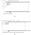
- a locking apparatus is further arranged in the plug-in circuit breaker, the limiting hole 31 fitting with the locking apparatus is arranged on the circuit breaker housing 3 of the plug-in circuit breaker, and the cabinet limiting hole 901 corresponding to the limiting hole 31 of the plug-in circuit breaker is arranged on the installation position 900 of the cabinet.
- the limiting hole 31 of the plug-in circuit breaker corresponds to the cabinet limiting hole 901
- the limiting hole 31 of the plug-in circuit breaker is misaligned with the cabinet limiting hole 901, as it pertains to the prior art in the art, details for it are not described herein again.
- the plug-in circuit breaker of the present invention includes the circuit breaker housing 3 provided with the limiting hole 31, the opening and closing button 1 and the locking apparatus.
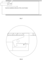
- the plug-in circuit breaker has a main improvement on that the locking apparatus includes the locking member 2 installed inside the plug-in circuit breaker, and the locking member 2 is rotatably arranged inside the circuit breaker housing 3, and has the upper portion provided with the locking protrusion 22 fitting with the limiting hole 31, and the lower portion provided with the locking driving surface 23 fitting with the opening and closing button 1.
- Pressing the opening and closing button 1 enables the opening and closing button 1 to abut against the locking driving surface 23 of the locking member 2, thus the locking protrusion 22 of the driving locking member 2 rotates to the limiting hole 31 of the circuit breaker housing 3.
- the locking protrusion 22 can extend out of the limiting hole 31, at this time the opening and closing button 1 jacks up the locking driving surface 23 to enable the locking protrusion to extend out of the limiting hole 31, and the plug-in circuit breaker is closed.
- the locking driving surface 23 limits the opening and closing button 1, so that the opening and closing button 1 cannot press to the destined position, and the plug-in circuit breaker cannot be closed.
- the plug-in circuit breaker has been installed to the operating position, the limiting hole 31 of the plug-in circuit breaker corresponds to the cabinet limiting hole 901, at the moment, pressing the opening and closing button enables the opening and closing button 1 to slidably fit with the locking driving surface 23, butting against the locking driving surface 23 of the locking member 2 enables the locking protrusion 22 of the driving locking member 2 to rotate towards the limiting hole 31 of the circuit breaker housing 3, so that the locking protrusion 22 can extend out of the limiting hole 31 and the cabinet limiting hole 901.
- the opening and closing button 1 jacks up the locking driving surface 23, thus the opening and closing button 1 can continue to press the closing position, so that the plug-in circuit breaker is closed.
- the plug-in circuit breaker is not installed to the operating position, and the limiting hole 31 of the plug-in circuit breaker is misaligned with the cabinet limiting hole 901, thus the limiting hole 31 of the plug-in circuit breaker is shielded by the sheet metal part of the installation position 900 of the cabinet, so that the locking protrusion 22 of the locking member 2 is limited by the cabinet, and cannot rotate from the limiting hole 31 to extend out of the circuit breaker.
- pressing the opening and closing button 1 does not enable the opening and closing button 1 to fully jack up the locking driving surface 23 as the locking protrusion 22 is limited by the cabinet sheet metal part, thus the locking driving surface 23 is obliquely arranged in the movement direction of the opening and closing button 1.
- Limiting the opening and closing button 1 does not enable the opening and closing button 1 to move into the inside of the circuit breaker, nor can press to the destinated position, so that the plug-in circuit breaker cannot be closed in the installation position of the cabinet, avoiding energized operations.
- the plug-in circuit breaker is closed outside the cabinet, pressing the opening and closing button 1 enables the closing and opening 1 to move toward the inside of the circuit breaker, thus the opening and closing button 1 abuts against the locking driving surface 23 of the locking member 2, so as to actuate the locking protrusion 22 of the locking member 2 rotate toward the limiting hole 31 of the circuit breaker housing 3.
- the opening and closing button 1 jacks up the locking driving surface 23, so that the locking protrusion 22 extends out of the limiting hole 31 and is exposed outside the circuit breaker, and the opening and closing button 1 can continue to press to the closing position, so as to enable close the plug-in circuit breaker.
- the locking protrusion 22 protrudes from the limiting hole 31 and surmounts the installation position 900 of the cabinet, and the locking protrusion 22 abuts against the cabinet sheet metal part of the installation position 900, so that the plug-in circuit breaker cannot be inserted into the operating position of the installation position of the cabinet, avoiding energized operations.
- the locking member 2 is provided with the rotating center 24, and the circuit breaker housing 3 is provided with the limiting hole 31.
- the locking protrusion 22 arranged correspondingly to the limiting hole 31 is arranged on one end away from the rotating center and close to the upper portion of the locking member 2, and the lower portion of the locking member 2 away from the limiting hole 31 is provided with the locking driving surface 23 fitting with the opening and closing button 1.
- the locking member 2 can rotate around the rotation center 24 toward one side to enable the locking protrusion 22 to extend out of the limiting hole 31 or rotate around the rotation center 24 toward the other side to enable the locking protrusion 22 to retract into the circuit breaker housing 3.
- Pressing the opening and closing button 1 enables the opening and closing button 1 to abut against the locking driving surface 23 of the locking member 2, so that the opening and closing button 1 and the locking driving surface 23 always keep slidable fit with each other, and the locking protrusion 22 of the driving locking member 2 rotates to the limiting hole 31 of the circuit breaker housing 3.
- the opening and closing button 1 jacks up the locking driving surface 23, and enables the plug-in circuit breaker to be closed. After the circuit breaker is closed, the opening and closing button 1 limits the locking member 2, so that the locking member 2 cannot rotate in the reverse direction.
- the locking protrusion 22 is a square protruding stand, when the locking protrusion 22 extends out of the limiting hole 31, the two side edges of the square protruding stand are parallel to the two side walls of the limiting hole 31, thereby effectively preventing the plug-in circuit breaker from being inserted into the installation position when it is closed outside the cabinet, and the plug-in circuit breaker from being pulled out after it is installed to the operating position of the cabinet in the closing state.
- the locking protrusion 22 is not limited to a square protruding stand, or may be a round boss, or other structures such as a T-shaped protrusion.
- the locking driving surface 23 is a flat surface, in this way, when the opening and closing button 1 is in slidable fit with the locking driving surface 23, so that it can move smoothly.
- the locking driving surface 23 may also be an arc-shaped surface, or have some grooves or protrusions.
- the closing and opening button 1 is in slidable fit with the locking driving surface 23 by one end thereof, preferably, one end of the opening and closing button 1 close to the locking member 2 is provided with the driving protrusion 12 fitting with the locking driving surface 23, and the driving protrusion 12 jacks up the locking driving surface 23 during closing.
- the driving protrusion 12 is positioned right below the locking protrusion 22 and the limiting hole 31, so as to achieve a better supporting and limiting effect.
- one end of the opening and closing button 1 may not be provided with the driving protrusion 12, and the right-angle side edge of one end of the opening and closing button 1 is directly in slidable fit with the locking driving surface 23, or a round corner is arranged on the right-angle side edge of one end thereof to fit with it.
- the locking member 2 rotates to retract the locking protrusion 22 into the circuit breaker housing.
- the rotation center 24 is provided in the middle of the locking member 2, the rotation center 24 deviates away from one end of the locking protrusion 22, the locking member 2 has the upper portion of one end close to the limiting hole 31 provided with the locking protrusion 22 corresponding to the limiting hole 31, the lower portion away from the limiting hole 31 provided with the locking driving surface 23 fitting with the opening and closing button 1, and the lower portion of one end away from the limiting hole 31 further provided with the activated protruding stand 21.
- One side of the activated protruding stand 21 is connected with the locking driving surface 23, and the driving protrusion 12 is arranged on one side, close to the locking member 2, of one end of the opening and closing button 1, thus pressing the opening and closing button 1 enables the opening and closing button 1 to fit with the locking driving surface 23 by the driving protrusion 12, so as to jack up the opening and closing button 1, enabling the locking protrusion 22 to extend out of the limiting hole 31, and the circuit breaker is closed .
- pulling out the opening and closing button 1 enables the circuit breaker to switch from the closing state to the opening state.
- pulling out the opening and closing button 1 first enables the opening and closing button 1 to slidably fit with the locking driving surface 23 by means of the driving protrusion 12, then enables the plug-in circuit breaker to open, thus the driving protrusion 12 moves to fit with the activated protruding stand 21 of the locking member 2.
- Pulling the activated protruding stand 21 enables the opening and closing button 1 to rotate clockwise, thus the locking protrusion 22 rotates and retracts into the circuit breaker housing 3, so that the plug-in circuit breaker can be detached from the operating position when the plug-in circuit breaker is in the opening state.
- the opening and closing button 1 actuates the circuit breaker to close and open, the opening and closing button 1 and the locking driving surface 23 are always in contact and slidable fit with each other.
- one end of the opening and closing button 1 extending into the circuit breaker is the driving end 11, the button limiting groove 13 is arranged on one side, close to the locking member 2, of the driving end 11 of the opening and closing button 1, the driving protrusion 12 is arranged on one side, close to the locking protrusion 22, of the button limiting groove 13, and the activated protruding stand 21 moves inside the region of the button limiting groove 13.
- the driving protrusion 12 of the opening and closing button 1 is positioned right below the locking protrusion 22 and the limiting hole 31, the activated protruding stand 21 of the locking member 2 obliquely abuts against the side of the button limiting groove 13 away from the locking protrusion 22, so that the locking member 2 is limited to rotate clockwise, thus retracts into the circuit breaker housing 3.
- the activated protruding stand 21 of the locking member 2 fits with the driving protrusion 12, close to on one side of the locking protrusion 22, of the button limiting groove 13, thus pulling the locking member 2 to rotate clockwise enables the locking protrusion 22 to retract into the circuit breaker housing 3.
- the activated protruding stand 21 and/or the driving protrusion 12 may not be arranged in the circuit breaker.
- pulling out the opening and closing button 1 has enabled the circuit breaker to open, pulling out the opening and closing button 1 no longer limits the locking member 2, the weight of one end of the locking protrusion 22 arranged on the locking member 2 is greater than the other end, and the locking protrusion 22 rotates and retracts into the circuit breaker housing under the action of gravity.
- the locking member 2 has an eccentric structure, and the rotation center 24 of the locking member 2 is arranged deviating away from one end of the locking protrusion 22.
- the elastic member connected with the locking member 2 is configured to actuate the locking member 2 to rotate in the retraction direction of the locking protrusion 22 into the circuit breaker housing, the elastic member may be a torsion spring or a pressure spring.
- this solution not only raises the number of parts, but also increases the strength of pressing the opening and closing button 1.
- the locking member 2 has the middle portion rotatably installed inside the circuit breaker housing 3, the upper portion of one end close to the limiting hole 31 provided with a locking protrusion 22, and the lower portion of one end away from the limiting hole 31 provided with the locking driving surface 23 fitting with the opening and closing button 1.
- the lower portion of the other end of the locking member 2 is further provided with the activated protruding stand 21, one side of which is connected with the locking driving surface 23, and an acute angle is formed between the activated protruding stand 21 and the locking driving surface 23.
- the locking driving surface 23 has an included angle ⁇ between itself and the movement direction of the opening and closing button 1, that is, an included angle ⁇ between itself and the horizontal direction, and the included angle ⁇ is less than 15 degrees.
- the driving protrusion 12 may be positioned right below the locking protrusion 22 and the limiting hole 31, and two side edges of the square protruding stand are parallel to two side walls of the limiting hole 31.
- the breaker includes the circuit breaker housing 3.
- the opening and closing button 1 is arranged on the circuit breaker housing 3, and the operating mechanism 5 drivingly connected with the opening and closing button 1, the movable contact connected with the operating mechanism, the stationary contact fitting with the movable contact, the arc extinguishing mechanism 8, the wire-outlet end 4, the wire-inlet end 9 and the locking apparatus of the present invention are arranged inside the circuit breaker housing 3.
- the opening and closing button 1 and the wire-outlet end 4 are arranged at one end of the circuit breaker housing 3, and the wire-inlet end 9 is arranged at the other end of the circuit breaker housing 3.
- the front panel of the plug-in circuit breaker is positioned on the left side, the plug-in circuit breaker is inserted between the two cabinet sheet metal parts 4 in the insertion installation direction F (shown in FIG. 7 ) of the circuit breaker, and can be pulled out of the cabinet in the reverse insertion installation direction F of the circuit breaker.
- the upper side of the circuit breaker housing 3 is provided with the limiting hole 31, and the locking apparatus includes the locking member 2, which is rotatably arranged between the opening and closing button 1 and the limiting hole 31.
- the operating mechanism 5 is arranged on one side of the opening and closing button 1, and the operating mechanism 5 and the overload protection apparatus 6 are arranged side by side on one side of the opening and closing button 1 and the wire outlet end 4.
- the wire-outlet end 4 is arranged below the opening and closing button 1 and on the left side inside the circuit breaker, the wire inlet end 9 is arranged on the right side inside the circuit breaker, the operating mechanism 5 is arranged on the right side of the opening and closing button 1.
- the overload protection apparatus 6 is arranged below the operating mechanism 5 and on the right side of the wire-outlet end 4, the short-circuit protection mechanism 7 is arranged on the right side of the operating mechanism 5 and the left side of the wire-inlet end 9, the arc extinguishing mechanism 8 is arranged below the short-circuit protection mechanism 7, the right side of the overload protection apparatus 6 and the left side of the wire-inlet end 9.
Landscapes
- Breakers (AREA)
- Switch Cases, Indication, And Locking (AREA)
Claims (12)
- Einsteckstromkreisunterbrecher, der ein Stromkreisunterbrechergehäuse (3), das dazu gestaltet ist, in einen Schrank eingesetzt zu werden und mit einem Beschränkungsloch (31) versehen ist, und einen Öffnungs- und Schließknopf (1) aufweist, wobei der Stromkreisunterbrecher ferner ein Sperrelement (2) umfasst, wobei das Sperrelement (2) drehbar innerhalb des Stromkreisunterbrechergehäuses (3) angeordnet ist und einen oberen Abschnitt nahe bei dem Beschränkungsloch (31) hat, der mit einem Sperrvorsprung (22) versehen ist, der mit dem Beschränkungsloch (31) zusammenpasst, und einen unteren Abschnitt hat, der mit einer Sperrantriebsfläche (23) versehen ist, die mit dem Öffnungs- und Schließknopf (1) zusammenpasst;
dadurch gekennzeichnet, dass ein Pressen des Öffnungs- und Schließknopfes (1) es dem Öffnungs- und Schließknopf (1) ermöglicht, gegen die Sperrantriebsfläche (23) des Sperrelements (2) in Anlage zu kommen, und somit der Sperrvorsprung (22) des Antriebssperrelements (2) zu dem Beschränkungsloch (31) des Stromkreisunterbrechergehäuses (3) dreht, wenn das Beschränkungsloch (31) nicht durch den Schrank abgeschirmt ist, der Öffnungs- und Schließknopf (1) die Sperrantriebsfläche (23) anhebt, um es dem Sperrvorsprung (22) zu ermöglichen, sich aus dem Beschränkungsloch (31) heraus zu erstrecken, und der Einsteckstromkreisunterbrecher geschlossen ist, wenn das Beschränkungsloch (31) durch den Schrank abgeschirmt ist, sodass der Sperrvorsprung (22) sich nicht aus dem Beschränkungsloch (31) heraus erstrecken kann und somit die Sperrantriebsfläche (23) den Öffnungs- und Schließknopf (1) beschränkt, sodass der Öffnungs- und Schließknopf (1) nicht zu der bestimmten Position gepresst werden kann und der Einsteckstromkreisunterbrecher nicht geschlossen werden kann. - Einsteckstromkreisunterbrecher gemäß Anspruch 1, wobei ein Ziehen des Öffnungs- und Schließknopfes (1) es dem Einsteckstromkreisunterbrecher ermöglicht, sich zu öffnen und währenddessen sich das Sperrelement (2) zum Zurückziehen des Sperrvorsprungs (22) in das Stromkreisunterbrechergehäuse dreht.
- Einsteckstromkreisunterbrecher gemäß Anspruch 1, wobei ein Ende des Öffnungs- und Schließknopfes (1) nahe bei dem Sperrelement (2) mit einem Antriebsvorsprung (12) versehen ist, der mit der Sperrantriebsfläche (23) zusammenpasst.
- Einsteckstromkreisunterbrecher gemäß Anspruch 3, wobei das Sperrelement (2) den unteren Abschnitt eines Endes, das von dem Beschränkungsloch (31) entfernt ist, ferner mit einem aktivierten vorstehenden Ständer (21) versehen hat, eine Seite des aktivierten vorstehenden Ständers (21) mit der Sperrantriebsfläche (23) verbunden ist, wenn ein Herausziehen des Öffnungs- und Schließknopfes (1) es dem Stromkreisunterbrecher ermöglicht, von dem Schließzustand zu dem Öffnungszustand zu schalten, der Antriebsvorsprung (12) des Öffnungs- und Schließknopfes (1) den aktivierten vorstehenden Ständer (21) zieht, um es dem Öffnungs- und Schließknopf (1) zu ermöglichen, sich zu drehen, sodass sich der Sperrvorsprung (22) dreht und sich in das Stromkreisunterbrechergehäuse (3) zurückzieht.
- Einsteckstromkreisunterbrecher gemäß Anspruch 4, wobei ein Ende des Öffnungs- und Schließkopfes (1), das sich in den Stromkreisunterbrecher erstreckt, ein Antriebsende (11) ist, eine Knopfbeschränkungsnut (13) an einer Seite angeordnet ist, nahe bei dem Sperrelement (2), des Antriebsendes (11) des Öffnungs- und Schließknopfes (1), der Antriebsvorsprung (12) an einer Seite angeordnet ist, nahe bei dem Sperrvorsprung (22), der Knopfbeschränkungsnut (13), wenn der Stromkreisunterbrecher in dem Schließzustand ist, der aktivierte vorstehende Ständer (21) des Sperrelements (2) schräg gegen die Seite der Knopfbeschränkungsnut (13) Anlage ist, die von dem Sperrvorsprung (22) entfernt ist.
- Einsteckstromkreisunterbrecher gemäß Anspruch 1, wobei der Sperrvorsprung (22) ein viereckiger vorstehender Ständer ist.
- Einsteckstromkreisunterbrecher gemäß Anspruch 3, wobei, wenn der Einsteckstromkreisunterbrecher in dem Schließzustand ist, der Antriebsvorsprung (12) direkt unter dem Sperrvorsprung (22) und dem Beschränkungsloch (31) positioniert ist.
- Einsteckstromkreisunterbrecher gemäß Anspruch 4, wobei ein spitzer Winkel zwischen dem aktivierten vorstehenden Ständer (21) und der Sperrantriebsfläche (23) ausgebildet ist.
- Einsteckstromkreisunterbrecher gemäß Anspruch 1, wobei der Einsteckstromkreisunterbrecher in dem Schließzustand ist, die Sperrantriebsfläche (23) einen eingeschlossenen Winkel α zwischen sich selbst und der Bewegungsrichtung des Öffnungs- und Schließknopfes (1) hat, der eingeschlossene Winkel α weniger als 15 Grad ist.
- Einsteckstromkreisunterbrecher gemäß Anspruch 1, wobei ein Betätigungsmechanismus (5), der antreibbar mit dem Öffnungs- und Schließknopf (1) verbunden ist, ein bewegbarer Kontakt, der mit dem Betätigungsmechanismus (5) verbunden ist, ein stationärer Kontakt, der mit dem bewegbaren Kontakt zusammenpasst, ein Bogenauslöschungsmechanismus (8), ein Überlastschutzgerät (6), ein Kurzschlussschutzmechanismus (7), ein Drahtauslassende (4) und ein Drahteinlassende (9) innerhalb des Stromkreisunterbrechergehäuses (3) angeordnet sind, der Öffnungs- und Schließknopf (1) und das Drahtauslassende (4) an einem Ende des Stromkreisunterbrechergehäuses (3) angeordnet sind, das Drahteinlassende (9) an dem anderen Ende des Stromkreisunterbrechergehäuses (3) angeordnet ist, die obere Seite des Stromkreisunterbrechergehäuses (3) mit dem Beschränkungsloch (31) versehen ist, das Sperrelement (2) drehbar zwischen dem Öffnungs- und Schließknopf (1) und dem Beschränkungsloch(31) angeordnet ist.
- Einsteckstromkreisunterbrecher gemäß Anspruch 10, wobei der Betätigungsmechanismus (5) an einer Seite des Öffnungs- und Schließknopfes (1) angeordnet ist und der Betätigungsmechanismus (5) und das Überlastschutzgerät (6) nebeneinander an einer Seite des Öffnungs- und Schließknopfes (1) und des Drahtauslassendes (4) angeordnet sind, der Kurzschlussschutzmechanismus (7) zwischen dem Betätigungsmechanismus (5) und dem Drahteinlassende (9) positioniert ist, der Kurzschlussschutzmechanismus (7) und der Bogenauslöschungsmechanismus (8) nebeneinander angeordnet sind und an einer Seite des Betätigungsmechanismus (5) und des Überlastschutzgerätes (6) positioniert sind.
- Einsteckstromkreisunterbrecher gemäß Anspruch 1, wobei ein Drehzentrum (24) in der Mitte des Sperrelements (2) vorgesehen ist, das Drehzentrum (24) von einem Ende des Sperrvorsprungs (22) weg abweichend angeordnet ist, das Sperrelement (2) den unteren Abschnitt eines Endes, das von dem Beschränkungsloch (31) entfernt ist, ferner mit einem aktivierten vorstehenden Ständer (21) versehen hat, eine Seite des aktivierten vorstehenden Ständers (21) mit der Sperrantriebsfläche (23) verbunden ist, ein Ende des Öffnungs- und Schließknopfes (1) nahe bei dem Sperrelement (2) mit einem Antriebsvorsprung (12) versehen ist, der Antriebsvorsprung (12) und die Sperrantriebsfläche (23) immer ein gleitbares Zusammenpassen miteinander beibehalten.
Applications Claiming Priority (2)
| Application Number | Priority Date | Filing Date | Title |
|---|---|---|---|
| CN201911121721.7A CN111489937B (zh) | 2019-11-15 | 2019-11-15 | 插入式断路器 |
| PCT/CN2020/128879 WO2021093879A1 (zh) | 2019-11-15 | 2020-11-14 | 插入式断路器 |
Publications (4)
| Publication Number | Publication Date |
|---|---|
| EP4060711A1 EP4060711A1 (de) | 2022-09-21 |
| EP4060711A4 EP4060711A4 (de) | 2023-11-29 |
| EP4060711C0 EP4060711C0 (de) | 2025-05-07 |
| EP4060711B1 true EP4060711B1 (de) | 2025-05-07 |
Family
ID=71797778
Family Applications (1)
| Application Number | Title | Priority Date | Filing Date |
|---|---|---|---|
| EP20888412.2A Active EP4060711B1 (de) | 2019-11-15 | 2020-11-14 | Steckbarer trennschalter |
Country Status (7)
| Country | Link |
|---|---|
| US (1) | US12014891B2 (de) |
| EP (1) | EP4060711B1 (de) |
| JP (1) | JP7659554B2 (de) |
| CN (1) | CN111489937B (de) |
| AU (1) | AU2020384177B2 (de) |
| BR (1) | BR112022009378A2 (de) |
| WO (1) | WO2021093879A1 (de) |
Families Citing this family (3)
| Publication number | Priority date | Publication date | Assignee | Title |
|---|---|---|---|---|
| CN111477512B (zh) * | 2019-11-15 | 2025-01-28 | 浙江正泰电器股份有限公司 | 插入式断路器 |
| CN111489937B (zh) | 2019-11-15 | 2025-09-02 | 浙江正泰电器股份有限公司 | 插入式断路器 |
| CN116246914A (zh) * | 2021-12-08 | 2023-06-09 | 上海良信电器股份有限公司 | 一种操作机构及断路器 |
Family Cites Families (13)
| Publication number | Priority date | Publication date | Assignee | Title |
|---|---|---|---|---|
| DE19653266A1 (de) * | 1996-12-20 | 1998-06-25 | Abb Patent Gmbh | Installationsschaltgerät |
| JP3861401B2 (ja) * | 1997-09-19 | 2006-12-20 | 富士電機機器制御株式会社 | 回路遮断器 |
| JP3853245B2 (ja) * | 2002-04-12 | 2006-12-06 | 寺崎電気産業株式会社 | プラグイン型回路遮断器 |
| US6480079B1 (en) * | 2002-04-25 | 2002-11-12 | Texas Instruments Incorporated | Electrical circuit breaker device |
| US9564280B2 (en) * | 2014-08-01 | 2017-02-07 | Schneider Electric USA, Inc. | Panel board to circuit breaker positive retention interlock |
| CN106710982B (zh) * | 2015-07-16 | 2018-09-21 | 上海良信电器股份有限公司 | 断路器操作机构的控制机构 |
| CN207624637U (zh) * | 2017-10-26 | 2018-07-17 | 上海良信电器股份有限公司 | 一种插入式小型断路器 |
| CN107833799B (zh) * | 2017-10-26 | 2024-09-20 | 上海良信电器股份有限公司 | 一种插入式断路器的固定及解锁机构 |
| CN109585233B (zh) * | 2018-12-28 | 2024-05-14 | 浙江正泰电器股份有限公司 | 小型断路器 |
| CN209487450U (zh) * | 2018-12-28 | 2019-10-11 | 浙江正泰电器股份有限公司 | 小型断路器 |
| CN109686626B (zh) * | 2018-12-28 | 2024-05-07 | 浙江正泰电器股份有限公司 | 小型断路器 |
| CN211350531U (zh) * | 2019-11-15 | 2020-08-25 | 浙江正泰电器股份有限公司 | 插入式断路器 |
| CN111489937B (zh) * | 2019-11-15 | 2025-09-02 | 浙江正泰电器股份有限公司 | 插入式断路器 |
-
2019
- 2019-11-15 CN CN201911121721.7A patent/CN111489937B/zh active Active
-
2020
- 2020-11-14 AU AU2020384177A patent/AU2020384177B2/en active Active
- 2020-11-14 EP EP20888412.2A patent/EP4060711B1/de active Active
- 2020-11-14 US US17/776,374 patent/US12014891B2/en active Active
- 2020-11-14 BR BR112022009378A patent/BR112022009378A2/pt unknown
- 2020-11-14 WO PCT/CN2020/128879 patent/WO2021093879A1/zh not_active Ceased
- 2020-11-14 JP JP2022527236A patent/JP7659554B2/ja active Active
Also Published As
| Publication number | Publication date |
|---|---|
| EP4060711A4 (de) | 2023-11-29 |
| AU2020384177B2 (en) | 2023-05-18 |
| CN111489937A (zh) | 2020-08-04 |
| EP4060711C0 (de) | 2025-05-07 |
| AU2020384177A1 (en) | 2022-05-26 |
| JP2023502906A (ja) | 2023-01-26 |
| JP7659554B2 (ja) | 2025-04-09 |
| EP4060711A1 (de) | 2022-09-21 |
| WO2021093879A1 (zh) | 2021-05-20 |
| BR112022009378A2 (pt) | 2022-08-09 |
| CN111489937B (zh) | 2025-09-02 |
| US12014891B2 (en) | 2024-06-18 |
| US20220415600A1 (en) | 2022-12-29 |
Similar Documents
| Publication | Publication Date | Title |
|---|---|---|
| US12159764B2 (en) | Plug-in circuit breaker | |
| EP4060711B1 (de) | Steckbarer trennschalter | |
| CN109637907B (zh) | 小型断路器 | |
| EP4060708B1 (de) | Steckbarer trennschalter | |
| CN110400727B (zh) | 断路器 | |
| CN109599303B (zh) | 小型断路器 | |
| CN109786186B (zh) | 小型断路器 | |
| CN111477511B (zh) | 插入式断路器 | |
| WO2020135398A1 (zh) | 小型断路器 | |
| EP3905296B1 (de) | Mini-schutzschalter | |
| CN211238115U (zh) | 插入式断路器 | |
| CN211350531U (zh) | 插入式断路器 | |
| CN115881488A (zh) | 一种断路器 | |
| CN120108983A (zh) | 插入式断路器 | |
| CN211208370U (zh) | 断路器 | |
| CN111489925B (zh) | 插入式断路器 | |
| CN218385070U (zh) | 插入式断路器 | |
| CN219759499U (zh) | 断路器及底座 | |
| CN112582221A (zh) | 一种插入式断路器的安装装置 | |
| CN111489926B (zh) | 断路器 | |
| CN120016223A (zh) | 一种大电流带插座机械联锁机构 | |
| CN116705561A (zh) | 插入式断路器 | |
| CN116741586A (zh) | 插入式断路器 | |
| CN116741588A (zh) | 插入式断路器 |
Legal Events
| Date | Code | Title | Description |
|---|---|---|---|
| STAA | Information on the status of an ep patent application or granted ep patent |
Free format text: STATUS: THE INTERNATIONAL PUBLICATION HAS BEEN MADE |
|
| PUAI | Public reference made under article 153(3) epc to a published international application that has entered the european phase |
Free format text: ORIGINAL CODE: 0009012 |
|
| STAA | Information on the status of an ep patent application or granted ep patent |
Free format text: STATUS: REQUEST FOR EXAMINATION WAS MADE |
|
| 17P | Request for examination filed |
Effective date: 20220510 |
|
| AK | Designated contracting states |
Kind code of ref document: A1 Designated state(s): AL AT BE BG CH CY CZ DE DK EE ES FI FR GB GR HR HU IE IS IT LI LT LU LV MC MK MT NL NO PL PT RO RS SE SI SK SM TR |
|
| DAV | Request for validation of the european patent (deleted) | ||
| DAX | Request for extension of the european patent (deleted) | ||
| A4 | Supplementary search report drawn up and despatched |
Effective date: 20231027 |
|
| RIC1 | Information provided on ipc code assigned before grant |
Ipc: H01H 9/20 20060101ALI20231023BHEP Ipc: H01H 71/58 20060101AFI20231023BHEP |
|
| GRAP | Despatch of communication of intention to grant a patent |
Free format text: ORIGINAL CODE: EPIDOSNIGR1 |
|
| STAA | Information on the status of an ep patent application or granted ep patent |
Free format text: STATUS: GRANT OF PATENT IS INTENDED |
|
| INTG | Intention to grant announced |
Effective date: 20250121 |
|
| GRAS | Grant fee paid |
Free format text: ORIGINAL CODE: EPIDOSNIGR3 |
|
| GRAA | (expected) grant |
Free format text: ORIGINAL CODE: 0009210 |
|
| STAA | Information on the status of an ep patent application or granted ep patent |
Free format text: STATUS: THE PATENT HAS BEEN GRANTED |
|
| AK | Designated contracting states |
Kind code of ref document: B1 Designated state(s): AL AT BE BG CH CY CZ DE DK EE ES FI FR GB GR HR HU IE IS IT LI LT LU LV MC MK MT NL NO PL PT RO RS SE SI SK SM TR |
|
| REG | Reference to a national code |
Ref country code: GB Ref legal event code: FG4D |
|
| REG | Reference to a national code |
Ref country code: CH Ref legal event code: EP |
|
| REG | Reference to a national code |
Ref country code: DE Ref legal event code: R096 Ref document number: 602020051066 Country of ref document: DE |
|
| REG | Reference to a national code |
Ref country code: IE Ref legal event code: FG4D |
|
| U01 | Request for unitary effect filed |
Effective date: 20250530 |
|
| U07 | Unitary effect registered |
Designated state(s): AT BE BG DE DK EE FI FR IT LT LU LV MT NL PT RO SE SI Effective date: 20250610 |
|
| PG25 | Lapsed in a contracting state [announced via postgrant information from national office to epo] |
Ref country code: ES Free format text: LAPSE BECAUSE OF FAILURE TO SUBMIT A TRANSLATION OF THE DESCRIPTION OR TO PAY THE FEE WITHIN THE PRESCRIBED TIME-LIMIT Effective date: 20250507 |
|
| PG25 | Lapsed in a contracting state [announced via postgrant information from national office to epo] |
Ref country code: NO Free format text: LAPSE BECAUSE OF FAILURE TO SUBMIT A TRANSLATION OF THE DESCRIPTION OR TO PAY THE FEE WITHIN THE PRESCRIBED TIME-LIMIT Effective date: 20250807 Ref country code: GR Free format text: LAPSE BECAUSE OF FAILURE TO SUBMIT A TRANSLATION OF THE DESCRIPTION OR TO PAY THE FEE WITHIN THE PRESCRIBED TIME-LIMIT Effective date: 20250808 |
|
| PG25 | Lapsed in a contracting state [announced via postgrant information from national office to epo] |
Ref country code: PL Free format text: LAPSE BECAUSE OF FAILURE TO SUBMIT A TRANSLATION OF THE DESCRIPTION OR TO PAY THE FEE WITHIN THE PRESCRIBED TIME-LIMIT Effective date: 20250507 |
|
| PG25 | Lapsed in a contracting state [announced via postgrant information from national office to epo] |
Ref country code: HR Free format text: LAPSE BECAUSE OF FAILURE TO SUBMIT A TRANSLATION OF THE DESCRIPTION OR TO PAY THE FEE WITHIN THE PRESCRIBED TIME-LIMIT Effective date: 20250507 |
|
| PG25 | Lapsed in a contracting state [announced via postgrant information from national office to epo] |
Ref country code: RS Free format text: LAPSE BECAUSE OF FAILURE TO SUBMIT A TRANSLATION OF THE DESCRIPTION OR TO PAY THE FEE WITHIN THE PRESCRIBED TIME-LIMIT Effective date: 20250807 |
|
| PG25 | Lapsed in a contracting state [announced via postgrant information from national office to epo] |
Ref country code: IS Free format text: LAPSE BECAUSE OF FAILURE TO SUBMIT A TRANSLATION OF THE DESCRIPTION OR TO PAY THE FEE WITHIN THE PRESCRIBED TIME-LIMIT Effective date: 20250907 |
|
| U20 | Renewal fee for the european patent with unitary effect paid |
Year of fee payment: 6 Effective date: 20251027 |
|
| PG25 | Lapsed in a contracting state [announced via postgrant information from national office to epo] |
Ref country code: SM Free format text: LAPSE BECAUSE OF FAILURE TO SUBMIT A TRANSLATION OF THE DESCRIPTION OR TO PAY THE FEE WITHIN THE PRESCRIBED TIME-LIMIT Effective date: 20250507 |
|
| PG25 | Lapsed in a contracting state [announced via postgrant information from national office to epo] |
Ref country code: CZ Free format text: LAPSE BECAUSE OF FAILURE TO SUBMIT A TRANSLATION OF THE DESCRIPTION OR TO PAY THE FEE WITHIN THE PRESCRIBED TIME-LIMIT Effective date: 20250507 |
|
| PG25 | Lapsed in a contracting state [announced via postgrant information from national office to epo] |
Ref country code: SK Free format text: LAPSE BECAUSE OF FAILURE TO SUBMIT A TRANSLATION OF THE DESCRIPTION OR TO PAY THE FEE WITHIN THE PRESCRIBED TIME-LIMIT Effective date: 20250507 |
|
| PLBE | No opposition filed within time limit |
Free format text: ORIGINAL CODE: 0009261 |
|
| STAA | Information on the status of an ep patent application or granted ep patent |
Free format text: STATUS: NO OPPOSITION FILED WITHIN TIME LIMIT |
|
| REG | Reference to a national code |
Ref country code: CH Ref legal event code: L10 Free format text: ST27 STATUS EVENT CODE: U-0-0-L10-L00 (AS PROVIDED BY THE NATIONAL OFFICE) Effective date: 20260318 |
|
| 26N | No opposition filed |
Effective date: 20260210 |