EP4060709B1 - Steckbarer trennschalter - Google Patents
Steckbarer trennschalter Download PDFInfo
- Publication number
- EP4060709B1 EP4060709B1 EP20887460.2A EP20887460A EP4060709B1 EP 4060709 B1 EP4060709 B1 EP 4060709B1 EP 20887460 A EP20887460 A EP 20887460A EP 4060709 B1 EP4060709 B1 EP 4060709B1
- Authority
- EP
- European Patent Office
- Prior art keywords
- housing
- button mechanism
- locking
- circuit breaker
- locking member
- Prior art date
- Legal status (The legal status is an assumption and is not a legal conclusion. Google has not performed a legal analysis and makes no representation as to the accuracy of the status listed.)
- Active
Links
Images


Classifications
-
- H—ELECTRICITY
- H01—ELECTRIC ELEMENTS
- H01H—ELECTRIC SWITCHES; RELAYS; SELECTORS; EMERGENCY PROTECTIVE DEVICES
- H01H71/00—Details of the protective switches or relays covered by groups H01H73/00 - H01H83/00
- H01H71/10—Operating or release mechanisms
- H01H71/1009—Interconnected mechanisms
-
- H—ELECTRICITY
- H01—ELECTRIC ELEMENTS
- H01H—ELECTRIC SWITCHES; RELAYS; SELECTORS; EMERGENCY PROTECTIVE DEVICES
- H01H1/00—Contacts
- H01H1/12—Contacts characterised by the manner in which co-operating contacts engage
- H01H1/36—Contacts characterised by the manner in which co-operating contacts engage by sliding
-
- H—ELECTRICITY
- H01—ELECTRIC ELEMENTS
- H01H—ELECTRIC SWITCHES; RELAYS; SELECTORS; EMERGENCY PROTECTIVE DEVICES
- H01H71/00—Details of the protective switches or relays covered by groups H01H73/00 - H01H83/00
- H01H71/02—Housings; Casings; Bases; Mountings
- H01H71/025—Constructional details of housings or casings not concerning the mounting or assembly of the different internal parts
-
- H—ELECTRICITY
- H01—ELECTRIC ELEMENTS
- H01H—ELECTRIC SWITCHES; RELAYS; SELECTORS; EMERGENCY PROTECTIVE DEVICES
- H01H71/00—Details of the protective switches or relays covered by groups H01H73/00 - H01H83/00
- H01H71/04—Means for indicating condition of the switching device
-
- H—ELECTRICITY
- H01—ELECTRIC ELEMENTS
- H01H—ELECTRIC SWITCHES; RELAYS; SELECTORS; EMERGENCY PROTECTIVE DEVICES
- H01H71/00—Details of the protective switches or relays covered by groups H01H73/00 - H01H83/00
- H01H71/10—Operating or release mechanisms
- H01H71/50—Manual reset mechanisms which may be also used for manual release
- H01H71/58—Manual reset mechanisms which may be also used for manual release actuated by push-button, pull-knob, or slide
-
- H—ELECTRICITY
- H01—ELECTRIC ELEMENTS
- H01H—ELECTRIC SWITCHES; RELAYS; SELECTORS; EMERGENCY PROTECTIVE DEVICES
- H01H73/00—Protective overload circuit-breaking switches in which excess current opens the contacts by automatic release of mechanical energy stored by previous operation of a hand reset mechanism
- H01H73/02—Details
- H01H73/06—Housings; Casings; Bases; Mountings
- H01H73/08—Plug-in housings
-
- H—ELECTRICITY
- H01—ELECTRIC ELEMENTS
- H01H—ELECTRIC SWITCHES; RELAYS; SELECTORS; EMERGENCY PROTECTIVE DEVICES
- H01H71/00—Details of the protective switches or relays covered by groups H01H73/00 - H01H83/00
- H01H71/04—Means for indicating condition of the switching device
- H01H2071/046—Means for indicating condition of the switching device exclusively by position of operating part, e.g. with additional labels or marks but no other movable indicators
-
- H—ELECTRICITY
- H01—ELECTRIC ELEMENTS
- H01H—ELECTRIC SWITCHES; RELAYS; SELECTORS; EMERGENCY PROTECTIVE DEVICES
- H01H3/00—Mechanisms for operating contacts
- H01H3/32—Driving mechanisms, i.e. for transmitting driving force to the contacts
- H01H3/46—Driving mechanisms, i.e. for transmitting driving force to the contacts using rod or lever linkage, e.g. toggle
-
- H—ELECTRICITY
- H01—ELECTRIC ELEMENTS
- H01H—ELECTRIC SWITCHES; RELAYS; SELECTORS; EMERGENCY PROTECTIVE DEVICES
- H01H71/00—Details of the protective switches or relays covered by groups H01H73/00 - H01H83/00
- H01H71/08—Terminals; Connections
-
- H—ELECTRICITY
- H01—ELECTRIC ELEMENTS
- H01H—ELECTRIC SWITCHES; RELAYS; SELECTORS; EMERGENCY PROTECTIVE DEVICES
- H01H71/00—Details of the protective switches or relays covered by groups H01H73/00 - H01H83/00
- H01H71/10—Operating or release mechanisms
- H01H71/50—Manual reset mechanisms which may be also used for manual release
- H01H71/505—Latching devices between operating and release mechanism
-
- H—ELECTRICITY
- H01—ELECTRIC ELEMENTS
- H01H—ELECTRIC SWITCHES; RELAYS; SELECTORS; EMERGENCY PROTECTIVE DEVICES
- H01H9/00—Details of switching devices, not covered by groups H01H1/00 - H01H7/00
- H01H9/08—Arrangements to facilitate replacement of a switch, e.g. cartridge housing
Definitions
- the present invention relates to the field of low-voltage electrical appliances, in particular to a plug-in circuit breaker.
- the circuit breaker is required to effectively improve the safety of electrical equipment more and more highly, but the traditional terminal circuit breaker required to connect a plurality of sockets and plug-in boards in a traditional power supply mode is far less likely to meet the requirements of electric safety and equipment protection.
- the terminal circuit breakers used in 5G communication equipment not only are expected to improve the performance in miniaturization, intelligence, reliability, stability and the like, but also have developed a lot of new mating structures in use requirements, such as, convenient plug-in and plug-out operations like receptacle plugs, of circuit breakers, which are novel circuit breakers referred to as plug-in circuit breakers, but not the circuit breakers pertaining to any one of a conventional plug-in type, plug-in and plug-out type, drawer-type and universal type.
- Document CN209487449U discloses a miniature circuit breaker.
- the existing locking apparatus often cannot prevent erroneous reckless plug-in or plug-out operations in the closing state.
- the mechanisms of the existing circuit breakers such as a locking apparatus and a fixed unlocking apparatus, commonly lack the design to avoid easy failure, and poor reliability and stability of the plug-in and plug-out protection function arising from factors, such plug-in receiver structures.
- the mechanisms of the existing circuit breakers, such as a locking apparatus and a fixed unlocking apparatus result in disadvantageous problems in interchangeability, universality, tolerance and the like, without consideration to the influence of the apparatus structure adopted by the existing plug-in circuit breaker on the match of plug-in receivers.
- the bigger the internal force such as a frictional force, elastic force, etc., which are opposite to the longitudinal force of the plug-in and plug-out force
- the present invention aims to provide a plug-in circuit breaker with simple structure and high reliability.
- the button mechanism can be pulled out to move toward the outside of the housing, during such movement, the button mechanism enables the locking protruding stand of the locking member to return into the housing.
- the button mechanism actuates the linkage member, the linkage member drives the locking member to unlock, so that the locking protruding stand retracts into the housing.
- the button mechanism includes a button, a connecting rod and a driving member, the button activates the driving member to act by means of the connecting rod, the driving member is rotatably arranged inside the housing and connected with the operating mechanism.
- the locking protruding stand of the locking member extends out of the housing, and the outer side surface of the driving member abuts and fits with the locking member, so that the locking member cannot retracts into the housing; when the button mechanism is in the opening position, the outer side surface of the driving member is misaligned with the locking member to release the abutting fit.
- the cross section of the locking protruding stand of the locking member is a right-angled trapezoid or a right-angled triangle
- the locking protruding stand includes a straight surface and an inclined surface, the straight surface faces the direction for the circuit breaker to be pulled out of the cabinet and is perpendicular to the installation-insertion direction of the circuit breaker, the inclined surface faces the direction for the circuit breaker to be inserted into the cabinet.
- the linkage member includes the abutting protruding stand and an activated protruding stand
- the button mechanism enables the abutting protruding stand to extend out of the housing by pushing the activated protruding stand, and the button mechanism abuts against and fits with the activated protruding stand, so that the abutting protruding stand cannot retract into the housing
- the button mechanism releases the abutting fit with the activated protruding stand and is displaced, so that the abutting protruding stand retracts into the housing.
- the button mechanism includes a button, a connecting rod, and a driving member, the button actuates the driving member to act by means of the connecting rod, the driving member is rotatably arranged in the housing and connected to the operating mechanism, the button is provided with a first driving portion fitting with the activated protruding stand, when the button mechanism is in the closing position, the button and the activated protruding stand abut against the first driving portion, when the button mechanism is in the opening position, the first driving portion of the button is dislocated and displaced with the activated protruding stand.
- the abutting protruding stand is a square protruding stand, and includes a left contour surface and a right contour surface, when the abutting protruding stand is in the extension position, the left contour surface and the right contour surface are respectively perpendicular to the installation insertion direction of the circuit breaker, the left contour surface prevents the circuit breaker from being pulled out of the cabinet in the direction the circuit breaker is pulled out of the cabinet, and the right contour surface prevents the circuit breaker from being inserted into the cabinet in the direction the circuit breaker is inserted into the cabinet.
- a limiting hole fitting with the locking protruding stand is arranged on the housing, the locking member is installed inside the housing by means of a linear sliding pair, the direction of the linear movement thereof is perpendicular to the installation-insertion direction of the circuit breaker, the locking member is arranged between the button mechanism and the limiting hole, the upper portion of the locking member close to the limiting hole is provided with the locking protruding stand, and the lower portion of the locking member close to the button mechanism is provided with an extending post, a linkage step fitting with the linkage member is arranged on one side of the locking protruding.
- the linkage member has the middle provided with a rotating center, one end provided with the abutting protruding stand at one side and provided with an unlocking portion fitting with the locking member at the other side, and the other end provided with a linkage driving portion
- the activated protruding stand is arranged at one side, close to the button mechanism, between the rotating center and the abutting protruding stand
- the button mechanism is provided with the driving portion fitting with the linkage driving portion, during the opening process, the button mechanism releases the abutting fit with the activated protruding stand and is displaced while moving toward the outside of the housing, and the driving portion on the button mechanism pulls the linkage driving portion to actuate the linkage member to rotate, so that the abutting protruding stand retracts into the housing;
- the button mechanism when the button mechanism is in the opening position, the button mechanism can be pulled to move toward the outside of the housing, and the driving portion continues to drive the linkage member to rotate while the button mechanism continues to move toward the outside of the housing
- the plug-in circuit breaker of the present invention includes the circuit breaker housing; the locking member, the linkage member and the button mechanism installed inside the circuit breaker housing; when the button mechanism is in the closing position, the abutting protruding stand of the linkage member is limited to the extension position by the button mechanism and cannot retracts to the retraction position, enabling itself to act as a reliable hindrance to the plug-in and plug-out operations during the circuit breaker closing, and avoid the risk with energized operations.
- the locking protruding stand of the locking member retracts into the housing by the linkage unlocking member, so that the circuit breaker is safely pulled out from the installed cabinet.
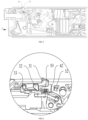
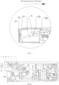
- the plug-in circuit breaker of the present invention comprises the housing 6, the button mechanism, the operating mechanism 9 drivingly connected with the button mechanism, the movable contact 9a connected with the operating mechanism 9, and the stationary contact 9b arranged opposite to the movable contact 9a, moreover, generally includes, but is not limited to, the short-circuit protection mechanism 11, the arc extinguishing apparatus 12, the overload protection mechanism 14, the wire-outlet connecting apparatus 13, the wire-inlet connecting apparatus 1a, 1b and other components of circuit breakers (not shown).
- the button mechanism actuates the operating mechanism 9 to activate the movable contact to in contact with the stationary contact, or actuates the operating mechanism 9 to activate the movable contact to break contact off the stationary contact, and the button mechanism has a closing position and a opening position corresponding to a closing state and a opening state of a circuit breaker.
- a locking apparatus is further arranged inside the plug-in circuit breaker, the limiting hole 61 fitting with the locking apparatus is arranged on the housing 6, and the cabinet limiting hole B0 is formed on the sheet metal part of the receiver which the plug-in circuit breaker inserted thereinto.
- the plug-in circuit breaker of the present invention includes the housing 6 provided with the limiting hole 61, a button mechanism and the operating mechanism 9, wherein the button mechanism actuates the operating mechanism 9 to perform closing and opening operations, and the button mechanism has the closing position and the opening position corresponding to the closing state and the opening state of the circuit breaker.
- the button mechanism includes the button 2, the connecting rod 7 and the driving member 5, wherein the button 2 activates the driving member 5 to act by means of the connecting rod 7, the driving member 5 is rotatably arranged inside the housing 6 and connected with the operating mechanism 9.
- Pressing the button 2 actuates the driving member 5 to rotate towards one side by means of the connecting rod 7, and the driving member 5 actuates the operating mechanism 9 to activate the movable contact 9a and the stationary contact 9b to in contact with each other by means of the U-shaped rod 8.
- Pulling out the button 2 actuates the driving member 5 to rotate towards the other side by means of the connecting rod 7, and the driving member 5 actuates the operating mechanism 9 to activate the movable contact 9a and the stationary contact 9b to break contact with each other by means of the U-shaped rod 8.
- the driving member 5 has a function similar to that of the handles of conventional small circuit breakers, the operating mechanism usually includes a contact support connected with the movable contact 9a, a lock catch and a jump buckle, the short-circuit protection mechanism and the overload protection mechanism are arranged correspondingly to the lock catch of the operating mechanism; when a short-circuit fault or an overload fault occurs, acting on the lock catch enables the operating mechanism to trip off, so that the circuit breaker enters the opening state for protection.
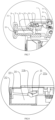
- the linkage member 3 retracts into the housing 6, and the locking protruding stand 41 of the locking member 4 extends out of the limiting hole 61 of the housing 6, applying an external force for retraction on the locking member 4, then the locking member 4 can be pushed back into the housing 6 under the action of the external force for retraction.
- the abutting protruding stand 31 of the linkage member 3 is arranged correspondingly to the second limiting hole on the housing 6, the second limiting hole and the limiting hole 61 are arranged side by side, when the button mechanism is in the closing position, the abutting protruding stand 31 extends out of the second limiting hole of the housing 6.
- the circuit breaker is closed before installation, thus the first driving portion 20 of the button 2 actuates the linkage member to rotate counterclockwise, the abutting protruding stand 31 of the linkage member 3 extends out of the limiting hole 61 of the housing 6, and the first driving portion 20 of the button 2 abuts against and is limited at the extension position, so it cannot retract into the housing, when the circuit breaker is reinstalled in the cabinet body, the right contour surface 31b of the abutting protruding stand 31 abuts against and fits with the transverse end face B1 of the cabinet sheet metal part, the circuit breaker cannot be installed to the operating position, avoiding energized operations, and improving safety.
- the locking member 4 is installed inside the housing 6 by means of an elastic member, the locking member 4 is provided with the locking protruding stand 41 arranged opposite to the limiting hole 61, the elastic member is installed between the locking member 4 and the housing 6.
- the locking member 4 has two operating positions for retraction and extension, the elastic member enables the locking protruding stand 41 of the locking member 4 to extend out of the limiting hole 61.
- an external force for retraction is applied on the locking member 4, and then the locking member 4 retracts the locking protruding stand 41 into the housing against a bias force of the elastic member.
- the locking member 4 may also abut against the button 2 or the connecting rod 7, for example, by limiting the button 2 with the protrusion or slot on the button 2, the button 2 cannot press toward the inside of the circuit breaker to closing, and the connecting rod 7 cannot move toward the closing position by abutting against the hook extending on the connecting rod 7.
- the locking protruding stand 41 of the locking member 4 when the button mechanism is in the closing position, the locking protruding stand 41 of the locking member 4 extends out of the limiting hole 61 of the housing 6 and is limited by the button mechanism at the extension position, so it cannot retract into the housing, furthermore it is used for assisting the linkage member 3, preventing the circuit breaker from being inserted into the cabinet and pulled out from the cabinet in the closing state(the locking member 4 plays an auxiliary role; as there is a certain angle of inclination between the inclined surface 412 of the locking protruding stand 41 of the locking member and the outer surface of the circuit breaker, even if the locking protruding stand 41 is always exposed outside, it is still possible to forcibly push it into the circuit breaker in the closing state, with some elasticity in the structure of the cabinet sheet metal part, thereby causing potential safety hazards).
- the button mechanism can be pulled out to move toward the outside of the housing 6, during such movement, the button mechanism enables the locking protruding stand 41 of the locking member 4 to return into the housing 6.
- the button mechanism actuates the linkage member 3, then the linkage member 3 drives the locking member 4 to unlock, so that the locking protruding stand 41 retracts into the housing 6.
- the locking member 4 is installed inside the housing 6 by means of a linear sliding pair, the direction of the linear movement thereof is perpendicular to the installation-insertion direction of the circuit breaker, and the locking member 4 is arranged between the button mechanism and the limiting hole 61.
- the upper portion of the locking member 4 close to the limiting hole 61 is provided with the locking protruding stand 41, and the lower portion of the locking member 4 close to the button mechanism is provided with the extending post 42.
- the linkage step 43 fitting with the linkage member 3 is arranged on one side of the locking protruding 41, and the elastic member is arranged between the lower portion of the locking member 4 and the housing 6, enabling the locking protruding stand 41 of the locking member 4 to extend out of the limiting hole 61.
- the linkage member 3 is rotatably arranged on the housing 6, and positioned between the button mechanism 2 and the limiting hole 61, and the linkage member 3 includes the abutting protruding stand 31 and the activated protruding stand 32.
- the button mechanism enables the abutting protruding stand 31 to extend out of the limiting hole 61 by pushing the activated protruding stand 32, and the button mechanism abuts against and fits with the activated protruding stand 32 so that the abutting protruding stand 31 cannot retract into the housing 6.
- the button mechanism releases the abutting fit with the activated protruding stand 32 and is displaced, thus the abutting protruding stand 31 retracts into the housing.
- the button mechanism includes the button 2, the connecting rod 7, and the driving member 5, the button 2 actuates the driving member 5 to act by means of the connecting rod 7, the driving member 5 is rotatably arranged in the housing 6 and connected to the operating mechanism 9.
- the button 2 is provided with the first driving portion 20 fitting with the activated protruding stand 32. Pressing the button 2 actuates the operating mechanism to perform the closing operation by the connecting rod 7 and the driving member 5.
- Pulling the button 2 actuates the operating mechanism to perform the pening operation by the connecting rod 7 and the driving member 5, when the button mechanism is in the opening position, the first driving portion 20 of the button 2 is dislocated and displaced with the activated protruding stand 32, so that the abutting protruding stand 31 retracts into the housing.
- the linkage member 3 may be actuated to rotate clockwise by the button mechanism to retract the abutting protruding stand 31 into the housing, of course, the spring may also be configured to rotate it clockwise, or the gravity of one end of the abutting protruding stand 31 may be depended to rotate it clockwise.
- the linkage member 3 has the middle provided with a rotating center, one end provided with the abutting protruding stand 31 at one side close to the limiting hole 61 and provided with the unlocking portion 34 fitting with the locking member 4 at the other side, and the other end provided with the linkage driving portion 33 bending toward the button mechanism, and activated protruding stand 32 is arranged at one side, close to the button mechanism, between the rotating center and the abutting protruding stand 31.
- the button mechanism is provided with the driving portion fitting with the linkage driving portion 33.
- the button mechanism releases the abutting fit with the activated protruding stand 32 and is displaced while moving toward the outside of the housing 6, and the driving portion on the button mechanism pulls the linkage driving portion 33 to actuate the linkage member 3 to rotate, so that the abutting protruding stand 31 retracts into the housing.
- the button mechanism can be pulled to move toward the outside of the housing 6, and the driving portion continues to drive the linkage member 3 to rotate while the button mechanism continues to move toward the outside of the housing 6, so that the unlocking portion 34 applies an external retracting force on the locking member 4, thus the locking member 4 returns to the housing 6.
- the button 2 of the button mechanism includes the button member 21 and the indicating member 22, thus the indicating member 22 fits with the linkage member 3, while achieving an indication of opening and closing, and the locking protruding stand 41 of the locking member 4 can be actuated to retract into the housing 6 after circuit breaker is opened.
- the indicating member 22 includes the rotating shaft 221, the display end surface 223, and the driving protruding stand 222 arranged on the rotating shaft 221. The driving portion fits with the linkage member driving portion 33 of the linkage member 3 by means of the driving protruding stand 222, and the display end surface 223 is provided with an indicating portion used as a opening and closing indicator.
- the indicating portion is provided with a corresponding color block or text serving as a opening and closing indicator, the cavitated installing hole 211 is arranged inside the button member 21, and the operation end face of the button member 21 is provided with the observation window 212 communicating with the installing hole 211.
- the indicating member 22 is installed inside the installing hole 211 of the button member 21 by means of the rotating shaft 22 and swings around the shaft. Such swinging action drives the indicating portion on the display end surface 223 to move under the observation window 212, the corresponding closing and opening state are indicated by moving the indicating portion into the observation window 212.
- the button 2 moves toward inside of the housing 6, and the driving protruding stand 222 fits with the bending end 32, enabling the indicating member 22 to rotate, so that the region of the indicating portion on the display end surface 223 corresponding to the closing state faces the observation window 212.
- the button 2 moves toward the outside of the housing 6, and the driving protruding stand 222 of the indicating member 22 fits with the linkage driving portion 33, thus the indicating member 22 rotates such that the region of the indicating portion on the display end surface 223 corresponding to the opening state faces the observation window 212 corresponding to the opening state.
- the linkage member 3 actuates the linkage member driving portion 33 to rotate, so that the driving protruding stand 222 enables the abutting protruding stand 31 to retract into the housing, and at this time, the unlocking portion 34 of the linkage member 3 has not yet actuated the locking member 4 to retract into the housing 6(the unlocking portion 34 is just in contact with the linkage step 43 of the locking member 4, or leaves a gap).
- the button 2 continues to be pulled, while the button 2 moves toward the outside of the housing 6, the driving protruding stand 222 drives the linkage 3 to rotate by the linkage member driving portion 33, thus the unlocking portion 34 applies a force on the locking member 4 to retract the locking member 4 into the housing 6.
- the driving protruding stand 222 is arranged on one side of the rotating shaft 221, and the driving protruding stand 222 extends out of the button 2 to fit with the linkage member driving portion 33, of course, the linkage member driving portion 33 may reversely bend and extend into the button 2 to fit with the driving protruding stand 222, in addition, the driving protruding stand 222 may not be arranged on the rotating shaft 221, instead on one side of the connecting rod between the rotating shaft 221 and the display end surface 223.
- the left activated end 222b and the right activated end 222a are arranged on the driving protruding stand 222 of the indicating member 22 at intervals, and one side of the linkage member driving portion 33 of the linkage member 3 bending toward the button 2 is positioned between the left activated end 222b and the right activated end 222a, when the button 2 presses toward the interior of the circuit breaker to closing, the inclined surface of the left activated end 222b rotates counterclockwise under the resistance of the linkage member driving portion 33, and at this time, the closing identifier corresponding to the color of the indicating portion on the display end surface 223 can be displayed on the observation window 212.
- This technical solution is simple in structure, and can be combined with to simplify the unlocking structure.
- one side of the activated protruding stand 32 close to the button 2 is an inclined surface.
- the button mechanism includes the button 2, the connecting rod 7 and the driving member 5.
- the button 2 actuates the driving member 5 to rotate by the connecting rod 7, which actuates the operating mechanism 9 to perform the closing/ opening operation by the connecting rod 8.
- the button mechanism and the driving member 5 respectively have the closing position /opening position corresponding to the closing state /opening state of the circuit breaker.
- the button mechanism and the driving member 5 respectively have a determined position (closing position), and in the opening state, the button mechanism and the driving member 5 also respectively have a determined position (opening position); and the closing position/opening position corresponds to the closing state/opening state of the movable contact 9a and the stationary contact 9b.
- the limiting hole 61 is arranged on the housing 6, the locking member 4 is slidably arranged at the position corresponding to the driving member 5 and positioned between the driving member 5 and the limiting hole 61, the linkage member 3 is rotatably arranged between the button 2 and the limiting hole 61, the linkage member 3 is arranged on the left side of the locking member 4 and positioned above the button mechanism.
- the present invention has a beneficial feature in that when the button mechanism is in the closing position, the linkage member 3 is limited in the extension position by the button mechanism and cannot retract into the retraction position.
- the structure has the beneficial effects in that: reliable prevention from plug-in and plug-out operations in the closing state, that is, preventing the circuit breaker from being forcibly inserted and pulled out in the closing state; and effective capability to enhance for circuit breaker products against non-normal forcible plug-in and plug-out operations with the characteristic of the incapability provided by this structure to retract in to the retraction position.
- the button mechanism When the button mechanism is in the opening position, there may be a plurality of technical solutions in the position where the linkage member 3 is positioned.
- the linkage member 3 is not limited by the button mechanism and can be converted between the extension position and the retraction position, so it has its advantage in a simple structure.
- the linkage member 3 is limited by the button mechanism and is in the retraction position when the button mechanism is in the opening position, so it has its advantage in direct avoidance of the resistance of the linkage member 3 to normal plug-in and plug-out operations of the circuit breaker.
- the present invention has another advantage in that the linkage member 3 acts as an unlocking member, so as to simplify the structure of the unlocking mechanism, and cut down the number of parts, and can enable the linkage member 3 and the driving locking member 4 to retract at the same time, so that the linkage member 3 and the driving locking member 4 do not generate any resistance to normal plug-in and plug-out operations of the circuit breaker.
- the present invention has another beneficial feature in that the locking protruding stand 41 of the locking member 4 extends out of the housing 6 when the circuit breaker is in the opening state, but under an external force for retraction it can retract into the housing 6 by the force (only with a horizontal force, the locking member 4 will not retract, and it is necessary for a vertical component force to exist in the retraction direction), that is, the circuit breaker is not prevented from being inserted into the cabinet in the opening state, and the circuit breaker can be protected from falling out of the cabinet with vibration during a transportation process.
- the locking member 4 of the present invention has the beneficial effects as follows:
Landscapes
- Switch Cases, Indication, And Locking (AREA)
- Breakers (AREA)
Claims (14)
- Steckbarer Trennschalter, umfassend ein Gehäuse (6), einen Betriebsmechanismus (9) und einen Knopfmechanismus, wobei der Knopfmechanismus den Betriebsmechanismus (9) betätigt, um den Öffnungs-/Schließvorgang durchzuführen, und eine Schließstellung und eine Öffnungsstellung aufweist, die Schließ-/Öffnungszuständen des Trennschalters entsprechen, worin der Trennschalter ferner ein Sperrglied (4) und ein Gestängeglied (3) umfasst, die innerhalb des Gehäuses (6) angeordnet sind, wobei das Gestängeglied (3) mit einer anliegenden vorstehenden Stütze (31) versehen ist, wobei das Sperrglied (4) mit einer sperrenden vorstehenden Stütze (41) versehen ist;so dass, wenn der Knopfmechanismus sich in der Schließstellung befindet, die anliegende vorstehende Stütze (31) des Gestängeglieds (3) sich aus dem Gehäuse (6) heraus erstreckt und vom Knopfmechanismus (2) an einer Auszugsstellung begrenzt wird, so dass sie sich in das Gehäuse nicht zurückziehen kann;dadurch gekennzeichnet, dass, wenn der Knopfmechanismus sich in der Öffnungsstellung befindet, das Gestängeglied (3) sich in das Gehäuse (6) zurückzieht, die sperrende vorstehende Stütze (41) des Sperrgliedes (4) sich aus dem Gehäuse (6) heraus erstreckt, und die sperrende vorstehende Stütze (41) des Sperrgliedes (4) in das Gehäuse (6) unter der Wirkung einer äußeren Kraft zum Einzug zurückgeschoben werden kann,worin, wenn der Knopfmechanismus sich in der Öffnungsstellung befindet, die sperrende vorstehende Stütze (41) des Sperrgliedes (4) sich in das Gehäuse (6) unter der Wirkung der äußeren Kraft zum Einzug zurückzieht, wodurch das Sperrglied (4) an den Knopfmechanismus anliegt und dazu passt, um den Knopfmechanismus daran zu hindern, von der Öffnungsstellung zur Schließstellung umzuschalten.
- Steckbarer Trennschalter nach Anspruch 1, worin, wenn der Knopfmechanismus sich in der Schließstellung befindet, die sperrende vorstehende Stütze (41) des Sperrgliedes (4) sich aus dem Gehäuse heraus erstreckt und vom Knopfmechanismus an der Auszugsstellung begrenzt wird, so dass sie sich in das Gehäuse nicht zurückziehen kann.
- Steckbarer Trennschalter nach Anspruch 1, worin, nachdem der Trennschalter geöffnet ist, der Knopfmechanismus herausgezogen werden kann, um sich zum Äußeren des Gehäuses (6) hin zu bewegen; während dieser Bewegung der Knopfmechanismus der sperrenden vorstehenden Stütze (41) des Sperrgliedes (4) ermöglicht, in das Gehäuse (6) zurückzukehren.
- Steckbarer Trennschalter nach Anspruch 3, worin während der Bewegung des Knopfmechanismus zum Äußeren des Gehäuses (6) hin, der Knopfmechanismus das Gestängeglied (3) betätigt, das Gestängeglied (3) das Sperrglied (4) zum Lösen antreibt, so dass die sperrende vorstehende Stütze (41) sich in das Gehäuse (6) zurückzieht.
- Steckbarer Trennschalter nach Anspruch 4, worin das Gestängeglied (3) an dem Gehäuse (6) drehbar angeordnet ist, und einen Entsperrabschnitt (34), der zum Sperrglied (4) passt, und einen Gestängeantriebsabschnitt (33), der zum Knopfmechanismus passt, umfasst, wobei der Knopfmechanismus, während der Bewegung zum Äußeren des Gehäuses (6) hin, das Gestängeglied (3), mittels des Gestängeantriebsabschnitts (33), zum Drehen antreibt, der Entsperrabschnitt (34) eine Kraft auf das Sperrglied (4) anwendet, um die sperrende vorstehende Stütze (41) des Sperrgliedes (4) in das Gehäuse (6) einzuziehen.
- Steckbarer Trennschalter nach Anspruch 1, worin der Knopfmechanismus einen Knopf (2), einen Verbindungsstab (7) und ein Antriebsglied (5) umfasst, der Knopf (2) das Antriebsglied (5) antreibt, um mittels des Verbindungsstabs (7) zu wirken, das Antriebsglied (5) innerhalb des Gehäuses (6) drehbar angeordnet ist und mit dem Betriebsmechanismus (9) verbunden ist.
- Steckbarer Trennschalter nach Anspruch 6, worin, wenn der Knopfmechanismus sich in der Schließstellung befindet, die sperrende vorstehende Stütze (41) des Sperrgliedes (4) sich aus dem Gehäuse (6) heraus erstreckt, und die äußere Seitenfläche (52) des Antriebsglieds (5) an das Sperrglied (4) anliegt und dazu passt, so dass das Sperrglied (4) sich in das Gehäuse (6) nicht zurückziehen kann; wenn der Knopfmechanismus sich in der Öffnungsstellung befindet, die äußere Seitenfläche (52) des Antriebsglieds (5) zum Sperrglied (4) fehlausgerichtet ist, um die Anlagepassung zu lösen.
- Steckbarer Trennschalter nach Anspruch 6, worin das Sperrglied (4) ferner einen Ausziehpfosten (42) umfasst, das Antriebsglied (5) ferner einen Antriebsbegrenzungsabschnitt (51) umfasst, der zum Ausziehpfosten (42) passt, wenn der Knopfmechanismus sich in der Öffnungsstellung befindet, der Antriebsbegrenzungsabschnitt (51) des Antriebsglieds (5) dem Ausziehpfosten (42) des Sperrglieds (4) gegenüberliegt, wenn die sperrende vorstehende Stütze (41) des Sperrglieds (4) sich in das Gehäuse zurückzieht, der Ausziehpfosten (42) des Sperrglieds (4) in Begrenzungspassung zum Antriebsbegrenzungsabschnitt (51) steht, um das Antriebsglied (5) daran zu hindern, sich in die Schließrichtung zu drehen, wodurch es verhindert wird, dass der Knopfmechanismus von der Öffnungsstellung zur Schließstellung umschaltet.
- Steckbarer Trennschalter nach Anspruch 1, worin das Sperrglied (4) innerhalb des Gehäuses (6) mittels eines elastischen Gliedes installiert ist, das elastische Glied zwischen dem Sperrglied (4) und dem Gehäuse (6) installiert ist, das elastische Glied der sperrenden vorstehenden Stütze (41) des Sperrglieds (4) ermöglicht, sich aus dem Gehäuse heraus zu erstrecken.
- Steckbarer Trennschalter nach Anspruch 1, worin das Gestängeglied (3) die anliegende vorstehende Stütze (31) und eine betätigte vorstehende Stütze (32) umfasst, während des Schließvorgangs der Knopfmechanismus der anliegenden vorstehenden Stütze (31) ermöglicht, sich aus dem Gehäuse heraus zu erstrecken, indem die betätigte vorstehende Stütze (32) gedrückt wird, und der Knopfmechanismus an die betätigte vorstehende Stütze (32) anliegt und dazu passt, so dass die anliegende vorstehende Stütze (31) sich in das Gehäuse (6) nicht zurückziehen kann, während des Öffnungsvorgangs der Knopfmechanismus die Anlagepassung zur betätigten vorstehenden Stütze (32) löst und verschoben wird, so dass die anliegende vorstehende Stütze (31) sich in das Gehäuse zurückzieht.
- Steckbarer Trennschalter nach Anspruch 1, worin ein Begrenzungsloch (61) an dem Gehäuse (6) angeordnet ist, die anliegende vorstehende Stütze (31) des Gestängeglieds (3) und die sperrende vorstehende Stütze (41) des Sperrglieds (4) zum identischen Begrenzungsloch (61) passen.
- Steckbarer Trennschalter nach Anspruch 10, worin der Knopfmechanismus einen Knopf (2), einen Verbindungsstab (7) und ein Antriebsglied (5) umfasst, der Knopf (2) das Antriebsglied (5) antreibt, um mittels des Verbindungsstabs (7) zu wirken, das Antriebsglied (5) innerhalb des Gehäuses (6) drehbar angeordnet ist und mit dem Betriebsmechanismus (9) verbunden ist, der Knopf (2) mit einem ersten Antriebsabschnitt (20) versehen ist, der zur betätigten vorstehenden Stütze (32) passt, wenn der Knopfmechanismus sich in der Schließstellung befindet, der Knopf (2) und die betätigte vorstehende Stütze (32) an den ersten Antriebsabschnitt (20) anliegen, wenn der Knopfmechanismus sich in der Öffnungsstellung befindet, der erste Antriebsabschnitt (20) des Knopfes (2) mit der betätigten vorstehenden Stütze (32) versetzt und verschoben wird.
- Steckbarer Trennschalter nach Anspruch 1, worin ein Begrenzungsloch (61), das zur sperrenden vorstehenden Stütze (41) passt, am Gehäuse (6) angeordnet ist, das Sperrglied (4) innerhalb des Gehäuses (6) mittels eines linearen Gleitpaares installiert ist, die Richtung der linearen Bewegung davon zur Installations-Einführungsrichtung des Trennschalters senkrecht ist, das Sperrglied (4) zwischen dem Knopfmechanismus und dem Begrenzungsloch (61) angeordnet ist, der obere Abschnitt des Sperrglieds (4), der dem Begrenzungsloch (61) nahe ist, mit der sperrenden vorstehenden Stütze (41) versehen ist, und der untere Abschnitt des Sperrglieds (4), der dem Knopfmechanismus nahe ist, mit einem Ausziehpfosten (42) versehen ist, eine Gestängestufe (43), die zum Gestängeglied (3) passt, an einer Seite der sperrenden vorstehenden Stütze (41) angeordnet ist.
- Steckbarer Trennschalter nach Anspruch 10, worin das Gestängeglied (3) seine Mitte, die mit einem Drehmittelpunkt versehen ist, ein Ende, das mit der anliegenden vorstehenden Stütze (31) an einer Seite und mit einem Entsperrabschnitt (34), das zum Sperrglied (4) passt, an der anderen Seite versehen ist, und das andere Ende, das mit einem Gestängeantriebsabschnitt (33) versehen ist, aufweist, die betätigte vorstehende Stütze (32) an einer Seite, die dem Knopfmechanismus nahe ist, zwischen dem Drehmittelpunkt und der anliegenden vorstehenden Stütze (31) angeordnet ist, der Knopfmechanismus mit dem Antriebsabschnitt versehen ist, das zum Gestängeantriebsabschnitt (33) passt, während des Öffnungsvorgangs der Knopfmechanismus die Anlagepassung zur betätigten vorstehenden Stütze (32) löst und verschoben wird, während er sich zum Äußeren des Gehäuses (6) hin bewegt, und der Antriebsabschnitt am Knopfmechanismus den Gestängeantriebsabschnitt (33) zieht, damit er das Gestängeglied (3) zum Drehen antreibt, so dass die anliegende vorstehende Stütze (31) sich in das Gehäuse zurückzieht; wenn der Knopfmechanismus sich in der Öffnungsstellung befindet, der Knopfmechanismus gezogen werden kann, um sich zum Äußeren des Gehäuses (6) hin zu bewegen, und der Antriebsabschnitt das Gestängeglied (3) zum Drehen weiter antreibt, während der Knopfmechanismus sich zum Äußeren des Gehäuses (6) hin weiter bewegt, so dass der Entsperrabschnitt (34) eine äußere Einzugskraft auf das Sperrglied (4) anwendet, wodurch das Sperrglied (4) zum Gehäuse (6) zurückkehrt.
Applications Claiming Priority (2)
| Application Number | Priority Date | Filing Date | Title |
|---|---|---|---|
| CN201911122584.9A CN111477513B (zh) | 2019-11-15 | 2019-11-15 | 插入式断路器 |
| PCT/CN2020/128877 WO2021093878A1 (zh) | 2019-11-15 | 2020-11-14 | 插入式断路器 |
Publications (4)
| Publication Number | Publication Date |
|---|---|
| EP4060709A1 EP4060709A1 (de) | 2022-09-21 |
| EP4060709A4 EP4060709A4 (de) | 2023-11-22 |
| EP4060709B1 true EP4060709B1 (de) | 2025-04-09 |
| EP4060709C0 EP4060709C0 (de) | 2025-04-09 |
Family
ID=71744949
Family Applications (1)
| Application Number | Title | Priority Date | Filing Date |
|---|---|---|---|
| EP20887460.2A Active EP4060709B1 (de) | 2019-11-15 | 2020-11-14 | Steckbarer trennschalter |
Country Status (7)
| Country | Link |
|---|---|
| US (1) | US12159764B2 (de) |
| EP (1) | EP4060709B1 (de) |
| JP (1) | JP7659555B2 (de) |
| CN (1) | CN111477513B (de) |
| AU (1) | AU2020384683B2 (de) |
| BR (1) | BR112022009368A2 (de) |
| WO (1) | WO2021093878A1 (de) |
Families Citing this family (10)
| Publication number | Priority date | Publication date | Assignee | Title |
|---|---|---|---|---|
| CN111477513B (zh) * | 2019-11-15 | 2025-07-15 | 浙江正泰电器股份有限公司 | 插入式断路器 |
| CN111477509B (zh) * | 2020-04-13 | 2025-09-02 | 浙江正泰电器股份有限公司 | 断路器 |
| CN111968867A (zh) * | 2020-08-07 | 2020-11-20 | 上海瑞忒尔电气技术有限公司 | 一种开关装置的固定扣结构 |
| CN111900045B (zh) * | 2020-08-31 | 2025-04-22 | 环宇高科有限公司 | 一种断路器的锁定和解锁装置 |
| CN111900046B (zh) * | 2020-08-31 | 2025-05-16 | 环宇高科有限公司 | 一种断路器的固定和解锁装置 |
| CN112271121B (zh) * | 2020-10-31 | 2026-01-20 | 中韶电气股份有限公司 | 近方形断路器的安装锁定与拆装解锁机构 |
| CN115547714B (zh) * | 2021-06-29 | 2026-02-27 | 上海良信电器股份有限公司 | 一种锁定机构及断路器 |
| CN114220712B (zh) * | 2021-12-30 | 2024-10-29 | 常熟开关制造有限公司(原常熟开关厂) | 一种断路器的操作机构 |
| CN115513013A (zh) * | 2022-08-26 | 2022-12-23 | 华为数字能源技术有限公司 | 断路器、供电装置及配电设备 |
| CN118335570B (zh) * | 2024-05-17 | 2025-06-20 | 浙江德菱科技股份有限公司 | 一种结构紧凑的智能型断路器 |
Family Cites Families (12)
| Publication number | Priority date | Publication date | Assignee | Title |
|---|---|---|---|---|
| JP5231834B2 (ja) * | 2008-02-21 | 2013-07-10 | パナソニックエコソリューションズ電路株式会社 | 回路遮断器 |
| CN204029738U (zh) * | 2014-06-23 | 2014-12-17 | 佳一电气有限公司 | 断路器手电动一体操作机构 |
| CN207624637U (zh) * | 2017-10-26 | 2018-07-17 | 上海良信电器股份有限公司 | 一种插入式小型断路器 |
| CN107833799B (zh) * | 2017-10-26 | 2024-09-20 | 上海良信电器股份有限公司 | 一种插入式断路器的固定及解锁机构 |
| CN209487449U (zh) * | 2018-12-28 | 2019-10-11 | 浙江正泰电器股份有限公司 | 小型断路器 |
| CN209544266U (zh) * | 2018-12-28 | 2019-10-25 | 浙江正泰电器股份有限公司 | 小型断路器 |
| CN109686626B (zh) * | 2018-12-28 | 2024-05-07 | 浙江正泰电器股份有限公司 | 小型断路器 |
| CN109637907B (zh) * | 2018-12-28 | 2024-05-14 | 浙江正泰电器股份有限公司 | 小型断路器 |
| CN109585233B (zh) * | 2018-12-28 | 2024-05-14 | 浙江正泰电器股份有限公司 | 小型断路器 |
| CN110400727B (zh) * | 2019-08-01 | 2025-02-25 | 浙江正泰电器股份有限公司 | 断路器 |
| CN211350528U (zh) * | 2019-11-15 | 2020-08-25 | 浙江正泰电器股份有限公司 | 插入式断路器 |
| CN111477513B (zh) * | 2019-11-15 | 2025-07-15 | 浙江正泰电器股份有限公司 | 插入式断路器 |
-
2019
- 2019-11-15 CN CN201911122584.9A patent/CN111477513B/zh active Active
-
2020
- 2020-11-14 EP EP20887460.2A patent/EP4060709B1/de active Active
- 2020-11-14 AU AU2020384683A patent/AU2020384683B2/en active Active
- 2020-11-14 JP JP2022527238A patent/JP7659555B2/ja active Active
- 2020-11-14 BR BR112022009368A patent/BR112022009368A2/pt unknown
- 2020-11-14 WO PCT/CN2020/128877 patent/WO2021093878A1/zh not_active Ceased
- 2020-11-14 US US17/776,289 patent/US12159764B2/en active Active
Also Published As
| Publication number | Publication date |
|---|---|
| AU2020384683A1 (en) | 2022-05-26 |
| US20230012081A1 (en) | 2023-01-12 |
| JP7659555B2 (ja) | 2025-04-09 |
| BR112022009368A2 (pt) | 2022-08-09 |
| EP4060709A4 (de) | 2023-11-22 |
| CN111477513A (zh) | 2020-07-31 |
| WO2021093878A1 (zh) | 2021-05-20 |
| US12159764B2 (en) | 2024-12-03 |
| JP2023502907A (ja) | 2023-01-26 |
| EP4060709C0 (de) | 2025-04-09 |
| AU2020384683B2 (en) | 2023-11-30 |
| CN111477513B (zh) | 2025-07-15 |
| EP4060709A1 (de) | 2022-09-21 |
Similar Documents
| Publication | Publication Date | Title |
|---|---|---|
| EP4060709B1 (de) | Steckbarer trennschalter | |
| CN109686626B (zh) | 小型断路器 | |
| CN109585233B (zh) | 小型断路器 | |
| CN109686625B (zh) | 小型断路器 | |
| CN109599303B (zh) | 小型断路器 | |
| US11972919B2 (en) | Plug-in circuit breaker | |
| CN109786186B (zh) | 小型断路器 | |
| CN111477511B (zh) | 插入式断路器 | |
| AU2019412346B2 (en) | Miniature circuit breaker | |
| CN109727826B (zh) | 小型断路器 | |
| CN211238115U (zh) | 插入式断路器 | |
| EP4060711B1 (de) | Steckbarer trennschalter | |
| CN111489924B (zh) | 插入式断路器 | |
| CN211350528U (zh) | 插入式断路器 | |
| CN112820595A (zh) | 能防止合闸插拔的双锁头插入式断路器 | |
| CN211208370U (zh) | 断路器 | |
| CN110828245B (zh) | 一种插入式断路器的连接机构 | |
| CN111489925B (zh) | 插入式断路器 | |
| CN111477506B (zh) | 断路器外壳及插入式断路器 | |
| CN220155455U (zh) | 断路器的漏电保护模块 | |
| CN222734916U (zh) | 报警辅助触头及断路装置 | |
| CN216054533U (zh) | 断路器 | |
| CN116581003A (zh) | 一种断路器上的动触头操作机构 | |
| CN115966420A (zh) | 用于开关柜的锁定装置和开关柜 | |
| CN120809549A (zh) | 塑壳断路器 |
Legal Events
| Date | Code | Title | Description |
|---|---|---|---|
| STAA | Information on the status of an ep patent application or granted ep patent |
Free format text: STATUS: THE INTERNATIONAL PUBLICATION HAS BEEN MADE |
|
| PUAI | Public reference made under article 153(3) epc to a published international application that has entered the european phase |
Free format text: ORIGINAL CODE: 0009012 |
|
| STAA | Information on the status of an ep patent application or granted ep patent |
Free format text: STATUS: REQUEST FOR EXAMINATION WAS MADE |
|
| 17P | Request for examination filed |
Effective date: 20220510 |
|
| AK | Designated contracting states |
Kind code of ref document: A1 Designated state(s): AL AT BE BG CH CY CZ DE DK EE ES FI FR GB GR HR HU IE IS IT LI LT LU LV MC MK MT NL NO PL PT RO RS SE SI SK SM TR |
|
| DAV | Request for validation of the european patent (deleted) | ||
| DAX | Request for extension of the european patent (deleted) | ||
| A4 | Supplementary search report drawn up and despatched |
Effective date: 20231019 |
|
| RIC1 | Information provided on ipc code assigned before grant |
Ipc: H01H 71/10 20060101AFI20231013BHEP |
|
| GRAP | Despatch of communication of intention to grant a patent |
Free format text: ORIGINAL CODE: EPIDOSNIGR1 |
|
| STAA | Information on the status of an ep patent application or granted ep patent |
Free format text: STATUS: GRANT OF PATENT IS INTENDED |
|
| INTG | Intention to grant announced |
Effective date: 20241031 |
|
| GRAS | Grant fee paid |
Free format text: ORIGINAL CODE: EPIDOSNIGR3 |
|
| GRAA | (expected) grant |
Free format text: ORIGINAL CODE: 0009210 |
|
| STAA | Information on the status of an ep patent application or granted ep patent |
Free format text: STATUS: THE PATENT HAS BEEN GRANTED |
|
| AK | Designated contracting states |
Kind code of ref document: B1 Designated state(s): AL AT BE BG CH CY CZ DE DK EE ES FI FR GB GR HR HU IE IS IT LI LT LU LV MC MK MT NL NO PL PT RO RS SE SI SK SM TR |
|
| REG | Reference to a national code |
Ref country code: GB Ref legal event code: FG4D |
|
| REG | Reference to a national code |
Ref country code: CH Ref legal event code: EP |
|
| REG | Reference to a national code |
Ref country code: DE Ref legal event code: R096 Ref document number: 602020049312 Country of ref document: DE |
|
| REG | Reference to a national code |
Ref country code: IE Ref legal event code: FG4D |
|
| U01 | Request for unitary effect filed |
Effective date: 20250508 |
|
| U07 | Unitary effect registered |
Designated state(s): AT BE BG DE DK EE FI FR IT LT LU LV MT NL PT RO SE SI Effective date: 20250515 |
|
| PG25 | Lapsed in a contracting state [announced via postgrant information from national office to epo] |
Ref country code: ES Free format text: LAPSE BECAUSE OF FAILURE TO SUBMIT A TRANSLATION OF THE DESCRIPTION OR TO PAY THE FEE WITHIN THE PRESCRIBED TIME-LIMIT Effective date: 20250409 |
|
| PG25 | Lapsed in a contracting state [announced via postgrant information from national office to epo] |
Ref country code: NO Free format text: LAPSE BECAUSE OF FAILURE TO SUBMIT A TRANSLATION OF THE DESCRIPTION OR TO PAY THE FEE WITHIN THE PRESCRIBED TIME-LIMIT Effective date: 20250709 Ref country code: GR Free format text: LAPSE BECAUSE OF FAILURE TO SUBMIT A TRANSLATION OF THE DESCRIPTION OR TO PAY THE FEE WITHIN THE PRESCRIBED TIME-LIMIT Effective date: 20250710 |
|
| PG25 | Lapsed in a contracting state [announced via postgrant information from national office to epo] |
Ref country code: PL Free format text: LAPSE BECAUSE OF FAILURE TO SUBMIT A TRANSLATION OF THE DESCRIPTION OR TO PAY THE FEE WITHIN THE PRESCRIBED TIME-LIMIT Effective date: 20250409 |
|
| PG25 | Lapsed in a contracting state [announced via postgrant information from national office to epo] |
Ref country code: HR Free format text: LAPSE BECAUSE OF FAILURE TO SUBMIT A TRANSLATION OF THE DESCRIPTION OR TO PAY THE FEE WITHIN THE PRESCRIBED TIME-LIMIT Effective date: 20250409 |
|
| PG25 | Lapsed in a contracting state [announced via postgrant information from national office to epo] |
Ref country code: RS Free format text: LAPSE BECAUSE OF FAILURE TO SUBMIT A TRANSLATION OF THE DESCRIPTION OR TO PAY THE FEE WITHIN THE PRESCRIBED TIME-LIMIT Effective date: 20250709 |
|
| PG25 | Lapsed in a contracting state [announced via postgrant information from national office to epo] |
Ref country code: IS Free format text: LAPSE BECAUSE OF FAILURE TO SUBMIT A TRANSLATION OF THE DESCRIPTION OR TO PAY THE FEE WITHIN THE PRESCRIBED TIME-LIMIT Effective date: 20250809 |
|
| U20 | Renewal fee for the european patent with unitary effect paid |
Year of fee payment: 6 Effective date: 20251027 |
|
| PG25 | Lapsed in a contracting state [announced via postgrant information from national office to epo] |
Ref country code: SM Free format text: LAPSE BECAUSE OF FAILURE TO SUBMIT A TRANSLATION OF THE DESCRIPTION OR TO PAY THE FEE WITHIN THE PRESCRIBED TIME-LIMIT Effective date: 20250409 |
|
| PG25 | Lapsed in a contracting state [announced via postgrant information from national office to epo] |
Ref country code: CZ Free format text: LAPSE BECAUSE OF FAILURE TO SUBMIT A TRANSLATION OF THE DESCRIPTION OR TO PAY THE FEE WITHIN THE PRESCRIBED TIME-LIMIT Effective date: 20250409 |
|
| PG25 | Lapsed in a contracting state [announced via postgrant information from national office to epo] |
Ref country code: SK Free format text: LAPSE BECAUSE OF FAILURE TO SUBMIT A TRANSLATION OF THE DESCRIPTION OR TO PAY THE FEE WITHIN THE PRESCRIBED TIME-LIMIT Effective date: 20250409 |
|
| PLBE | No opposition filed within time limit |
Free format text: ORIGINAL CODE: 0009261 |
|
| STAA | Information on the status of an ep patent application or granted ep patent |
Free format text: STATUS: NO OPPOSITION FILED WITHIN TIME LIMIT |
|
| REG | Reference to a national code |
Ref country code: CH Ref legal event code: L10 Free format text: ST27 STATUS EVENT CODE: U-0-0-L10-L00 (AS PROVIDED BY THE NATIONAL OFFICE) Effective date: 20260218 |
|
| 26N | No opposition filed |
Effective date: 20260112 |