EP4060356B1 - Vorrichtung und verfahren zur inspektion eines relais sowie eine ladesäule - Google Patents
Vorrichtung und verfahren zur inspektion eines relais sowie eine ladesäule Download PDFInfo
- Publication number
- EP4060356B1 EP4060356B1 EP22159648.9A EP22159648A EP4060356B1 EP 4060356 B1 EP4060356 B1 EP 4060356B1 EP 22159648 A EP22159648 A EP 22159648A EP 4060356 B1 EP4060356 B1 EP 4060356B1
- Authority
- EP
- European Patent Office
- Prior art keywords
- signal
- detection
- unidirectional conduction
- conduction unit
- relay
- Prior art date
- Legal status (The legal status is an assumption and is not a legal conclusion. Google has not performed a legal analysis and makes no representation as to the accuracy of the status listed.)
- Active
Links
Images


Classifications
-
- G—PHYSICS
- G01—MEASURING; TESTING
- G01R—MEASURING ELECTRIC VARIABLES; MEASURING MAGNETIC VARIABLES
- G01R31/00—Arrangements for testing electric properties; Arrangements for locating electric faults; Arrangements for electrical testing characterised by what is being tested not provided for elsewhere
- G01R31/327—Testing of circuit interrupters, switches or circuit-breakers
- G01R31/3277—Testing of circuit interrupters, switches or circuit-breakers of low voltage devices, e.g. domestic or industrial devices, such as motor protections, relays, rotation switches
- G01R31/3278—Testing of circuit interrupters, switches or circuit-breakers of low voltage devices, e.g. domestic or industrial devices, such as motor protections, relays, rotation switches of relays, solenoids or reed switches
-
- G—PHYSICS
- G01—MEASURING; TESTING
- G01R—MEASURING ELECTRIC VARIABLES; MEASURING MAGNETIC VARIABLES
- G01R1/00—Details of instruments or arrangements of the types included in groups G01R5/00 - G01R13/00 and G01R31/00
- G01R1/02—General constructional details
- G01R1/04—Housings; Supporting members; Arrangements of terminals
- G01R1/0408—Test fixtures or contact fields; Connectors or connecting adaptors; Test clips; Test sockets
- G01R1/0416—Connectors, terminals
Definitions
- Embodiments of the present disclosure relates to charging technologies, and in particular to a detection device for a relay and a method for inspecting a relay, and a charging pile.
- An alternating current relay in an alternating current charging pile that is charging an electric vehicle may be stuck, resulting in a risk of electric shock or charging being out of control.
- adhesion detection on a relay depends on cooperation between two relays, and one of the two relays is always on, failing to perform adhesion detection on two relays simultaneously.
- the relay not stuck has to be turned on in order to detect whether the other relay is stuck following this software logic, which may result in secondary hazards.
- CN106740200A discloses a detection circuit for determining whether a relay is stuck.
- the detection circuit includes a rectification module, an optocoupler, a diode, a pull-up resistor, a current limiting module and a control module.
- CN110901449A discloses a relay detection device for an AC charging pile.
- the relay detection device includes a relay detection module, a detection control switch, an optocoupler isolation output module, and a main control chip.
- a device detection for a relay according to claims 1 or 8, a method for inspecting a relay according to claim 10, and a charging pile according to claim 14 are provided according to the present disclosure, so as to perform adhesion detection on each of all relays in the charging pile without an action of a relay.
- a detection device for a relay includes a detection module and an isolation output module.
- the detection module includes a first signal input terminal and a second signal input terminal. The number of the first signal input terminal is at least one.
- the first signal input terminal is configured to connect to an output side of a to-be-detected relay.
- the second signal input terminal is configured to connect to a neutral wire.
- a signal output terminal of the detection module is configured to connect to a control end of the isolation output module.
- the detection module is configured to output a control signal based on an on-off state of the to-be-detected relay.
- a signal output terminal of the isolation output module is configured to connect to a fault identification device, and the isolation output module is configured to output a detection signal with a duty cycle corresponding to the control signal, to inform the fault identification device to detect whether the to-be-detected relay is stuck.
- the detection module further includes a third unidirectional conduction unit and a fourth unidirectional conduction unit.
- An anode of the third unidirectional conduction unit is connected to an anode of the second unidirectional conduction unit, and the common anode of the third unidirectional conduction unit and the second unidirectional conduction unit serves as a signal output terminal of the detection module.
- a cathode of the fourth unidirectional conduction unit is connected to a cathode of the first unidirectional conduction unit, and the common cathode of the fourth unidirectional conduction unit and the first unidirectional conduction unit serves as another signal output terminal of the detection module.
- a detection device for a relay is further provided according to a second aspect of the present disclosure.
- the detection device includes a detection module and an isolation output module.
- the detection module includes two first signal input terminals, one second signal input terminal, one third signal input terminal and one fourth signal input terminal.
- the two first signal input terminals are configured to respectively connect to output sides of two to-be-detected relays.
- the third signal input terminal is configured to connect to an input side of one of the two to-be-detected relays.
- the second signal input terminal and the fourth signal input terminal are configured to respectively connect to an input side and an output side of another to-be-detected relay.
- a signal output terminal of the detection module is connected to a control end of the isolation output module, and the detection module is configured to output a control signal based on an on-off state of a to-be-detected relay.
- a signal output terminal of the isolation output module is configured to connect to a fault identification device.
- the isolation output module is configured to output a detection signal with a duty cycle corresponding to the control signal, to inform the fault identification device to detect whether there is a to-be-detected relay being stuck.
- the detection device further includes a controllable switch.
- the controllable switch is connected between a signal output terminal of the detection module and the control end of the isolation output module, and a control terminal of the controllable switch is configured to connect to the fault identification device.
- the controllable switch is configured to control, in response to the fault identification device, the detection device to start or stop adhesion detection.
- the detection module includes two first unidirectional conduction units, one second unidirectional conduction unit, one third unidirectional conduction unit and one fourth unidirectional conduction unit.
- First terminals of the first unidirectional conduction units serve as the two first signal input terminals respectively
- second terminals of the two first unidirectional conduction units are connected to a second terminal of the fourth unidirectional conduction unit, as a signal output terminal of the detection module.
- a first terminal of the second unidirectional conduction unit is connected to a first terminal of the third unidirectional conduction unit, as another signal output terminal of the detection module; and a second terminal of the second unidirectional conduction unit serves as the second signal input terminal, and a second terminal of the third unidirectional conduction unit serves as the third signal input terminal.
- Respective first terminals of the four unidirectional conduction units are identical in polarity.
- a method for inspecting a relay is further provided according to a third aspect of the present disclosure.
- the method is applied to the detection device for a relay according to the present disclosure.
- the method includes: outputting, by a detection module, a control signal based on an on-off state of a to-be-detected relay; and outputting, by the isolation output module, a detection signal with a duty cycle corresponding to the control signal, to inform the fault identification device to detect whether the to-be-detected relay is stuck.
- a charging pile is further provided according to the present disclosure.
- the charging pile includes the detection device for a relay according to any one of embodiments of the present disclosure.
- the detection device for a relay includes a detection module.
- the detection module output a control signal to the isolation output module based on an on-off state of the to-be-detected relay.
- the isolation output module outputs a detection signal with a duty cycle to a fault identification device based on the control signal, to inform the fault identification device to detect based on the duty cycle of the detection signal whether the to-be-detected relay is stuck.
- the detection device according to the embodiment can perform adhesion detection on a relay without an action of a relay, having a simple circuit structure.
- the detection device can automatically outputs a detection signal with a duty cycle corresponding to a result of the adhesion detection, so that the fault identification device can automatically detect whether the to-be-detected relay is stuck. It is unnecessary to control a relay to be switched off, and therefore secondary hazards are avoided, thereby improving the safety of the alternating current charging pile.
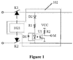
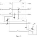
- FIG. 2 is a structural block diagram showing a detection device for a relay according to an embodiment of the present disclosure.
- the device may be arranged in a power supply control device of an alternating current charging pile, so as to perform adhesion detection on a relay in a power supply device of the alternating current charging pile.
- the detection device is especially applicable to an alternating current charging pile including a relay on a live wire only.
- the alternating current charging pile includes a live wire relay.
- a three-phase alternating current charging pile may include three live wire relays K1, K2 and K3, and a single-phase alternating current charging pile may include one live wire relay K3.
- the detection device includes a detection module 100 and an isolation output module 200.
- the detection module 100 includes a first signal input terminal Vin1 and a second signal input terminal Vin2, and the number of the first signal input terminal Vin1 is at least one.
- the first signal input terminal Vin1 is configured to connect to an output side of a to-be-detected relay.
- the second signal input terminal Vin2 is configured to connect to a neutral wire.
- a signal output terminal of the detection module 100 is connected to a control terminal of the isolation output module 200.
- the detection module 100 is configured to output a control signal based on an on-off state of the to-be-detected relay.
- a signal output terminal of the isolation output module 200 is configured to connect to a fault identification device.
- the isolation output module 200 is configured to output a detection signal with a duty cycle corresponding to the control signal, to inform the fault identification device to detect whether the to-be-detected relay is stuck.
- the to-be-detected relay in the embodiment is a live wire relay.
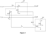
- the charging pile is a single-phase alternating current charging pile, and only a live wire is provided with a relay.
- the detection device is as shown in Figure 3 in a simplified way.
- the charging pile is a three-phase alternating current charging pile, and three live wires each are provided with a relay.
- the detection device is appliable to the single-phase alternating current charging pile including a live wire relay.
- the detection device is appliable to a three-phase alternating current charging pile including three live wire relays.
- the first signal input terminal Vin1 is configured to connect to the output side of the to-be-detected relay.
- the to-be-detected relay In a case that the to-be-detected relay is stuck, the to-be-detected relay is turned on, and a charging signal is applied to the detection module 100 via the first signal input terminal Vin1 and the second signal input terminal Vin2, so that a rectifying path in the detection module 100 outputs a rectified signal as the control signal for validation to the isolation output module 200.
- the to-be-detected relay is not stuck, the to-be-detected relay is turned off, and the charging signal fails to be applied to the detection module 100, so that the detection module 100 outputs no rectified signal, that is, the detection module 100 outputs the control signal for invalidation.
- the detection module 100 outputs the control signal based on the -on-off state of the to-be-detected relay (that is, a fact that the to-be-detected relay is or is not stuck), so as to establish a correspondence between a result of whether the to-be-detected relay is stuck and the control signal outputted by the detection module 100.
- the signal output terminal of the detection module 100 is connected to a control end of the isolation output module 200.
- the detection module 100 outputs the control signal depending on the on-off state of the to-be-detected relay (that is, a fact that the to-be-detected relay is or is not stuck).
- the control signal outputted by the detection module 100 changes periodically.
- the control signal is applied to the isolation output module 200, so that the isolation output module 200 outputs the detection signal with a duty cycle corresponding to the control signal.
- the isolation output module 200 outputs the detection signal with a certain duty cycle.
- the detection signal may be, for example, at a high or low level.
- the isolation output module 200 outputs the detection signal at a low level.
- the isolation output module 200 outputs the detection signal at a high level. Therefore, in a case that the detection module 100 outputs the control signal for validation and invalidation alternately, the isolation output module 200 outputs the detection signal with the certain duty cycle.
- the signal output terminal of the isolation output module 200 is configured to connect to the fault identification device.
- the isolation output module 200 outputs the detection signal with a duty cycle to the fault identification device, so that the fault identification device detects whether the to-be-detected relay is stuck based on the duty cycle of the detection signal. It can be seen from the above description that the control signal outputted by the detection module 100 in a case that the to-be-detected relay is stuck is different from the control signal outputted by the detection module 100 in a case that the to-be-detected relay is not stuck, so that the isolation output module 200 outputs the detection signal with a duty cycle.
- the duty cycle of the detection signal outputted by the isolation output module 200 are in a correspondence with the on-off state of the to-be-detected relay.
- the fault identification device detects whether at least one of the live wire relay and a neutral wire relay is stuck.
- the correspondence between the duty cycle of the detection signal and the on-off state of the to-be-detected relay is stored in the fault identification device.
- the fault identification device detects whether the to-be-detected relay is stuck by searching the correspondence based on the duty cycle of the detection signal. It can be seen that in the embodiment, the fault identification device can automatically detect whether a relay is stuck without an action of a relay.
- the fault identification device acts when a relay is detected as being stuck. For example, when detecting that a relay is stuck, the fault identification device outputs a control signal to control the alternating current charging pile to stop outputting the charging signal, so as to stop the charging.
- the fault identification device in the embodiment is implemented by a main control unit of the alternating current charging pile, or a main control unit (MCU) arranged outside the alternating current charging pile.
- the fault identification device is in communication connection with the main control unit of the charging pile, to feed back a result of adhesion detection on the relay to the main control unit of the charging pile.
- the charging pile performs control, for example, stopping charging, based on the result.
- the detection device for a relay includes a detection module.
- the detection module output a control signal to the isolation output module based on an on-off state of the to-be-detected relay.
- the isolation output module outputs a detection signal with a duty cycle to a fault identification device based on the control signal, to inform the fault identification device to detect based on the duty cycle of the detection signal whether the to-be-detected relay is stuck.
- the detection device according to the embodiment can perform adhesion detection on a relay without an action of a relay, having a simple circuit structure.
- the detection device can automatically outputs a detection signal with a duty cycle corresponding to a result of the adhesion detection, so that the fault identification device can automatically detect whether the to-be-detected relay is stuck. It is unnecessary to control a relay to be switched off, and therefore secondary hazards are avoided, thereby improving the safety of the alternating current charging pile.
- the detection module 100 includes a first unidirectional conduction unit D1 and a second unidirectional conduction unit D2.
- the number of the first unidirectional conduction unit D 1 is at least one.
- a first terminal of the first unidirectional conduction unit D1 serves as the first signal input terminal Vin1.
- a second terminal of all the first unidirectional conduction unit D1 is connected, serving as the signal output terminal Vout1 of the detection module 100.
- a first terminal of the second unidirectional conduction unit D2 serves as another signal output terminal Vout2 of the detection module 100.
- a second terminal of the second unidirectional conduction unit D2 serves as the second signal input terminal Vin2.
- the first terminal of the second unidirectional conduction unit D2 is the same as the first terminal of the first unidirectional conduction unit D 1.
- the unidirectional conduction unit may be, for example, a rectifier diode.
- the detection device including the detection module 100 is applicable to a single-phase alternating current charging pile including a live wire relay only.
- the detection device including the detection module 100 is applicable to a three-phase alternating current charging pile including three live wire relays only.
- the first terminal of the first unidirectional conduction unit D1 and the first terminal of the second unidirectional conduction unit D2 in the embodiment each are an anode or a cathode. That is, the anode of the first unidirectional conduction unit D1 serves as the first signal input terminal Vin1 of the detection module 100, and the cathode of the second unidirectional conduction unit D2 serves as the second signal input terminal Vin2 of the detection module 100.
- the cathode of the first unidirectional conduction unit D1 serves as the first signal input terminal Vin1 of the detection module 100, and the anode of the second unidirectional conduction unit D2 serves as the second signal input terminal Vin2 of the detection module 100. Therefore, in a case that the to-be-detected relay is stuck, a rectifying path is formed in the detection module 100, to outputs the control signal for validation to the isolation output module 200.
- the number of the first unidirectional conduction unit D1 is one and the anode of the first unidirectional conduction unit D1 serves as the first signal input terminal Vin1, the cathode of the second unidirectional conduction unit D2 serves as the second signal input terminal Vin2.
- a positive half cycle of an alternating current charging signal passes through a current path formed by the to-be-detected relay, the first unidirectional conduction unit D1, the control end of the isolation output module 200 and the second unidirectional conduction unit D2, so that the control signal for validation is outputted to the control end of the isolation output module 200.
- the isolation output module 200 outputs a detection signal with a duty cycle based on the control signal for validation. In a case that the to-be-detected relay is not stuck, the current path is cut off, and the alternating current charging signal fails to be transmitted through the detection module 100. In this case, the isolation output module 200 outputs the detection signal with another duty cycle.
- the fault identification device at a later stage can automatically detect based on the detection signal with the varying duty cycle whether the to-be-detected relay is stuck.
- the anode of the second unidirectional conduction unit D2 serves as the second signal input terminal Vin2.
- a negative half cycle of an alternating current charging signal passes through a current path formed by the second unidirectional conduction unit D2, the control end of the isolation output module 200, the first unidirectional conduction unit D1 and the to-be-detected relay, so that the control signal for validation is outputted to the control end of the isolation output module 200.
- the isolation output module 200 outputs a detection signal with a duty cycle based on the control signal for validation.
- the current path is cut off, and the alternating current charging signal fails to be transmitted through the detection module 100, so that the detection module 100 outputs the control signal for invalidation, to control the isolation output module 200 to output the detection signal with another duty cycle.
- the fault identification device at a later stage can automatically detect based on the detection signals with the varying duty cycle whether the to-be-detected relay is stuck.
- the detection device for a relay includes the unidirectional conduction unit, a first terminal of the first unidirectional conduction unit D1 serves as the first signal input terminal Vin1 and a second terminal of the second unidirectional conduction unit D2 serves as the second signal input terminal Vin2. Therefore, the detection module 100 can output the control signal corresponding to the on-off state of the to-be-detected relay based on the two unidirectional conduction units, to control the isolation output module 200 to output the detection signal with a varying duty cycle based on a fact that the to-be-detected relay is or is not stuck, so that the fault identification device can detect whether the to-be-detected relay is stuck.
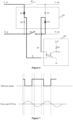
- Figure 4 is a structural block diagram of a detection device for a relay according to another embodiment of the present disclosure. Based on the above embodiment, as shown in Figure 4 , the number of the first unidirectional conduction unit D1 is one, and the detection module 100 further includes a third unidirectional conduction unit D3 and a fourth unidirectional conduction unit D4.
- An anode of the third unidirectional conduction unit D3 is connected to the anode of the second unidirectional conduction unit D2, and the common anode of the third unidirectional conduction unit D3 and the second unidirectional conduction unit D2 serves as a signal output terminal Vout2 of the detection module 100.
- a cathode of the fourth unidirectional conduction unit D4 is connected to the cathode of the first unidirectional conduction unit D1, and the common cathode of the fourth unidirectional conduction unit D4 and the first unidirectional conduction unit D1 serves as another signal output terminal Vout1 of the detection module 100.
- a cathode of the third unidirectional conduction unit D3 serves as a third signal input terminal Vin3 of the detection module 100.
- An anode of the fourth unidirectional conduction unit D4 serves as a fourth signal input terminal Vin4 of the detection module 100.
- the second signal input terminal Vin2 and the third signal input terminal Vin3 each serve as a signal input terminal of the detection module 100 connected to an input side of the to-be-detected relay.
- the first signal input terminal Vin1 and the fourth signal input terminal Vin4 each serve as a signal input terminal of the detection module 100 connected to the output side of the to-be-detected relay.
- the to-be-detected relay in the embodiment includes a live wire relay and a neutral wire relay, or include only a live wire relay. That is, the detection device according to the embodiment can not only perform adhesion detection on a relay in a single-phase alternating current charging pile including both a live wire relay and a neutral wire relay, but also perform adhesion detection on a relay in a single-phase alternating current charging pile including a live wire relay only.
- the detection module 100 performs adhesion detection on the live wire relay is stuck by detecting whether the first current path outputs a rectified signal (that is, the control signal for validation), and performs adhesion detection on the neutral wire relay by detecting whether the second current path outputs a rectified signal (that is, the control signal for validation). Whether the first current path outputs a rectified signal depends on whether the live wire relay is stuck, and whether the second current path outputs a rectified signal depends on whether the neutral wire relay is stuck.
- the detection module 100 can output a control signal corresponding to an on-off state of the relay to the isolation output module 200, to control the isolation output module 200 to output a detection signal with a duty cycle corresponding to the on-off state of the relay, so that the fault identification device at a later stage can automatically detect whether there is a relay being stuck.
- the detection signal outputted by the detection device further informs the fault identification device to detect based on the duty cycle of the detection signal whether both the live wire relay and the neutral wire relay each are stuck or one of the live wire relay and the neutral wire relay is stuck.
- the negative or positive half cycle of the alternating current charging signal passes through the relay that is stuck such that a first control signal is outputted to the control end of the isolation output module 200.
- the first control signal indicates validation and invalidation with a ratio of 1:1.
- the first control signal is applied to the isolation output module 200, so that the isolation output module 200 outputs a detection signal with a first duty cycle.
- the live wire relay and the neutral wire relay each are stuck in an on state
- the positive half cycle and the negative half cycle of the alternating current charging signals respectively passes through the two relays, such that a second control signal is outputted to the control end of the isolation output module 200.
- a proportion of validation in the second control signal is larger than that in the first control signal, so that a duty cycle of the detection signal outputted by the isolation output module 200 is smaller. Therefore, the fault identification device can detect based on the duty cycle of the detection signal whether one relay is stuck or two relays each are stuck.
- Figure 5 is a diagram showing a current path in a case that a relay is stuck according to an embodiment of the present disclosure.
- the live wire relay K3 is stuck.
- the positive half cycle of the alternating current charging signal passes through a rectifying path formed by the first unidirectional conduction unit D1 and the second unidirectional conduction unit D2.
- No rectifying path is formed for the negative half cycle of the alternating current charging signal.
- Figure 6 is a diagram showing a current path in a case that a relay is stuck according to another embodiment of the present disclosure.
- the neutral wire relay K4 is stuck
- the negative half cycle of the alternating current charging signal passes through a rectifying path formed by the third unidirectional conduction unit D3 and the fourth unidirectional conduction unit D4.
- a current path is formed with a combination of the current paths in the above two cases. That is, both the positive half cycle and the negative half cycle of the alternating current charging signal cause the detection module 100 to output the control signal for validation.
- the isolation output module 200 outputs the detection signal at a low level in a case that the detection module 100 outputs the control signal for validation, and the isolation output module 200 outputs the detection signal at a high level in a case that the detection module 100 outputs the control signal for invalidation.
- Figure 8 shows a detection signal in a case that the live wire relay K3 and the neutral wire relay K4 each are stuck.
- the isolation output module 200 outputs the detection signal with a duty cycle approximately ranging from 0 to 10% (where a signal input terminal of the detection module 100 is turned on only when a voltage passing through the signal input terminal of the detection module 100 is greater than a voltage drop of a switch transistor in the detection module, and therefore the duty cycle of the detection signal actually approximates zero).
- the fault identification device detects based on the duty cycle that the live wire relay K3 and the neutral wire relay K4 each are stuck. It can be seen that based on this, when none of the live wire relay K3 and the neutral wire relay K4 is stuck, the isolation output module 200 outputs the detection signal with a duty cycle approximating 100%.
- Figure 9 is a structural block diagram of a detection device for a relay according to another embodiment of the present disclosure. Based on the above embodiment, as shown in Figure 9 , the number of the first unidirectional conduction unit D1 is one, and the detection module 100 further includes a third unidirectional conduction unit D3 and a fourth unidirectional conduction unit D4.
- a cathode of the third unidirectional conduction unit D3 is connected to a cathode of the second unidirectional conduction unit D2, and the common cathode of the third unidirectional conduction unit D3 and the cathode of the second unidirectional conduction unit D2 serves as a signal output terminal Vout2 of the detection module 100.
- An anode of the fourth unidirectional conduction unit D4 is connected to an anode of the first unidirectional conduction unit D 1, and the common anode of the fourth unidirectional conduction unit D4 and the first unidirectional conduction unit D1 serves as another signal output terminal Vout1 of the detection module 100.
- An anode of the third unidirectional conduction unit D3 serves as a third signal input terminal Vin3 of the detection module 100.
- a cathode of the fourth unidirectional conduction unit D4 serves as a fourth signal input terminal Vin4 of the detection module 100.
- the second signal input terminal Vin2 and the third signal input terminal Vin3 each serve as a signal input terminal of the detection module 100 connected to the input side of the to-be-detected relay
- the first signal input terminal Vin1 and the fourth signal input terminal Vin4 each serve as a signal input terminal of the detection module 100 connected to the output side of the to-be-detected relay.
- the first unidirectional conduction unit D 1, the second unidirectional conduction unit D2, the third unidirectional conduction unit D3 and the fourth unidirectional conduction unit D4 in the above embodiment are reversely arranged, so that the detection module 100 has another circuit structure.
- the live wire relay if the live wire relay is stuck, the negative half cycle of the alternating current charging signal passes through a current path formed by the second unidirectional conduction unit D2 and the first unidirectional conduction unit D1, such that the control signal for validation is outputted. If the neutral wire relay is stuck, the positive half cycle of the alternating current charging signal through a current path formed by the third unidirectional conduction unit D3 and the fourth unidirectional conduction unit D4, such that the control signal for validation is outputted.
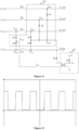
- Figure 10 is a structural block diagram showing a detection device for a relay according to another embodiment of the present disclosure. Based on the above embodiment, as shown in Figure 10 , the number of the first unidirectional conduction unit D1 is three, and the detection module 100 further includes a third unidirectional conduction unit D3 and a fourth unidirectional conduction unit D4.
- An anode of the third unidirectional conduction unit D3 is connected to an anode of the second unidirectional conduction unit D2, and the common anode of the third unidirectional conduction unit D3 and the second unidirectional conduction unit D2 serves as a signal output terminal Vout2 of the detection module 100.
- a cathode of the fourth unidirectional conduction unit D4 is connected to a cathode of the first unidirectional conduction unit D 1, and the common cathode of the fourth unidirectional conduction unit D4 and the first unidirectional conduction unit D1 serves as another signal output terminal Vout1 of the detection module 100.
- a cathode of the third unidirectional conduction unit D3 serves as a third signal input terminal Vin3 of the detection module 100.
- An anode of the fourth unidirectional conduction unit D4 serves as a fourth signal input terminal Vin4 of the detection module 100.
- the second signal input terminal Vin2 and the third signal input terminal Vin3 each serve as a signal input terminal of the detection module 100 connected to the input side of the to-be-detected relay.
- the first signal input terminal Vin1 and the fourth signal input terminal Vin4 each serve as a signal input terminal of the detection module 100 connected to the output side of the to-be-detected relay.
- the to-be-detected relay in the embodiment includes three live wire relays. That is, the detection device according to the embodiment is configured to perform adhesion detection on a relay in a three-phase four-wire alternating current charging pile including a neutral wire relay, and is also configured to perform adhesion detection on a relay in a three-phase four-wire alternating current charging pile including no neutral wire relay.
- the negative half cycle of the alternating current charging signal passes through a current path formed by the third unidirectional conduction unit D3 and the fourth unidirectional conduction unit D4, such that the control signal for validation is outputted to the control end of the isolation output module 200.
- a live wire relay among the three live wire relays is stuck, a positive half cycle of an alternating current charging signal of a live wire including the live wire relay that is stuck passes through a current path formed by a first unidirectional conduction unit D1 connected to the live wire relay that is stuck and the second unidirectional conduction unit D2, such that the control signal for validation is outputted to the control end of the isolation output module 200.
- the second unidirectional conduction unit D2 and the third unidirectional conduction unit D3 are arranged at the input side, and the three first unidirectional conduction units D1 and the fourth unidirectional conduction unit D4 are arranged at the output side, to perform adhesion detection on both the neutral wire relay K4 and the live wire relay.
- the detection device includes three third unidirectional conduction units configured to connect to input sides of the three live wire relays in one-to-one correspondence.
- the current path in a case that the neutral wire relay K4 is stuck is formed based on one third unidirectional conduction unit D3 only, so that the detection device can perform adhesion on either a live wire relay or a neutral wire relay, and has a simple circuit structure.
- each of the live wire relays is connected to one first unidirectional conduction unit D1, to form a current path for a current flowing through the live wire including the live wire relay in a case that the live wire relay is stuck, so as to perform the adhesion detection on the live wire relay.
- each of the three first unidirectional conduction units D1 is connected to the fourth unidirectional conduction unit D4, and the three first unidirectional conduction units D1 share one fourth unidirectional conduction unit D4 to form three output side bridge arms, which can also reduce the number of devices, thereby simplifying the circuit structure.
- the number of the fourth unidirectional conduction unit D4 is three, that is, the three first unidirectional conduction units D1 are connected to the three fourth unidirectional conduction units D4 in one-to-one correspondence, to form three output side bridge arms.
- the three first unidirectional conduction units D1 share one fourth unidirectional conduction unit D4 to form three output side bridge arms, so that the detection device is capable of adhesion detection based on a simple circuit structure.
- each of the unidirectional conduction units in the detection module 100 are reversely arranged to form a detection module 100 with another circuit structure, which is described below in combination with the drawings.
- Figure 11 is a structural block diagram of a detection device for a relay according to another embodiment of the present disclosure. Based on the above embodiment, as shown in Figure 11 , the number of the first unidirectional conduction unit D1 is three, and the detection module 100 further includes a third unidirectional conduction unit D3 and a fourth unidirectional conduction unit D4.
- a cathode of the third unidirectional conduction unit D3 is connected to a cathode of the second unidirectional conduction unit D2, and the common cathode of the third unidirectional conduction unit D3 and the second unidirectional conduction unit D2 serves as a signal output terminal Vout2 of the detection module 100.
- An anode of the fourth unidirectional conduction unit D4 is connected to an anode of the first unidirectional conduction unit D 1, and the anode of the fourth unidirectional conduction unit D4 is connected to the anode of the first unidirectional conduction unit D1 serves as another signal output terminal Vout1 of the detection module 100.
- An anode of the third unidirectional conduction unit D3 serves as a third signal input terminal Vin3 of the detection module 100.
- a cathode of the fourth unidirectional conduction unit D4 serves as a fourth signal input terminal Vin4 of the detection module 100.
- the second signal input terminal Vin2 and the third signal input terminal Vin3 each serve as a signal input terminal of the detection module 100 connected to the input side of the to-be-detected relay.
- the first signal input terminal Vin1 and the fourth signal input terminal Vin4 each serve as a signal input terminal of the detection module 100 connected to the output side of the to-be-detected relay.
- the detection module 100 in the embodiment is formed by reversely arranging all the unidirectional conduction units in the above embodiment.
- the detection module 100 can control the isolation output module 200 to output a detection signal with a duty cycle corresponding to a fact that at least one of a neutral wire relay and a live wire relay is stuck, so that the fault identification device at a later stage detects based on the duty cycle of the detection signal whether the to-be-detected relay is stuck.
- the detection device can not only detect whether a relay is stuck, but also find out a relay that is stuck.
- the principle of the detection is described below in combination with the drawings.
- the detection module 100 fails to output the control signal for validation to the isolation output module 200, and the isolation output module 200 outputs a detection signal with a duty cycle of 100%.
- the fault identification device detects that there is no relay being stuck.
- Figure 12 is a diagram showing a simulated detection signal in a case that one relay is stuck according to an embodiment of the present disclosure. It can be seen from Figure 12 that, in a case that one relay is stuck, the isolation output module 200 outputs the detection signal with a duty cycle approximating 50%. When detecting that the duty cycle of the detection signal approximates 50%, the fault identification device detects that there is one relay being stuck.
- Figures 13a to 13c each are a diagram showing a simulated detection signal in a case that two relays each are stuck according to an embodiment of the present disclosure.
- the isolation output module 200 outputs the detection signal with a duty cycle of 10%, as shown in Figure 13a .
- the isolation output module 200 outputs the detection signal with a duty cycle of 40%, as shown in Figure 13b .
- the isolation output module 200 outputs the detection signal with a duty cycle of 25%, as shown in Figure 13c .
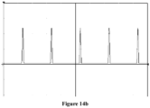
- FIGs 14a and 14b each are a diagram showing a simulated detection signal in a case that three relays each are stuck according to an embodiment of the present disclosure.
- a duty cycle of the detection signal is zero, which is similar to the case in which the four relays each are stuck, and the detection signal in this case is as shown in Figure 14a .
- the isolation output module 200 outputs the detection signal with a duty cycle of 12%, and the detection signal in this case is as shown in Figure 14b .
- the duty cycle of the detection signal is zero, and the detection signal is as shown in Figure 14a .
- FIG. 15 is a structural block diagram showing a detection device for a relay according to another embodiment of the present disclosure. Based on the above embodiment, as shown in Figure 15 , the detection device includes a detection module 100 and an isolation output module 200.
- the detection module 100 includes two first signal input terminals Vin1, one second signal input terminal Vin2, one third signal input terminal Vin3 and one fourth signal input terminal Vin4.
- One of the two first signal input terminals Vin1 is configured to connect to an output side of a first to-be-detected relay, and the other of the two first signal input terminals Vin1 is configured to connect to an output side of a second to-be-detected relay.
- the third signal input terminal Vin3 is configured to connect to an input side of one of the first and second to-be-detected relays.
- the second signal input terminal Vin2 is configured to connect to an input side of a third to-be-detected relay, and the fourth signal input terminal Vin4 is configured to connect to an output side of the third to-be-detected relay.
- Signal output terminals Vout1 and Vout2 of the detection module 100 each are connected to a control end of the isolation output module 200.
- the detection module 100 is configured to output a control signal based on an on-off state of a to-be-detected relay.
- a signal output terminal Vo of the isolation output module 200 is configured to connect to a fault identification device.
- the isolation output module 200 is configured to output a detection signal with a duty cycle corresponding to the control signal, to inform the fault identification device to detect whether the to-be-detected relay is stuck.
- the detection device is appliable to a three-phase three-wire alternating current charging pile.
- the three-phase three-wire alternating current charging pile includes three live wires and no zero wire.
- Each of the three live wires is provided with a live wire relay on the live wire. That is, the to-be-detected relay includes three live wire relays.
- the charging signal is applied to the detection module 100 through the first signal input terminal Vin1 and the second signal input terminal Vin2.
- the detection module 100 outputs a rectified signal as the control signal for validation to the control end of the isolation output module 200 through a rectifying path in the detection module 100, to control the isolation output module 200 to output the detection signal with a duty cycle.
- the charging signal is applied to the detection module 100 through the fourth signal input terminal Vin4 and the third signal input terminal Vin3.
- the detection module 100 outputs a rectified signal as the control signal for validation to the control end of the isolation output module 200 through another rectifying path in the detection module 100, to control the isolation output module 200 to output a detection signal with the duty cycle. In a case that none of the relays is stuck, the charging signal fails to be applied to the detection module 100.
- the detection module 100 outputs the control signal for invalidation, to control the isolation output module 200 to output the detection signal with another duty cycle.
- the fault identification device at a later stage detects based on the duty cycle of the detection signal whether there is a relay being stuck.
- the detection device is configured to perform adhesion detection on a relay in a three-phase three-wire alternating current charging pile.
- the detection module 100 includes two first unidirectional conduction units D1, a second unidirectional conduction unit D2, a third unidirectional conduction unit D3 and a fourth unidirectional conduction unit D4, as shown in Figure 15 .
- a first terminal of each of the two first unidirectional conduction units D1 serves as a first signal input terminal Vin1.
- Second terminals of the two first unidirectional conduction units D1 are connected to a second terminal of the fourth unidirectional conduction unit D4, and a node at which the second terminals of the two first unidirectional conduction units D1 are connected to the second terminal of the fourth unidirectional serves as a signal output terminal Vout1 of the detection module 100.
- a first terminal of the second unidirectional conduction unit D2 is connected to a first terminal of the third unidirectional conduction unit D3, and a node at which the first terminal of the second unidirectional conduction unit D2 is connected to the first terminal of the third unidirectional conduction unit D3 serves as another signal output terminal Vout2 of the detection module 100.
- a second terminal of the second unidirectional conduction unit D2 serves as a second signal input terminal Vin2.
- a second terminal of the third unidirectional conduction unit D3 serves as a third signal input terminal Vin3.
- the first terminals of the four unidirectional conduction units are identical in polarity.
- the first terminals of the four unidirectional conduction units each are an anode or a cathode. That is, the four unidirectional conduction units each may be reversely arranged, so that the detection module 100 has another circuit structure.
- the first terminals of the four unidirectional conduction units each are an anode.
- Figure 16 shows the detection module 100 in a case that the first terminals of the four unidirectional conduction units each are a cathode.
- the detection device is capable of finding out a relay that is stuck, which is further described below in combination with the drawings.
- the isolation output module 200 outputs the detection signal with a duty cycle approximating 50%.
- the fault identification device detects that there is one relay being stuck.
- the fault identification device finds the two relays each being stuck out based on the duty cycle of the detection signal.
- the isolation output module 200 outputs the detection signal with a duty cycle of 10%, and the detection signal in this case is as shown in Figure 13a .
- the isolation output module 200 outputs the detection signal with a duty cycle of 40%, and the detection signal in this case is as shown in Figure 13b .
- the isolation output module 200 outputs the detection signal with a duty cycle of 25%, and the detection signal in this case is as shown in Figure 13c .
- the detection module 100 fails to output the control signal for validation to the isolation output module 200, and the isolation output module 200 outputs the detection signal with a duty cycle of 100%.
- the fault identification device detects that no relay is stuck.
- the controllable switch is connected between the signal output terminal Vout1 or Vout2 of the detection module 100 and the control end of the isolation output module 200, and a control terminal of the controllable switch is connected to the fault identification device.
- the controllable switch controls, in response to the fault identification device, the detection device to start or end adhesion detection.
- the live wire relay and the neutral wire relay K4 are on, and therefore it is unnecessary to perform adhesion detection in the process.
- the adhesion detection is performed only when the alternating current charging pile stops charging or starts charging. In a case of no controllable switch S, the detection device operates throughout the process that the alternating current charging pile performs charging, which lasts for a long time period, resulting in high power consumption and unnecessary waste of resources.
- controllable switch S in this embodiment is applicable to the single-phase alternating current charging pile, the three-phase four-wire alternating current charging pile and the three-phase three-wire alternating current charging pile described above. That is, for each of the single-phase alternating current charging pile, the three-phase four-wire alternating current charging pile and the three-phase three-wire alternating current charging pile, the controllable switch according to the embodiment is provided to control the detection device.
- controllable switch S is connected between the signal output terminal of the detection module 100 and the control terminal of the isolation output module 200, to switch states of the detection device.
- the controllable switch S is controlled to be turned on when the charging pile is to perform charging or to stop charging, to control the detection device to perform adhesion detection on a relay. During the process that the charging pile performs charging, the detection device is off, so as to reduce power consumption of the detection device.
- the detection device further includes a current limiting resistor R1.
- One terminal of the current limiting resistor R1 is connected to one of the signal output terminals Vout1 and Vout2 of the detection module 100, and the other terminal of the current limiting resistor R1 is connected to one terminal of the control end of the detection module 100.
- the current limiting resistor R1 is connected in series to an output loop of the detection module 100, to limit a current outputted from the detection module 100, so as to output a detection signal that meets requirements, thereby preventing an amplitude of the control signal from being out of a range of the isolation output module 200.
- the isolation output module 200 includes an optocoupler.
- An anode and a cathode of a light-emitting diode of the optocoupler respectively serve as two terminals at the control end of the isolation output module 200.
- a collector of a phototransistor of the optocoupler is connected to a preset voltage as a signal output terminal Vo of the isolation output module 200, and an emitter of the phototransistor of the optocoupler is grounded.
- the phototransistor at a secondary side of the optocoupler is turned on.
- the primary side of the optocoupler serves as the control end of the isolation output module 200.
- the detection module 100 outputs the control signal for validation, the light-emitting diode at the primary side of the optocoupler is turned on, and the phototransistor at the secondary side of the optocoupler operates.
- the optocoupler outputs a control signal at a high or low level, depending on a circuit connected to the secondary side, as the detection signal of the isolation output module 200.
- control signal outputted by the detection module 100 periodically changes, and thus the detection signal outputted from the secondary side of the optocoupler periodically changes.
- a duty cycle of the detection signal outputted from the secondary side indicates a result of whether there is a relay being stuck. Therefore, it is detected based on the duty cycle of the detection signal outputted from the secondary side of the optocoupler whether there is a relay being stuck.
- the collector of the phototransistor of the optocoupler is connected to the preset voltage, as the signal output terminal Vo of the isolation output module 200, and the emitter of the phototransistor of the optocoupler is grounded.
- the signal output terminal Vo outputs the preset voltage, this is, a signal at a high level.
- the signal output terminal Vo is grounded and thereby outputs a signal at a low level. Therefore, the fault identification device detects based on the duty cycle of the detection signal whether the to-be-detected relay is stuck.
- a direction in which the light-emitting diode is connected depends on a direction in which the unidirectional conduction unit in the detection module 100 is arranged, so that the rectified signal outputted by the detection module 100 can be applied to the light-emitting diode.
- the collector of the phototransistor of the optocoupler is connected to a first terminal of a pull-up resistor R2, a second terminal of the pull-up resistor R2 is connected to a pull-up voltage, and the first terminal of the pull-up resistor R2 outputs a preset voltage V0.
- the pull-up voltage is 3.3V.
- the pull-up voltage of 3.3V is divided by the pull-up resistor R2, such that the preset voltage V0 is outputted.
- the detection module 100 outputs the control signal for invalidation, the light-emitting diode is turned off, the phototransistor does not operate, and the optocoupler outputs the preset voltage V0, that is, outputs the detection signal at a high level.
- the detection module 100 outputs the control signal for validation, the light-emitting diode is turned on and the phototransistor operates, and the optocoupler outputs the detection signal at a low level.
- Figure 17 is a flowchart showing a method for inspecting a relay according to an embodiment of the present disclosure. The method is applied to the detection device for a relay according to any one of the embodiments described above. As shown in Figure 17 , the method includes the following steps S110 and S120.
- step 5110 the detection module outputs a control signal based on an on-off state of a to-be-detected relay.
- a control signal outputted by the detection module corresponds to an on-off state of a live wire relay and of a neutral wire relay (that is, a result that whether there is a relay being stuck). In a case that a relay is stuck, the detection module outputs the control signal for validation. In a case that no relay is stuck, the detection module outputs the control signal for invalidation.
- step S120 the isolation output module outputs a detection signal with a duty cycle corresponding to the control signal, to inform the fault identification device to detect whether the to-be-detected relay is stuck.
- the duty cycle of the detection signal outputted by the isolation output module varies with the control signal outputted by the detection module.
- the duty cycle of the detection signal corresponds to a result of whether the to-be-detected relay is stuck. Therefore, the fault identification device detects based on the duty cycle of the detection signal whether there is a relay being stuck.
- the alternating current charging pile is to stop charging so as to ensure safety of the charging.
- the charging pile is controlled to stop charging according to the conventional technology, which is not described in detail in the embodiment.
- the detection module output a rectifier signal varying with a result of whether the to-be-detected relay is stuck.
- the rectified signal serves as the control signal to be transmitted to the control end of the isolation output module, so that the isolation output module outputs the detection signal with a varying duty cycle. That is, the duty cycle of the detection signal corresponds to a result of whether there is a relay being stuck. Therefore, the fault identification device detects whether there is a relay being stuck based on the duty cycle of the detection signal.
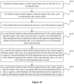
- Figure 18 is a flowchart showing a method for inspecting a relay according to another embodiment of the present disclosure. Based on the above embodiment, the method according to the embodiment is especially suitable for adhesion detection on a relay in the single-phase alternating unit charging pile. As shown in Figure 18 , the method includes the following steps S210 to S260.
- step S210 the detection module outputs a control signal based on an on-off state of a to-be-detected relay.
- step S220 the isolation output module outputs a detection signal with a duty cycle corresponding to the control signal.
- step S230 the fault identification device detects the duty cycle of the detection signal.
- step S240 in a case that the isolation output module outputs, a detection signal with a duty cycle less than or equal to a first threshold, the fault identification device detects based on the detection signal that the number of the to-be-detected relay is two and both the two to-be-detected relay are stuck.
- the first threshold is 10%. Due to a voltage drop of a switch transistor in the detection module, the signal input terminal of the detection module 100 is turned on only when a voltage passing through the signal input terminal of the detection module is greater than the voltage drop of the switch transistor, and therefore the duty cycle of the detection signal actually approximates zero. That is, when detecting that the duty cycle of the detection signal is less than or approximating 10%, the fault identification device detects that a present to-be-detected relay includes a live wire relay and a neutral relay and the live wire relay and the neutral relay each are stuck.
- step S250 in a case that the isolation output module outputs, based on the control signal, a detection signal with a duty cycle greater than the first threshold and less than or equal to a second threshold, the fault identification device detects based on the detection signal that the number of the to-be-detected relay is two and one of the two to-be-detected relays is stuck.
- the second threshold is 50%. That is, in a case that the isolation output module outputs a detection signal with a duty cycle less than or approximating 50%, the fault identification device detects that the to-be-detected relay includes a live wire relay and a neutral wire relay, and one of the live wire relay and the neutral wire relay is stuck.
- step S260 in a case that the isolation output module outputs, based on the control signal, a detection signal with a duty cycle greater than the second threshold and less than or equal to a third threshold, the fault identification device detects, based on the detection signal, that none of the to-be-detected relay is stuck.
- the third threshold is 100%.
- the isolation output module outputs a signal at a high level, indicating that the detection module outputs a control signal for invalidation, that is, no relay is stuck.
- the method for inspecting a relay in a case that it is detected based on the duty cycle of the detection signal outputted by the isolation output module that a relay is stuck, it is further detected based on the duty cycle of the detection signal whether one relay is stuck or two relays each are stuck.
- Figure 19 is a flowchart showing a method for inspecting a relay according to another embodiment of the present disclosure. Based on the above embodiment, the method according to this embodiment is especially suitable for adhesion detection on a relay in a three-phase charging pile. That is, the method in this embodiment is applicable to both a three-phase four-wire charging pile and a three-phase three-wire charging pile. As shown in Figure 19 , the method includes the following steps S310 to S400.
- step S310 the detection module output a control signal based on an on-off state of a to-be-detected relay.
- step S320 the isolation output module outputs a detection signal with a duty cycle corresponding to the control signal.
- step S330 the fault identification device detects the duty cycle of the detection signal.
- step S340 in a case that the isolation output module outputs, based on the control signal, a detection signal with a duty cycle less than or equal to a fourth threshold, the fault identification device detects based on the detection signal that at least all live wire relays each are stuck.
- the fourth threshold is zero, and a waveform of the detection signal is shown in Figure 14a in the above device embodiment.
- the fault identification device detects that all live wire relays each are stuck and the neutral wire relay is not stuck, or the neutral wire relay and all the live wire relays each are stuck.
- the fault identification device detects that all live wire relays each are stuck.
- step S350 in a case that the isolation output module outputs, based on the control signal, a detection signal with a duty cycle greater than the fourth threshold and less than or equal to a fifth threshold, the fault identification device detects based on the detection signal that at least a live wire relay having an input side connected to a signal input terminal is stuck.
- the fifth threshold is 10%
- the detection signal in this case is as shown in Figure 13 a.
- the fault identification device detects that the neutral line relay and a live wire relay having an input side connected to a signal input terminal each are stuck.
- the relays K3 and K4 shown in Figure 10 each are stuck.
- the fault identification device detects that all live wire relay each having an input side connected to a signal input terminal is stuck.
- the relays K2 and K3 shown in Figure 15 each are stuck.
- step S360 in a case that the isolation output module outputs, based on the control signal, a detection signal with a duty cycle greater than the fifth threshold and less than or equal to a sixth threshold, the fault identification device detects based on the detection signal that the neutral wire relay and two of the live wire relays each are stuck.
- the sixth threshold is 12%, and the fault identification device detects that the neutral wire relay and two of the live wire relays each are stuck.
- step S370 in a case that the isolation output module outputs, based on the control signal, a detection signal with a duty cycle greater than the sixth threshold and less than or equal to a seventh threshold, the fault identification device detects based on the detection signal that two of the three live wire relays each are stuck.
- the seventh threshold is 25%.
- the fault identification device detects that two of the three live wire relays each are stuck in this case.
- the fault identification device detects that two relays each are stuck, and the two relays each having an output side connected to a node, at which unidirectional conduction units are connected via the same terminal, as a signal input terminal.
- step S380 in a case that the isolation output module outputs, based on the control signal, a detection signal with a duty cycle greater than the seventh threshold and less than or equal to an eighth threshold, the fault identification device detects based on the detection signal that at least a live wire relay having an input side not connected to a signal input terminal is stuck.
- the eighth threshold is 40%.
- the fault identification device detects that the neutral wire relay and a live wire relay having an input side not connected to a signal input terminal each are stuck.
- the fault identification device detects that two relays each are stuck. An input side of one of the two relays is not connected to a signal input terminal, and an output side of the other of the two relays is connected to a node, at which unidirectional conduction units are connected with the same terminal, as a signal input terminal.
- the relays K 1 and K4 or the relays K2 and K4 shown in Figure 10 each are stuck.
- the relays K1 and K3 shown in Figure 15 each are stuck.
- step S390 in a case that the isolation output module outputs, based on the control signal, a detection signal with a duty cycle greater than the eighth threshold and less than or equal to a ninth threshold, the fault identification device detects based on the detection signal that one relay is stuck.
- the ninth threshold is 50%. In this case, for either a three-phase four-wire charging pile or a three-phase three-wire charging pile, the fault identification device detects that only one relay is stuck.
- step S400 in a case that the isolation output module outputs a detection signal with a duty cycle greater than the ninth threshold and less than or equal to a tenth threshold, the fault identification device detects based on the detection signal that none of all the to-be-detected relay is stuck.
- the tenth threshold is 100%. In this case, for either a three-phase four-wire charging pile or a three-phase three-wire charging pile, the fault identification device detects that no relay is stuck.
- the method for inspecting a relay it is detected whether a relay in a three-phase charging pile is stuck, and it is further found out based on a comparison result between the duty cycle of the detection signal and a preset threshold a relay that is stuck.
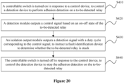
- FIG 20 is a flowchart showing a method for inspecting a relay according to another embodiment of the present disclosure.
- a controllable switch is arranged according to this embodiment, to control the detection device, for example, to start detection or stop detection before alternating current charging pile starts charging or after the alternating current charging pile stops charging, As shown in Figure 20 , the method includes the following steps S410 to S440.
- step S410 the controllable switch is turned on in response to a control device, to control the detection device perform adhesion detection on a to-be-detected relay.
- the detection device includes a controllable switch.
- the controllable switch is connected between a signal output terminal of the detection module and the control end of the isolation output module.
- a control terminal of the controllable switch is in communication connection with the control device.
- the control device is a fault identification device, for example, a main control unit of the alternating current charging pile, or other device outside the alternating current charging pile, for example, a cloud server.
- the controllable switch is manually controlled to be turned on or off.
- the detection device When the controllable switch is turned on, the detection device starts to operate.
- the detection device outputs a control signal depending on a result of whether the a relay is stuck, to control the isolation output module to output a detection signal a varying duty cycle, so that the fault identification device can detect based on the duty cycle of the detection signal whether there is a relay being stuck and the number of the relay that is stuck.
- controllable switch performs self-inspection in a process the charging pile performs charging.
- the self-inspection includes: receiving, by the controllable switch, a command for turning off the controllable switch from the control device; and detecting, by the control device, that the controllable switch is stuck in a case that the isolation output module outputs a predetermined detection signal in the process that the charging pile performs charging.
- the relay is on, and the detection module outputs the control signal for validation, so that the isolation output module outputs a signal at a low level. That is, the detection device outputs a detection signal of a duty cycle of zero throughout the process that the charging pile performs charging normally.
- the isolation output module outputs a signal at a high level, that is, the detection device outputs a detection signal with a duty cycle of 100%. In this case, if the detection device outputs the detection signal with a duty cycle of zero, it is detected that the controllable switch is stuck.
- step S420 the detection module output a control signal based on an on-off state of a to-be-detected relay.
- step S430 the isolation output module outputs a detection signal with a duty cycle corresponding to the control signal, to inform the fault identification device to detect whether the to-be-detected relay is stuck.
- step S440 the controllable switch is turned off in response to the control device, to control the detection device to stop the adhesion detection on the to-be-detected relay.
- control device transmits the command for turning off the controllable switch to the controllable switch, to inform the controllable switch to be turned off, and control the detection device to stop the adhesion detection.
- the detection device is provided with a controllable switch, to control the detection device to start or end the adhesion detection.
- whether the controllable switch is stuck is detected by self-inspection in the process that the charging pile performs charging.
- a charging pile is further provided according to an embodiment of the present disclosure.
- the charging pile includes the detection device for a relay according to any one of the above embodiments. Therefore, this embodiment has the same beneficial effects as any of the above embodiments.
Landscapes
- Physics & Mathematics (AREA)
- General Physics & Mathematics (AREA)
- Testing Of Short-Circuits, Discontinuities, Leakage, Or Incorrect Line Connections (AREA)
Claims (14)
- Detektionsvorrichtung für ein Relais, umfassend: ein Detektionsmodul (100) und ein Isolationsausgangsmodul (200), wobei,das Detektionsmodul (100) einen ersten Signaleingangsanschluss (Vin1) und einen zweiten Signaleingangsanschluss (Vin2) umfasst, wobei die Anzahl des ersten Signaleingangsanschlusses (Vin1) mindestens eins ist, der erste Signaleingangsanschluss (Vin1) so konfiguriert ist, dass er mit einer Ausgangsseite eines zu erfassenden Relais verbunden ist, der zweite Signaleingangsanschluss (Vin2) so konfiguriert ist, dass er mit einem Nullleiter verbunden ist, ein Signalausgangsanschluss (Vout1, Vout2) des Detektionsmoduls (100) so konfiguriert ist, dass er mit einem Steuerende des Isolationsausgangsmoduls (200) verbunden ist, und das Detektionsmodul (100) so konfiguriert ist, dass es ein Steuersignal auf der Grundlage eines Ein-Aus-Zustands des zu erfassenden Relais ausgibt; gekennzeichnet dadurch durch, dassein Signalausgangsanschluss (Vo) des Isolationsausgangsmoduls (200) so konfiguriert ist, dass er mit einer Fehleridentifizierungsvorrichtung verbunden ist, und das Isolationsausgangsmodul (200) so konfiguriert ist, dass es ein Erfassungssignal mit einem Tastverhältnis ausgibt, das dem Steuersignal entspricht, um die Fehleridentifizierungsvorrichtung zu informieren, um zu erfassen, ob das zu erfassende Relais klemmt, wobei die Detektionsvorrichtung ferner einen steuerbaren Schalter (S) umfasst, der zwischen dem Signalausgangsanschluss (Vout1, Vout2) des Detektionsmoduls (100) und dem Steuerende des Isolationsausgangsmoduls (200) verbunden ist, ein Steueranschluss des steuerbaren Schalters (S) so konfiguriert ist, dass er mit der Fehleridentifizierungsvorrichtung verbunden ist, und der steuerbare Schalter (S) so konfiguriert ist, dass er in Reaktion auf die Fehleridentifizierungsvorrichtung die Detektionsvorrichtung so steuert, dass sie eine Adhäsionserfassung startet oder stoppt.
- Detektionsvorrichtung für ein Relais nach Anspruch 1, wobei das Detektionsmodul (100) eine erste unidirektionale Leitungseinheit (D1) und eine zweite unidirektionale Leitungseinheit (D2) umfasst, wobeidie Anzahl der ersten unidirektionalen Leitungseinheit (D1) mindestens eins ist;ein erster Anschluss der mindestens einen ersten unidirektionalen Leitungseinheit (D1) als der erste Signaleingangsanschluss (Vin1) dient, und ein zweiter Anschluss der mindestens einen ersten unidirektionalen Leitungseinheit (D1) als ein Signalausgangsanschluss (Vout1) des Detektionsmoduls (100) zusammengeschaltet ist; undein erster Anschluss der zweiten unidirektionalen Leitungseinheit (D2) als ein weiterer Signalausgangsanschluss (Vout2) des Detektionsmoduls (100) dient, ein zweiter Anschluss der zweiten unidirektionalen Leitungseinheit (D2) als der zweite Signaleingangsanschluss (Vin2) dient, und der erste Anschluss der zweiten unidirektionalen Leitungseinheit (D2) in der Polarität identisch mit dem ersten Anschluss der ersten unidirektionalen Leitungseinheit (D1) ist.
- Detektionsvorrichtung für ein Relais nach Anspruch 2, wobeidie Anzahl der ersten unidirektionalen Leitungseinheit (D1) eins ist, und das Detektionsmodul (100) weiterhin eine dritte unidirektionale Leitungseinheit (D3) und eine vierte unidirektionale Leitungseinheit (D4) umfasst, wobei eine Anode der dritten unidirektionalen Leitungseinheit (D3) mit einer Anode der zweiten unidirektionalen Leitungseinheit (D2) verbunden ist, und die gemeinsame Anode der dritten unidirektionalen Leitungseinheit (D3) und der zweiten unidirektionalen Leitungseinheit (D2) als Signalausgangsanschluss (Vout2) des Detektionsmoduls (100) dient; eine Kathode der vierten unidirektionalen Leitungseinheit (D4) mit einer Kathode der ersten unidirektionalen Leitungseinheit (D1) verbunden ist, und die gemeinsame Kathode der vierten unidirektionalen Leitungseinheit (D4) und der ersten unidirektionalen Leitungseinheit (D1) als ein weiterer Signalausgangsanschluss (Vout1) des Detektionsmoduls (100) dient; eine Kathode der dritten unidirektionalen Leitungseinheit (D3) als ein dritter Signaleingangsanschluss (Vin3) des Detektionsmoduls (100) dient; und eine Anode der vierten unidirektionalen Leitungseinheit (D4) als ein vierter Signaleingangsanschluss (Vin4) des Detektionsmoduls (100) dient; undder zweite Signaleingangsanschluss (Vin2) und der dritte Signaleingangsanschluss (Vin3) jeweils als ein Signaleingangsanschluss des Detektionsmoduls (100) dienen, der konfiguriert ist, um mit einer Eingangsseite des zu erfassenden Relais verbunden zu werden, und der erste Signaleingangsanschluss (Vin1) und der vierte Signaleingangsanschluss (Vin4) jeweils als ein Signaleingangsanschluss des Detektionsmoduls (100) dienen, der konfiguriert ist, um mit der Ausgangsseite des zu erfassenden Relais verbunden zu werden.
- Detektionsvorrichtung für ein Relais nach Anspruch 2, wobeidie Anzahl der ersten unidirektionalen Leitungseinheit (D1) eins ist, und das Detektionsmodul (100) ferner eine dritte unidirektionale Leitungseinheit (D3) und eine vierte unidirektionale Leitungseinheit (D4) umfasst, und wobei eine Kathode der dritten unidirektionalen Leitungseinheit (D3) mit einer Kathode der zweiten unidirektionalen Leitungseinheit (D2) verbunden ist und die gemeinsame Kathode der dritten unidirektionalen Leitungseinheit (D3) und der zweiten unidirektionalen Leitungseinheit (D2) als ein Signalausgangsanschluss (Vout2) des Detektionsmoduls (100) dient; eine Anode der vierten unidirektionalen Leitungseinheit (D4) mit einer Anode der ersten unidirektionalen Leitungseinheit (D1) verbunden ist und die gemeinsame Anode der vierten unidirektionalen Leitungseinheit (D4) und der ersten unidirektionalen Leitungseinheit (D1) als ein weiterer Signalausgangsanschluss (Vout1) des Detektionsmoduls (100) dient; eine Anode der dritten unidirektionalen Leitungseinheit (D3) als ein dritter Signaleingangsanschluss (Vin3) des Detektionsmoduls (100) dient; und eine Kathode der vierten unidirektionalen Leitungseinheit (D4) als ein vierter Signaleingangsanschluss (Vin4) des Detektionsmoduls (100) dient; undder zweite Signaleingangsanschluss (Vin2) und der dritte Signaleingangsanschluss (Vin3) jeweils als ein Signaleingangsanschluss des Detektionsmoduls (100) dienen, der konfiguriert ist, um mit einer Eingangsseite des zu erfassenden Relais verbunden zu werden, und der erste Signaleingangsanschluss (Vin1) und der vierte Signaleingangsanschluss (Vin4) jeweils als ein Signaleingangsanschluss des Detektionsmoduls (100) dienen, der konfiguriert ist, um mit der Ausgangsseite des zu erfassenden Relais verbunden zu werden.
- Detektionsvorrichtung für ein Relais nach Anspruch 2, wobeidie Anzahl der ersten unidirektionalen Leitungseinheit (D1) drei beträgt, und das Detektionsmodul (100) ferner eine dritte unidirektionale Leitungseinheit (D3) und eine vierte unidirektionale Leitungseinheit (D4) umfasst, und wobei eine Anode der dritten unidirektionalen Leitungseinheit (D3) mit einer Anode der zweiten unidirektionalen Leitungseinheit (D2) verbunden ist und die gemeinsame Anode der dritten unidirektionalen Leitungseinheit (D3) und der zweiten unidirektionalen Leitungseinheit (D2) als ein Signalausgangsanschluss (Vout2) des Detektionsmoduls (100) dient; eine Kathode der vierten unidirektionalen Leitungseinheit (D4) mit Kathoden der drei ersten unidirektionalen Leitungseinheiten (D1) verbunden ist, und die gemeinsame Kathode der vierten unidirektionalen Leitungseinheit (D4) und der drei ersten unidirektionalen Leitungseinheiten (D1) als ein weiterer Signalausgangsanschluss (Vout1) des Erfassungsmoduls (100) dient; eine Kathode der dritten unidirektionalen Leitungseinheit (D3) als ein dritter Signaleingangsanschluss (Vin3) des Detektionsmoduls (100) dient; und eine Anode der vierten unidirektionalen Leitungseinheit (D4) als ein vierter Signaleingangsanschluss (Vin4) des Detektionsmoduls (100) dient; undder zweite Signaleingangsanschluss (Vin2) und der dritte Signaleingangsanschluss (Vin3) jeweils als ein Signaleingangsanschluss des Erfassungsmoduls (100) dienen, der konfiguriert ist, um mit einer Eingangsseite des zu erfassenden Relais verbunden zu werden, und der erste Signaleingangsanschluss (Vin1) und der vierte Signaleingangsanschluss (Vin4) jeweils als ein Signaleingangsanschluss des Erfassungsmoduls (100) dienen, der konfiguriert ist, um mit der Ausgangsseite des zu erfassenden Relais verbunden zu werden.
- Detektionsvorrichtung für ein Relais nach Anspruch 2, wobeidie Anzahl der ersten unidirektionalen Leitungseinheiten (D1) drei beträgt, und das Detektionsmodul (100) ferner eine dritte unidirektionale Leitungseinheit (D3) und eine vierte unidirektionale Leitungseinheit (D4) umfasst, und wobei eine Kathode der dritten unidirektionalen Leitungseinheit (D3) mit einer Kathode der zweiten unidirektionalen Leitungseinheit (D2) verbunden ist und die gemeinsame Kathode der dritten unidirektionalen Leitungseinheit (D3) und der zweiten unidirektionalen Leitungseinheit (D2) als ein Signalausgangsanschluss (Vout2) des Detektionsmoduls (100) dient; eine Anode der vierten unidirektionalen Leitungseinheit (D4) mit einer Anode der ersten unidirektionalen Leitungseinheit (D1) verbunden ist und die gemeinsame Anode der vierten unidirektionalen Leitungseinheit (D4) und der ersten unidirektionalen Leitungseinheit (D1) als ein weiterer Signalausgangsanschluss (Vout1) des Detektionsmoduls (100) dient; eine Anode der dritten unidirektionalen Leitungseinheit (D3) als ein dritter Signaleingangsanschluss (Vin3) des Detektionsmoduls (100) dient; und eine Kathode der vierten unidirektionalen Leitungseinheit (D4) als ein vierter Signaleingangsanschluss (Vin4) des Detektionsmoduls (100) dient; undder zweite Signaleingangsanschluss (Vin2) und der dritte Signaleingangsanschluss (Vin3) jeweils als ein Signaleingangsanschluss des Detektionsmoduls (100) dienen, der konfiguriert ist, um mit einer Eingangsseite des zu erfassenden Relais verbunden zu werden, und der erste Signaleingangsanschluss (Vin1) und der vierte Signaleingangsanschluss (Vin4) jeweils als ein Signaleingangsanschluss des Detektionsmoduls (100) dienen, der konfiguriert ist, um mit der Ausgangsseite des zu erfassenden Relais verbunden zu werden.
- Detektionsvorrichtung für ein Relais nach einem der Ansprüche 1 bis 6, wobei,das Isolationsausgangsmodul (200) einen Optokoppler umfasst, wobei,eine Anode und eine Kathode einer lichtemittierenden Diode des Optokopplers jeweils als zwei Anschlüsse an der Steuerseite des Isolationsausgangsmoduls (200) dienen; undein Kollektor eines Fototransistors des Optokopplers so konfiguriert ist, dass er mit einer voreingestellten Spannung als der Signalausgangsanschluss (Vo) des Isolationsausgangsmoduls (200) verbunden ist, und ein Emitter des Fototransistors des Optokopplers geerdet ist.
- Detektionsvorrichtung für ein Relais, umfassend: ein Detektionsmodul (100) und ein Isolationsausgangsmodul (200), wobei,das Detektionsmodul (100) zwei erste Signaleingangsanschlüsse (Vin1), einen zweiten Signaleingangsanschluss (Vin2), einen dritten Signaleingangsanschluss (Vin3) und einen vierten Signaleingangsanschluss (Vin4) umfasst, wobei die beiden ersten Signaleingangsanschlüsse (Vin1) so konfiguriert sind, dass sie jeweils mit den Ausgangsseiten von zwei zu erfassenden Relais verbunden sind, der dritte Signaleingangsanschluss (Vin3) so konfiguriert ist, dass er mit einer Eingangsseite eines der beiden zu erfassenden Relais verbunden ist, der zweite Signaleingangsanschluss (Vin2) und der vierte Signaleingangsanschluss (Vin4) so konfiguriert sind, dass sie mit einer Eingangsseite bzw.einer Ausgangsseite eines anderen zu erfassenden Relais verbunden sind;ein Signalausgangsanschluss (Vout1, Vout2) des Detektionsmoduls (100) mit einem Steuerende des Isolationsausgangsmoduls (200) verbunden ist, und das Detektionsmodul (100) so konfiguriert ist, dass es ein Steuersignal auf der Grundlage eines Ein-Aus-Zustands eines zu erfassenden Relais ausgibt;gekennzeichnet dadurch, dassein Signalausgangsanschluss (Vo) des Isolationsausgangsmoduls (200) so konfiguriert ist, dass er mit einer Fehleridentifizierungsvorrichtung verbunden ist, und das Isolationsausgangsmodul (200) so konfiguriert ist, dass es ein Erfassungssignal mit einem Tastverhältnis ausgibt, das dem Steuersignal entspricht, um die Fehleridentifizierungsvorrichtung zu informieren, um zu erfassen, ob ein zu erfassendes Relais klemmt, wobei die Detektionsvorrichtung ferner einen steuerbaren Schalter (S) umfasst, der zwischen dem Signalausgangsanschluss (Vout1, Vout2) des Detektionsmoduls (100) und dem Steuerende des Isolationsausgangsmoduls (200) verbunden ist, ein Steueranschluss des steuerbaren Schalters (S) so konfiguriert ist, dass er mit der Fehleridentifizierungsvorrichtung verbunden ist, und der steuerbare Schalter (S) so konfiguriert ist, dass er in Reaktion auf die Fehleridentifizierungsvorrichtung die Detektionsvorrichtung so steuert, dass sie eine Adhäsionserfassung startet oder stoppt.
- Detektionsvorrichtung für ein Relais nach Anspruch 8, wobeidas Detektionsmodul (100) zwei erste unidirektionale Leitungseinheiten (D1), eine zweite unidirektionale Leitungseinheit (D2), eine dritte unidirektionale Leitungseinheit (D3) und eine vierte unidirektionale Leitungseinheit (D4) umfasst;erste Anschlüsse der ersten unidirektionalen Leitungseinheiten (D1) jeweils als die zwei ersten Signaleingangsanschlüsse (Vin1) dienen, zweite Anschlüsse der zwei ersten unidirektionalen Leitungseinheiten (D1) mit einem zweiten Anschluss der vierten unidirektionalen Leitungseinheit (D4) als ein Signalausgangsanschluss (Vout1) des Detektionsmoduls (100) verbunden sind;ein erster Anschluss der zweiten unidirektionalen Leitungseinheit (D2) mit einem ersten Anschluss der dritten unidirektionalen Leitungseinheit (D3) als ein weiterer Signalausgangsanschluss (Vout2) des Detektionsmoduls (100) verbunden ist; und ein zweiter Anschluss der zweiten unidirektionalen Leitungseinheit (D2) als der zweite Signaleingangsanschluss (Vin2) dient, und ein zweiter Anschluss der dritten unidirektionalen Leitungseinheit (D3) als der dritte Signaleingangsanschluss (Vin3) dient; unddie jeweiligen ersten Anschlüsse der vier unidirektionalen Leitungseinheiten (D1, D2, D3, D4) in ihrer Polarität identisch sind.
- Verfahren zur Inspektion eines Relais, angewandt auf die Detektionsvorrichtung für ein Relais nach einem der Ansprüche 1 bis 7 oder auf die Detektionsvorrichtung für ein Relais nach einem der Ansprüche 8 bis 9, wobei das Verfahren umfasst:Ausgeben, durch ein Detektionsmodul (100), eines Steuersignals basierend auf einem Ein-Aus-Zustand eines zu erfassenden Relais; undAusgeben eines Erfassungssignals mit einem Tastverhältnis, das dem Steuersignal entspricht, durch das Isolationsausgangsmodul (200), um die Fehlererkennungsvorrichtung zu informieren, um zu erfassen, ob das zu erfassende Relais klemmt.
- Verfahren zur Inspektion eines Relais nach Anspruch 10, wobei die Detektionsvorrichtung für ein Relais an einer einphasigen Ladestation angelegt wird und die Ausgabe eines Erfassungssignals mit einem dem Steuersignal entsprechenden Tastverhältnis durch das Isolationsausgangsmodul (200), um die Fehlererkennungsvorrichtung zu informieren, um zu erkennen, ob das zu erfassende Relais klemmt, einen der folgenden Schritte umfasst:Ausgeben des Erfassungssignals mit einem Tastverhältnis, das kleiner oder gleich einem ersten Schwellenwert ist, durch das Isolationsausgangsmodul (200) auf der Grundlage des Steuersignals, und Erfassen, durch die Fehleridentifizierungsvorrichtung auf der Grundlage des Erfassungssignals, dass die Anzahl der zu erfassenden Relais zwei ist und die zwei zu erfassenden Relais jeweils festsitzen;Ausgeben des Erfassungssignals durch das Isolationsausgangsmodul (200) auf der Grundlage des Steuersignals, wobei das Tastverhältnis größer als der erste Schwellenwert und kleiner oder gleich einem zweiten Schwellenwert ist, und Erfassen durch die Fehleridentifizierungsvorrichtung auf der Grundlage des Erfassungssignals, dass die Anzahl der zu erfassenden Relais zwei ist und eines der beiden zu erfassenden Relais klemmt; undAusgeben des Erfassungssignals durch das Isolationsausgangsmodul (200) basierend auf dem Steuersignal, wobei das Tastverhältnis größer als der zweite Schwellenwert und kleiner oder gleich einem dritten Schwellenwert ist, und Erfassen durch die Fehleridentifizierungsvorrichtung basierend auf dem Erfassungssignal, dass keines der zu erfassenden Relais klemmt.
- Erkennungsverfahren für ein Relais nach Anspruch 10, wobei die Erkennungsvorrichtung für ein Relais an einer dreiphasigen Ladestation angelegt wird, und das Ausgeben eines Erkennungssignals mit einem dem Steuersignal entsprechenden Tastverhältnis durch das Isolationsausgangsmodul (200), um die Fehlererkennungsvorrichtung zu informieren, um zu erkennen, ob das zu erkennende Relais klemmt, einen der folgenden Schritte umfasst:Ausgeben des Erfassungssignals mit einem Tastverhältnis, das kleiner oder gleich einem vierten Schwellenwert ist, durch das Isolationsausgangsmodul (200) auf der Grundlage des Steuersignals, und Erfassen, dass zumindest alle stromführenden Drahtrelais jeweils klemmen, durch die Fehleridentifikationsvorrichtung auf der Grundlage des Erfassungssignals;Ausgeben des Erfassungssignals mit dem Tastverhältnis, das größer als der vierte Schwellenwert und kleiner oder gleich einem fünften Schwellenwert ist, durch das Isolationsausgangsmodul (200) auf der Grundlage des Steuersignals, und Erfassen, durch die Fehleridentifizierungsvorrichtung auf der Grundlage des Erfassungssignals, dass mindestens ein stromführendes Drahtrelais, dessen Eingangsseite mit einem Signaleingangsanschluss verbunden ist, klemmt; Ausgeben des Erfassungssignals mit einem Tastverhältnis, das größer als der fünfte Schwellenwert und kleiner oder gleich einem sechsten Schwellenwert ist, durch das Isolationsausgangsmodul (200) auf der Grundlage des Steuersignals, und Erfassen, durch die Fehleridentifizierungsvorrichtung auf der Grundlage des Erfassungssignals, wenn das Isolationsausgangsmodul (200) ein Erfassungssignal mit einem Tastverhältnis ausgibt, das größer als ein sechster Schwellenwert ist, dass ein Nulldrahtrelais und zwei von allen stromführenden Drahtrelais jeweils festsitzen;Ausgeben des Erfassungssignals mit einem Tastverhältnis, das größer als der sechste Schwellenwert und kleiner oder gleich einem siebten Schwellenwert ist, durch das Isolationsausgangsmodul (200) auf der Grundlage des Steuersignals, und Erfassen, durch die Fehleridentifizierungsvorrichtung auf der Grundlage des Erfassungssignals, dass jeweils zwei von drei stromführenden Drahtrelais festsitzen;Ausgeben des Erfassungssignals durch das Isolationsausgangsmodul (200) auf der Grundlage des Steuersignals, wobei das Tastverhältnis größer als der siebte Schwellenwert und kleiner oder gleich einem achten Schwellenwert ist, und Erfassen durch die Fehleridentifizierungsvorrichtung auf der Grundlage des Erfassungssignals, dass mindestens ein stromführendes Drahtrelais mit einer Eingangsseite, die nicht mit einem Signaleingangsanschluss verbunden ist, klemmt;Ausgeben des Erfassungssignals durch das Isolationsausgangsmodul (200) auf der Grundlage des Steuersignals, wobei das Tastverhältnis größer als der achte Schwellenwert und kleiner oder gleich einem neunten Schwellenwert ist, und Erfassen, durch die Fehleridentifizierungsvorrichtung auf der Grundlage des Erfassungssignals, dass ein Relais klemmt; undAusgeben des Erfassungssignals mit dem Tastverhältnis, das größer als der neunte Schwellenwert und kleiner oder gleich einem zehnten Schwellenwert ist, durch das Isolationsausgangsmodul (200) auf der Grundlage des Steuersignals, und Erfassen, durch die Fehleridentifizierungsvorrichtung auf der Grundlage des Erfassungssignals, dass keines der zu erfassenden Relais klemmt.
- Verfahren zum Prüfen eines Relais nach Anspruch 10, wobei das Verfahren ferner umfasst:Steuern des steuerbaren Schalters (S), der in Reaktion auf die Steuervorrichtung einzuschalten ist, um die Detektionsvorrichtung so zu steuern, dass sie eine Adhäsionserfassung an dem zu erfassenden Relais durchführt;Empfangen eines Befehls zum Ausschalten des steuerbaren Schalters (S) von der Steuervorrichtung durch den steuerbaren Schalter (S); undErfassen, dass der steuerbare Schalter (S) klemmt, durch die Steuervorrichtung in einem Fall, in dem das Isolationsausgangsmodul (200) ein vorbestimmtes Erfassungssignal in einem Ladevorgang ausgibt.
- Ladestation, umfassend: die Detektionsvorrichtung für ein Relais nach einem der Ansprüche 1 bis 9.
Applications Claiming Priority (1)
| Application Number | Priority Date | Filing Date | Title |
|---|---|---|---|
| CN202110246136.0A CN113049950B (zh) | 2021-03-05 | 2021-03-05 | 继电器检测装置、方法及充电桩 |
Publications (3)
| Publication Number | Publication Date |
|---|---|
| EP4060356A1 EP4060356A1 (de) | 2022-09-21 |
| EP4060356C0 EP4060356C0 (de) | 2024-11-27 |
| EP4060356B1 true EP4060356B1 (de) | 2024-11-27 |
Family
ID=76510277
Family Applications (1)
| Application Number | Title | Priority Date | Filing Date |
|---|---|---|---|
| EP22159648.9A Active EP4060356B1 (de) | 2021-03-05 | 2022-03-02 | Vorrichtung und verfahren zur inspektion eines relais sowie eine ladesäule |
Country Status (3)
| Country | Link |
|---|---|
| US (1) | US12298347B2 (de) |
| EP (1) | EP4060356B1 (de) |
| CN (1) | CN113049950B (de) |
Families Citing this family (5)
| Publication number | Priority date | Publication date | Assignee | Title |
|---|---|---|---|---|
| CN113533956B (zh) * | 2021-08-11 | 2024-05-10 | 宁波奥克斯电气股份有限公司 | 一种粘连检测电路与方法 |
| CN113900019B (zh) * | 2021-11-02 | 2024-10-18 | 浙江广为电器工具有限公司 | 一种充电桩继电器粘结侦测电路和方法 |
| CN115015744A (zh) * | 2022-06-02 | 2022-09-06 | 深圳巴斯巴科技发展有限公司 | 一种交流充电桩继电器粘连检测电路 |
| CN115372817B (zh) * | 2022-10-26 | 2023-03-14 | 国网江西省电力有限公司电力科学研究院 | 一种积木式继电器自动检测装置及方法 |
| CN219496589U (zh) * | 2022-12-29 | 2023-08-08 | 长春捷翼汽车科技股份有限公司 | 继电器状态检测电路及车辆 |
Family Cites Families (14)
| Publication number | Priority date | Publication date | Assignee | Title |
|---|---|---|---|---|
| US6498451B1 (en) * | 2000-09-06 | 2002-12-24 | Delphi Technologies, Inc. | Torque ripple free electric power steering |
| KR101255248B1 (ko) * | 2011-07-04 | 2013-04-16 | 로베르트 보쉬 게엠베하 | 배터리 관리 시스템 및 이의 제어 방법 |
| JP6623794B2 (ja) * | 2016-01-28 | 2019-12-25 | トヨタ自動車株式会社 | リレー固着検出システム |
| CN107991603B (zh) * | 2016-10-26 | 2020-11-27 | 宁德时代新能源科技股份有限公司 | 继电器诊断方法及系统 |
| CN106740200B (zh) * | 2016-12-19 | 2019-09-06 | 西安特锐德智能充电科技有限公司 | 充电装置、继电器粘连检测方法及电动汽车的充电方法 |
| EP3462471B1 (de) * | 2017-09-29 | 2022-04-13 | Rockwell Automation Switzerland GmbH | Schutzschalter |
| CN107957546B (zh) * | 2017-11-16 | 2020-07-07 | 阳光电源股份有限公司 | 一种逆变器并网交流继电器的检测方法及设备 |
| CN109031107B (zh) * | 2018-07-13 | 2023-10-03 | 浙江英洛华新能源科技有限公司 | 检测高压继电器触点通断的电子辅助触点电路 |
| US10763659B2 (en) * | 2019-01-29 | 2020-09-01 | Arc Suppression Technologies | Power contact fault clearing device |
| CN110103754B (zh) * | 2019-05-21 | 2023-12-26 | 深圳驿普乐氏科技有限公司 | 一种适应弱电网场合的充电桩及其输出功率控制方法 |
| CN209982046U (zh) * | 2019-07-29 | 2020-01-21 | 阳光电源股份有限公司 | 一种继电器的过热保护装置及逆变并网系统 |
| CN110901449B (zh) * | 2019-11-06 | 2021-05-18 | 东风汽车有限公司 | 一种交流充电桩继电器检测与控制装置及交流充电桩 |
| CN111796207A (zh) * | 2020-07-16 | 2020-10-20 | 江苏万帮德和新能源科技股份有限公司 | 一种交流桩输出端检测电路及检测方法 |
| CN112087040A (zh) * | 2020-08-30 | 2020-12-15 | 深圳市金威源科技股份有限公司 | 一种便携式电动汽车交流充电控制装置 |
-
2021
- 2021-03-05 CN CN202110246136.0A patent/CN113049950B/zh active Active
-
2022
- 2022-03-02 EP EP22159648.9A patent/EP4060356B1/de active Active
- 2022-03-02 US US17/684,463 patent/US12298347B2/en active Active
Also Published As
| Publication number | Publication date |
|---|---|
| EP4060356C0 (de) | 2024-11-27 |
| EP4060356A1 (de) | 2022-09-21 |
| CN113049950A (zh) | 2021-06-29 |
| US20220283224A1 (en) | 2022-09-08 |
| CN113049950B (zh) | 2024-02-09 |
| US12298347B2 (en) | 2025-05-13 |
Similar Documents
| Publication | Publication Date | Title |
|---|---|---|
| EP4060356B1 (de) | Vorrichtung und verfahren zur inspektion eines relais sowie eine ladesäule | |
| CN102664568A (zh) | 一种新型的针对三相交流电机运行方向控制的固态继电器及方法 | |
| CN212008740U (zh) | 一种掉电检测装置 | |
| CN108631601A (zh) | 多输入变换器 | |
| CN110492580B (zh) | 直流充电系统控制方法、直流充电系统及控制器 | |
| CN205034932U (zh) | 电梯开关状态检测装置 | |
| US11082004B2 (en) | Shutdown control system and method | |
| CN217954698U (zh) | 一种断线检测电路 | |
| CN117054729B (zh) | 交流电力线双向过零检测芯片、电路及方法 | |
| CN215067207U (zh) | 充电设备中的故障检测装置和充电设备 | |
| CN213181877U (zh) | 一种晶闸管故障检测装置 | |
| WO2022237674A1 (zh) | 一种控制方法、设备、系统及存储介质 | |
| CN111048055B (zh) | 显示器及显示器待机功耗控制方法 | |
| CN107482893B (zh) | 一种降低逆变器待机功耗的供电装置 | |
| CN210724573U (zh) | 一种带继电器故障检测的变频器电路及变频器 | |
| CN117375200A (zh) | 快速自动转换开关装置及其操作方法 | |
| JP2000236662A (ja) | スイッチング電源 | |
| CN114915010A (zh) | 延迟断电方法、延迟断电电路及其应用系统 | |
| CN219477833U (zh) | 一种igbt的驱动控制设备 | |
| JP2573836B2 (ja) | 転轍機出力信号極性検出回路 | |
| CN212229123U (zh) | 一种电源掉电检测电路 | |
| CN216485282U (zh) | 一种关机检测电路及电子装置 | |
| EP4625796A1 (de) | Stromwandler, verfahren zur steuerung des stromwandlers und stromversorgungssystem | |
| CN222996220U (zh) | 保护系统、驱动系统及车辆 | |
| JPH0632786Y2 (ja) | 安定化直流電源装置の並列回路 |
Legal Events
| Date | Code | Title | Description |
|---|---|---|---|
| PUAI | Public reference made under article 153(3) epc to a published international application that has entered the european phase |
Free format text: ORIGINAL CODE: 0009012 |
|
| STAA | Information on the status of an ep patent application or granted ep patent |
Free format text: STATUS: THE APPLICATION HAS BEEN PUBLISHED |
|
| AK | Designated contracting states |
Kind code of ref document: A1 Designated state(s): AL AT BE BG CH CY CZ DE DK EE ES FI FR GB GR HR HU IE IS IT LI LT LU LV MC MK MT NL NO PL PT RO RS SE SI SK SM TR |
|
| STAA | Information on the status of an ep patent application or granted ep patent |
Free format text: STATUS: REQUEST FOR EXAMINATION WAS MADE |
|
| 17P | Request for examination filed |
Effective date: 20230310 |
|
| RBV | Designated contracting states (corrected) |
Designated state(s): AL AT BE BG CH CY CZ DE DK EE ES FI FR GB GR HR HU IE IS IT LI LT LU LV MC MK MT NL NO PL PT RO RS SE SI SK SM TR |
|
| GRAP | Despatch of communication of intention to grant a patent |
Free format text: ORIGINAL CODE: EPIDOSNIGR1 |
|
| STAA | Information on the status of an ep patent application or granted ep patent |
Free format text: STATUS: GRANT OF PATENT IS INTENDED |
|
| INTG | Intention to grant announced |
Effective date: 20240704 |
|
| GRAS | Grant fee paid |
Free format text: ORIGINAL CODE: EPIDOSNIGR3 |
|
| GRAA | (expected) grant |
Free format text: ORIGINAL CODE: 0009210 |
|
| STAA | Information on the status of an ep patent application or granted ep patent |
Free format text: STATUS: THE PATENT HAS BEEN GRANTED |
|
| AK | Designated contracting states |
Kind code of ref document: B1 Designated state(s): AL AT BE BG CH CY CZ DE DK EE ES FI FR GB GR HR HU IE IS IT LI LT LU LV MC MK MT NL NO PL PT RO RS SE SI SK SM TR |
|
| REG | Reference to a national code |
Ref country code: GB Ref legal event code: FG4D |
|
| REG | Reference to a national code |
Ref country code: CH Ref legal event code: EP |
|
| REG | Reference to a national code |
Ref country code: IE Ref legal event code: FG4D |
|
| REG | Reference to a national code |
Ref country code: DE Ref legal event code: R096 Ref document number: 602022008046 Country of ref document: DE |
|
| U01 | Request for unitary effect filed |
Effective date: 20241210 |
|
| U07 | Unitary effect registered |
Designated state(s): AT BE BG DE DK EE FI FR IT LT LU LV MT NL PT RO SE SI Effective date: 20241219 |
|
| PG25 | Lapsed in a contracting state [announced via postgrant information from national office to epo] |
Ref country code: HR Free format text: LAPSE BECAUSE OF FAILURE TO SUBMIT A TRANSLATION OF THE DESCRIPTION OR TO PAY THE FEE WITHIN THE PRESCRIBED TIME-LIMIT Effective date: 20241127 Ref country code: IS Free format text: LAPSE BECAUSE OF FAILURE TO SUBMIT A TRANSLATION OF THE DESCRIPTION OR TO PAY THE FEE WITHIN THE PRESCRIBED TIME-LIMIT Effective date: 20250327 |
|
| PG25 | Lapsed in a contracting state [announced via postgrant information from national office to epo] |
Ref country code: ES Free format text: LAPSE BECAUSE OF FAILURE TO SUBMIT A TRANSLATION OF THE DESCRIPTION OR TO PAY THE FEE WITHIN THE PRESCRIBED TIME-LIMIT Effective date: 20241127 |
|
| PG25 | Lapsed in a contracting state [announced via postgrant information from national office to epo] |
Ref country code: NO Free format text: LAPSE BECAUSE OF FAILURE TO SUBMIT A TRANSLATION OF THE DESCRIPTION OR TO PAY THE FEE WITHIN THE PRESCRIBED TIME-LIMIT Effective date: 20250227 |
|
| PG25 | Lapsed in a contracting state [announced via postgrant information from national office to epo] |
Ref country code: GR Free format text: LAPSE BECAUSE OF FAILURE TO SUBMIT A TRANSLATION OF THE DESCRIPTION OR TO PAY THE FEE WITHIN THE PRESCRIBED TIME-LIMIT Effective date: 20250228 |
|
| PG25 | Lapsed in a contracting state [announced via postgrant information from national office to epo] |
Ref country code: PL Free format text: LAPSE BECAUSE OF FAILURE TO SUBMIT A TRANSLATION OF THE DESCRIPTION OR TO PAY THE FEE WITHIN THE PRESCRIBED TIME-LIMIT Effective date: 20241127 |
|
| PG25 | Lapsed in a contracting state [announced via postgrant information from national office to epo] |
Ref country code: RS Free format text: LAPSE BECAUSE OF FAILURE TO SUBMIT A TRANSLATION OF THE DESCRIPTION OR TO PAY THE FEE WITHIN THE PRESCRIBED TIME-LIMIT Effective date: 20250227 |
|
| U20 | Renewal fee for the european patent with unitary effect paid |
Year of fee payment: 4 Effective date: 20250321 |
|
| PG25 | Lapsed in a contracting state [announced via postgrant information from national office to epo] |
Ref country code: SM Free format text: LAPSE BECAUSE OF FAILURE TO SUBMIT A TRANSLATION OF THE DESCRIPTION OR TO PAY THE FEE WITHIN THE PRESCRIBED TIME-LIMIT Effective date: 20241127 |
|
| PG25 | Lapsed in a contracting state [announced via postgrant information from national office to epo] |
Ref country code: SK Free format text: LAPSE BECAUSE OF FAILURE TO SUBMIT A TRANSLATION OF THE DESCRIPTION OR TO PAY THE FEE WITHIN THE PRESCRIBED TIME-LIMIT Effective date: 20241127 |
|
| PG25 | Lapsed in a contracting state [announced via postgrant information from national office to epo] |
Ref country code: CZ Free format text: LAPSE BECAUSE OF FAILURE TO SUBMIT A TRANSLATION OF THE DESCRIPTION OR TO PAY THE FEE WITHIN THE PRESCRIBED TIME-LIMIT Effective date: 20241127 |
|
| PLBE | No opposition filed within time limit |
Free format text: ORIGINAL CODE: 0009261 |
|
| STAA | Information on the status of an ep patent application or granted ep patent |
Free format text: STATUS: NO OPPOSITION FILED WITHIN TIME LIMIT |
|
| REG | Reference to a national code |
Ref country code: CH Ref legal event code: L10 Free format text: ST27 STATUS EVENT CODE: U-0-0-L10-L00 (AS PROVIDED BY THE NATIONAL OFFICE) Effective date: 20251008 |
|
| PG25 | Lapsed in a contracting state [announced via postgrant information from national office to epo] |
Ref country code: MC Free format text: LAPSE BECAUSE OF FAILURE TO SUBMIT A TRANSLATION OF THE DESCRIPTION OR TO PAY THE FEE WITHIN THE PRESCRIBED TIME-LIMIT Effective date: 20241127 |
|
| REG | Reference to a national code |
Ref country code: CH Ref legal event code: H13 Free format text: ST27 STATUS EVENT CODE: U-0-0-H10-H13 (AS PROVIDED BY THE NATIONAL OFFICE) Effective date: 20251023 |
|
| 26N | No opposition filed |
Effective date: 20250828 |
|
| PG25 | Lapsed in a contracting state [announced via postgrant information from national office to epo] |
Ref country code: CH Free format text: LAPSE BECAUSE OF NON-PAYMENT OF DUE FEES Effective date: 20250331 |
|
| PG25 | Lapsed in a contracting state [announced via postgrant information from national office to epo] |
Ref country code: IE Free format text: LAPSE BECAUSE OF NON-PAYMENT OF DUE FEES Effective date: 20250302 |