EP4060161B1 - Swivel - Google Patents
Swivel Download PDFInfo
- Publication number
- EP4060161B1 EP4060161B1 EP21163391.2A EP21163391A EP4060161B1 EP 4060161 B1 EP4060161 B1 EP 4060161B1 EP 21163391 A EP21163391 A EP 21163391A EP 4060161 B1 EP4060161 B1 EP 4060161B1
- Authority
- EP
- European Patent Office
- Prior art keywords
- swivel
- kelly bar
- rope
- rotatable
- mandrel
- Prior art date
- Legal status (The legal status is an assumption and is not a legal conclusion. Google has not performed a legal analysis and makes no representation as to the accuracy of the status listed.)
- Active
Links
- 238000005553 drilling Methods 0.000 claims description 17
- 239000000725 suspension Substances 0.000 claims description 13
- 239000012530 fluid Substances 0.000 claims description 10
- 230000013011 mating Effects 0.000 description 7
- 230000005540 biological transmission Effects 0.000 description 2
- 239000007788 liquid Substances 0.000 description 2
- 238000010276 construction Methods 0.000 description 1
- 230000001419 dependent effect Effects 0.000 description 1
- 238000006073 displacement reaction Methods 0.000 description 1
- 238000012423 maintenance Methods 0.000 description 1
- 238000000034 method Methods 0.000 description 1
- 239000011435 rock Substances 0.000 description 1
Images

Classifications
-
- E—FIXED CONSTRUCTIONS
- E21—EARTH DRILLING; MINING
- E21B—EARTH DRILLING, e.g. DEEP DRILLING; OBTAINING OIL, GAS, WATER, SOLUBLE OR MELTABLE MATERIALS OR A SLURRY OF MINERALS FROM WELLS
- E21B19/00—Handling rods, casings, tubes or the like outside the borehole, e.g. in the derrick; Apparatus for feeding the rods or cables
- E21B19/02—Rod or cable suspensions
-
- E—FIXED CONSTRUCTIONS
- E21—EARTH DRILLING; MINING
- E21B—EARTH DRILLING, e.g. DEEP DRILLING; OBTAINING OIL, GAS, WATER, SOLUBLE OR MELTABLE MATERIALS OR A SLURRY OF MINERALS FROM WELLS
- E21B17/00—Drilling rods or pipes; Flexible drill strings; Kellies; Drill collars; Sucker rods; Cables; Casings; Tubings
- E21B17/02—Couplings; joints
- E21B17/04—Couplings; joints between rod or the like and bit or between rod and rod or the like
- E21B17/05—Swivel joints
-
- E—FIXED CONSTRUCTIONS
- E21—EARTH DRILLING; MINING
- E21B—EARTH DRILLING, e.g. DEEP DRILLING; OBTAINING OIL, GAS, WATER, SOLUBLE OR MELTABLE MATERIALS OR A SLURRY OF MINERALS FROM WELLS
- E21B17/00—Drilling rods or pipes; Flexible drill strings; Kellies; Drill collars; Sucker rods; Cables; Casings; Tubings
- E21B17/02—Couplings; joints
- E21B17/04—Couplings; joints between rod or the like and bit or between rod and rod or the like
- E21B17/07—Telescoping joints for varying drill string lengths; Shock absorbers
Definitions
- the invention relates to a rope swivel for connecting a rope or a bracket to a component that can be rotated relative to the rope or the bracket, in particular a Kelly bar, with a stationary first swivel part that can be attached to the rope or the bracket, and a rotatable second swivel part that rotatable and axially fixed on the standing first vertebral part and can be connected to the component, according to the preamble of claim 1.
- So-called rope swivels are used in particular on construction machinery when a rotationally driven component is to be suspended from a suspension cable or a suspension rod, and the rotation of the component should not be transmitted to the cable or the suspension rod.
- a rope swivel is, for example, from the EP 2 821 585 B1 known, in addition to the rotatable suspension on a cable, a torque arm is provided.
- This torque support connects the essentially non-rotatable supporting cable to the stator of a rotary bushing on a rotary driven Kelly bar for a drilling tool via the cable swivel.
- the additional arrangement of a rotary feedthrough in the area of the cable swivel allows the transmission of a liquid from the stationary support cable to the rotating drill pipe.
- a Kelly bar in which a rotary bushing is arranged below a cable suspension.
- a power flow is to reaches the rotary union so that it can be operated particularly gently and therefore with little maintenance.
- the invention is based on the object of specifying a cable swivel with which, in addition to a rotatable suspension of a component, an additional non-rotatable connection can be created at the same time.
- the cable swivel according to the invention is characterized in that the rotatable second swivel part is sleeve-shaped with an axial passage and that a connecting mandrel is formed on the stationary first swivel part or the rotatable component, which at least partially extends axially along the passage of the rotatable second swivel part.
- a basic idea of the invention consists in configuring a cable swivel with a sleeve-shaped rotatable swivel part which is non-rotatably connected to the rotatable component to be attached.
- the second rotatable swivel part is rotatably mounted on the fixed first swivel part, which is connected to the cable or the fixed mount, such as a crane hook or a carrying rod.
- the sleeve-like design of the rotatable second vertebral part makes it possible to arrange a connecting mandrel in the passage formed thereby, which is firmly connected to the stationary first vertebral part or can be connected in a rotationally fixed manner.
- the connecting mandrel can either be arranged fixedly on the first vertebral part or on the component to be attached, which can have a rotary feedthrough.
- the invention makes it possible, in addition to the actual rotatable suspension of a component on a cable swivel, to also provide a non-rotatable connection to a subcomponent, such as a rotary feedthrough, if possible without screwing lines to the component to be suspended.
- a preferred embodiment of the invention is that the connecting mandrel is tubular and has a fluid line along its tubular interior, a data line, an electrical power line and/or a hydraulic line runs.
- the cable swivel can not only be used as a simple joint element for suspension. Rather, the tubular connecting mandrel makes it possible to transmit a liquid, a gas, electrical current, data and/or another medium directly through the cable swivel.
- connection section for forming a positive and/or non-positive connection with a counter-connection section is formed on the free end of the connecting mandrel.
- the mating connection portion may be fitted to the component to be attached.
- the connection section can in particular be a plug, which produces a desired connection to the counter-connection section by simply plugging it together axially.
- the connection can be a purely mechanical connection and/or a wiring connection.
- the connecting section can be connected to a stator of a rotary feedthrough.
- the rotary feedthrough can be provided on the component to be attached.
- the stator to be attached is thus non-rotatably connected to the first swivel part of the rope swivel.
- the cable swivel can preferably be suspended from a cable which is essentially torsionally rigid.
- the connecting mandrel it is particularly expedient for the connecting mandrel to have a connection for a feed line at its end remote from the passage.
- the connection can be formed in particular on an outside of the first vertebral part.
- a fluid, electrical power or data line corresponding to the support cable or the support rod can thus be connected to the first swivel part which is stationary relative to the rotationally drivable component. This enables a particularly efficient transmission of a fluid, of electrical power or of data.
- the invention also includes a Kelly bar arrangement with such a cable swivel according to the invention and a Kelly bar, which is equipped at its upper end with the cable swivel for attachment to a carrying cable and at its lower end with a connecting device for a tool, in particular a drilling tool.
- the Kelly bar can be a single Kelly bar or a telescopic Kelly bar.
- axially running drive rails are arranged in a basically known manner, which allow torque to be transmitted from an annular Kelly drive to the Kelly bar, which can be displaced axially with respect to this.
- a preferred embodiment of the Kelly bar arrangement according to the invention consists in the Kelly bar being connected in a rotationally fixed manner to the rotatable second vertebral part.
- the second swivel part thus rotates with the Kelly bar when it is driven in rotation.
- the axial flow of force of the cable swivel runs from the supporting cable via the first swivel part, which is fixed for this purpose, to the second swivel part, which is rotatably mounted thereon and is connected in a rotationally fixed manner to a suspension device of the Kelly bar.
- a particularly advantageous Kelly bar arrangement results from the fact that the Kelly bar has a rotary feedthrough at its upper end, which includes a stator and a rotor, which is non-rotatably and axially firmly connected to the Kelly rod, and that the stator of the rotary feedthrough is non-rotatable and is detachably connected to the connecting mandrel of the cable swivel.
- the connecting mandrel of the cable swivel can thus have a supply for a fluid, electric power or data from a supply line supplied from the outside, which preferably runs at least partially parallel to the suspension cable.
- stator refers to the fixed part of the rotary feedthrough relative to the connecting mandrel and the first swivel part of the rope swivel.
- the rotor of the rotary feedthrough is the part of the rotary feedthrough within the meaning of the invention that is connected in a rotationally fixed manner to the Kelly rod that can be driven in rotation.
- a mating connection section is arranged on the stator, which is designed to match the connection section on the connection mandrel.
- the line connection can be formed, in particular, by simply plugging them together axially in accordance with a plug-in connection.
- An additional position securing, such as a screw connection or bolting, can be dispensed with.
- the line connection is designed as a detachable positive and/or non-positive connection for conducting a fluid, data and/or electric power.
- force-fitting elements that match one another such as springs or clamps, and/or positive-locking elements, such as keyway elements, can be formed on the plug-in elements.
- the plugs can also be designed in a non-round shape, for example with a polygonal cross section or with an oval cross section.
- Corresponding channels are provided for conducting a fluid, while corresponding lines, for example with sliding contact connections, are provided for conducting electrical current or data.
- the invention further includes a drilling device for drilling in the ground, with a carrier unit and a drilling drive for rotating a Kelly bar with a drilling tool, wherein a Kelly bar arrangement according to the invention is provided.
- the Kelly bar arrangement can be designed as previously described. The corresponding advantages can thus be achieved with the drill.
- the drilling tool is located at the lower end of the Kelly bar.
- the drilling tool can in particular be an auger, a drill bucket, a displacement drill, a rock drill or any other known drilling tool for foundation engineering or special civil engineering.
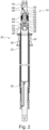
- the Kelly rod 20 is designed as a telescoping Kelly rod 20 with a tubular outer Kelly rod 22 and a tubular inner Kelly rod 24 arranged therein in a rotationally fixed but axially displaceable manner relative to the outer Kelly rod 22 .
- a tubular connection area 26 for connection to a cable swivel 40 is arranged.
- the rope swivel 40 is connected to a support rope, not shown, via which the Kelly bar 20 is held.
- a rotary feedthrough 30 is attached to a support plate, not shown.
- the kelly bar 20 is held in a vertical orientation on a mast via the suspension cable, for example when used on a drilling device, via the cable swivel 40, the kelly bar 20 being rotationally driven by an annular rotary drive for carrying out a kelly drilling method.
- the Kelly bar 20 can be placed on the rotary drive by means of an attachment ring 28 on the outer Kelly bar 22 .
- the cable swivel 40 prevents, in a manner known in principle, that the rotation of the rotary-driven Kelly bar 20 is transmitted to the carrying cable of the drilling device, which is non-rotatable for this purpose.
- the rope swivel 40 has a tubular first swivel part 41 with a sleeve body 42 . At its upper end, which faces away from the Kelly bar 20, this first swivel part 41 is fastened in a known manner by a transversely directed retaining bolt 44 to a suspension of the carrying cable.
- a rotary bearing 48 is arranged inside the sleeve body 42, with which a tubular second vortex part 50 can be rotated within the first vortex part 41, but is axially fixed is stored.
- the second swivel part 50 has a tubular outer sleeve 52 which protrudes axially in relation to the first swivel part 41 in the direction of the component to be attached, that is to say the Kelly rod 20 in the exemplary embodiment shown.
- the protruding connection end 53 of the second vertebral part 50 that is formed in this way can be plugged into the sleeve-shaped connection area 26 of the Kelly bar 20, as illustrated in FIG 1 is shown.
- the connecting end 53 of the cable swivel 40 is axially fixed and non-rotatably connected to the Kelly bar 20 via transversely directed connecting elements 18 .
- the connecting mandrel 60 has a tubular body 62 with a tubular interior 63 .
- the tubular body 62 is connected in a rotationally fixed manner to the first vortex part 41 and opens into a feed channel 46 in the first vortex part 41.
- a connection section 64 with an enlarged diameter compared to the tubular body 62 is formed , as vividly in 2 is shown.
- a counter-connecting section 36 is provided on the rotary feedthrough 30 on the Kelly bar 20, which in 3 is shown in more detail.
- the mating connection section 36 is connected in a torque-proof manner to a stator of the rotary feedthrough 30 .
- the stator can be rotated with respect to a rotor 32 of the rotary feedthrough 30 , the rotor 32 being connected to the inner kelly rod 24 in a rotationally fixed and axially fixed manner via a support plate 29 .
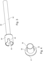
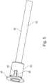
- FIGS Figures 3 to 5 The mating of the connecting section 64 on the connecting mandrel 60 with the counter-connecting section 36 on the rotary feedthrough 30 is again closer in FIGS Figures 3 to 5 shown.
- a sleeve-shaped connecting section 64 with a larger diameter is formed on the tubular body 62 of the connecting mandrel 60 at the free end.
- two groove-like recesses 65 are introduced in the axial direction on the free end face of the connecting section 64 .
- two tongue-shaped webs 38 are formed on an outer side of the sleeve-shaped mating connection section 36, which can be pushed axially into the corresponding recesses 65, with a non-rotatable form-fitting connection being formed.
- a connecting flange 37 is provided for fastening the sleeve-shaped mating connection section 36 to the rotary leadthrough 30 .
Description
Die Erfindung betrifft einen Seilwirbel zum Verbinden eines Seils oder einer Halterung mit einer relativ zum Seil beziehungsweise der Halterung drehbaren Komponente, insbesondere einer Kellystange, mit einem stehenden ersten Wirbelteil, welches an dem Seil beziehungsweise der Halterung befestigbar ist, und einem drehbaren zweiten Wirbelteil, welches an dem stehenden ersten Wirbelteil drehbar und axial fest gelagert sowie mit der Komponente verbindbar ist, gemäß dem Oberbegriff des Anspruchs 1.The invention relates to a rope swivel for connecting a rope or a bracket to a component that can be rotated relative to the rope or the bracket, in particular a Kelly bar, with a stationary first swivel part that can be attached to the rope or the bracket, and a rotatable second swivel part that rotatable and axially fixed on the standing first vertebral part and can be connected to the component, according to the preamble of claim 1.
Sogenannte Seilwirbel werden insbesondere an Baumaschinen eingesetzt, wenn an einem Tragseil oder einer Tragstange eine drehend angetriebene Komponente aufzuhängen ist, wobei sich die Drehung der Komponente nicht auf das Seil oder die Tragstange übertragen soll.So-called rope swivels are used in particular on construction machinery when a rotationally driven component is to be suspended from a suspension cable or a suspension rod, and the rotation of the component should not be transmitted to the cable or the suspension rod.
Ein Seilwirbel ist beispielsweise aus der
Weiterhin ist eine Kellystange bekannt, bei welcher unterhalb einer Seilaufhängung eine Drehdurchführung angeordnet ist. Bei dieser Anordnung wird ein Kraftfluss um die Drehdurchführung herum erreicht, so dass diese besonders schonend und damit wartungsarm betrieben werden kann.Furthermore, a Kelly bar is known in which a rotary bushing is arranged below a cable suspension. In this arrangement, a power flow is to reaches the rotary union so that it can be operated particularly gently and therefore with little maintenance.
Der Erfindung liegt die Aufgabe zugrunde, einen Seilwirbel anzugeben, mit welchem neben einer drehbaren Aufhängung einer Komponente zugleich eine zusätzliche drehfeste Verbindung geschaffen werden kann.The invention is based on the object of specifying a cable swivel with which, in addition to a rotatable suspension of a component, an additional non-rotatable connection can be created at the same time.
Die Aufgabe wird durch einen Seilwirbel mit den Merkmalen des Anspruchs 1 gelöst. Bevorzugte Ausführungsformen der Erfindung sind in den abhängigen Ansprüchen angegeben.The object is achieved by a cable swivel with the features of claim 1. Preferred embodiments of the invention are given in the dependent claims.
Der erfindungsgemäße Seilwirbel ist dadurch gekennzeichnet, dass der drehbare zweite Wirbelteil hülsenförmig mit einem axialen Durchgang ausgebildet ist und dass an dem stehenden ersten Wirbelteil oder der drehbaren Komponente ein Verbindungsdorn ausgebildet ist, welcher sich zumindest teilweise axial entlang des Durchgangs des drehbaren zweiten Wirbelteils erstreckt.The cable swivel according to the invention is characterized in that the rotatable second swivel part is sleeve-shaped with an axial passage and that a connecting mandrel is formed on the stationary first swivel part or the rotatable component, which at least partially extends axially along the passage of the rotatable second swivel part.
Eine Grundidee der Erfindung besteht darin, einen Seilwirbel mit einem hülsenförmigen drehbaren Wirbelteil auszugestalten, welcher mit der anzuhängenden drehbaren Komponente drehfest verbunden wird. Das zweite drehbare Wirbelteil ist dabei drehbar an dem feststehenden ersten Wirbelteil gelagert, welches mit dem Seil oder der feststehenden Halterung, etwa einem Kranhaken oder einer Tragstange, verbunden ist. Die hülsenförmige Gestaltung des drehbaren zweiten Wirbelteils ermöglicht es, in dem hierdurch gebildeten Durchgang einen Verbindungsdorn anzuordnen, welcher fest mit dem feststehenden ersten Wirbelteil verbunden oder drehfest verbindbar ist. Der Verbindungsdorn kann entweder fest an dem ersten Wirbelteil oder an der anzuhängenden Komponente angeordnet sein, welche eine Drehdurchführung aufweisen kann.A basic idea of the invention consists in configuring a cable swivel with a sleeve-shaped rotatable swivel part which is non-rotatably connected to the rotatable component to be attached. The second rotatable swivel part is rotatably mounted on the fixed first swivel part, which is connected to the cable or the fixed mount, such as a crane hook or a carrying rod. The sleeve-like design of the rotatable second vertebral part makes it possible to arrange a connecting mandrel in the passage formed thereby, which is firmly connected to the stationary first vertebral part or can be connected in a rotationally fixed manner. The connecting mandrel can either be arranged fixedly on the first vertebral part or on the component to be attached, which can have a rotary feedthrough.
Mit der Erfindung wird ermöglicht, neben der eigentlichen drehbaren Aufhängung einer Komponente an einem Seilwirbel gleichzeitig auch eine drehfeste Verbindung zu einer Teilkomponente, etwa einer Drehdurchführung, möglichst ohne Verschraubung von Leitungen, an der aufzuhängenden Komponente vorzusehen.The invention makes it possible, in addition to the actual rotatable suspension of a component on a cable swivel, to also provide a non-rotatable connection to a subcomponent, such as a rotary feedthrough, if possible without screwing lines to the component to be suspended.
Eine bevorzugte Ausführungsform der Erfindung besteht darin, dass der Verbindungsdorn rohrförmig ausgebildet ist und entlang seines Rohrinnenraums eine Fluidleitung, eine Datenleitung, eine elektrische Stromleitung und/oder eine Hydraulikleitung verläuft. Auf diese Weise kann der Seilwirbel nicht nur als ein einfaches Gelenkelement zur Aufhängung verwendet werden. Vielmehr wird es durch den rohrförmigen Verbindungsdorn ermöglicht, eine Flüssigkeit, ein Gas, elektrischen Strom, Daten und/oder ein sonstiges Medium unmittelbar durch den Seilwirbel zu übertragen.A preferred embodiment of the invention is that the connecting mandrel is tubular and has a fluid line along its tubular interior, a data line, an electrical power line and/or a hydraulic line runs. In this way, the cable swivel can not only be used as a simple joint element for suspension. Rather, the tubular connecting mandrel makes it possible to transmit a liquid, a gas, electrical current, data and/or another medium directly through the cable swivel.
Besonders vorteilhaft ist es nach einer Weiterbildung der Erfindung, dass an dem freien Ende des Verbindungsdorns ein Verbindungsabschnitt zum Bilden einer form-und/oder kraftschlüssigen Verbindung mit einem Gegen-Verbindungsabschnitt ausgebildet ist. Der Gegen-Verbindungsabschnitt kann passend an der anzubringenden Komponente vorgesehen sein. Der Verbindungsabschnitt kann insbesondere ein Stecker sein, welcher durch einfaches axiales Zusammenstecken eine gewünschte Verbindung zu dem Gegen-Verbindungsabschnitt herstellt. Die Verbindung kann dabei eine rein mechanische und/oder eine leitungstechnische Verbindung sein.According to a development of the invention, it is particularly advantageous that a connection section for forming a positive and/or non-positive connection with a counter-connection section is formed on the free end of the connecting mandrel. The mating connection portion may be fitted to the component to be attached. The connection section can in particular be a plug, which produces a desired connection to the counter-connection section by simply plugging it together axially. The connection can be a purely mechanical connection and/or a wiring connection.
Besonders vorteilhaft ist es nach einer Weiterbildung der Erfindung, dass der Verbindungsabschnitt mit einem Stator einer Drehdurchführung verbindbar ist. Die Drehdurchführung kann dabei an der anzubringenden Komponente vorgesehen sein. Der anzubringende Stator ist somit drehfest mit dem ersten Wirbelteil des Seilwirbels verbunden. Vorzugsweise kann dabei der Seilwirbel an einem Seil aufgehängt sein, welches im Wesentlichen drehsteif ist.According to a development of the invention, it is particularly advantageous that the connecting section can be connected to a stator of a rotary feedthrough. The rotary feedthrough can be provided on the component to be attached. The stator to be attached is thus non-rotatably connected to the first swivel part of the rope swivel. In this case, the cable swivel can preferably be suspended from a cable which is essentially torsionally rigid.
Besonders zweckmäßig ist es nach einer weiteren Ausführungsform der Erfindung, dass der Verbindungsdorn an seinem dem Durchgang abgewandten Ende einen Anschluss für eine Zuführleitung aufweist. Der Anschluss kann dabei insbesondere an einer Außenseite des ersten Wirbelteils ausgebildet sein. An dem zu der drehend antreibbaren Komponente feststehenden ersten Wirbelteil kann so eine Fluid-, elektrische Strom- oder Datenleitung entsprechend dem Tragseil oder der Tragstange angeschlossen werden. Hierdurch ist eine besonders effiziente Übertragung eines Fluides, von elektrischem Strom oder von Daten möglich.According to a further embodiment of the invention, it is particularly expedient for the connecting mandrel to have a connection for a feed line at its end remote from the passage. The connection can be formed in particular on an outside of the first vertebral part. A fluid, electrical power or data line corresponding to the support cable or the support rod can thus be connected to the first swivel part which is stationary relative to the rotationally drivable component. This enables a particularly efficient transmission of a fluid, of electrical power or of data.
Die Erfindung umfasst weiterhin eine Kellystangenanordnung mit einem solchen erfindungsgemäßen Seilwirbel und einer Kellystange, welche an ihrem oberen Ende mit dem Seilwirbel zum Anhängen an ein Tragseil und an ihrem unteren Ende mit einer Verbindungseinrichtung für ein Werkzeug, insbesondere ein Bohrwerkzeug, versehen ist. Die Kellystange kann dabei eine Einfachkellystange oder eine teleskopierbare Kellystange sein. An der Außenseite der drehbar aufgehängten Kellystange sind in grundsätzlich bekannter Weise axial verlaufende Antriebsleisten angeordnet, welche eine Drehmomentübertragung von einem ringförmigen Kellyantrieb auf die axial hierzu verschiebbare Kellystange ermöglichen.The invention also includes a Kelly bar arrangement with such a cable swivel according to the invention and a Kelly bar, which is equipped at its upper end with the cable swivel for attachment to a carrying cable and at its lower end with a connecting device for a tool, in particular a drilling tool. is provided. The Kelly bar can be a single Kelly bar or a telescopic Kelly bar. On the outside of the rotatably suspended Kelly bar, axially running drive rails are arranged in a basically known manner, which allow torque to be transmitted from an annular Kelly drive to the Kelly bar, which can be displaced axially with respect to this.
Eine bevorzugte Ausführungsform der erfindungsgemäßen Kellystangenanordnung besteht darin, dass die Kellystange drehfest mit dem drehbaren zweiten Wirbelteil verbunden ist. Das zweite Wirbelteil dreht sich somit mit der Kellystange, wenn diese drehend angetrieben wird. Der axiale Kraftfluss des Seilwirbels läuft dabei von dem Tragseil über das hierzu feststehende erste Wirbelteil auf das daran drehbar gelagerte zweite Wirbelteil, welches drehfest mit einer Aufhängeeinrichtung der Kellystange verbunden ist.A preferred embodiment of the Kelly bar arrangement according to the invention consists in the Kelly bar being connected in a rotationally fixed manner to the rotatable second vertebral part. The second swivel part thus rotates with the Kelly bar when it is driven in rotation. The axial flow of force of the cable swivel runs from the supporting cable via the first swivel part, which is fixed for this purpose, to the second swivel part, which is rotatably mounted thereon and is connected in a rotationally fixed manner to a suspension device of the Kelly bar.
Eine besonders vorteilhafte Kellystangenanordnung ergibt sich nach einer Weiterbildung der Erfindung dadurch, dass die Kellystange an ihrem oberen Ende eine Drehdurchführung aufweist, welche einen Stator und einen Rotor umfasst, welcher drehfest und axial fest mit der Kellystange verbunden ist, und dass der Stator der Drehdurchführung drehfest und lösbar mit dem Verbindungsdorn des Seilwirbels verbunden ist. Der Verbindungsdorn des Seilwirbels kann somit eine Zuführung für ein Fluid, elektrischen Strom oder von Daten von einer von außen zugeführten Zuführleitung haben, welche vorzugsweise zumindest teilweise parallel zu dem Tragseil verläuft. Der Begriff des Stators bezieht sich dabei auf das feststehende Teil der Drehdurchführung relativ zu dem Verbindungsdorn und dem ersten Wirbelteil des Seilwirbels. Der Rotor der Drehdurchführung hingegen ist im Sinne der Erfindung das Teil der Drehdurchführung, welches drehfest mit der drehend antreibbaren Kellystange verbunden ist.According to a development of the invention, a particularly advantageous Kelly bar arrangement results from the fact that the Kelly bar has a rotary feedthrough at its upper end, which includes a stator and a rotor, which is non-rotatably and axially firmly connected to the Kelly rod, and that the stator of the rotary feedthrough is non-rotatable and is detachably connected to the connecting mandrel of the cable swivel. The connecting mandrel of the cable swivel can thus have a supply for a fluid, electric power or data from a supply line supplied from the outside, which preferably runs at least partially parallel to the suspension cable. The term stator refers to the fixed part of the rotary feedthrough relative to the connecting mandrel and the first swivel part of the rope swivel. The rotor of the rotary feedthrough, on the other hand, is the part of the rotary feedthrough within the meaning of the invention that is connected in a rotationally fixed manner to the Kelly rod that can be driven in rotation.
Zum einfachen Bilden einer Leitungsverbindung ist es nach einer Ausführungsform der Erfindung vorteilhaft, dass an dem Stator ein Gegenverbindungsabschnitt angeordnet ist, welcher passend zu dem Verbindungsabschnitt an dem Verbindungsdorn ausgebildet ist. Dabei kann die Leitungsverbindung insbesondere durch ein einfaches axiales Zusammenstecken entsprechend einer Steckverbindung gebildet werden. Von einer zusätzlichen Lagesicherung, etwa einer Verschraubung oder Verbolzung, kann abgesehen werden.In order to easily form a line connection, it is advantageous according to one embodiment of the invention that a mating connection section is arranged on the stator, which is designed to match the connection section on the connection mandrel. In this case, the line connection can be formed, in particular, by simply plugging them together axially in accordance with a plug-in connection. An additional position securing, such as a screw connection or bolting, can be dispensed with.
Besonders zweckmäßig ist es dabei, dass die Leitungsverbindung als eine lösbare form- und/oder kraftschlüssige Verbindung zum Leiten eines Fluides, von Daten und/oder von elektrischem Strom ausgebildet ist. Entsprechend herkömmlichen axialen Steckverbindungen können an den Steckelementen zueinander passende Kraftschlusselemente, etwa Federn oder Spannbügel, und/oder Formschlusselemente, etwa Keilnutelemente, ausgebildet sein. Auch können zur Herstellung einer drehfesten axialen Steckverbindung die Stecker in einer unrunden Form, etwa mit einem polygonalen Querschnitt oder mit einem ovalen Querschnitt, ausgebildet sein. Zum Leiten eines Fluides sind entsprechende Kanäle vorgesehen, während zum Leiten von elektrischem Strom oder Daten entsprechende Leitungen etwa mit schleifenden Kontaktverbindungen vorgesehen sind.It is particularly expedient here that the line connection is designed as a detachable positive and/or non-positive connection for conducting a fluid, data and/or electric power. Corresponding to conventional axial plug-in connections, force-fitting elements that match one another, such as springs or clamps, and/or positive-locking elements, such as keyway elements, can be formed on the plug-in elements. To produce a non-rotatable axial plug-in connection, the plugs can also be designed in a non-round shape, for example with a polygonal cross section or with an oval cross section. Corresponding channels are provided for conducting a fluid, while corresponding lines, for example with sliding contact connections, are provided for conducting electrical current or data.
Die Erfindung umfasst weiter ein Bohrgerät zum Bohren im Boden, mit einer Trägereinheit und einem Bohrantrieb zum drehenden Antreiben einer Kellystange mit einem Bohrwerkzeug, wobei eine erfindungsgemäße Kellystangenanordnung vorgesehen ist. Die Kellystangenanordnung kann dabei so ausgebildet sein, wie sie vorausgehend beschrieben wurde. Es können somit mit dem Bohrgerät die entsprechenden Vorteile erzielt werden.The invention further includes a drilling device for drilling in the ground, with a carrier unit and a drilling drive for rotating a Kelly bar with a drilling tool, wherein a Kelly bar arrangement according to the invention is provided. The Kelly bar arrangement can be designed as previously described. The corresponding advantages can thus be achieved with the drill.
Das Bohrwerkzeug ist am unteren Ende der Kellystange angeordnet. Das Bohrwerkzeug kann insbesondere eine Bohrschnecke, ein Bohreimer, ein Verdrängungsbohrer, ein Felsbohrer oder ein sonstiges bekanntes Bohrwerkzeug für den Grundbau oder den Spezialtiefbau sein.The drilling tool is located at the lower end of the Kelly bar. The drilling tool can in particular be an auger, a drill bucket, a displacement drill, a rock drill or any other known drilling tool for foundation engineering or special civil engineering.
Die Erfindung wird nachfolgend anhand eines bevorzugten Ausführungsbeispiels weiter beschrieben, welches schematisch in den Zeichnungen dargestellt ist. In den Zeichnungen zeigen:
- Fig. 1
- eine Querschnittsansicht einer erfindungsgemäßen Kellystangenanordnung mit einem erfindungsgemäßen Seilwirbel vor einem Zusammenstecken;
- Fig. 2
- eine Querschnittsansicht einer erfindungsgemäßen Kellystangenanordnung mit einem erfindungsgemäßen Seilwirbel in einem zusammengesteckten Zustand;
- Fig. 3
- eine perspektivische Detaildarstellung eines Verbindungsdorns vor einem Verbinden;
- Fig. 4
- eine perspektivische Detaildarstellung eines Gegenverbindungsabschnitts für den Verbindungsdorns zum Verbinden; und
- Fig. 5
- eine Darstellung des Verbindungsdorns von
Fig. 2 nach dem Verbinden mit dem Gegenverbindungsabschnitt vonFig.3 .
- 1
- a cross-sectional view of a Kelly bar arrangement according to the invention with a cable swivel according to the invention before plugging it together;
- 2
- a cross-sectional view of a Kelly bar arrangement according to the invention with a cable swivel according to the invention in an assembled state;
- 3
- a perspective detail view of a connecting mandrel before connecting;
- 4
- a perspective detail view of a counter-connection section for the connecting mandrel for connecting; and
- figure 5
- a representation of the connecting mandrel of
2 after connecting to the mating connection portion ofFig.3 .
Eine erfindungsgemäße Kellystangenanordnung 10 mit einer Kellystange 20 und einem erfindungsgemäßen Seilwirbel 40 wird nachfolgend in Zusammenhang mit den
Die Kellystange 20 wird etwa beim Einsatz an einem Bohrgerät über den Seilwirbel 40 in einer vertikalen Ausrichtung an einem Mast über das Tragseil gehalten, wobei die Kellystange 20 von einem ringförmigen Drehantrieb zum Ausführen eines Kellybohrverfahrens drehend angetrieben wird. Dabei kann die Kellystange 20 mittels eines Aufsatzringes 28 an der Außenkellystange 22 auf den Drehantrieb aufgesetzt werden. Durch den Seilwirbel 40 wird in grundsätzlich bekannter Weise verhindert, dass sich die Drehung der drehend angetriebenen Kellystange 20 auf das hierzu drehfeste Tragseil des Bohrgerätes überträgt.The
Der erfindungsgemäße Seilwirbel 40 weist ein rohrförmiges erstes Wirbelteil 41 mit einem Hülsenkörper 42 auf. Dieses erste Wirbelteil 41 wird an seinem oberen Ende, welches von der Kellystange 20 abgewandt ist, in bekannter Weise durch einen quer gerichteten Haltebolzen 44 an einer Aufhängung des Tragseiles befestigt. Innerhalb des Hülsenkörpers 42 ist ein Drehlager 48 angeordnet, mit welchem innerhalb des ersten Wirbelteiles 41 ein rohrförmiges zweites Wirbelteil 50 drehbar, aber axial fest gelagert ist. Das zweite Wirbelteil 50 weist dabei eine rohrartige Außenhülse 52 auf, welche axial gegenüber dem ersten Wirbelteil 41 in Richtung zur anzubringenden Komponente, also im dargestellten Ausführungsbeispiel der Kellystange 20, vorsteht. Das hierdurch gebildete vorstehende Verbindungsende 53 des zweiten Wirbelteils 50 kann passend in den hülsenförmigen Verbindungsbereich 26 der Kellystange 20 eingesteckt werden, wie anschaulich in
Innerhalb des rohrförmigen zweiten Wirbelteiles 50 ist ein Durchgang 54 ausgebildet, in welchen ein rohrförmiger Verbindungsdorn 60 mittig hineinragt. Der Verbindungsdorn 60 weist einen Rohrkörper 62 mit einem Rohrinnenraum 63 auf. Der Rohrkörper 62 ist drehfest mit dem ersten Wirbelteil 41 verbunden und mündet in einen Zuführkanal 46 im ersten Wirbelteil 41. Am freien Ende des Verbindungsdorns 60, welches in dem durchmessererweiterten Verbindungsende 53 der Außenhülse 52 mündet, ist ein gegenüber dem Rohrkörper 62 durchmesservergrößerter Verbindungsabschnitt 64 ausgebildet, wie anschaulich in
Passend zu dem Verbindungsabschnitt 64 an dem Verbindungsdorn 60 ist an der Drehdurchführung 30 an der Kellystange 20 ein ebenfalls mittig angeordneter Gegenverbindungsabschnitt 36 vorgesehen, der in
Beim axialen Zusammenstecken von Kellystange 20 und Seilwirbel 40 wird der Gegenverbindungsabschnitt 36 axial in den hülsenförmigen Verbindungsabschnitt 64 des Verbindungsdorns 60 geschoben. Dabei wird eine Leitungsverbindung zwischen dem Verbindungsdorn 60 und der Drehdurchführung 30 hergestellt. Auf diese Weise kann über einen Anschluss 66 am hinteren Ende des Zuführkanals 46 eine Leitungsverbindung über die Drehdurchführung 30 zu einem Leitungskanal 25 im Inneren der Kellystange 20 hergestellt werden. In
Das Zusammenstecken des Verbindungsabschnittes 64 an den Verbindungsdorn 60 mit dem Gegenverbindungsabschnitt 36 an der Drehdurchführung 30 ist nochmals näher in den
Zur Befestigung des hülsenförmigen Gegenverbindungsabschnitts 36 an der Drehdurchführung 30 ist ein Verbindungsflansch 37 vorgesehen.A connecting
Claims (11)
- Rope swivel for connecting a rope or a holder to a component rotatable relative to the rope or the holder, in particular a kelly bar (30), comprising- a stationary first swivel part (41) which can be fastened to the rope or the holder, and- a rotatable second swivel part (50), which is rotatably and axially fixedly mounted to the stationary first swivel part (41) and is connectable to the component,
characterised in that- the rotatable second swivel part (50) is designed in the form of a sleeve with an axial passage (54), and- a connecting mandrel (60) is formed on the stationary first swivel part (41) or the rotatable component, which mandrel extends at least partially axially along the passage (54) of the rotatable second swivel part (50). - Rope swivel according to claim 1,
characterised in that
the connecting mandrel (60) is formed to be tubular and a fluid line, a data line, an electric power line and/or a hydraulic line runs along its tubular interior (63). - rope swivel according to claim 1 or 2,
characterised in that
at the free end of the connecting mandrel (60), a connecting portion (64) for forming a form-fitting and/or force-fitting connection with a counter connecting portion (36) is formed. - Rope swivel according to claim 3,
characterised in that
the connecting portion (64) is connectable to a stator of a rotary feed-through (30). - Rope swivel according to any one of claims 1 to 4,
characterised in that
the connecting mandrel (60) comprises a connector (66) for a supply line at its end facing away from the passage (54). - Kelly bar assembly, comprising- a rope swivel (40), and- a kelly bar (20) which is provided, at its upper end, with the rope swivel (40) for attachment to a suspension rope and, at its lower end, with a connecting device for a tool, in particular a drilling tool,characterised in that
the rope swivel (40) is designed according to any one of claims 1 to 5. - Kelly bar assembly according to claim 6,
characterised in that
the kelly bar (20) is connected to the rotatable second swivel part (50) in a rotationally fixed manner. - Kelly bar assembly according to claim 6 or 7,
characterised in thatthe kelly bar (20) comprises, at its upper end, a rotary feed-through (30) comprising a stator and a rotor (32), which rotor is connected to the kelly bar (20) in a rotationally and axially fixed manner, andin that the stator of the rotary feed-through (30) is connected to the connecting mandrel (60) of the rope swivel (40) in a rotationally fixed and releasable manner. - Kelly bar assembly according to claim 8,
characterised in that
for forming a line connection, a counter connecting portion (36) is arranged on the stator, which portion is formed to match the connecting portion (64) on the connecting mandrel (60). - Kelly bar assembly according to claim 9,
characterised in that
the line connection is formed as a releasable form-fitting and/or force-fitting connection for conducting a fluid, data and/or electric current. - Drilling apparatus for drilling in the ground, comprising a carrier unit and a drill drive for rotatably driving a kelly bar (20) with a drilling tool,
characterised in that
a kelly bar assembly (10) according to any one of claims 6 to 10 is provided.
Priority Applications (3)
| Application Number | Priority Date | Filing Date | Title |
|---|---|---|---|
| EP21163391.2A EP4060161B1 (en) | 2021-03-18 | 2021-03-18 | Swivel |
| PCT/EP2022/055710 WO2022194591A1 (en) | 2021-03-18 | 2022-03-07 | Cable swivel |
| CN202280017262.1A CN116940741A (en) | 2021-03-18 | 2022-03-07 | Rope rotating part |
Applications Claiming Priority (1)
| Application Number | Priority Date | Filing Date | Title |
|---|---|---|---|
| EP21163391.2A EP4060161B1 (en) | 2021-03-18 | 2021-03-18 | Swivel |
Publications (3)
| Publication Number | Publication Date |
|---|---|
| EP4060161A1 EP4060161A1 (en) | 2022-09-21 |
| EP4060161C0 EP4060161C0 (en) | 2023-06-28 |
| EP4060161B1 true EP4060161B1 (en) | 2023-06-28 |
Family
ID=75108183
Family Applications (1)
| Application Number | Title | Priority Date | Filing Date |
|---|---|---|---|
| EP21163391.2A Active EP4060161B1 (en) | 2021-03-18 | 2021-03-18 | Swivel |
Country Status (3)
| Country | Link |
|---|---|
| EP (1) | EP4060161B1 (en) |
| CN (1) | CN116940741A (en) |
| WO (1) | WO2022194591A1 (en) |
Family Cites Families (3)
| Publication number | Priority date | Publication date | Assignee | Title |
|---|---|---|---|---|
| DE4333114C1 (en) * | 1993-09-29 | 1994-10-13 | Klemm Bohrtech | Drilling apparatus with telescopic kelly bar |
| EP2821585B1 (en) | 2013-07-03 | 2016-01-20 | Bauer Spezialtiefbau GmbH | Drilling device and drilling method |
| EP3779117A1 (en) * | 2019-08-16 | 2021-02-17 | BAUER Maschinen GmbH | Kelly bar assembly for a drill and method for working soil |
-
2021
- 2021-03-18 EP EP21163391.2A patent/EP4060161B1/en active Active
-
2022
- 2022-03-07 CN CN202280017262.1A patent/CN116940741A/en active Pending
- 2022-03-07 WO PCT/EP2022/055710 patent/WO2022194591A1/en active Application Filing
Also Published As
| Publication number | Publication date |
|---|---|
| EP4060161C0 (en) | 2023-06-28 |
| CN116940741A (en) | 2023-10-24 |
| WO2022194591A1 (en) | 2022-09-22 |
| EP4060161A1 (en) | 2022-09-21 |
Similar Documents
| Publication | Publication Date | Title |
|---|---|---|
| DE60219033T2 (en) | SPÜLROHRANORDNUNG | |
| EP2048321B1 (en) | Drill and method for operating a drill | |
| EP3877624B1 (en) | Kelly bar assembly for a drill and method for working soil | |
| EP2561145A2 (en) | Rotary device for an attachment on a machine | |
| EP2495389A1 (en) | Drilling rod | |
| DE2545096A1 (en) | DRILLING SYSTEM OR DRILLING FRAME, IN PARTICULAR MOBILE (S), SELF-PROPELLED (S) DRILLING RIG, OR DRILLING FRAME WITH A TRANSPORTABLE, TELESCOPIC SLIDING MAST | |
| EP2113632B1 (en) | Attachment device for forming a fluid supply | |
| EP2821585B1 (en) | Drilling device and drilling method | |
| DE1239642B (en) | Extension drill | |
| EP4060161B1 (en) | Swivel | |
| EP2737159B1 (en) | Holder for tubular drilling tools having different diameters | |
| DE4014752C2 (en) | Longitudinal cutting arm for tunneling and mining purposes u. the like | |
| EP1123784A2 (en) | Tool adapter on a robotic interface | |
| EP2765271B1 (en) | Drilling table | |
| DE19621849C2 (en) | Device for rotating and axially moving drill pipe strings | |
| DE1634950B2 (en) | EXCAVATOR GRAPPLE | |
| EP3699390B1 (en) | Earth boring device, system comprising the earth boring device, method for manufacturing an earth boring device and use of an earth boring device | |
| EP0518114B1 (en) | Device for releasably connecting a drill pipe to a rotary drive | |
| EP3882398B1 (en) | Drilling rod and method for retrofitting a kelly bar assembly | |
| DE10024724C2 (en) | Connector for a drill for drilling holes in bone tissue and drill | |
| AT523416B1 (en) | Device for data and / or power transmission on a derrick or a treatment winch | |
| EP3862528B1 (en) | Down hole drilling rig and method for producing a borehole | |
| DE202006006117U1 (en) | Rotation actuator, has interface part and output part aligned together such that interface part is positionable in output part by successive linear displacement, where axial locking engagement is provided between output and interface parts | |
| EP4033067A1 (en) | Rotating drive assembly for a drilling rod | |
| WO2002070858A2 (en) | Drilling device comprising a rotational drive |
Legal Events
| Date | Code | Title | Description |
|---|---|---|---|
| PUAI | Public reference made under article 153(3) epc to a published international application that has entered the european phase |
Free format text: ORIGINAL CODE: 0009012 |
|
| STAA | Information on the status of an ep patent application or granted ep patent |
Free format text: STATUS: REQUEST FOR EXAMINATION WAS MADE |
|
| 17P | Request for examination filed |
Effective date: 20210908 |
|
| AK | Designated contracting states |
Kind code of ref document: A1 Designated state(s): AL AT BE BG CH CY CZ DE DK EE ES FI FR GB GR HR HU IE IS IT LI LT LU LV MC MK MT NL NO PL PT RO RS SE SI SK SM TR |
|
| GRAP | Despatch of communication of intention to grant a patent |
Free format text: ORIGINAL CODE: EPIDOSNIGR1 |
|
| STAA | Information on the status of an ep patent application or granted ep patent |
Free format text: STATUS: GRANT OF PATENT IS INTENDED |
|
| INTG | Intention to grant announced |
Effective date: 20230127 |
|
| GRAS | Grant fee paid |
Free format text: ORIGINAL CODE: EPIDOSNIGR3 |
|
| GRAA | (expected) grant |
Free format text: ORIGINAL CODE: 0009210 |
|
| STAA | Information on the status of an ep patent application or granted ep patent |
Free format text: STATUS: THE PATENT HAS BEEN GRANTED |
|
| AK | Designated contracting states |
Kind code of ref document: B1 Designated state(s): AL AT BE BG CH CY CZ DE DK EE ES FI FR GB GR HR HU IE IS IT LI LT LU LV MC MK MT NL NO PL PT RO RS SE SI SK SM TR |
|
| REG | Reference to a national code |
Ref country code: CH Ref legal event code: EP |
|
| REG | Reference to a national code |
Ref country code: AT Ref legal event code: REF Ref document number: 1582824 Country of ref document: AT Kind code of ref document: T Effective date: 20230715 |
|
| REG | Reference to a national code |
Ref country code: IE Ref legal event code: FG4D Free format text: LANGUAGE OF EP DOCUMENT: GERMAN |
|
| REG | Reference to a national code |
Ref country code: DE Ref legal event code: R096 Ref document number: 502021000914 Country of ref document: DE |
|
| U01 | Request for unitary effect filed |
Effective date: 20230719 |
|
| U07 | Unitary effect registered |
Designated state(s): AT BE BG DE DK EE FI FR IT LT LU LV MT NL PT SE SI Effective date: 20230726 |
|
| REG | Reference to a national code |
Ref country code: LT Ref legal event code: MG9D |
|
| PG25 | Lapsed in a contracting state [announced via postgrant information from national office to epo] |
Ref country code: NO Free format text: LAPSE BECAUSE OF FAILURE TO SUBMIT A TRANSLATION OF THE DESCRIPTION OR TO PAY THE FEE WITHIN THE PRESCRIBED TIME-LIMIT Effective date: 20230928 |
|
| PG25 | Lapsed in a contracting state [announced via postgrant information from national office to epo] |
Ref country code: RS Free format text: LAPSE BECAUSE OF FAILURE TO SUBMIT A TRANSLATION OF THE DESCRIPTION OR TO PAY THE FEE WITHIN THE PRESCRIBED TIME-LIMIT Effective date: 20230628 Ref country code: HR Free format text: LAPSE BECAUSE OF FAILURE TO SUBMIT A TRANSLATION OF THE DESCRIPTION OR TO PAY THE FEE WITHIN THE PRESCRIBED TIME-LIMIT Effective date: 20230628 Ref country code: GR Free format text: LAPSE BECAUSE OF FAILURE TO SUBMIT A TRANSLATION OF THE DESCRIPTION OR TO PAY THE FEE WITHIN THE PRESCRIBED TIME-LIMIT Effective date: 20230929 |
|
| PG25 | Lapsed in a contracting state [announced via postgrant information from national office to epo] |
Ref country code: SK Free format text: LAPSE BECAUSE OF FAILURE TO SUBMIT A TRANSLATION OF THE DESCRIPTION OR TO PAY THE FEE WITHIN THE PRESCRIBED TIME-LIMIT Effective date: 20230628 |
|
| PG25 | Lapsed in a contracting state [announced via postgrant information from national office to epo] |
Ref country code: ES Free format text: LAPSE BECAUSE OF FAILURE TO SUBMIT A TRANSLATION OF THE DESCRIPTION OR TO PAY THE FEE WITHIN THE PRESCRIBED TIME-LIMIT Effective date: 20230628 |
|
| PG25 | Lapsed in a contracting state [announced via postgrant information from national office to epo] |
Ref country code: IS Free format text: LAPSE BECAUSE OF FAILURE TO SUBMIT A TRANSLATION OF THE DESCRIPTION OR TO PAY THE FEE WITHIN THE PRESCRIBED TIME-LIMIT Effective date: 20231028 |
|
| PG25 | Lapsed in a contracting state [announced via postgrant information from national office to epo] |
Ref country code: SM Free format text: LAPSE BECAUSE OF FAILURE TO SUBMIT A TRANSLATION OF THE DESCRIPTION OR TO PAY THE FEE WITHIN THE PRESCRIBED TIME-LIMIT Effective date: 20230628 Ref country code: SK Free format text: LAPSE BECAUSE OF FAILURE TO SUBMIT A TRANSLATION OF THE DESCRIPTION OR TO PAY THE FEE WITHIN THE PRESCRIBED TIME-LIMIT Effective date: 20230628 Ref country code: RO Free format text: LAPSE BECAUSE OF FAILURE TO SUBMIT A TRANSLATION OF THE DESCRIPTION OR TO PAY THE FEE WITHIN THE PRESCRIBED TIME-LIMIT Effective date: 20230628 Ref country code: IS Free format text: LAPSE BECAUSE OF FAILURE TO SUBMIT A TRANSLATION OF THE DESCRIPTION OR TO PAY THE FEE WITHIN THE PRESCRIBED TIME-LIMIT Effective date: 20231028 Ref country code: ES Free format text: LAPSE BECAUSE OF FAILURE TO SUBMIT A TRANSLATION OF THE DESCRIPTION OR TO PAY THE FEE WITHIN THE PRESCRIBED TIME-LIMIT Effective date: 20230628 Ref country code: CZ Free format text: LAPSE BECAUSE OF FAILURE TO SUBMIT A TRANSLATION OF THE DESCRIPTION OR TO PAY THE FEE WITHIN THE PRESCRIBED TIME-LIMIT Effective date: 20230628 |
|
| PG25 | Lapsed in a contracting state [announced via postgrant information from national office to epo] |
Ref country code: PL Free format text: LAPSE BECAUSE OF FAILURE TO SUBMIT A TRANSLATION OF THE DESCRIPTION OR TO PAY THE FEE WITHIN THE PRESCRIBED TIME-LIMIT Effective date: 20230628 |