EP4059773A1 - Apparatus for use with a vehicle armrest - Google Patents
Apparatus for use with a vehicle armrest Download PDFInfo
- Publication number
- EP4059773A1 EP4059773A1 EP22162332.5A EP22162332A EP4059773A1 EP 4059773 A1 EP4059773 A1 EP 4059773A1 EP 22162332 A EP22162332 A EP 22162332A EP 4059773 A1 EP4059773 A1 EP 4059773A1
- Authority
- EP
- European Patent Office
- Prior art keywords
- flexible sheet
- armrest
- seatback
- tensioning means
- gap
- Prior art date
- Legal status (The legal status is an assumption and is not a legal conclusion. Google has not performed a legal analysis and makes no representation as to the accuracy of the status listed.)
- Pending
Links
Images


Classifications
-
- B—PERFORMING OPERATIONS; TRANSPORTING
- B60—VEHICLES IN GENERAL
- B60N—SEATS SPECIALLY ADAPTED FOR VEHICLES; VEHICLE PASSENGER ACCOMMODATION NOT OTHERWISE PROVIDED FOR
- B60N2/00—Seats specially adapted for vehicles; Arrangement or mounting of seats in vehicles
- B60N2/75—Arm-rests
- B60N2/753—Arm-rests movable to an inoperative position
- B60N2/757—Arm-rests movable to an inoperative position in a recess of the back-rest
-
- B—PERFORMING OPERATIONS; TRANSPORTING
- B60—VEHICLES IN GENERAL
- B60N—SEATS SPECIALLY ADAPTED FOR VEHICLES; VEHICLE PASSENGER ACCOMMODATION NOT OTHERWISE PROVIDED FOR
- B60N2/00—Seats specially adapted for vehicles; Arrangement or mounting of seats in vehicles
- B60N2/75—Arm-rests
- B60N2/763—Arm-rests adjustable
- B60N2/767—Angle adjustment
-
- B—PERFORMING OPERATIONS; TRANSPORTING
- B60—VEHICLES IN GENERAL
- B60N—SEATS SPECIALLY ADAPTED FOR VEHICLES; VEHICLE PASSENGER ACCOMMODATION NOT OTHERWISE PROVIDED FOR
- B60N2/00—Seats specially adapted for vehicles; Arrangement or mounting of seats in vehicles
- B60N2/90—Details or parts not otherwise provided for
Definitions
- the present disclosure relates to an apparatus for use with a vehicle armrest, and particularly but not exclusively to an apparatus comprising a flexible sheet for covering a gap between a vehicle armrest and an adjacent structure of the vehicle.
- aspects of the invention relate to an apparatus for use with a vehicle armrest, to a rear seat assembly comprising the apparatus for use in a vehicle, and to a vehicle comprising the apparatus or the rear seat assembly.
- a rear seat assembly is a common module of a vehicle.
- the rear seat assembly typically comprises a seat on which at least one user may sit in the vehicle.
- the rear seat assembly may include a deployable armrest, which can be provided in a stowed state in which the armrest is at least partially received in a normally substantially vertical part of the rear seat assembly, hereinafter referred to as the seatback.
- the armrest may be moved from the stowed state to a deployed state, in which the armrest extends at an angle from the seatback to provide a platform on which the user may rest an arm, for example.
- the armrest is typically connected to the seatback or elsewhere in the rear seat assembly by a hinged mechanism that enables rotation of the armrest about the hinge to rotate the armrest between the stowed and deployed states.
- the armrest may be arranged in different positions by adjusting the rotation of the armrest. For example, users may prefer different positions of the armrest depending on the size of the user.
- the seatback may be adjustable to provide a different inclination of the seatback with respect to the seat to provide a user with additional options which may provide additional comfort.
- the armrest is typically received within the seatback and forms a part of the seatback when the armrest is in the stowed position.
- a gap or void exists generally between an end of the armrest proximal to the seatback and the seatback.
- the gap or void arises due to the packaging volume required to store the armrest when it is received by the seatback in the stowed position, and the gap is larger when the volume of the armrest is greater.
- a large armrest is commonly provided in premium vehicles such as to allow for greater padding of the armrest.
- a sufficiently large void must be provided in the seatback to receive the armrest in the stowed position. This results in the gap between the armrest and the seatback when the armrest is deployed.
- the gap between the armrest and the seatback is undesirable because internal components of the seatback or of the armrest mechanism are exposed to the vehicle cabin, and thus the gap enables ingress of dirt into the seatback and the protection of internal components of the rear seat assembly is compromised.
- the gap reduces the premium appearance of the internal cabin of the vehicle, and there is a risk of belongings of the user falling into the gap and becoming trapped. Therefore, it is desirable to cover the gap between the armrest and the seatback by providing material which substantially covers the gap.
- the gap or void may change in size as the armrest and/or the seatback are moved between different positions, which increases the difficulty of covering the gap.
- the embodiments of the invention seek to provide an apparatus which can cover a gap of variable size.
- an apparatus for use in a vehicle comprising:
- a support is positioned between the first end and the tensioning means such that the flexible sheet is maintained in tension by the tensioning means over the support.
- an apparatus for use with a vehicle armrest comprising:
- the gap is of variable size.
- the flexible sheet is held under tension by the tensioning means and continues to cover the gap despite changes in the size of the gap. Due to its flexibility, both the angle and length of the flexible sheet can be changed to accommodate changes in the size of the gap.
- the adjacent structure is a seatback and, optionally, the seat back of a rear seat assembly.
- the armrest may be deployable from a stowed position where it is received within a void in the seatback to a position in which it extends from the seatback such that the flexible sheet covers a gap between an end of the armrest proximal to a seatback and the seatback itself.
- the tensioning means may comprise a tensioning mechanism.
- the tensioning mechanism may comprise a rolling spring and a roller.
- the rolling spring may resiliently engage with the roller to maintain tension on the flexible sheet to accommodate a change in the size of the gap.
- the apparatus may comprise a pair of laterally disposed frame sides arranged to support the tensioning means and the tension bar between the laterally disposed frame sides; and the laterally disposed frame sides may be configured for rotatably supporting the armrest there-between.
- the frame sides may provide support to the apparatus to maintain alignment of the apparatus and in particular the flexible sheet with the armrest.
- the tension bar may be configured to support an intermediate portion of the flexible sheet, the intermediate portion being at a position between the first and second ends of the flexible sheet, wherein the tensioned flexible sheet is arranged over the tension bar to change direction at the intermediate portion.
- the tension bar provides flexibility as to the positioning of the flexible sheet.
- the change in direction of the flexible sheet may be greater than 90 degrees. Due to the change in direction of the flexible sheet, the volume for providing the apparatus may be reduced.
- the tensioning means may be configured to maintain tension on the flexible sheet and to move the flexible sheet to continue to cover the gap during movement of the first end of the flexible sheet.
- the flexible sheet may be connectable to the armrest by a first connection element provided at the first end of the flexible sheet.
- the first connection element may enable the flexible sheet to be easily attached to or detached from the armrest. Access to the apparatus for servicing may thereby be improved, and a flexible sheet may be easily replaced.
- the apparatus may comprise a second connection element arranged to connect the flexible sheet to the tensioning means at the second end of the flexible sheet.
- the second connection element may enable the flexible sheet to be easily attached to or detached from the tensioning means. Access to the apparatus (and to the internals of the seatback in use) for servicing may thereby be improved, and a flexible sheet may be easily replaced.
- the flexible sheet may have a length greater than a maximum size of the gap.
- the flexible sheet may continue to cover the gap when the gap is adjusted to any potential size.
- the flexible sheet may accommodate an increase in distance between the two fixing points of the flexible sheet when the armrest is stowed.
- a rear seat assembly for use in a vehicle, the rear seat assembly comprising:
- the gap to be covered by the flexible sheet in use is located between an end of the armrest proximal to the seatback and the seatback.
- the gap may be of variable size.
- the flexible sheet may cover a gap between the armrest and the seatback and prevent ingress of dirt into the seatback and damage of internal components of the seatback.
- the rear seating assembly may comprise laterally disposed frame sides arranged to support the flexible sheet, the tensioning means and the tension bar between the laterally disposed frame sides, to hingeably support the armrest, and to connect the armrest to the seatback.
- the frame sides may support said elements to maintain alignment so that the flexible sheet can reliably cover the gap between the armrest and the seatback.
- the armrest may be attached between the laterally disposed frame sides and configured to rotate about an axis perpendicular to the laterally disposed frame sides.
- the alignment of the flexible sheet with the gap between the armrest and the seatback is improved.
- the tensioning means may be substantially located within the seatback.
- the tensioning means may be protected from the ingress of dirt or from potential sources of damage. Additionally, the tensioning means may be hidden from view in use and a comfort level of the vehicle may be improved.
- the tensioning means may be configured to maintain tension on the flexible sheet to continue to cover the gap when the size of the gap between the armrest and the seatback varies as the armrest rotates between the stowed position and the deployed position.
- the gap between the armrest and the seatback may be covered by the flexible sheet even when the armrest is positioned at different positions by a user. Therefore, different user preferences can be accommodated without compromising on the level of cover of the gap.
- the seatback may be configured to be movable, wherein the size of the gap between the armrest and the seatback changes during movement of the seatback, and the tensioning means may be configured to maintain tension on the flexible sheet to continue to cover the gap when the size of the gap between the armrest and the seatback changes during movement of the seatback.
- the gap may continue to be covered when users move the seatback, for example to accommodate different user preferences or sizes.
- the tension bar may be located in the seatback and may be at least partially obscured by the seatback.
- the tension bar and a portion of the flexible sheet provided between the tension bar and the tensioning means may be protected from damage by the seatback, and a premium appearance of the vehicle cabin may be improved by obscuring the tension bar.
- the rear seat assembly may comprise a shielding element provided to overlap with one or more lateral edges of the flexible sheet to partially obscure the flexible sheet.
- the coverage of the gap by the flexible sheet is improved as the shielding element provides cover to accommodate any height difference between the flexible sheet and the gap.
- a first portion of the flexible sheet between the tension bar and the armrest may be held under tension to cover the gap.
- a second portion of the flexible sheet between the tension bar and the tensioning means may be located within the seatback and may be at least partially obscured by the seatback.
- the tensioning means may be configured to maintain tension on the flexible sheet and to adjust the sizes of the first portion and the second portion of the flexible sheet when the size of the gap changes in response to movement of the armrest or the seatback.
- the gap may be covered by the first portion of the flexible sheet while the second portion of the flexible sheet may be protected inside the seatback.
- the relative sizes of the first and second portions of the flexible sheet may be automatically adjusted by the tensioning means in response to movement of the armrest or the seatback to continue to cover the gap when the size of the gap is changed.
- the tensioning means may comprise a rolling spring and a roller
- the rolling spring may be arranged to resiliently wrap around the roller and may be connected between the second end of the flexible sheet and the roller.
- the relative sizes of the first and second portions of the flexible sheet may be adjusted by winding or unwinding the rolling spring around the roller to move the flexible sheet and to control the length of the flexible sheet located on either side of the tension bar.
- the rolling spring automatically adjusts position to change the length of the flexible sheet provided to cover the gap as the gap changes size.
- the rolling spring when the armrest is in the stowed position, the rolling spring is wound around the roller by a first amount, and when the armrest is in the deployed position, the rolling spring is wound around the roller by a second amount, the second amount being greater than the first amount.
- the flexible sheet is automatically moved by the winding or unwinding of the rolling spring as the armrest is moved between the stowed and deployed states.
- a vehicle comprising the apparatus and/or the rear seat assembly described above.
- FIG. 1a shows a representation of the apparatus 10 in accordance with an embodiment of the present invention, where the apparatus 10 is in a stowed position.
- the apparatus 10 comprises a flexible sheet 11, a tension bar 12, tensioning means 13, a first connection element 16 and a second connection element 17.
- the tensioning mean is a tensioning mechanism arranged to apply tension to the flexible sheet 11.
- the tensioning means 13 of Figure 1a comprises a rolling spring 14 and a roller 15 about which the rolling spring 14 is configured to resiliently wrap.
- the tensioning means 13 may be any tensioning mechanism which can be coupled to the flexible sheet 11 via the second connection element 17 and which can maintain tension on the flexible sheet 11.
- the flexible sheet 11 is an elongate sheet of flexible material.
- the flexible sheet 11 is connected to the first connection element 16 at a first end of the flexible sheet 11 and is connected to the second connection element 17 at a second end of the flexible sheet 11.
- the second connection element 17 is also connected to the tensioning means 13.
- the tension bar 12 is provided along the length of the flexible sheet 11 to support the flexible sheet 11 between the first end and the second end of the flexible sheet 11.
- the flexible sheet 11 is connectable to an armrest of a vehicle at a first end of the flexible sheet 11 by the first connection element 16. While the flexible sheet 11 is described to be connectable between to armrest of a vehicle, this is only an example, and the apparatus 10 and flexible sheet 11 may be connectable between any two structures of a vehicle.
- the apparatus 10 including the flexible sheet 11 may be used to cover a gap existing between a seatback and base of a seat. That is, the apparatus 10 may be used to cover any gap between two structures existing inside of a vehicle, and is particularly advantageous where the gap between the two structures is of variable size due to movement of one or more of the two structures.
- the first connection element 16 of the apparatus 10 of Figure 1a may be a connection clip.
- the first connection element 16 may have a shape that enables the first connection element 16 to engage with a corresponding part of an armrest to secure the flexible sheet 11 to the armrest.
- the shape of the first connection element 16 shown in Figure 1a is only an example, and the shape of the first connection element 16 may be any suitable shape for connecting securely to an armrest of a vehicle.
- the flexible sheet 11 may be formed of any flexible material.
- the flexible sheet 11 may be formed of leather, fabric polyvinyl chloride (PVC), a plastic material, or any other flexible material.
- the flexible sheet 11 may be formed of a material which matches a material used in the interior cabin of the vehicle, and particularly which is used for construction of a rear seat assembly provided in the rear of the vehicle.
- the flexible sheet 11 is flexible, as opposed to rigid.
- the flexible sheet 11 is sufficiently flexible to be deformable under the effects of gravity, and to be able to be held taut by the tensioning means 13.
- the flexible sheet 11 is sufficiently flexible to bend at the position of the tension bar 12 and to change direction by greater than 90 degrees.
- Figure 1a shows a side profile of the apparatus 10.
- the flexible sheet 11 and the other components of the apparatus 10 may also have a width as shown in Figures 2a and 2b . That is, the flexible sheet 11 of Figure 1a may be considered substantially rectangular in shape. However, the shape of the flexible sheet 11 may be different depending on the construction of the armrest and the seatback, and the corresponding shape and size of the gap to be covered.
- the tension bar 12 of Figure 1a is configured to provide support to the flexible sheet 11 at a position between the first end and the second end of the flexible sheet 11.
- the tension bar 12 may be a cylindrical or similarly shaped element, which is securely fixable within the seatback of the vehicle in use.
- the tension bar 12 may be formed of different shapes.
- the tension bar 12 may be formed of one or more separate elements which may be attached in use to the inside of the seatback.
- these may be elements extending from a frame provided inside the seatback which are configured to support the flexible sheet 11.
- the tension bar 12 is securely fixed in use such that when the tensioning means 13 apply tension to the flexible sheet 11, the tension bar 12 is fixed and does not move in response to pressure from the flexible sheet 11.
- the tension bar 12 is configured to provide support to the flexible sheet 11 at a position between the first and second ends of the flexible sheet 11.
- the tension bar 12 may be positioned such that the flexible sheet 11 changes direction where the flexible sheet 11 is supported by the tension bar 12.
- the change in direction of the flexible sheet 11 where supported by the tension bar 12 is shown as being an angle greater than 90 degrees.
- the invention is not limited to this example, and the tension bar 12 may enable any change in direction of the flexible sheet 11.
- the change in direction of the flexible sheet 11 where supported by the tension bar 12 enables a reduced volume required for providing the apparatus 10.
- the tensioning means 13 and a portion of the flexible sheet 11 between the tension bar 12 and the second connection element 17 can be obscured in use by the seatback. This provides further protection to the tensioning means 13 and the portion of the flexible sheet 11 obscured by the seatback and improves the appearance of the interior cabin of the vehicle.
- the second connection element 17 is configured to connect the second end of the flexible sheet 11 to the tensioning means 13.
- the second connection element 17 may be any suitable connecting element for providing a connection between the flexible sheet 11 and the tensioning means 13.
- the tensioning means 13 of Figure 1a comprises a rolling spring 14 and a roller 15.
- the rolling spring 14 is configured to resiliently wrap around the roller 15.
- the rolling spring 14 is a spring which is biased to a state where the rolling spring 14 is wrapped about, or wound around, the roller 15. That is, the rolling spring 14 tends toward a position where the rolling spring 14 is fully wound around the roller 15.
- the rolling spring 14 is thereby configured to apply tension to the second end of the flexible sheet 11 to pull the second end of the flexible sheet 11 toward the tensioning means 13.
- the flexible sheet 11 is attached to an armrest via the first connection element 16 and to the tensioning means 13 via the second connection element 17.
- the tensioning means 13 maintains tension on the flexible sheet 11.
- the tensioning means 13 maintain tension on the flexible sheet 11.
- the position of the flexible sheet 11 with respect to the tension bar 12 is adjusted, such that a size of a first portion of the flexible sheet 11 between the tension bar 12 and the first end of the flexible sheet 11 and a size of a second portion of the flexible sheet 11 between the tension bar 12 and the second end of the flexible sheet 11 are adjusted by the action of the tensioning means in response to movement of the armrest to which the first connection element 16 connects the flexible sheet 11 in use.
- Figure 1b shows the apparatus 10 of Figure 1a in different state.
- Figure 1a shows the apparatus 10 in a stowed state.
- Figure 1a may be considered a representation of the apparatus 10 in a state where an armrest of a vehicle is stowed within a seatback in a rear seat assembly of the vehicle, where the first connection element 16 connects the flexible sheet 11 to the armrest in use.
- Figure 1b shows the apparatus 10 in a deployed state.
- Figure 1b may be considered a representation of the apparatus 10 in a state where the armrest of the vehicle is deployed within the seatback in the rear seat assembly of the vehicle.
- the apparatus 10 of Figure 1b is the same as the apparatus 10 of Figure 1a .
- the tensioning means 13 may be in a first state.
- the tensioning means 13 comprises a rolling spring 14 and a roller 15
- the rolling spring 14 is wrapped about the roller 15 by a first amount.
- the tensioning means 13 is in a second state.
- the rolling spring is wrapped about the roller 15 by a second amount.
- the second amount is greater than the first amount.
- the rolling spring 14 may be fully unwound, and in the second state, the rolling spring may be fully wound about the roller 15.
- the invention is not limited to the first and second states respectively corresponding to the rolling spring 14 being fully unwound and fully wound about the roller 15.
- the rolling spring 14 may provide a greater range of movement and may be partially wound in both the first and the second states.
- the first portion of the flexible sheet 11 is automatically adjusted by the tensioning means 13 to respond to changes in distance between the tensioning means 13 and the first end of the flexible sheet 11.
- the first end of the flexible sheet 11 is attached to a vehicle armrest via the first connection element 16.
- the flexible sheet 11 is moved to cover a gap existing between the armrest and the seatback. This is shown with respect to Figures 3 to 5 .
- Figures 2a and 2b show a different representation of an apparatus 10 such as the apparatus 10 of Figures 1a and 1b .
- the tension bar 12 is illustrated as being provided across the entire width of the flexible sheet 11.
- the tension bar 12 may be formed to support the flexible sheet 11 across a different proportion of the width of the flexible sheet 11.
- the second connection element 17 is a connection bar comprising a straight portion and a looped portion.
- the straight portion is attached across the width of the second end of the flexible sheet 11 and the looped portion is configured to engage with the tensioning means 13.
- the second connection element may be any shape suitable for providing a secure connection between the second end of the flexible sheet 11 and the tensioning means 13.
- Figure 2b shows an exploded view of the apparatus 10 of Figure 2a .
- the first connection element 16 is represented as a connection clip, however, the invention is not limited thereto and the first connection element 16 may be any suitable connection element for providing a connection between the first end of the flexible sheet 11 and a part of the vehicle such as the armrest in use.
- the first connection element 16 is a connection clip configured to attach across a width of the flexible sheet 11 at the first end of the flexible sheet 11.
- the first connection element 16 of Figure 2b is formed with a shape such that the first connection element 16 is attachable to an armrest of the vehicle.
- the first connection element 16 may be formed with protruding teeth which are arranged to engage in use with correspondingly shaped elements on the armrest and thereby secure the flexible sheet 11 to the armrest.
- the roller 15 of Figure 2b is shown as substantially cylindrical, but the invention is not limited thereto.
- the rolling spring 14 of Figure 2b is configured to resiliently wrap about the roller 15.
- the rolling spring 14 and the roller 15 of Figure 2b have complementary shapes.
- the apparatus 10 may comprise a pair of laterally disposed frame sides, between which the flexible sheet 11, the tension bar 12, and the tensioning means 13 may be supported.
- the laterally disposed frame sides may be provided in use inside the seatback and thus be obscured from view.
- the laterally disposed frame sides may only support certain components of the apparatus 10, and other components of the apparatus 10 may be fixed directly to an internal structure of the seatback or rear seat assembly.
- Figures 3a and 3b show a representation of an apparatus 10 according to an embodiment of the invention in use, where the apparatus 10 is connected to an armrest 20 of a vehicle.
- Figure 3a shows a representation where the armrest 20 is in the stowed state
- Figure 3b shows a representation where the armrest 20 is in the deployed state.
- the armrest 20 in the stowed state, is positioned substantially vertical, or substantially in a plane with a seatback of a seating assembly in a vehicle, such that the armrest 20 may be received by the seatback.
- the armrest 20 In the deployed state, the armrest 20 extends at an angle from the seatback.
- the armrest 20 may be deployed by a user for the user to rest on a surface 21 of the armrest 20, for example.
- the armrest 20 of Figures 3a and 3b comprises a surface 21 on which a user may rest, a connection point 22 and a support frame 23.
- the armrest 20 may be provided in a rear seat assembly in a vehicle.
- the rear seat assembly may include seating on which one or more users can sit, and a seatback providing a surface to support a user's back.
- the armrest 20 may be provided as part of the rear seat assembly in use.
- the armrest 20 may be provided in a central position in the seatback of the rear seat assembly, and therefore may be provided substantially in the middle of the interior cabin of a vehicle.
- the armrest 20 may be arranged to move between a stowed state in which the armrest 20 is at least partially received by the seatback, and a deployed state in which the armrest 20 extends from the seatback.
- the surface 21 of the armrest 20 is a portion of the armrest 20 which is provided in use to the interior of a vehicle, and may for example be provided to support a user's arm.
- the connection point 22 is configured to enable the armrest 20 to rotate relative to the seatback to move the armrest 20 between the deployed state and the stowed state.
- the connection point 22 may be a hinge or similar rotation mechanism, such that the armrest 20 is rotatable about the hinge.
- the support frame 23 of the armrest 20 is connectable in use to the seatback.
- the support frame 23 of the armrest 20 may include the pair of laterally disposed frame sides.
- the support frame 23 of the armrest 20 may be configured to support the apparatus 10 including the flexible sheet 11, the tension bar 12 and the tensioning means 13.
- the support frame 23 of the armrest 20 is fixed in use to the seatback, and may not be moveable with respect to the seatback in use.
- the apparatus 10 of Figures 1a to 2b is attached to the armrest 20 by the first connection element 17 at the first end of the flexible sheet 11.
- the tension bar 12 and tensioning means 13 are provided at an end of the armrest 20 proximal to the seatback.
- the armrest 20 is in the stowed state.
- the armrest 20 is received in use by the seatback and the flexible sheet 11 of the apparatus is packaged behind the armrest 20 (i.e., within the seatback in use).
- the flexible sheet 11 is held under tension between the armrest 20 and the tensioning means 13.
- the tension bar 12 enables a change in direction of the flexible sheet 11 which reduces the packaging volume of the apparatus 10.
- the armrest 20 is in the deployed state.
- the flexible sheet 11 is provided to cover the gap between an end of the armrest 20 proximal to the seatback and the seatback.
- the flexible sheet 11 thereby is provided to obscure the support frame 23 as well as the interior of the seatback.
- the flexible sheet 11 is held under tension between the armrest 20 and the tensioning means 13. As such, the flexible sheet 11 is positioned to cover the gap between the armrest 20 and the seatback. Internal components of the seatback are thereby protected and ingress of dirt is prevented.
- the tensioning means 13 moves to maintain tension on the flexible sheet 11.
- the tensioning means comprises the rolling spring 14 and the roller 15, and the rolling spring 14 is wound about the roller 15 as the armrest 20 moves from the stowed state to the deployed state.
- the rolling spring 14 is unwound about the roller 15.
- the movement of the rolling spring 14 changes a length of a first portion of the flexible sheet 11 provided between the tension bar 12 and the armrest 20.
- the flexible sheet 11 is moved to accommodate the change in the size of the gap between the armrest 20 and the seatback.
- the flexible sheet 11 is always held under tension by the tensioning means 13 independently of the position of the armrest 20, and therefore the flexible sheet 11 is positioned correctly and held taut to cover the gap even when the armrest 20 is moved between different positions.
- the seatback may also be movable with respect to the armrest 20.
- a user may be able to adjust the seatback to recline the seatback to personalise the seating position. This may also result in a change in the size of the gap between the armrest 20 and the seatback.
- the apparatus 10 of Figures 1 to 3 can also accommodate this change in size of the gap, because the flexible sheet 11 is always held under tension and the length of the flexible sheet 11 provided to cover the gap is adjusted by the tensioning means 13.
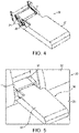
- Figure 4 shows a representation of the armrest 20 of Figure 3b , where the armrest 20 is in the deployed state.
- the flexible sheet 11 is provided to cover a gap between the armrest 20 and the seatback in use when the armrest 20 is deployed.
- the rear seat assembly comprises a shielding element 31, provided to overlap with one or more lateral edges of the flexible sheet 11 to partially obscure the flexible sheet 11.
- the shielding element 31 may be fixed within a recess in the seatback, said recess being provided to accommodate the armrest 20 in the stowed position.
- the shielding element 31 partially obscures the flexible sheet 11 to improve the coverage of the gap between the armrest 20 and the seatback.
- the shielding element 31 may accommodate for any height difference between the flexible sheet 11 and the armrest 20 due to the position of the armrest 20.
- the shielding element 31 also obscures the lateral sides of the flexible sheet 11 to obscure the interior of the seatback when the gap is viewed from a range of angles.
- FIG 5 shows a representation of a rear seat assembly 30 according to an embodiment of the invention.
- the rear seat assembly 30 comprises a seatback 32, a seat 33, an armrest 20 such as the armrest 20 of Figures 3a to 4 , and an apparatus 10 including a flexible sheet 11 such as the apparatus 10 of Figures 1a to 2b .
- the rear seat assembly 30 is for installing in the rear of a vehicle in use, to provide a seating area for passengers.
- the armrest 20 of Figure 5 is movable between a stowed state where the armrest 20 is at least partially received by the seatback 32, and a deployed state where the armrest 20 extends from the seatback 32 to be positioned over the seat 33 and to provide a surface 21 to support a user's arm, for example.
- the armrest 20 is movable between the stowed and the deployed states by rotation around an axis proximal to the seatback 32 at an end of the armrest 20.
- the axis of rotation is substantially perpendicular to the seatback 32.
- the seatback 32 includes a void for receiving the armrest 20.
- the apparatus 10 is provided to cover the gap and to protect the internal parts of the rear seat assembly 30.
- the flexible sheet 11 is automatically positioned by the apparatus 10, and in particular by the tensioning means 13, to cover the gap.
- the length of the flexible sheet 11 which is provided to cover the gap is adjusted in response to changes in the size of the gap due to movement of the armrest 20 or the seatback 32.
- the seatback 32 may be moveable, such that a user can change the inclination of the seatback 32.
- the tension bar 12 and the tensioning means 13 of the apparatus 10 of Figures 1a to 2b are provided within the seatback 32 or partly below the seat 33 in use. Thereby, the tension bar 12 and the tensioning means 13 of the apparatus 10, as well as the second portion of the flexible sheet 11 provided between the tension bar 12 and the tensioning means 13, are obscured by the seatback 32 or the seat 33 and are protected from damage.
- the rear seat assembly 30 of Figure 5 comprises the shielding element 31 provided to shield at least one lateral edge of the flexible sheet 11. This improves the coverage of the gap, and also protects the flexible sheet 11 from damage.
- the shielding element 31 may be omitted in certain embodiments.
- the rear seat assembly 30 may comprise a pair of laterally disposed support frames configured to support the apparatus 10.
- the pair of laterally disposed support frames may be configured to support only parts of the apparatus 10, such as the tension bar 12 or the tensioning means 13, and other parts of the apparatus 10 may be supported by alternative means within the seatback 32 or the seat 33.
- the laterally disposed support frames may also hingeably support the armrest 20 proximal to the seatback 32.
- the armrest 20, when supported by the laterally disposed support frames, is rotatable about an axis perpendicular to and passing through the pair of laterally disposed support frames.
- the shielding element 31 may be integrally formed with the laterally disposed support frames. Alternatively, these may be separately formed. In certain embodiments, the shielding element 31 may act as the support to support the apparatus 10 and to hingeably support the armrest 20.
- the rear seat assembly 30 comprises the tension bar 12 and the tensioning means 13 of the apparatus 10 described above with reference to Figures 1a to 2b .
- the flexible sheet 11 is attached to the armrest 20 by the first connection element 16.
- the first connection element 16 may be a connection clip that facilitates easy attachment and removal of the flexible sheet 11 from the armrest 20.
- the flexible sheet 11 and armrest 20 can be easily separated, for example to replace the flexible sheet 11 if damaged, or to access the armrest 20 or within the seatback 32 to service the vehicle.
- FIG 6 shows a vehicle 40 according to an embodiment of the invention.
- the vehicle 40 comprises the apparatus 10 of Figures 1a to 2b , the armrest 20 of Figures 3a to 4 , and/or the rear seat assembly 30 of Figure 5 .
Landscapes
- Engineering & Computer Science (AREA)
- Aviation & Aerospace Engineering (AREA)
- Transportation (AREA)
- Mechanical Engineering (AREA)
- Seats For Vehicles (AREA)
Abstract
Description
- The present disclosure relates to an apparatus for use with a vehicle armrest, and particularly but not exclusively to an apparatus comprising a flexible sheet for covering a gap between a vehicle armrest and an adjacent structure of the vehicle. Aspects of the invention relate to an apparatus for use with a vehicle armrest, to a rear seat assembly comprising the apparatus for use in a vehicle, and to a vehicle comprising the apparatus or the rear seat assembly.
- A rear seat assembly is a common module of a vehicle. The rear seat assembly typically comprises a seat on which at least one user may sit in the vehicle. The rear seat assembly may include a deployable armrest, which can be provided in a stowed state in which the armrest is at least partially received in a normally substantially vertical part of the rear seat assembly, hereinafter referred to as the seatback. The armrest may be moved from the stowed state to a deployed state, in which the armrest extends at an angle from the seatback to provide a platform on which the user may rest an arm, for example.
- The armrest is typically connected to the seatback or elsewhere in the rear seat assembly by a hinged mechanism that enables rotation of the armrest about the hinge to rotate the armrest between the stowed and deployed states. The armrest may be arranged in different positions by adjusting the rotation of the armrest. For example, users may prefer different positions of the armrest depending on the size of the user. In addition, the seatback may be adjustable to provide a different inclination of the seatback with respect to the seat to provide a user with additional options which may provide additional comfort.
- The armrest is typically received within the seatback and forms a part of the seatback when the armrest is in the stowed position. However, when the armrest is moved to the deployed position, a gap or void exists generally between an end of the armrest proximal to the seatback and the seatback. The gap or void arises due to the packaging volume required to store the armrest when it is received by the seatback in the stowed position, and the gap is larger when the volume of the armrest is greater. A large armrest is commonly provided in premium vehicles such as to allow for greater padding of the armrest. To provide sufficient space to accommodate the seatback receiving the armrest and to accommodate the mechanisms which enable the rotation of the armrest, a sufficiently large void must be provided in the seatback to receive the armrest in the stowed position. This results in the gap between the armrest and the seatback when the armrest is deployed.
- In certain vehicles, the gap between the armrest and the seatback is undesirable because internal components of the seatback or of the armrest mechanism are exposed to the vehicle cabin, and thus the gap enables ingress of dirt into the seatback and the protection of internal components of the rear seat assembly is compromised. In addition, the gap reduces the premium appearance of the internal cabin of the vehicle, and there is a risk of belongings of the user falling into the gap and becoming trapped. Therefore, it is desirable to cover the gap between the armrest and the seatback by providing material which substantially covers the gap. However, the gap or void may change in size as the armrest and/or the seatback are moved between different positions, which increases the difficulty of covering the gap.
- Previous attempts to cover the gap between the armrest and the seatback typically employ rigid or semi-rigid materials. However, such materials cannot typically be arranged to cover a gap which is of variable size. Therefore, when the size of the gap changes, known gap hiders are not able to adjust to cover the new size of the gap, and a portion of the gap remains exposed.
- It is an aim of the present invention to address one or more of the disadvantages associated with the prior art. In particular, the embodiments of the invention seek to provide an apparatus which can cover a gap of variable size.
- Aspects and embodiments of the invention provide an apparatus, a rear seat assembly and a vehicle as claimed in the appended claims.
- According to an aspect of the present invention there is provided an apparatus for use in a vehicle, the apparatus comprising:
- a flexible sheet for covering a gap between a first part of the vehicle and a second part of the vehicle, the flexible sheet having a first end attachable to the first part; and
- tensioning means attached to a second end of the flexible sheet, wherein the tensioning means is arranged to apply tension to the flexible sheet.
- In some embodiments, a support is positioned between the first end and the tensioning means such that the flexible sheet is maintained in tension by the tensioning means over the support.
- According to an aspect of the present invention there is provided an apparatus for use with a vehicle armrest, the apparatus comprising:
- a flexible sheet for covering a gap between the armrest and an adjacent structure, the flexible sheet having a first end attachable to the armrest;
- tensioning means attached to a second end of the flexible sheet, wherein the tensioning means is arranged to apply tension to the flexible sheet; and
- a tension bar positioned between the first end and the tensioning means such that the flexible sheet is maintained in tension by the tensioning means over the tension bar.
- In certain embodiments, the gap is of variable size. Advantageously, the flexible sheet is held under tension by the tensioning means and continues to cover the gap despite changes in the size of the gap. Due to its flexibility, both the angle and length of the flexible sheet can be changed to accommodate changes in the size of the gap.
- In certain embodiments, the adjacent structure is a seatback and, optionally, the seat back of a rear seat assembly. The armrest may be deployable from a stowed position where it is received within a void in the seatback to a position in which it extends from the seatback such that the flexible sheet covers a gap between an end of the armrest proximal to a seatback and the seatback itself.
- In certain embodiments, the tensioning means may comprise a tensioning mechanism. The tensioning mechanism may comprise a rolling spring and a roller. Advantageously, the rolling spring may resiliently engage with the roller to maintain tension on the flexible sheet to accommodate a change in the size of the gap.
- In certain embodiments, the apparatus may comprise a pair of laterally disposed frame sides arranged to support the tensioning means and the tension bar between the laterally disposed frame sides; and the laterally disposed frame sides may be configured for rotatably supporting the armrest there-between. Advantageously, the frame sides may provide support to the apparatus to maintain alignment of the apparatus and in particular the flexible sheet with the armrest.
- In certain embodiments, the tension bar may be configured to support an intermediate portion of the flexible sheet, the intermediate portion being at a position between the first and second ends of the flexible sheet, wherein the tensioned flexible sheet is arranged over the tension bar to change direction at the intermediate portion. Advantageously, the tension bar provides flexibility as to the positioning of the flexible sheet. In certain embodiments, the change in direction of the flexible sheet may be greater than 90 degrees. Due to the change in direction of the flexible sheet, the volume for providing the apparatus may be reduced.
- In certain embodiments, the tensioning means may be configured to maintain tension on the flexible sheet and to move the flexible sheet to continue to cover the gap during movement of the first end of the flexible sheet.
- In certain embodiments, the flexible sheet may be connectable to the armrest by a first connection element provided at the first end of the flexible sheet. Advantageously, the first connection element may enable the flexible sheet to be easily attached to or detached from the armrest. Access to the apparatus for servicing may thereby be improved, and a flexible sheet may be easily replaced.
- In certain embodiments, the apparatus may comprise a second connection element arranged to connect the flexible sheet to the tensioning means at the second end of the flexible sheet. Advantageously, the second connection element may enable the flexible sheet to be easily attached to or detached from the tensioning means. Access to the apparatus (and to the internals of the seatback in use) for servicing may thereby be improved, and a flexible sheet may be easily replaced.
- In certain embodiments, the flexible sheet may have a length greater than a maximum size of the gap. Advantageously, the flexible sheet may continue to cover the gap when the gap is adjusted to any potential size. In addition, the flexible sheet may accommodate an increase in distance between the two fixing points of the flexible sheet when the armrest is stowed.
- According to an aspect of the invention, there is provided a rear seat assembly for use in a vehicle, the rear seat assembly comprising:
- a seatback;
- an armrest hingeably mounted in relation to the seatback and configured to move from a stowed position in which the armrest is at least partially received in the seatback, to a deployed position in which the armrest extends from the seatback; and
- an apparatus comprising:
- a flexible sheet for covering a gap between the armrest and the seatback, the flexible sheet having a first end attached to the armrest;
- tensioning means attached to a second end of the flexible sheet, wherein the tensioning means is arranged to apply tension to the flexible sheet; and
- a tension bar positioned between the first end and the tensioning means such that the flexible sheet is maintained in tension by the tensioning means over the tension bar.
- In certain embodiments, the gap to be covered by the flexible sheet in use is located between an end of the armrest proximal to the seatback and the seatback. The gap may be of variable size. Advantageously, the flexible sheet may cover a gap between the armrest and the seatback and prevent ingress of dirt into the seatback and damage of internal components of the seatback.
- In certain embodiments, the rear seating assembly may comprise laterally disposed frame sides arranged to support the flexible sheet, the tensioning means and the tension bar between the laterally disposed frame sides, to hingeably support the armrest, and to connect the armrest to the seatback. Advantageously, the frame sides may support said elements to maintain alignment so that the flexible sheet can reliably cover the gap between the armrest and the seatback.
- In certain embodiments, the armrest may be attached between the laterally disposed frame sides and configured to rotate about an axis perpendicular to the laterally disposed frame sides. Advantageously, as the armrest rotates about an axis perpendicular to the frame sides, the alignment of the flexible sheet with the gap between the armrest and the seatback is improved.
- In certain embodiments, the tensioning means may be substantially located within the seatback. Advantageously, the tensioning means may be protected from the ingress of dirt or from potential sources of damage. Additionally, the tensioning means may be hidden from view in use and a comfort level of the vehicle may be improved.
- In certain embodiments, the tensioning means may be configured to maintain tension on the flexible sheet to continue to cover the gap when the size of the gap between the armrest and the seatback varies as the armrest rotates between the stowed position and the deployed position. Advantageously, the gap between the armrest and the seatback may be covered by the flexible sheet even when the armrest is positioned at different positions by a user. Therefore, different user preferences can be accommodated without compromising on the level of cover of the gap.
- In certain embodiments, the seatback may be configured to be movable, wherein the size of the gap between the armrest and the seatback changes during movement of the seatback, and the tensioning means may be configured to maintain tension on the flexible sheet to continue to cover the gap when the size of the gap between the armrest and the seatback changes during movement of the seatback. Advantageously, the gap may continue to be covered when users move the seatback, for example to accommodate different user preferences or sizes.
- In certain embodiments, the tension bar may be located in the seatback and may be at least partially obscured by the seatback. Advantageously, the tension bar and a portion of the flexible sheet provided between the tension bar and the tensioning means may be protected from damage by the seatback, and a premium appearance of the vehicle cabin may be improved by obscuring the tension bar.
- In certain embodiments, the rear seat assembly may comprise a shielding element provided to overlap with one or more lateral edges of the flexible sheet to partially obscure the flexible sheet. Advantageously, the coverage of the gap by the flexible sheet is improved as the shielding element provides cover to accommodate any height difference between the flexible sheet and the gap.
- In certain embodiments, a first portion of the flexible sheet between the tension bar and the armrest may be held under tension to cover the gap. A second portion of the flexible sheet between the tension bar and the tensioning means may be located within the seatback and may be at least partially obscured by the seatback. The tensioning means may be configured to maintain tension on the flexible sheet and to adjust the sizes of the first portion and the second portion of the flexible sheet when the size of the gap changes in response to movement of the armrest or the seatback. Advantageously, the gap may be covered by the first portion of the flexible sheet while the second portion of the flexible sheet may be protected inside the seatback. Advantageously, the relative sizes of the first and second portions of the flexible sheet may be automatically adjusted by the tensioning means in response to movement of the armrest or the seatback to continue to cover the gap when the size of the gap is changed.
- In certain embodiments, the tensioning means may comprise a rolling spring and a roller, and the rolling spring may be arranged to resiliently wrap around the roller and may be connected between the second end of the flexible sheet and the roller. The relative sizes of the first and second portions of the flexible sheet may be adjusted by winding or unwinding the rolling spring around the roller to move the flexible sheet and to control the length of the flexible sheet located on either side of the tension bar. Advantageously, the rolling spring automatically adjusts position to change the length of the flexible sheet provided to cover the gap as the gap changes size.
- In certain embodiments, when the armrest is in the stowed position, the rolling spring is wound around the roller by a first amount, and when the armrest is in the deployed position, the rolling spring is wound around the roller by a second amount, the second amount being greater than the first amount. Advantageously, the flexible sheet is automatically moved by the winding or unwinding of the rolling spring as the armrest is moved between the stowed and deployed states.
- According to an aspect of the invention, there is provided a vehicle comprising the apparatus and/or the rear seat assembly described above.
- Within the scope of this application it is expressly intended that the various aspects, embodiments, examples and alternatives set out in the preceding paragraphs, in the claims and/or in the following description and drawings, and in particular the individual features thereof, may be taken independently or in any combination. That is, all embodiments and/or features of any embodiment can be combined in any way and/or combination, unless such features are incompatible. The applicant reserves the right to change any originally filed claim or file any new claim accordingly, including the right to amend any originally filed claim to depend from and/or incorporate any feature of any other claim although not originally claimed in that manner.
- One or more embodiments of the invention will now be described, by way of example only, with reference to the accompanying drawings, in which:
-
Figure 1a shows a schematic representation of an apparatus in accordance with an embodiment of the invention, where the apparatus is in a stowed state; -
Figure 1b shows a schematic representation of the apparatus in accordance with an embodiment of the invention, where the apparatus is in a deployed state; -
Figure 2a shows another representation of the apparatus in accordance with an embodiment of the invention; -
Figure 2b shows an exploded view of the apparatus illustrated inFigure 2a ; -
Figure 3a shows a representation of the apparatus ofFigures 1a to 2b attached to an armrest in accordance with an embodiment of the invention, where the armrest is in a stowed state; -
Figure 3b shows a representation of the apparatus ofFigures 1a to 2b attached to an armrest in accordance with an embodiment of the invention, where the armrest is in a deployed state; -
Figure 4 shows another representation of the apparatus attached to an armrest in accordance with an embodiment of the invention, where the armrest is in a deployed state; -
Figure 5 shows a representation of a rear seat assembly in accordance with an embodiment of the invention, where an armrest is in a deployed state; and -
Figure 6 shows a vehicle in accordance with an embodiment of the invention. - An
apparatus 10 in accordance with an embodiment of the present invention is described herein with reference to the accompanyingFigure 1a. Figure 1a shows a representation of theapparatus 10 in accordance with an embodiment of the present invention, where theapparatus 10 is in a stowed position. Theapparatus 10 comprises aflexible sheet 11, atension bar 12, tensioning means 13, afirst connection element 16 and asecond connection element 17. The tensioning mean is a tensioning mechanism arranged to apply tension to theflexible sheet 11. The tensioning means 13 ofFigure 1a comprises a rollingspring 14 and aroller 15 about which the rollingspring 14 is configured to resiliently wrap. However, this is an example only and other tensioning means may be used. For example, the tensioning means 13 may be any tensioning mechanism which can be coupled to theflexible sheet 11 via thesecond connection element 17 and which can maintain tension on theflexible sheet 11. Theflexible sheet 11 is an elongate sheet of flexible material. - The
flexible sheet 11 is connected to thefirst connection element 16 at a first end of theflexible sheet 11 and is connected to thesecond connection element 17 at a second end of theflexible sheet 11. Thesecond connection element 17 is also connected to the tensioning means 13. Thetension bar 12 is provided along the length of theflexible sheet 11 to support theflexible sheet 11 between the first end and the second end of theflexible sheet 11. - The
flexible sheet 11 is connectable to an armrest of a vehicle at a first end of theflexible sheet 11 by thefirst connection element 16. While theflexible sheet 11 is described to be connectable between to armrest of a vehicle, this is only an example, and theapparatus 10 andflexible sheet 11 may be connectable between any two structures of a vehicle. For example, theapparatus 10 including theflexible sheet 11 may be used to cover a gap existing between a seatback and base of a seat. That is, theapparatus 10 may be used to cover any gap between two structures existing inside of a vehicle, and is particularly advantageous where the gap between the two structures is of variable size due to movement of one or more of the two structures. - The
first connection element 16 of theapparatus 10 ofFigure 1a may be a connection clip. Thefirst connection element 16 may have a shape that enables thefirst connection element 16 to engage with a corresponding part of an armrest to secure theflexible sheet 11 to the armrest. The shape of thefirst connection element 16 shown inFigure 1a is only an example, and the shape of thefirst connection element 16 may be any suitable shape for connecting securely to an armrest of a vehicle. - The
flexible sheet 11 may be formed of any flexible material. For example, theflexible sheet 11 may be formed of leather, fabric polyvinyl chloride (PVC), a plastic material, or any other flexible material. Theflexible sheet 11 may be formed of a material which matches a material used in the interior cabin of the vehicle, and particularly which is used for construction of a rear seat assembly provided in the rear of the vehicle. Theflexible sheet 11 is flexible, as opposed to rigid. Theflexible sheet 11 is sufficiently flexible to be deformable under the effects of gravity, and to be able to be held taut by the tensioning means 13. Theflexible sheet 11 is sufficiently flexible to bend at the position of thetension bar 12 and to change direction by greater than 90 degrees. -
Figure 1a shows a side profile of theapparatus 10. However, theflexible sheet 11 and the other components of theapparatus 10 may also have a width as shown inFigures 2a and 2b . That is, theflexible sheet 11 ofFigure 1a may be considered substantially rectangular in shape. However, the shape of theflexible sheet 11 may be different depending on the construction of the armrest and the seatback, and the corresponding shape and size of the gap to be covered. - The
tension bar 12 ofFigure 1a is configured to provide support to theflexible sheet 11 at a position between the first end and the second end of theflexible sheet 11. Thetension bar 12 may be a cylindrical or similarly shaped element, which is securely fixable within the seatback of the vehicle in use. However, thetension bar 12 may be formed of different shapes. For example, instead of a cylindrical bar provided across the width of theflexible sheet 11, thetension bar 12 may be formed of one or more separate elements which may be attached in use to the inside of the seatback. For example, these may be elements extending from a frame provided inside the seatback which are configured to support theflexible sheet 11. - The
tension bar 12 is securely fixed in use such that when the tensioning means 13 apply tension to theflexible sheet 11, thetension bar 12 is fixed and does not move in response to pressure from theflexible sheet 11. Thetension bar 12 is configured to provide support to theflexible sheet 11 at a position between the first and second ends of theflexible sheet 11. - In certain embodiments, the
tension bar 12 may be positioned such that theflexible sheet 11 changes direction where theflexible sheet 11 is supported by thetension bar 12. In the example ofFigure 1a , the change in direction of theflexible sheet 11 where supported by thetension bar 12 is shown as being an angle greater than 90 degrees. However, the invention is not limited to this example, and thetension bar 12 may enable any change in direction of theflexible sheet 11. Advantageously, the change in direction of theflexible sheet 11 where supported by thetension bar 12 enables a reduced volume required for providing theapparatus 10. Further, the tensioning means 13 and a portion of theflexible sheet 11 between thetension bar 12 and thesecond connection element 17 can be obscured in use by the seatback. This provides further protection to the tensioning means 13 and the portion of theflexible sheet 11 obscured by the seatback and improves the appearance of the interior cabin of the vehicle. - The
second connection element 17 is configured to connect the second end of theflexible sheet 11 to the tensioning means 13. Thesecond connection element 17 may be any suitable connecting element for providing a connection between theflexible sheet 11 and the tensioning means 13. - The tensioning means 13 of
Figure 1a comprises a rollingspring 14 and aroller 15. The rollingspring 14 is configured to resiliently wrap around theroller 15. The rollingspring 14 is a spring which is biased to a state where the rollingspring 14 is wrapped about, or wound around, theroller 15. That is, the rollingspring 14 tends toward a position where the rollingspring 14 is fully wound around theroller 15. The rollingspring 14 is thereby configured to apply tension to the second end of theflexible sheet 11 to pull the second end of theflexible sheet 11 toward the tensioning means 13. - In use, the
flexible sheet 11 is attached to an armrest via thefirst connection element 16 and to the tensioning means 13 via thesecond connection element 17. The tensioning means 13 maintains tension on theflexible sheet 11. As the armrest or the seatback move, the tensioning means 13 maintain tension on theflexible sheet 11. Thereby, the position of theflexible sheet 11 with respect to thetension bar 12 is adjusted, such that a size of a first portion of theflexible sheet 11 between thetension bar 12 and the first end of theflexible sheet 11 and a size of a second portion of theflexible sheet 11 between thetension bar 12 and the second end of theflexible sheet 11 are adjusted by the action of the tensioning means in response to movement of the armrest to which thefirst connection element 16 connects theflexible sheet 11 in use. -
Figure 1b shows theapparatus 10 ofFigure 1a in different state.Figure 1a shows theapparatus 10 in a stowed state. For example,Figure 1a may be considered a representation of theapparatus 10 in a state where an armrest of a vehicle is stowed within a seatback in a rear seat assembly of the vehicle, where thefirst connection element 16 connects theflexible sheet 11 to the armrest in use.Figure 1b shows theapparatus 10 in a deployed state. For example,Figure 1b may be considered a representation of theapparatus 10 in a state where the armrest of the vehicle is deployed within the seatback in the rear seat assembly of the vehicle. Theapparatus 10 ofFigure 1b is the same as theapparatus 10 ofFigure 1a . - In the stowed state shown in
Figure 1a , the tensioning means 13 may be in a first state. In the example ofFigure 1a , where the tensioning means 13 comprises a rollingspring 14 and aroller 15, the rollingspring 14 is wrapped about theroller 15 by a first amount. In the deployed state ofFigure 1b , the tensioning means 13 is in a second state. In the example where the tensioning means 13 comprises the rollingspring 14 and theroller 15, the rolling spring is wrapped about theroller 15 by a second amount. In the example ofFigures 1a and 1b , the second amount is greater than the first amount. In the first state, the rollingspring 14 may be fully unwound, and in the second state, the rolling spring may be fully wound about theroller 15. However, the invention is not limited to the first and second states respectively corresponding to the rollingspring 14 being fully unwound and fully wound about theroller 15. Alternatively, the rollingspring 14 may provide a greater range of movement and may be partially wound in both the first and the second states. - Comparison of
Figures 1a and 1b shows that as theapparatus 10 is moved from the stowed state to the deployed state, the tensioning means 13 applies maintains tension on theflexible sheet 11. As the distance between thetension bar 12 and the first end of the flexible sheet 11 (and the first connection element 16) changes in response to movement of the first end of theflexible sheet 11, the tension applied by the tensioning means 13 to theflexible sheet 11 results in movement of theflexible sheet 11. In this case, theflexible sheet 11 is moved such that there is a greater amount of theflexible sheet 11 positioned between thetension bar 12 and the tensioning means 13. The first portion of theflexible sheet 11 between thetension bar 12 and the first end of theflexible sheet 11 is reduced. The first portion of theflexible sheet 11 is therefore held taut between thetension bar 12 and the first end of theflexible sheet 11. Thereby, the first portion of theflexible sheet 11 can be provided to cover a gap existing between the armrest and the seatback of a vehicle. - Advantageously, by maintaining tension on the
flexible sheet 11, the first portion of theflexible sheet 11 is automatically adjusted by the tensioning means 13 to respond to changes in distance between the tensioning means 13 and the first end of theflexible sheet 11. In use, the first end of theflexible sheet 11 is attached to a vehicle armrest via thefirst connection element 16. As the armrest moves between the stowed state and the deployed state, theflexible sheet 11 is moved to cover a gap existing between the armrest and the seatback. This is shown with respect toFigures 3 to 5 . -
Figures 2a and 2b show a different representation of anapparatus 10 such as theapparatus 10 ofFigures 1a and 1b . In the example ofFigure 2a , thetension bar 12 is illustrated as being provided across the entire width of theflexible sheet 11. However, as discussed above the invention is not limited to this example, and thetension bar 12 may be formed to support theflexible sheet 11 across a different proportion of the width of theflexible sheet 11. - In the example of
Figure 2a , thesecond connection element 17 is a connection bar comprising a straight portion and a looped portion. The straight portion is attached across the width of the second end of theflexible sheet 11 and the looped portion is configured to engage with the tensioning means 13. However, the second connection element may be any shape suitable for providing a secure connection between the second end of theflexible sheet 11 and the tensioning means 13. -
Figure 2b shows an exploded view of theapparatus 10 ofFigure 2a . In the example ofFigure 2b , thefirst connection element 16 is represented as a connection clip, however, the invention is not limited thereto and thefirst connection element 16 may be any suitable connection element for providing a connection between the first end of theflexible sheet 11 and a part of the vehicle such as the armrest in use. In the example ofFigure 2b , thefirst connection element 16 is a connection clip configured to attach across a width of theflexible sheet 11 at the first end of theflexible sheet 11. Thefirst connection element 16 ofFigure 2b is formed with a shape such that thefirst connection element 16 is attachable to an armrest of the vehicle. For example, thefirst connection element 16 may be formed with protruding teeth which are arranged to engage in use with correspondingly shaped elements on the armrest and thereby secure theflexible sheet 11 to the armrest. - The
roller 15 ofFigure 2b is shown as substantially cylindrical, but the invention is not limited thereto. The rollingspring 14 ofFigure 2b is configured to resiliently wrap about theroller 15. The rollingspring 14 and theroller 15 ofFigure 2b have complementary shapes. - Although not shown in
Figures 1a to 2b , theapparatus 10 may comprise a pair of laterally disposed frame sides, between which theflexible sheet 11, thetension bar 12, and the tensioning means 13 may be supported. In certain embodiments, the laterally disposed frame sides may be provided in use inside the seatback and thus be obscured from view. Alternatively, the laterally disposed frame sides may only support certain components of theapparatus 10, and other components of theapparatus 10 may be fixed directly to an internal structure of the seatback or rear seat assembly. -
Figures 3a and 3b show a representation of anapparatus 10 according to an embodiment of the invention in use, where theapparatus 10 is connected to anarmrest 20 of a vehicle.Figure 3a shows a representation where thearmrest 20 is in the stowed state, andFigure 3b shows a representation where thearmrest 20 is in the deployed state. Here, in the stowed state, thearmrest 20 is positioned substantially vertical, or substantially in a plane with a seatback of a seating assembly in a vehicle, such that the armrest 20 may be received by the seatback. In the deployed state, thearmrest 20 extends at an angle from the seatback. In use, thearmrest 20 may be deployed by a user for the user to rest on asurface 21 of the armrest 20, for example. - The
armrest 20 ofFigures 3a and 3b comprises asurface 21 on which a user may rest, aconnection point 22 and asupport frame 23. In use, thearmrest 20 may be provided in a rear seat assembly in a vehicle. The rear seat assembly may include seating on which one or more users can sit, and a seatback providing a surface to support a user's back. The armrest 20 may be provided as part of the rear seat assembly in use. In certain embodiments, thearmrest 20 may be provided in a central position in the seatback of the rear seat assembly, and therefore may be provided substantially in the middle of the interior cabin of a vehicle. The armrest 20 may be arranged to move between a stowed state in which thearmrest 20 is at least partially received by the seatback, and a deployed state in which thearmrest 20 extends from the seatback. Thesurface 21 of thearmrest 20 is a portion of the armrest 20 which is provided in use to the interior of a vehicle, and may for example be provided to support a user's arm. Theconnection point 22 is configured to enable the armrest 20 to rotate relative to the seatback to move the armrest 20 between the deployed state and the stowed state. For example, theconnection point 22 may be a hinge or similar rotation mechanism, such that thearmrest 20 is rotatable about the hinge. - The
support frame 23 of thearmrest 20 is connectable in use to the seatback. Thesupport frame 23 of the armrest 20 may include the pair of laterally disposed frame sides. For example, thesupport frame 23 of the armrest 20 may be configured to support theapparatus 10 including theflexible sheet 11, thetension bar 12 and the tensioning means 13. Thesupport frame 23 of thearmrest 20 is fixed in use to the seatback, and may not be moveable with respect to the seatback in use. InFigures 3a and 3b , theapparatus 10 ofFigures 1a to 2b is attached to the armrest 20 by thefirst connection element 17 at the first end of theflexible sheet 11. Thetension bar 12 and tensioning means 13 are provided at an end of the armrest 20 proximal to the seatback. - In the example of
Figure 3a , thearmrest 20 is in the stowed state. In this state, thearmrest 20 is received in use by the seatback and theflexible sheet 11 of the apparatus is packaged behind the armrest 20 (i.e., within the seatback in use). Theflexible sheet 11 is held under tension between the armrest 20 and the tensioning means 13. Thetension bar 12 enables a change in direction of theflexible sheet 11 which reduces the packaging volume of theapparatus 10. - In the example of
Figure 3b , thearmrest 20 is in the deployed state. Here, theflexible sheet 11 is provided to cover the gap between an end of the armrest 20 proximal to the seatback and the seatback. Theflexible sheet 11 thereby is provided to obscure thesupport frame 23 as well as the interior of the seatback. Theflexible sheet 11 is held under tension between the armrest 20 and the tensioning means 13. As such, theflexible sheet 11 is positioned to cover the gap between the armrest 20 and the seatback. Internal components of the seatback are thereby protected and ingress of dirt is prevented. - As the
armrest 20 is moved from the stowed state ofFigure 3a to the deployed state ofFigure 3b , the first end of theflexible sheet 11 is moved with the armrest 20 in dependence on the connection between theflexible sheet 11 and thearmrest 20. In response to the movement of thearmrest 20 and the first end of theflexible sheet 11, the tensioning means 13 moves to maintain tension on theflexible sheet 11. In the example ofFigure 3a , the tensioning means comprises the rollingspring 14 and theroller 15, and the rollingspring 14 is wound about theroller 15 as the armrest 20 moves from the stowed state to the deployed state. When the armrest 20 is moved between the deployed state and the stowed state, the rollingspring 14 is unwound about theroller 15. The movement of the rollingspring 14 changes a length of a first portion of theflexible sheet 11 provided between thetension bar 12 and thearmrest 20. Thus, theflexible sheet 11 is moved to accommodate the change in the size of the gap between the armrest 20 and the seatback. Advantageously, theflexible sheet 11 is always held under tension by the tensioning means 13 independently of the position of the armrest 20, and therefore theflexible sheet 11 is positioned correctly and held taut to cover the gap even when thearmrest 20 is moved between different positions. - In certain vehicles, the seatback may also be movable with respect to the
armrest 20. For example, a user may be able to adjust the seatback to recline the seatback to personalise the seating position. This may also result in a change in the size of the gap between the armrest 20 and the seatback. Theapparatus 10 ofFigures 1 to 3 can also accommodate this change in size of the gap, because theflexible sheet 11 is always held under tension and the length of theflexible sheet 11 provided to cover the gap is adjusted by the tensioning means 13. -
Figure 4 shows a representation of thearmrest 20 ofFigure 3b , where thearmrest 20 is in the deployed state. As can be seen inFigure 4 , theflexible sheet 11 is provided to cover a gap between the armrest 20 and the seatback in use when thearmrest 20 is deployed. In the example ofFigure 4 , the rear seat assembly comprises a shieldingelement 31, provided to overlap with one or more lateral edges of theflexible sheet 11 to partially obscure theflexible sheet 11. The shieldingelement 31 may be fixed within a recess in the seatback, said recess being provided to accommodate the armrest 20 in the stowed position. Advantageously, the shieldingelement 31 partially obscures theflexible sheet 11 to improve the coverage of the gap between the armrest 20 and the seatback. For example, the shieldingelement 31 may accommodate for any height difference between theflexible sheet 11 and thearmrest 20 due to the position of thearmrest 20. The shieldingelement 31 also obscures the lateral sides of theflexible sheet 11 to obscure the interior of the seatback when the gap is viewed from a range of angles. -
Figure 5 shows a representation of arear seat assembly 30 according to an embodiment of the invention. Therear seat assembly 30 comprises a seatback 32, a seat 33, an armrest 20 such as thearmrest 20 ofFigures 3a to 4 , and anapparatus 10 including aflexible sheet 11 such as theapparatus 10 ofFigures 1a to 2b . Therear seat assembly 30 is for installing in the rear of a vehicle in use, to provide a seating area for passengers. - The
armrest 20 ofFigure 5 is movable between a stowed state where thearmrest 20 is at least partially received by the seatback 32, and a deployed state where thearmrest 20 extends from the seatback 32 to be positioned over the seat 33 and to provide asurface 21 to support a user's arm, for example. Thearmrest 20 is movable between the stowed and the deployed states by rotation around an axis proximal to the seatback 32 at an end of thearmrest 20. The axis of rotation is substantially perpendicular to the seatback 32. To accommodate receiving the armrest 20 in the stowed state, the seatback 32 includes a void for receiving thearmrest 20. As explained above, when thearmrest 20 is in the deployed state, a gap exists between the end of the armrest 20 proximal to the seatback 32 and the seatback 32. Theapparatus 10 is provided to cover the gap and to protect the internal parts of therear seat assembly 30. - As the armrest 20 moves between the stowed and deployed states, the
flexible sheet 11 is automatically positioned by theapparatus 10, and in particular by the tensioning means 13, to cover the gap. The length of theflexible sheet 11 which is provided to cover the gap is adjusted in response to changes in the size of the gap due to movement of the armrest 20 or the seatback 32. In certain embodiments, the seatback 32 may be moveable, such that a user can change the inclination of the seatback 32. - The
tension bar 12 and the tensioning means 13 of theapparatus 10 ofFigures 1a to 2b are provided within the seatback 32 or partly below the seat 33 in use. Thereby, thetension bar 12 and the tensioning means 13 of theapparatus 10, as well as the second portion of theflexible sheet 11 provided between thetension bar 12 and the tensioning means 13, are obscured by the seatback 32 or the seat 33 and are protected from damage. - The
rear seat assembly 30 ofFigure 5 comprises the shieldingelement 31 provided to shield at least one lateral edge of theflexible sheet 11. This improves the coverage of the gap, and also protects theflexible sheet 11 from damage. However, the shieldingelement 31 may be omitted in certain embodiments. - In certain embodiments, the
rear seat assembly 30 may comprise a pair of laterally disposed support frames configured to support theapparatus 10. Alternatively, the pair of laterally disposed support frames may be configured to support only parts of theapparatus 10, such as thetension bar 12 or the tensioning means 13, and other parts of theapparatus 10 may be supported by alternative means within the seatback 32 or the seat 33. The laterally disposed support frames may also hingeably support the armrest 20 proximal to the seatback 32. Thearmrest 20, when supported by the laterally disposed support frames, is rotatable about an axis perpendicular to and passing through the pair of laterally disposed support frames. - In certain embodiments, the shielding
element 31 may be integrally formed with the laterally disposed support frames. Alternatively, these may be separately formed. In certain embodiments, the shieldingelement 31 may act as the support to support theapparatus 10 and to hingeably support thearmrest 20. - Although not shown in
Figure 5 , therear seat assembly 30 comprises thetension bar 12 and the tensioning means 13 of theapparatus 10 described above with reference toFigures 1a to 2b . - In certain embodiments, the
flexible sheet 11 is attached to the armrest 20 by thefirst connection element 16. Thefirst connection element 16 may be a connection clip that facilitates easy attachment and removal of theflexible sheet 11 from thearmrest 20. Advantageously, theflexible sheet 11 andarmrest 20 can be easily separated, for example to replace theflexible sheet 11 if damaged, or to access thearmrest 20 or within the seatback 32 to service the vehicle. -
Figure 6 shows avehicle 40 according to an embodiment of the invention. Thevehicle 40 comprises theapparatus 10 ofFigures 1a to 2b , thearmrest 20 ofFigures 3a to 4 , and/or therear seat assembly 30 ofFigure 5 . - All of the features disclosed in this specification (including any accompanying claims, abstract and drawings), and/or all of the steps of any method or process so disclosed, may be combined in any combination, except combinations where at least some of such features and/or steps are mutually exclusive.
- Each feature disclosed in this specification (including any accompanying claims, abstract and drawings), may be replaced by alternative features serving the same, equivalent or similar purpose, unless expressly stated otherwise. Thus, unless expressly stated otherwise, each feature disclosed is one example only of a generic series of equivalent or similar features.
- The invention is not restricted to the details of any foregoing embodiments. The invention extends to any novel one, or any novel combination, of the features disclosed in this specification (including any accompanying claims, abstract and drawings), or to any novel one, or any novel combination, of the steps of any method or process so disclosed. The claims should not be construed to cover merely the foregoing embodiments, but also any embodiments which fall within the scope of the claims.
- It will be appreciated that various changes and modifications can be made to the present invention without departing from the scope of the present application.
Claims (15)
- An apparatus (10) for use with a vehicle armrest (20), the apparatus comprising:a flexible sheet (11) for covering a gap between the armrest and an adjacent structure, the flexible sheet (11) having a first end attachable to the armrest (20);tensioning means (13) attached to a second end of the flexible sheet (11), wherein the tensioning means (13) is arranged to apply tension to the flexible sheet (11); anda tension bar (12) positioned between the first end and the tensioning means (13) such that the flexible sheet (11) is maintained in tension by the tensioning means (13) over the tension bar (12).
- The apparatus of claim 1, comprising a pair of laterally disposed frame sides arranged to support the tensioning means (13) and the tension bar (12) between the laterally disposed frame sides; and
wherein the laterally disposed frame sides are configured for rotatably supporting the armrest (20) there-between. - The apparatus of claim 1 or 2, wherein the tension bar (12) is configured to support an intermediate portion of the flexible sheet (11), the intermediate portion being at a position between the first and second ends of the flexible sheet (11), wherein the tensioned flexible sheet is arranged over the tension bar (12) to change direction at the intermediate portion.
- The apparatus of any preceding claim, wherein the tensioning means (13) is configured to maintain tension on the flexible sheet (11) and to move the flexible sheet (11) to continue to cover the gap during movement of the first end of the flexible sheet.
- The apparatus of any preceding claim, wherein the tensioning means (13) comprises a rolling spring (14) and a roller (15), optionally wherein the rolling spring (14) is arranged to resiliently wrap around the roller (15) and is connected between the second end of the flexible sheet (11) and the roller (15).
- A rear seat assembly (30) for use in a vehicle, the rear seat assembly comprising:a seatback (32);an armrest (20) hingeably mounted in relation to the seatback and configured to move from a stowed position in which the armrest (20) is at least partially received in the seatback (32), to a deployed position in which the armrest (20) extends from the seatback (32); andan apparatus comprising:a flexible sheet (11) for covering a gap between the armrest (20) and the seatback, the flexible sheet (11) having a first end attached to the armrest (20);tensioning means (13) attached to a second end of the flexible sheet (11), wherein the tensioning means (13) is arranged to apply tension to the flexible sheet (11); anda tension bar (12) positioned between the first end and the tensioning means (13) such that the flexible sheet (11) is maintained in tension by the tensioning means (13) over the tension bar (12).
- The rear seating assembly of claim 6, comprising laterally disposed frame sides arranged to:support the flexible sheet (11), the tensioning means (13) and the tension bar (12) between the laterally disposed frame sides;hingeably support the armrest (20); andconnect the armrest (20) to the seatback (32).
- The rear seat assembly of claim 6 or 7, wherein the tensioning means (13) is substantially located within the seatback (32).
- The rear seat assembly of any of claims 6 to 8, wherein the tensioning means (13) is configured to maintain tension on the flexible sheet (11) to continue to cover the gap when the size of the gap between the armrest (20) and the seatback varies as the armrest (20) rotates between the stowed position and the deployed position.
- The rear seat assembly of any of claims 6 to 9, wherein the seatback (32) is configured to be movable, wherein the size of the gap between the armrest (20) and the seatback (32) changes during movement of the seatback (32); and
wherein the tensioning means (13) is configured to maintain tension on the flexible sheet (11) to continue to cover the gap when the size of the gap between the armrest (20) and the seatback (32) changes during movement of the seatback (32). - The rear seat assembly of any of claims 6 to 10, wherein the tension bar (12) is located in the seatback (32) and is at least partially obscured by the seatback (32).
- The rear seat assembly of any of claims 6 to 11, comprising a shielding element (31) provided to overlap with one or more lateral edges of the flexible sheet (11) to partially obscure the flexible sheet (11).
- The rear seat assembly of any of claims 6 to 12, wherein a first portion of the flexible sheet (11) between the tension bar (12) and the armrest (20) is held under tension to cover the gap;wherein a second portion of the flexible sheet (11) between the tension bar (12) and the tensioning means (13) is located within the seatback and is at least partially obscured by the seatback (32); andwherein the tensioning means (13) is configured to maintain tension on the flexible sheet (11) and to adjust the sizes of the first portion and the second portion of the flexible sheet when the size of the gap changes in response to movement of the armrest (20) or the seatback (32);optionally wherein the tensioning means (13) comprises a rolling spring (14) and a roller (15); andwherein the rolling spring (14) is arranged to resiliently wrap around the roller (15) and is connected between the second end of the flexible sheet (11) and the roller (15); andwherein the tensioning means (13) is configured to adjust the sizes of the first portion of the flexible sheet and the second portion of the flexible sheet by winding or unwinding the rolling spring (14) to move the flexible sheet (11) and to control the length of the flexible sheet located on either side of the tension bar (12),further optionally wherein when the armrest is in the stowed position, the rolling spring (14) is wound around the roller (15) by a first amount, and wherein when the armrest is in the deployed position, the rolling spring (14) is wound around the roller (15) by a second amount, the second amount being greater than the first amount.
- The rear seat assembly of claim 6, wherein the apparatus is the apparatus (10) according to any of claims 1 to 5.
- A vehicle comprising an apparatus according to any one of claims 1 to 5 or a rear seat assembly (30) according to any one of claims 6 to 14.
Applications Claiming Priority (1)
| Application Number | Priority Date | Filing Date | Title |
|---|---|---|---|
| GB2103621.5A GB2604879B (en) | 2021-03-16 | 2021-03-16 | Apparatus for use with a vehicle armrest |
Publications (1)
| Publication Number | Publication Date |
|---|---|
| EP4059773A1 true EP4059773A1 (en) | 2022-09-21 |
Family
ID=75623043
Family Applications (1)
| Application Number | Title | Priority Date | Filing Date |
|---|---|---|---|
| EP22162332.5A Pending EP4059773A1 (en) | 2021-03-16 | 2022-03-15 | Apparatus for use with a vehicle armrest |
Country Status (2)
| Country | Link |
|---|---|
| EP (1) | EP4059773A1 (en) |
| GB (1) | GB2604879B (en) |
Citations (2)
| Publication number | Priority date | Publication date | Assignee | Title |
|---|---|---|---|---|
| JP2015202715A (en) * | 2014-04-11 | 2015-11-16 | スズキ株式会社 | Vehicular seat |
| DE102015211093A1 (en) * | 2015-06-17 | 2016-12-22 | Bos Gmbh & Co. Kg | Armrest assembly for a vehicle interior |
Family Cites Families (3)
| Publication number | Priority date | Publication date | Assignee | Title |
|---|---|---|---|---|
| WO2014129087A1 (en) * | 2013-02-22 | 2014-08-28 | 株式会社タチエス | Trim cover affixation structure for vehicle seat, and vehicle seat |
| JP6135435B2 (en) * | 2013-10-04 | 2017-05-31 | トヨタ紡織株式会社 | Vehicle seat |
| DE102020200462A1 (en) * | 2020-01-15 | 2021-07-15 | Faurecia Innenraum Systeme Gmbh | Armrest for a means of transport and a method for operating an armrest in a means of transport |
-
2021
- 2021-03-16 GB GB2103621.5A patent/GB2604879B/en active Active
-
2022
- 2022-03-15 EP EP22162332.5A patent/EP4059773A1/en active Pending
Patent Citations (2)
| Publication number | Priority date | Publication date | Assignee | Title |
|---|---|---|---|---|
| JP2015202715A (en) * | 2014-04-11 | 2015-11-16 | スズキ株式会社 | Vehicular seat |
| DE102015211093A1 (en) * | 2015-06-17 | 2016-12-22 | Bos Gmbh & Co. Kg | Armrest assembly for a vehicle interior |
Also Published As
| Publication number | Publication date |
|---|---|
| GB2604879B (en) | 2023-06-14 |
| GB202103621D0 (en) | 2021-04-28 |
| GB2604879A (en) | 2022-09-21 |
Similar Documents
| Publication | Publication Date | Title |
|---|---|---|
| RU142903U1 (en) | BACK OF A VEHICLE SEAT WITH A SIDE AIRBAG | |
| US7758116B2 (en) | Monitor unit for a vehicle seat | |
| US6267430B1 (en) | Slide rail for removable vehicle seat | |
| US7309105B2 (en) | Lift wire lumbar | |
| US6702355B1 (en) | Multi-function security shade panel for a vehicle | |
| US20050184568A1 (en) | Backrest, particularly for an office chair | |
| US20080129093A1 (en) | Device maintaining height of an active headrest | |
| CN113119873A (en) | Vehicle and roof construction comprising a display device for use therein | |
| KR101981050B1 (en) | Seat back folding assistance device for vehicle | |
| CN111746365A (en) | Seat assembly with full seat back airbag | |
| US20200331371A1 (en) | Seat assembly with integrated belt restraint | |
| EP4059773A1 (en) | Apparatus for use with a vehicle armrest | |
| JP6904807B2 (en) | Vehicle seat | |
| JP4438564B2 (en) | Vehicle seat with variable seat cushion length | |
| JP4883351B2 (en) | Vehicle seat belt device | |
| US20190135089A1 (en) | Shading blind for a roof window of a motor vehicle | |
| JP4174908B2 (en) | Vehicle seat | |
| US6382717B1 (en) | Shock absorption arrangement in seat back | |
| CN110015240A (en) | Scalable screen system for vehicle interior | |
| JP5418410B2 (en) | Electric rear sunshade | |
| JP2020503121A (en) | Armchair with adjustable headrest | |
| KR101593847B1 (en) | Headrest device | |
| US10671004B2 (en) | Movable holding device, operation unit displacement device, and image forming system | |
| JP3350625B2 (en) | Car seat back | |
| JP4505496B2 (en) | Tonneau cover device for vehicle |
Legal Events
| Date | Code | Title | Description |
|---|---|---|---|
| PUAI | Public reference made under article 153(3) epc to a published international application that has entered the european phase |
Free format text: ORIGINAL CODE: 0009012 |
|
| STAA | Information on the status of an ep patent application or granted ep patent |
Free format text: STATUS: THE APPLICATION HAS BEEN PUBLISHED |
|
| AK | Designated contracting states |
Kind code of ref document: A1 Designated state(s): AL AT BE BG CH CY CZ DE DK EE ES FI FR GB GR HR HU IE IS IT LI LT LU LV MC MK MT NL NO PL PT RO RS SE SI SK SM TR |
|
| STAA | Information on the status of an ep patent application or granted ep patent |
Free format text: STATUS: REQUEST FOR EXAMINATION WAS MADE |
|
| 17P | Request for examination filed |
Effective date: 20230321 |
|
| RBV | Designated contracting states (corrected) |
Designated state(s): AL AT BE BG CH CY CZ DE DK EE ES FI FR GB GR HR HU IE IS IT LI LT LU LV MC MK MT NL NO PL PT RO RS SE SI SK SM TR |
|
| STAA | Information on the status of an ep patent application or granted ep patent |
Free format text: STATUS: EXAMINATION IS IN PROGRESS |
|
| 17Q | First examination report despatched |
Effective date: 20230710 |