EP4059375B1 - Sonnenschirm mit elektrischer öffnung/schliessung - Google Patents
Sonnenschirm mit elektrischer öffnung/schliessung Download PDFInfo
- Publication number
- EP4059375B1 EP4059375B1 EP20891175.0A EP20891175A EP4059375B1 EP 4059375 B1 EP4059375 B1 EP 4059375B1 EP 20891175 A EP20891175 A EP 20891175A EP 4059375 B1 EP4059375 B1 EP 4059375B1
- Authority
- EP
- European Patent Office
- Prior art keywords
- disposed
- seat
- shaft
- rope
- transmission box
- Prior art date
- Legal status (The legal status is an assumption and is not a legal conclusion. Google has not performed a legal analysis and makes no representation as to the accuracy of the status listed.)
- Active
Links
Images


Classifications
-
- A—HUMAN NECESSITIES
- A45—HAND OR TRAVELLING ARTICLES
- A45B—WALKING STICKS; UMBRELLAS; LADIES' OR LIKE FANS
- A45B17/00—Tiltable umbrellas
-
- A—HUMAN NECESSITIES
- A45—HAND OR TRAVELLING ARTICLES
- A45B—WALKING STICKS; UMBRELLAS; LADIES' OR LIKE FANS
- A45B23/00—Other umbrellas
-
- A—HUMAN NECESSITIES
- A45—HAND OR TRAVELLING ARTICLES
- A45B—WALKING STICKS; UMBRELLAS; LADIES' OR LIKE FANS
- A45B25/00—Details of umbrellas
- A45B25/006—Automatic closing devices
-
- A—HUMAN NECESSITIES
- A45—HAND OR TRAVELLING ARTICLES
- A45B—WALKING STICKS; UMBRELLAS; LADIES' OR LIKE FANS
- A45B25/00—Details of umbrellas
- A45B25/14—Devices for opening and for closing umbrellas
- A45B25/143—Devices for opening and for closing umbrellas automatic
-
- A—HUMAN NECESSITIES
- A45—HAND OR TRAVELLING ARTICLES
- A45B—WALKING STICKS; UMBRELLAS; LADIES' OR LIKE FANS
- A45B25/00—Details of umbrellas
- A45B25/16—Automatic openers, e.g. frames with spring mechanisms
- A45B25/165—Automatic openers, e.g. frames with spring mechanisms with fluid or electric actuators
-
- A—HUMAN NECESSITIES
- A45—HAND OR TRAVELLING ARTICLES
- A45B—WALKING STICKS; UMBRELLAS; LADIES' OR LIKE FANS
- A45B25/00—Details of umbrellas
- A45B25/14—Devices for opening and for closing umbrellas
- A45B2025/146—Devices for opening and for closing umbrellas with a crank connected to a rope
Definitions
- the present invention relates to an umbrella and in particular to an electrically-operated umbrella.
- the structure for the existing umbrellas is generally composed of a pole, an umbrella frame and a canopy, characterized in that the umbrella frame is connected to the top of the pole, the pole mainly plays a role in supporting the umbrella frame, and the canopy is connected to the umbrella frame.
- the umbrella frame When the umbrella frame is unfolded, the canopy is also unfolded, so that the umbrella is opened.
- Umbrellas need to have different shading areas in different application scenarios. Large umbrellas used outdoors are generally very large and high, and are usually operated by a push member, a pull rope, a handle or the like.
- the umbrellas in the prior art have some deficiencies.
- the tubes forming the rods and middle sections of the structure are relatively long.
- a push member or a pull rope is used, in order to satisfy the user's requirements of operation height, it is necessary to lengthen some tubes, resulting in waste and cumbersome operation.
- the umbrella can be opened or folded by rotating the handle for multiple times, so it is time-consuming, labor-consuming, inefficient and inconvenient to use. With the improvement of the living standard, easily-operated umbrellas become a development trend of umbrellas in the future.
- the existing Chinese Patent 201520724492.9 disclosed an umbrella electrically operated using solar energy, comprising an umbrella body, characterized in that the umbrella body is composed of a pole, rods connected to the handle and a canopy covered on the rods; a folding/unfolding mechanism for controlling the rods to be folded or unfolded is disposed inside the pole; a control box is disposed on the top of the pole, and a main control board is disposed in the control box; the umbrella further comprises a wind speed detection unit detachably assembled on one side of the control box; and, a detected signal of the wind speed detection unit is transmitted to a control module on the main control board.
- This umbrella is powered by solar energy and can determine, according to the output current of the solar panel, whether it is in the daytime or at night so as to open the umbrella body in the daytime and fold the umbrella body at night.
- the fully automatic operation is very convenient, but the cost is high and it is difficult to popularize.
- FR 2 799 486 B1 discloses an electrically-operated umbrella according to the preamble of claim 1 and thus relates to a parasol which has a mast with a sliding ring to transfer the canopy from the folded to the extended positions.
- a cable is connected to the sliding ring, and is displaced by an electric motor with a reduction gear attached to the mast.
- a battery inside the mast powers the motor.
- the motor can be controlled remotely.
- a technical problem to be solved by the present invention is to provide an electrically-operated umbrella which is rational in structure, free of manual operation and low in cost.
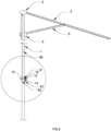
- the electrically-operated umbrella comprises a column being hollow; an upper tray attached to top of the column; a lower tray slidably fitted onto the column; a plurality of long rods movably connected to the upper tray; a plurality of short rods movably connected to the lower tray; and a rope extending inside the column; characterized in that, the lower tray is capable of sliding upward and downward along the column; each long rod is rotatably hinged to the upper tray, and one end of each short rod is hinged to the lower tray, while the other end of each short rod is hinged to each long rod, forming an umbrella frame; a housing is attached to a lower portion of the column; a rotatable rope shaft, a motor for rotating the rope shaft, and a transmission mechanism are placed inside the housing; the rope shaft is traversely disposed across the column through a plurality of fixation seats; one end of the rope is connected to the rope shaft, and the other end of the rope runs upward through the upper tray inside the column and then runs downward
- a through hole for receiving the rope shaft is radially disposed in the lower portion of the column;
- the plurality of fixation seats are composed of a left fixation seat and a right fixation seat, which symmetrically disposed on left and right sides of the column, a plurality of connecting holes are formed on upper and lower sides of the fixation seats, and the plurality of fixation seats are fixed to the column through a plurality of connecting members;
- a circular hole for receiving the left end of the rope shaft is formed in the middle of the left fixation seat, and a shaft seat for fixing and rotating the right end of the rope shaft is formed in the middle of the right fixation seat; and the right end of the rope shaft passes through the column to be inserted into the shaft seat of the right fixation seat, while the left end of the rope shaft passes through the column to be inserted into the circular hole of the left fixation seat and is connected to the transmission mechanism.
- the transmission mechanism comprises a transmission box, and a planetary gear set, a large spur gear and a small spur gear disposed in the transmission box;
- the transmission box comprises a transmission box seat and a transmission box cover;
- the transmission box seat is disposed on the left side of the left fixation seat, one end of the transmission box seat is fixed to the left fixation seat, and a mounting cylinder for receiving the planetary gear set is convexly disposed at the other end of the transmission box seat;
- the transmission box cover is disposed at a right opening of the mounting cylinder of the transmission box seat;
- the motor is fixedly mounted on the transmission box cover, and a motor shaft passes through the transmission box cover and is connected to the planetary gear set; and the other end of the planetary gear set is connected to the small spur gear through an output shaft.
- the large spur gear and the small spur gear are respectively disposed on the left side of the transmission box seat, and the large spur gear is meshed with the small spur gear;
- the output shaft is disposed at a position on the transmission box seat at the left opening of the mounting cylinder;
- a second circular hole corresponding to the circular hole in the middle of the left fixation seat is formed on the transmission box seat, and a driven shaft is disposed in the second circular hole; and one end of the driven shaft is connected to the large spur gear, and the other end thereof passes through the transmission box seat and is in transmission connection to the left end of the rope shaft through a reverse clutch.
- a convex ring is formed at a position on the left side of the left fixation seat corresponding to the circular hole in the middle, the reverse clutch is disposed in the convex ring, the left end of the rope shaft is formed as a square shaft end, and a corresponding square hole is formed in the center of the reverse clutch.
- a hexagonal groove convenient for manually opening or folding the umbrella is disposed at the left end of the driven shaft, and an opening corresponding to the hexagonal groove is disposed on the corresponding side of the housing.
- a positioning slot for receiving the battery is disposed on the right side of the housing, the battery is a rechargeable battery and is detachably inserted into the housing, and a USB interface is further disposed on the housing.
- control buttons respectively an opening button and a folding button
- the opening or folding of the umbrella is capable of being controlled by the control buttons or by a remote controller.
- a sensor electrically connected to the circuit board is disposed on the housing; when the framework is folded to the bottom end and the sensor detects the rods during folding, the circuit board stops supplying power and realizes automatic stopping after the umbrella is folded; and when the framework is completely opened, the resistance of the motor by the rope is increased, and the current in the motor is increased, and the circuit board automatically stops supplying power after detecting the current and realizes automatic stopping after the umbrella is opened.
- an automatic bending mechanism is additionally mounted on the middle column; the rope passes through the automatic bending mechanism and is connected to the lower tray; and when the rotation of the rope shaft drives the lower tray to move up to the top, the rope shaft is continuously rotated to drive the automatic bending mechanism to bend.
- the present invention has the following advantages.
- the rope shaft on the column By providing the rope shaft on the column and driving the rope shaft to rotate by the motor and the transmission mechanism, the rope is wound or loosen around the rope shaft, and the rope pulls the lower tray to move up and down along the column, so that the umbrella is electrically opened or folded.
- power can be cut off automatically.
- the sensor After the framework is folded, power can be cut off automatically to stop rotation.
- the USB interface power can be supplied to a mobile device.
- the present invention is rational and compact in structure, capable of electrically opening or folding the framework without manual operation, convenient and quick to use and low in cost and greatly improves the user's use experience, so it is worth popularizing.
- an electrically-operated umbrella comprises a column being hollow; an upper tray 2 attached to top of the column; a lower tray 3 slidably fitted onto the column; a plurality of long rods 4 movably connected to the upper tray; a plurality of short rods 5 movably connected to the lower tray; and a rope 80 extending inside the column; characterized in that, the lower tray 3 is capable of sliding upward and downward along the column 1; each long rod 4 is rotatably hinged to the upper tray 2, and one end of each short rod 5 is hinged to the lower tray 3, while the other end of each short rod 5 is hinged to each long rod 4, forming an umbrella frame; a housing 30 is attached to a lower portion of the column 1; a rotatable rope shaft 8, a motor 10 for rotating the rope shaft 8, and a transmission mechanism are placed inside the housing 30; the rope shaft 8 is traversely disposed across the column 1 through a plurality of fixation seats 6; one end of the rope 80 is connected
- a through hole for receiving the rope shaft 8 is radially disposed in the lower portion of the column 1;
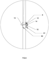
- the plurality of fixation seats 6 are composed of a left fixation seat 61 and a right fixation seat 62, which symmetrically disposed on left and right sides of the column 1, a plurality of connecting holes are formed on upper and lower sides of the fixation seats 6, and the plurality of fixation seats 6 are fixed to the column 1 through a plurality of connecting members;
- a circular hole 611 for receiving the left end of the rope shaft 8 is formed in the middle of the left fixation seat 61, and a shaft seat 621 for fixing and rotating the right end of the rope shaft 8 is formed in the middle of the right fixation seat 62; and the right end of the rope shaft 8 passes through the column 1 to be inserted into the shaft seat 621 of the right fixation seat 62, and a bearing convenient for rotating the rope shaft 8 is disposed in the shaft seat 621.
- the left end of the rope shaft 8 passes through the column 1 to be inserted into the circular hole 611 of the left fixation seat 61 and is connected to the transmission mechanism.
- the transmission mechanism comprises a transmission box 7, and a planetary gear set 9, a large spur gear 12 and a small spur gear 11 disposed in the transmission box 7.
- the planetary gear set 9 employs a tertiary planetary gear transmission.
- the planetary gear set may not be limited to the tertiary planetary gear transmission.
- the transmission box 7 comprises a transmission box seat 71 and a transmission box cover 72; the transmission box seat 71 is disposed on the left side of the left fixation seat 61, one end of the transmission box seat 71 is fixed to the left fixation seat 61, and a mounting cylinder 711 for receiving the planetary gear set 9 is convexly disposed at the other end of the transmission box seat 71; the transmission box cover 72 is disposed at a right opening of the mounting cylinder 711 of the transmission box seat 71; the motor 10 is fixedly mounted on the transmission box cover 72, and a motor shaft passes through the transmission box cover 72 and is connected to the planetary gear set 9; and the other end of the planetary gear set 9 is connected to the small spur gear 11 through an output shaft 13.
- the number of planetary gear sets 9 can be increased or decreased a required to adjust torque to adapt to different canopy areas.
- the large spur gear 12 and the small spur gear 11 are respectively disposed on the left side of the transmission box seat 71, and the large spur gear 12 is meshed with the small spur gear 11;
- the output shaft 13 is disposed at a position on the transmission box seat 71 at the left opening of the mounting cylinder 711;
- a second circular hole 712 corresponding to the circular hole 611 in the middle of the left fixation seat 61 is formed on the transmission box seat 71, and a driven shaft 14 is disposed in the second circular hole 712; and one end of the driven shaft 14 is connected to the large spur gear 12, and the other end thereof passes through the transmission box seat 71 and is in transmission connection to the left end of the rope shaft 8 through a reverse clutch 15.
- a convex ring is formed at a position on the left side of the left fixation seat 61 corresponding to the circular hole 611 in the middle, the reverse clutch 15 is disposed in the convex ring, the left end of the rope shaft 8 is formed as a square shaft end, and a corresponding square hole is formed in the center of the reverse clutch 15.
- the reverse clutch 15 is provided to enable the large spur gear 12 to drive the rope shaft 8 to rotate but not enable the rope shaft 8 to drive the large spur gear 8 to rotate, thereby preventing the rope shaft 8 from reservedly rotating by the pull force of the rope 80.
- the reverse clutch 15 employs a simple roller clutch; however, other one-way transmission clutches are also possible.
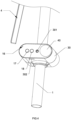
- a hexagonal groove 141 convenient for manually opening or folding the umbrella is disposed at the left end of the driven shaft 14, and an opening 301 corresponding to the hexagonal groove 141 is disposed on the corresponding side of the housing 30. In this way, when the battery level is insufficient, the rope shaft 8 can be manually driven by a hexagon wrench to open and fold the umbrella.
- a positioning slot for receiving the battery 40 is disposed on the right side of the housing 30, the battery 40 is a rechargeable battery and is detachably inserted into the housing 30, and a USB interface 302 is further disposed on the housing 30, so that a mobile device can be charged.
- a sensor 16 electrically connected to the circuit board is disposed on the housing 30; when the framework is folded to the bottom end and the sensor 16 detects the long rods 4 during folding, the circuit board stops supplying power and realizes automatic stopping after the umbrella is folded; and when the framework is completely opened, the resistance of the motor 10 by the rope 80 is increased, and the current in the motor 10 is increased, and the circuit board automatically stops supplying power after detecting the current and realizes automatic stopping after the umbrella is opened.
- the opening button 17 When the umbrella should be opened, the opening button 17 is pressed down; the motor 10 is powered on to drive the planetary gear set 9 to rotate; the planetary gear seat 9 drives the output shaft 13 to rotate; the output shaft 13 drives the small spur gear 11 to rotate; the small spur gear 11 drives the large spur gear 12 to rotate; the large spur gear 12 drives the driven shaft 14 to rotate; the driven shaft 14 drives the reverse clutch 15 to rotate; and the reverse clutch 15 drives the rope shaft 8 to rotate.
- the rope shaft 8 winds the rope 80 during its rotation, and the rope 80 pulls the lower tray 3 to move up. After the lower tray 3 is moved to the top end, the rope 80 is tensioned, and the motor 10 cannot rotate. At this time, the current in the motor 10 is continuously increased. When the current in the motor 10 is increased to a preset value, power is automatically cut off to open the umbrella.
- the lower tray 3 will tend to move down due to the wind force, gravity or the like, so as to compel the rope 80 to drive the rope shaft 8 to rotate reversely.
- the rope shaft 8 triggers the reverse clutch 15 so that the rope shaft 8 cannot rotate.
- the lower tray 3 is fixed.
- the folding button 18 When the umbrella should be folded, the folding button 18 is pressed, the motor 10 is rotated reversely to drive the lower tray 3 to move down, and the long rods 4 are folded to approach to the housing 30.
- the circuit board stops supplying power, and the motor 10 is automatically powered off and stops rotating, so that the umbrella is folded.
- a manual operation can be performed by a hexagon wrench through the hexagonal groove 141 at the tail end of the driven shaft 14 to open or fold the umbrella.
- the user can supply power to a mobile device by using the USB interface 302 on the bottom of the housing 30.
- the battery 40 can be taken out for charging.
- an electrically-operated umbrella comprises an upper tray 2, a lower tray 3, long rods 4, short rods 5 and a column 1.
- a rope shaft 8, a left fixation seat 61, a right fixation seat 62, a transmission mechanism, a motor and other components are mounted on the column.
- the umbrella of this embodiment differs from that of Embodiment 1 in that, an automatic bending mechanism 20 is additionally mounted on the column 1.
- the structure and principle of the automatic bending mechanism 20 are the same as those described in Patent No. US8272391B2 /LZ201020556192.1/Nr.202010011240.0, and will not be specifically described here.
- the rope 80 passes through the automatic bending mechanism 20 and is connected to the lower tray 3; and when the rotation of the rope shaft 8 drives the lower tray 3 to move up to the top, the rope shaft 8 is continuously rotated to drive the automatic bending mechanism 20 to bend.
Landscapes
- Walking Sticks, Umbrellas, And Fans (AREA)
- Holders For Apparel And Elements Relating To Apparel (AREA)
Claims (5)
- Elektrisch betriebener Schirm, umfassend:einen Stock (1), der hohl ist;einen oberen Teller (2), der an der Oberseite des Stocks angebracht ist;einen unteren Teller (3), der verschiebbar auf den Stock gesetzt ist;eine Vielzahl von langen Schienen (4), die beweglich mit dem oberen Teller verbunden ist;eine Vielzahl von kurzen Schienen (5), die beweglich mit dem unteren Teller verbunden ist; undein Seil (80), das sich im Stock erstreckt;wobei der untere Teller am Stock auf und ab gleiten kann;wobei jede lange Schiene drehbar an dem oberen Teller angebracht ist und ein Ende jeder kurzen Schiene drehbar an dem unteren Teller angebracht ist, während das andere Ende jeder kurzen Schiene drehbar an einer jeweiligen langen Schiene angebracht ist, wodurch ein Schirmgestell gebildet wird;wobei ein Gehäuse (30) an einem unteren Abschnitt des Stocks angebracht ist;wobei eine drehbare Seilwelle (8), ein Motor (10) zum Drehen der Seilwelle und ein Getriebemechanismus im Inneren des Gehäuses angeordnet sind;wobei die Seilwelle durch eine Vielzahl von Fixierungssitzen (6) quer über den Stock angeordnet ist;wobei ein Ende des Seils mit der Seilwelle verbunden ist und das andere Ende des Seils durch den oberen Teller im Inneren des Stocks und dann nach unten verläuft, sodass es mit dem unteren Teller verbunden ist;wobei ferner eine Batterie (40) und eine Leiterplatte im Inneren des Gehäuses angeordnet sind und eine Steuertaste (17, 18), die mit der Leiterplatte verbunden ist, an dem Gehäuse angeordnet ist, sodass sie eine Steuerschaltung des Motors bildet;dadurch gekennzeichnet, dass ein Durchgangsloch zum Aufnehmen der Seilwelle radial im unteren Abschnitt des Stocks angeordnet ist;wobei die Vielzahl von Fixierungssitzen aus einem linken Fixierungssitz (611) und einem rechten Fixierungssitz (62) zusammengesetzt ist, die symmetrisch auf der linken und rechten Seite des Stocks angeordnet sind, eine Vielzahl von Verbindungslöchern an der oberen und unteren Seite der Fixierungssitze gebildet ist und die Vielzahl von Fixierungssitzen durch eine Vielzahl von Verbindungselementen an dem Stock fixiert ist;wobei ein kreisförmiges Loch (611) zum Aufnehmen des linken Endes der Seilwelle in der Mitte des linken Fixierungssitzes gebildet ist und ein Wellensitz (62) zum Fixieren und Drehen des rechten Endes der Seilwelle in der Mitte des rechten Fixierungssitzes gebildet ist; undwobei das rechte Ende der Seilwelle durch den Stock verläuft und in den Wellensitz des rechten Fixierungssitzes eingeführt ist, während das linke Ende der Seilwelle durch den Stock verläuft und in das kreisförmige Loch des linken Fixierungssitzes eingeführt und mit dem Getriebemechanismus verbunden ist;wobei der Getriebemechanismus einen Getriebekasten (7) umfasst und ein Planetenradsatz (9), ein großes Stirnrad (12) und ein kleines Stirnrad (11) in dem Getriebekasten angeordnet sind;wobei der Getriebekasten (7) einen Getriebekastensitz (71) und eine Getriebekastenabdeckung (72) umfasst;wobei der Getriebekastensitz auf der linken Seite des linken Fixierungssitzes (61) angeordnet ist, ein Ende des Getriebekastensitzes an dem linken Fixierungssitz fixiert ist und ein Montagezylinder (711) zum Aufnehmen des Planetenradsatzes konvex am anderen Ende des Getriebekastensitzes angeordnet ist;wobei die Getriebekastenabdeckung an einer rechten Öffnung des Montagezylinders des Getriebekastensitzes angeordnet ist;wobei der Motor fest an der Getriebekastenabdeckung montiert ist und eine Motorwelle durch die Getriebekastenabdeckung verläuft und mit dem Planetenradsatz verbunden ist; undwobei das andere Ende des Planetenradsatzes durch eine Ausgangswelle (13) mit dem kleinen Stirnrad verbunden ist;wobei das große Stirnrad und das kleine Stirnrad jeweils auf der linken Seite des Getriebekastensitzes angeordnet sind und das große Stirnrad mit dem kleinen Stirnrad verzahnt ist;wobei die Ausgangswelle an einer Position des Getriebekastensitzes an der linken Öffnung des Montagezylinders angeordnet ist;wobei ein zweites kreisförmiges Loch (712), das dem kreisförmigen Loch in der Mitte des linken Fixierungssitzes entspricht, an dem Getriebekastensitz gebildet ist, und eine Abtriebswelle (14) in dem zweiten kreisförmigen Loch angeordnet ist; undwobei ein Ende der Abtriebswelle mit dem großen Stirnrad verbunden ist und ihr anderes Ende durch den Getriebekastensitz verläuft und durch eine Umkehrkupplung (15) in Übertragungsverbindung mit dem linken Ende der Seilwelle steht;wobei ein konvexer Ring an einer Position auf der linken Seite des linken Fixierungssitzes gebildet ist, der dem kreisförmigen Loch in der Mitte entspricht, die Umkehrkupplung in dem konvexen Ring angeordnet ist, das linke Ende der Seilwelle als ein quadratisches Wellenende gebildet ist und ein entsprechendes quadratisches Loch in der Mitte der Umkehrkupplung gebildet ist.
- Schirm nach Anspruch 1, dadurch gekennzeichnet, dass eine Sechskantnut (141), die für manuelles Öffnen oder Zusammenfalten des Schirms praktisch ist, am linken Ende der Abtriebswelle angeordnet ist, und eine der Sechskantnut entsprechende Öffnung (301) auf der entsprechenden Seite des Gehäuses angeordnet ist.
- Schirm nach einem der Ansprüche 1-2, dadurch gekennzeichnet, dass ein Positionierungsschlitz zum Aufnehmen der Batterie auf der rechten Seite des Gehäuses angeordnet ist, die Batterie eine wiederaufladbare Batterie ist und lösbar in das Gehäuse eingesetzt ist und ferner eine USB-Schnittstelle (302) an dem Gehäuse angeordnet ist.
- Schirm nach einem der Ansprüche 1-2, dadurch gekennzeichnet, dass zwei Steuertasten vorliegen, nämlich eine Öffnungstaste (17) und eine Zusammenfalttaste (18), und das Öffnen oder Zusammenfalten des Schirms durch die Steuertasten oder durch eine Fernbedienung gesteuert werden.
- Schirm nach einem der Ansprüche 1-2, dadurch gekennzeichnet, dass ein Sensor (16), der elektrisch mit der Leiterplatte verbunden ist, an dem Gehäuse angeordnet ist;wobei, wenn der Sensor beim Zusammenfalten des Gerippes zum unteren Ende die Schienen erfasst, die Leiterplatte das Zuführen von Leistung anhält und nach dem Zusammenfalten des Schirms einen automatischen Halte bewirkt; undwenn das Gerippe vollständig geöffnet ist, der Widerstand des Motors durch das Seil erhöht wird und der Strom im Motor erhöht wird und die Leiterplatte das Zuführen von Leistung automatisch anhält, sobald sie den Strom erfasst, und nach dem Öffnen des Schirms einen automatischen Halte bewirkt.
Applications Claiming Priority (2)
| Application Number | Priority Date | Filing Date | Title |
|---|---|---|---|
| CN201911140073.XA CN110934393A (zh) | 2019-11-20 | 2019-11-20 | 一种电动开合的遮阳伞 |
| PCT/CN2020/072344 WO2021098036A1 (zh) | 2019-11-20 | 2020-01-16 | 一种电动开合的遮阳伞 |
Publications (3)
| Publication Number | Publication Date |
|---|---|
| EP4059375A1 EP4059375A1 (de) | 2022-09-21 |
| EP4059375A4 EP4059375A4 (de) | 2022-12-21 |
| EP4059375B1 true EP4059375B1 (de) | 2024-12-04 |
Family
ID=69906958
Family Applications (1)
| Application Number | Title | Priority Date | Filing Date |
|---|---|---|---|
| EP20891175.0A Active EP4059375B1 (de) | 2019-11-20 | 2020-01-16 | Sonnenschirm mit elektrischer öffnung/schliessung |
Country Status (4)
| Country | Link |
|---|---|
| US (1) | US11903464B2 (de) |
| EP (1) | EP4059375B1 (de) |
| CN (1) | CN110934393A (de) |
| WO (1) | WO2021098036A1 (de) |
Families Citing this family (8)
| Publication number | Priority date | Publication date | Assignee | Title |
|---|---|---|---|---|
| CN111972796A (zh) * | 2020-09-23 | 2020-11-24 | 广东迈牛科技有限公司 | 一种自动遮阳伞架 |
| CN111972794A (zh) * | 2020-09-23 | 2020-11-24 | 广东迈牛科技有限公司 | 一种自动收展遮阳伞架 |
| USD1046434S1 (en) * | 2023-01-13 | 2024-10-15 | Linhai Jiade Leisure Products Co., Ltd | Push-up straight parasol |
| CN116211037A (zh) * | 2023-04-14 | 2023-06-06 | 浙江乐居户外用品有限公司 | 一种智能伞 |
| CN117084489A (zh) * | 2023-08-29 | 2023-11-21 | 浙江永强集团股份有限公司 | 一种无短伞骨开合的电动直杆伞 |
| CN117122136B (zh) * | 2023-08-31 | 2026-03-20 | 雷力户外伞业(广州)有限公司 | 一种开收伞机构及旋转开合伞 |
| USD1053552S1 (en) * | 2024-06-21 | 2024-12-10 | Mengling Liao | Umbrella base |
| WO2026078453A1 (en) * | 2024-10-09 | 2026-04-16 | Ombrellificio Ciccarese di Salvatore Ciccarese | Smart umbrella for computerized beach resorts |
Family Cites Families (39)
| Publication number | Priority date | Publication date | Assignee | Title |
|---|---|---|---|---|
| US2721569A (en) * | 1954-08-13 | 1955-10-25 | Finkel Umbrella Frame Company | Tiltable garden umbrella |
| US2960094A (en) * | 1957-12-03 | 1960-11-15 | Cohen Alfred G | Solar actuated umbrella raising mechanism |
| US3150671A (en) * | 1963-01-14 | 1964-09-29 | Robert C Hatcher | Tiltable umbrella |
| US6182917B1 (en) * | 1999-06-02 | 2001-02-06 | Great Mission Trading Limited | Electric stretching/collecting device for a parasol |
| FR2799486B1 (fr) * | 1999-10-12 | 2002-05-17 | Neyrat Peyronie | Parasol motorise |
| US6446650B1 (en) * | 2000-12-13 | 2002-09-10 | Treasure Garden, Inc. | Tilt device for patio umbrella |
| US8069868B2 (en) * | 2001-02-07 | 2011-12-06 | World Factory, Inc. | Umbrella apparatus |
| CN2652206Y (zh) * | 2003-07-24 | 2004-11-03 | 吴伟淡 | 电动遮阳吊伞 |
| US7188633B2 (en) * | 2003-12-17 | 2007-03-13 | Michael Anthony Zerillo | Retrofit motor and control for patio umbrellas |
| US7051744B2 (en) * | 2004-04-12 | 2006-05-30 | Hsi-Lu Hung | Sunshade structure operated easily |
| CN201019119Y (zh) * | 2007-01-12 | 2008-02-13 | 陈科全 | 无线遥控自动开合伞 |
| CN201108109Y (zh) * | 2007-09-30 | 2008-09-03 | 许翠娅 | 电动式自动伞 |
| US8297294B2 (en) * | 2007-11-14 | 2012-10-30 | Oliver Joen-An Ma | Rechargeable battery arrangement for electrical system of outdoor shading device |
| CN101433395B (zh) * | 2008-11-07 | 2011-06-29 | 深圳优利伞业有限公司 | 一种自动开合伞 |
| CN201480256U (zh) * | 2009-08-17 | 2010-05-26 | 浙江能福旅游用品有限公司 | 一种遮阳伞的开合装置 |
| CN201563783U (zh) * | 2009-10-19 | 2010-09-01 | 唐兴志 | 一种全自动雨伞 |
| CN201860952U (zh) * | 2010-10-08 | 2011-06-15 | 罗雄 | 一种遮阳伞的弯向结构 |
| US8272391B2 (en) * | 2009-11-30 | 2012-09-25 | Luo Xiong | Auto bending structure of sunshade |
| US8544485B2 (en) * | 2009-12-08 | 2013-10-01 | Chin Sung Ko | Structure of self-closing collapsible umbrella |
| CN202269504U (zh) * | 2011-10-29 | 2012-06-13 | 浙江正特集团有限公司 | 一种电动式遮阳伞 |
| CN102599697B (zh) * | 2012-03-27 | 2014-07-09 | 厦门明和实业有限公司 | 全自动直骨开收伞 |
| CN202774562U (zh) * | 2012-06-18 | 2013-03-13 | 宁波万汇休闲用品有限公司 | 伞面角度调节机构 |
| US8757183B2 (en) * | 2012-10-05 | 2014-06-24 | Dee Volin | Solar-powered pulley-assisted umbrella having simultaneously and oppositely movable top-and-bottom weighted brackets |
| CN103859732A (zh) * | 2012-12-12 | 2014-06-18 | 周金雄 | 能够自动打开和自动收合的全自动伞 |
| CN203735617U (zh) * | 2014-02-24 | 2014-07-30 | 佳祥有限公司 | 一种遥控和触摸控制led太阳伞 |
| CN204467194U (zh) * | 2015-01-05 | 2015-07-15 | 临海市美阳伞业有限公司 | 一种用于遮阳伞的开伞控制机构 |
| US10519713B2 (en) * | 2015-07-01 | 2019-12-31 | Hunter Douglas Inc. | Static mitigation end cap for a covering for an architectural opening |
| DE102016207129A1 (de) * | 2015-12-23 | 2017-06-29 | Brose Fahrzeugteile GmbH & Co. Kommanditgesellschaft, Würzburg | Verfahren zum Betrieb eines elektromotorischen Kältemittelverdichters |
| CN205456660U (zh) * | 2016-01-25 | 2016-08-17 | 谢溢河 | 螺杆拉绳多折电动伞 |
| KR101933485B1 (ko) * | 2016-02-01 | 2018-12-31 | 진전양 | 자동우산 |
| CN205624866U (zh) * | 2016-05-19 | 2016-10-12 | 浙江永强集团股份有限公司 | 一种自动与非自动结合的伞具开合结构 |
| CN106205390B (zh) * | 2016-07-08 | 2018-03-27 | 广东欧珀移动通信有限公司 | 一种电子设备控制方法及电子设备 |
| US9968168B2 (en) * | 2016-09-19 | 2018-05-15 | Oliver Jeon-an MA | Functional umbrella |
| MX2019008461A (es) * | 2017-01-16 | 2019-09-18 | Neubourg Skin Care Gmbh & Co Kg | Aparato para el diagnostico de pie diabetico. |
| CN107280173A (zh) * | 2017-05-16 | 2017-10-24 | 安徽甬安雨具有限公司 | 一种大型自动开启固定遮雨伞 |
| CN108991667A (zh) * | 2017-06-07 | 2018-12-14 | 孙建 | 一种全自动开合雨伞 |
| US10794442B2 (en) * | 2018-02-06 | 2020-10-06 | Mando Corporation | Electromechanical actuator package with multi-stage belt drive mechanism |
| CN110393347B (zh) * | 2019-07-12 | 2024-09-03 | 江苏腾魄休闲用品有限公司 | 一种快速开合的大型遮阳伞 |
| CN211483232U (zh) * | 2019-11-20 | 2020-09-15 | 江苏腾魄休闲用品有限公司 | 一种电动开合的遮阳伞 |
-
2019
- 2019-11-20 CN CN201911140073.XA patent/CN110934393A/zh active Pending
-
2020
- 2020-01-16 WO PCT/CN2020/072344 patent/WO2021098036A1/zh not_active Ceased
- 2020-01-16 EP EP20891175.0A patent/EP4059375B1/de active Active
- 2020-01-16 US US17/755,476 patent/US11903464B2/en active Active
Also Published As
| Publication number | Publication date |
|---|---|
| CN110934393A (zh) | 2020-03-31 |
| US20220369776A1 (en) | 2022-11-24 |
| US11903464B2 (en) | 2024-02-20 |
| EP4059375A1 (de) | 2022-09-21 |
| WO2021098036A1 (zh) | 2021-05-27 |
| EP4059375A4 (de) | 2022-12-21 |
Similar Documents
| Publication | Publication Date | Title |
|---|---|---|
| EP4059375B1 (de) | Sonnenschirm mit elektrischer öffnung/schliessung | |
| US10653218B1 (en) | Umbrella with projector lighting device | |
| US20040055627A1 (en) | Umbrella and kit therefor | |
| US10357087B2 (en) | Umbrella system | |
| CN102258250B (zh) | 太阳能电动遥控遮阳吊伞及其控制方法 | |
| EP3135149A1 (de) | Sonnenblende und beschattungssystem | |
| US20130306118A1 (en) | Motor-operated umbrella | |
| US20250275612A1 (en) | Electric Umbrella | |
| CN202698003U (zh) | 遥控太阳能自动雨伞 | |
| CN101433395B (zh) | 一种自动开合伞 | |
| CN211483232U (zh) | 一种电动开合的遮阳伞 | |
| CN115708614B (zh) | 一种具有自助力扶手机构的户外伞 | |
| CN110074528B (zh) | 一种两折中棒的三折电动伞 | |
| CN107997320B (zh) | 一种多功能背包伞 | |
| CN202179221U (zh) | 太阳能电动遥控遮阳吊伞 | |
| CN201813995U (zh) | 一种电动伞 | |
| CN109998241B (zh) | 一种两折电动伞 | |
| CN104138112A (zh) | 自动太阳伞 | |
| CN218942467U (zh) | 一种手自一体的电动伞 | |
| CN203538560U (zh) | 自动太阳伞 | |
| CN101999785A (zh) | 一种电动伞 | |
| CN201349628Y (zh) | 一种自动开合伞 | |
| CN210611271U (zh) | 一种具有伸展收缩伞面结构的遮阳伞及其立杆组件 | |
| CN201894267U (zh) | 一种新型的便携式遥控遮阳伞 | |
| CN222017856U (zh) | 双驱动的电动遮阳伞 |
Legal Events
| Date | Code | Title | Description |
|---|---|---|---|
| STAA | Information on the status of an ep patent application or granted ep patent |
Free format text: STATUS: THE INTERNATIONAL PUBLICATION HAS BEEN MADE |
|
| PUAI | Public reference made under article 153(3) epc to a published international application that has entered the european phase |
Free format text: ORIGINAL CODE: 0009012 |
|
| STAA | Information on the status of an ep patent application or granted ep patent |
Free format text: STATUS: REQUEST FOR EXAMINATION WAS MADE |
|
| 17P | Request for examination filed |
Effective date: 20220617 |
|
| AK | Designated contracting states |
Kind code of ref document: A1 Designated state(s): AL AT BE BG CH CY CZ DE DK EE ES FI FR GB GR HR HU IE IS IT LI LT LU LV MC MK MT NL NO PL PT RO RS SE SI SK SM TR |
|
| A4 | Supplementary search report drawn up and despatched |
Effective date: 20221122 |
|
| RIC1 | Information provided on ipc code assigned before grant |
Ipc: A45B 25/14 20060101ALI20221116BHEP Ipc: A45B 25/16 20060101AFI20221116BHEP |
|
| DAV | Request for validation of the european patent (deleted) | ||
| DAX | Request for extension of the european patent (deleted) | ||
| GRAP | Despatch of communication of intention to grant a patent |
Free format text: ORIGINAL CODE: EPIDOSNIGR1 |
|
| STAA | Information on the status of an ep patent application or granted ep patent |
Free format text: STATUS: GRANT OF PATENT IS INTENDED |
|
| INTG | Intention to grant announced |
Effective date: 20240627 |
|
| GRAS | Grant fee paid |
Free format text: ORIGINAL CODE: EPIDOSNIGR3 |
|
| GRAA | (expected) grant |
Free format text: ORIGINAL CODE: 0009210 |
|
| STAA | Information on the status of an ep patent application or granted ep patent |
Free format text: STATUS: THE PATENT HAS BEEN GRANTED |
|
| AK | Designated contracting states |
Kind code of ref document: B1 Designated state(s): AL AT BE BG CH CY CZ DE DK EE ES FI FR GB GR HR HU IE IS IT LI LT LU LV MC MK MT NL NO PL PT RO RS SE SI SK SM TR |
|
| REG | Reference to a national code |
Ref country code: CH Ref legal event code: EP |
|
| REG | Reference to a national code |
Ref country code: DE Ref legal event code: R096 Ref document number: 602020042774 Country of ref document: DE |
|
| REG | Reference to a national code |
Ref country code: IE Ref legal event code: FG4D |
|
| REG | Reference to a national code |
Ref country code: NL Ref legal event code: FP |
|
| REG | Reference to a national code |
Ref country code: LT Ref legal event code: MG9D |
|
| PG25 | Lapsed in a contracting state [announced via postgrant information from national office to epo] |
Ref country code: HR Free format text: LAPSE BECAUSE OF FAILURE TO SUBMIT A TRANSLATION OF THE DESCRIPTION OR TO PAY THE FEE WITHIN THE PRESCRIBED TIME-LIMIT Effective date: 20241204 |
|
| PG25 | Lapsed in a contracting state [announced via postgrant information from national office to epo] |
Ref country code: FI Free format text: LAPSE BECAUSE OF FAILURE TO SUBMIT A TRANSLATION OF THE DESCRIPTION OR TO PAY THE FEE WITHIN THE PRESCRIBED TIME-LIMIT Effective date: 20241204 |
|
| PG25 | Lapsed in a contracting state [announced via postgrant information from national office to epo] |
Ref country code: BG Free format text: LAPSE BECAUSE OF FAILURE TO SUBMIT A TRANSLATION OF THE DESCRIPTION OR TO PAY THE FEE WITHIN THE PRESCRIBED TIME-LIMIT Effective date: 20241204 |
|
| PG25 | Lapsed in a contracting state [announced via postgrant information from national office to epo] |
Ref country code: ES Free format text: LAPSE BECAUSE OF FAILURE TO SUBMIT A TRANSLATION OF THE DESCRIPTION OR TO PAY THE FEE WITHIN THE PRESCRIBED TIME-LIMIT Effective date: 20241204 |
|
| PG25 | Lapsed in a contracting state [announced via postgrant information from national office to epo] |
Ref country code: NO Free format text: LAPSE BECAUSE OF FAILURE TO SUBMIT A TRANSLATION OF THE DESCRIPTION OR TO PAY THE FEE WITHIN THE PRESCRIBED TIME-LIMIT Effective date: 20250304 |
|
| PG25 | Lapsed in a contracting state [announced via postgrant information from national office to epo] |
Ref country code: GR Free format text: LAPSE BECAUSE OF FAILURE TO SUBMIT A TRANSLATION OF THE DESCRIPTION OR TO PAY THE FEE WITHIN THE PRESCRIBED TIME-LIMIT Effective date: 20250305 Ref country code: LV Free format text: LAPSE BECAUSE OF FAILURE TO SUBMIT A TRANSLATION OF THE DESCRIPTION OR TO PAY THE FEE WITHIN THE PRESCRIBED TIME-LIMIT Effective date: 20241204 |
|
| PG25 | Lapsed in a contracting state [announced via postgrant information from national office to epo] |
Ref country code: RS Free format text: LAPSE BECAUSE OF FAILURE TO SUBMIT A TRANSLATION OF THE DESCRIPTION OR TO PAY THE FEE WITHIN THE PRESCRIBED TIME-LIMIT Effective date: 20250304 |
|
| REG | Reference to a national code |
Ref country code: AT Ref legal event code: MK05 Ref document number: 1747166 Country of ref document: AT Kind code of ref document: T Effective date: 20241204 |
|
| PG25 | Lapsed in a contracting state [announced via postgrant information from national office to epo] |
Ref country code: SM Free format text: LAPSE BECAUSE OF FAILURE TO SUBMIT A TRANSLATION OF THE DESCRIPTION OR TO PAY THE FEE WITHIN THE PRESCRIBED TIME-LIMIT Effective date: 20241204 |
|
| PG25 | Lapsed in a contracting state [announced via postgrant information from national office to epo] |
Ref country code: PL Free format text: LAPSE BECAUSE OF FAILURE TO SUBMIT A TRANSLATION OF THE DESCRIPTION OR TO PAY THE FEE WITHIN THE PRESCRIBED TIME-LIMIT Effective date: 20241204 |
|
| PG25 | Lapsed in a contracting state [announced via postgrant information from national office to epo] |
Ref country code: IS Free format text: LAPSE BECAUSE OF FAILURE TO SUBMIT A TRANSLATION OF THE DESCRIPTION OR TO PAY THE FEE WITHIN THE PRESCRIBED TIME-LIMIT Effective date: 20250404 |
|
| PG25 | Lapsed in a contracting state [announced via postgrant information from national office to epo] |
Ref country code: PT Free format text: LAPSE BECAUSE OF FAILURE TO SUBMIT A TRANSLATION OF THE DESCRIPTION OR TO PAY THE FEE WITHIN THE PRESCRIBED TIME-LIMIT Effective date: 20250404 |
|
| PG25 | Lapsed in a contracting state [announced via postgrant information from national office to epo] |
Ref country code: EE Free format text: LAPSE BECAUSE OF FAILURE TO SUBMIT A TRANSLATION OF THE DESCRIPTION OR TO PAY THE FEE WITHIN THE PRESCRIBED TIME-LIMIT Effective date: 20241204 |
|
| PG25 | Lapsed in a contracting state [announced via postgrant information from national office to epo] |
Ref country code: AT Free format text: LAPSE BECAUSE OF FAILURE TO SUBMIT A TRANSLATION OF THE DESCRIPTION OR TO PAY THE FEE WITHIN THE PRESCRIBED TIME-LIMIT Effective date: 20241204 Ref country code: RO Free format text: LAPSE BECAUSE OF FAILURE TO SUBMIT A TRANSLATION OF THE DESCRIPTION OR TO PAY THE FEE WITHIN THE PRESCRIBED TIME-LIMIT Effective date: 20241204 |
|
| PG25 | Lapsed in a contracting state [announced via postgrant information from national office to epo] |
Ref country code: SK Free format text: LAPSE BECAUSE OF FAILURE TO SUBMIT A TRANSLATION OF THE DESCRIPTION OR TO PAY THE FEE WITHIN THE PRESCRIBED TIME-LIMIT Effective date: 20241204 |
|
| PG25 | Lapsed in a contracting state [announced via postgrant information from national office to epo] |
Ref country code: CZ Free format text: LAPSE BECAUSE OF FAILURE TO SUBMIT A TRANSLATION OF THE DESCRIPTION OR TO PAY THE FEE WITHIN THE PRESCRIBED TIME-LIMIT Effective date: 20241204 |
|
| PG25 | Lapsed in a contracting state [announced via postgrant information from national office to epo] |
Ref country code: IT Free format text: LAPSE BECAUSE OF FAILURE TO SUBMIT A TRANSLATION OF THE DESCRIPTION OR TO PAY THE FEE WITHIN THE PRESCRIBED TIME-LIMIT Effective date: 20241204 |
|
| REG | Reference to a national code |
Ref country code: CH Ref legal event code: PL |
|
| REG | Reference to a national code |
Ref country code: DE Ref legal event code: R097 Ref document number: 602020042774 Country of ref document: DE |
|
| PG25 | Lapsed in a contracting state [announced via postgrant information from national office to epo] |
Ref country code: SE Free format text: LAPSE BECAUSE OF FAILURE TO SUBMIT A TRANSLATION OF THE DESCRIPTION OR TO PAY THE FEE WITHIN THE PRESCRIBED TIME-LIMIT Effective date: 20241204 |
|
| PG25 | Lapsed in a contracting state [announced via postgrant information from national office to epo] |
Ref country code: MC Free format text: LAPSE BECAUSE OF FAILURE TO SUBMIT A TRANSLATION OF THE DESCRIPTION OR TO PAY THE FEE WITHIN THE PRESCRIBED TIME-LIMIT Effective date: 20241204 Ref country code: LU Free format text: LAPSE BECAUSE OF NON-PAYMENT OF DUE FEES Effective date: 20250116 |
|
| PG25 | Lapsed in a contracting state [announced via postgrant information from national office to epo] |
Ref country code: DK Free format text: LAPSE BECAUSE OF FAILURE TO SUBMIT A TRANSLATION OF THE DESCRIPTION OR TO PAY THE FEE WITHIN THE PRESCRIBED TIME-LIMIT Effective date: 20241204 |
|
| PLBE | No opposition filed within time limit |
Free format text: ORIGINAL CODE: 0009261 |
|
| STAA | Information on the status of an ep patent application or granted ep patent |
Free format text: STATUS: NO OPPOSITION FILED WITHIN TIME LIMIT |
|
| PG25 | Lapsed in a contracting state [announced via postgrant information from national office to epo] |
Ref country code: BE Free format text: LAPSE BECAUSE OF NON-PAYMENT OF DUE FEES Effective date: 20250131 |
|
| PG25 | Lapsed in a contracting state [announced via postgrant information from national office to epo] |
Ref country code: CH Free format text: LAPSE BECAUSE OF NON-PAYMENT OF DUE FEES Effective date: 20250131 |
|
| REG | Reference to a national code |
Ref country code: BE Ref legal event code: MM Effective date: 20250131 |
|
| 26N | No opposition filed |
Effective date: 20250905 |
|
| PG25 | Lapsed in a contracting state [announced via postgrant information from national office to epo] |
Ref country code: IE Free format text: LAPSE BECAUSE OF NON-PAYMENT OF DUE FEES Effective date: 20250116 |
|
| PGFP | Annual fee paid to national office [announced via postgrant information from national office to epo] |
Ref country code: NL Payment date: 20260130 Year of fee payment: 7 |
|
| PGFP | Annual fee paid to national office [announced via postgrant information from national office to epo] |
Ref country code: GB Payment date: 20260130 Year of fee payment: 7 |
|
| PGFP | Annual fee paid to national office [announced via postgrant information from national office to epo] |
Ref country code: DE Payment date: 20260318 Year of fee payment: 7 |
|
| PGFP | Annual fee paid to national office [announced via postgrant information from national office to epo] |
Ref country code: FR Payment date: 20260202 Year of fee payment: 7 |