EP4058670B1 - Éolienne à pâles articulées dotée d'un axe incliné et/ou d'un rotor conique - Google Patents
Éolienne à pâles articulées dotée d'un axe incliné et/ou d'un rotor conique Download PDFInfo
- Publication number
- EP4058670B1 EP4058670B1 EP20810866.2A EP20810866A EP4058670B1 EP 4058670 B1 EP4058670 B1 EP 4058670B1 EP 20810866 A EP20810866 A EP 20810866A EP 4058670 B1 EP4058670 B1 EP 4058670B1
- Authority
- EP
- European Patent Office
- Prior art keywords
- wind turbine
- blade
- angle
- tower
- hinge
- Prior art date
- Legal status (The legal status is an assumption and is not a legal conclusion. Google has not performed a legal analysis and makes no representation as to the accuracy of the status listed.)
- Active
Links
Images


Classifications
-
- F—MECHANICAL ENGINEERING; LIGHTING; HEATING; WEAPONS; BLASTING
- F03—MACHINES OR ENGINES FOR LIQUIDS; WIND, SPRING, OR WEIGHT MOTORS; PRODUCING MECHANICAL POWER OR A REACTIVE PROPULSIVE THRUST, NOT OTHERWISE PROVIDED FOR
- F03D—WIND MOTORS
- F03D1/00—Wind motors with rotation axis substantially parallel to the air flow entering the rotor
- F03D1/06—Rotors
- F03D1/0608—Rotors characterised by their aerodynamic shape
- F03D1/0633—Rotors characterised by their aerodynamic shape of the blades
-
- F—MECHANICAL ENGINEERING; LIGHTING; HEATING; WEAPONS; BLASTING
- F03—MACHINES OR ENGINES FOR LIQUIDS; WIND, SPRING, OR WEIGHT MOTORS; PRODUCING MECHANICAL POWER OR A REACTIVE PROPULSIVE THRUST, NOT OTHERWISE PROVIDED FOR
- F03D—WIND MOTORS
- F03D1/00—Wind motors with rotation axis substantially parallel to the air flow entering the rotor
- F03D1/06—Rotors
- F03D1/065—Rotors characterised by their construction elements
- F03D1/0675—Rotors characterised by their construction elements of the blades
- F03D1/0677—Longitudinally segmented blades; Connectors therefor
-
- F—MECHANICAL ENGINEERING; LIGHTING; HEATING; WEAPONS; BLASTING
- F05—INDEXING SCHEMES RELATING TO ENGINES OR PUMPS IN VARIOUS SUBCLASSES OF CLASSES F01-F04
- F05B—INDEXING SCHEME RELATING TO WIND, SPRING, WEIGHT, INERTIA OR LIKE MOTORS, TO MACHINES OR ENGINES FOR LIQUIDS COVERED BY SUBCLASSES F03B, F03D AND F03G
- F05B2240/00—Components
- F05B2240/20—Rotors
- F05B2240/21—Rotors for wind turbines
- F05B2240/221—Rotors for wind turbines with horizontal axis
- F05B2240/2213—Rotors for wind turbines with horizontal axis and with the rotor downwind from the yaw pivot axis
-
- F—MECHANICAL ENGINEERING; LIGHTING; HEATING; WEAPONS; BLASTING
- F05—INDEXING SCHEMES RELATING TO ENGINES OR PUMPS IN VARIOUS SUBCLASSES OF CLASSES F01-F04
- F05B—INDEXING SCHEME RELATING TO WIND, SPRING, WEIGHT, INERTIA OR LIKE MOTORS, TO MACHINES OR ENGINES FOR LIQUIDS COVERED BY SUBCLASSES F03B, F03D AND F03G
- F05B2240/00—Components
- F05B2240/20—Rotors
- F05B2240/30—Characteristics of rotor blades, i.e. of any element transforming dynamic fluid energy to or from rotational energy and being attached to a rotor
- F05B2240/31—Characteristics of rotor blades, i.e. of any element transforming dynamic fluid energy to or from rotational energy and being attached to a rotor of changeable form or shape
-
- Y—GENERAL TAGGING OF NEW TECHNOLOGICAL DEVELOPMENTS; GENERAL TAGGING OF CROSS-SECTIONAL TECHNOLOGIES SPANNING OVER SEVERAL SECTIONS OF THE IPC; TECHNICAL SUBJECTS COVERED BY FORMER USPC CROSS-REFERENCE ART COLLECTIONS [XRACs] AND DIGESTS
- Y02—TECHNOLOGIES OR APPLICATIONS FOR MITIGATION OR ADAPTATION AGAINST CLIMATE CHANGE
- Y02E—REDUCTION OF GREENHOUSE GAS [GHG] EMISSIONS, RELATED TO ENERGY GENERATION, TRANSMISSION OR DISTRIBUTION
- Y02E10/00—Energy generation through renewable energy sources
- Y02E10/70—Wind energy
- Y02E10/72—Wind turbines with rotation axis in wind direction
Definitions
- the present invention relates to a wind turbine comprising a tower, a nacelle and a hub comprising a blade carrying structure and a use of such wind turbine.
- One or more wind turbine blades are each pivotally connected to the blade carrying structure via a hinge.
- the wind turbine of the invention further comprises a tilted rotor axis and/or a coned blade carrying structure.
- Wind turbines are normally controlled in order to provide a desired power output and in order to control loads on the wind turbine.
- For horizontal axis wind turbines i.e. wind turbines with a rotor which rotates about a substantially horizontal rotational axis, this may be obtained by controlling a pitch angle of the wind turbine blades.
- the angle of attack of the wind turbine blades relative to the incoming wind is adjusted by rotating the wind turbine blades about a longitudinal axis.
- US 4,632,637 discloses a high speed, downwind horizontal axis wind turbine having three circumferentially spaced lightweight blades having inner support arms radially outwardly disposed blade segments which are pivotally connected to the support arms, so as to fold straight downwind under high wind conditions or high rotating speeds.
- a wind turbine with a tilted rotor axis is known e.g. from EP 2 598 750 A2 .
- a wind turbine comprising:
- the distance between the hinge and the tower at a vertical position defined by a position of the hinge at tower passage is relatively larger with respect to a wind turbine with zero coning angle and/or tilt angle, which in turn enables that the second length (L 2 ) can be relatively larger.
- L 2 Another possible advantage of having a relatively larger second length (L 2 ) is that a relatively large inner area (such as an area inside a circular cylinder coaxial with the rotor axis and having a surface tangential to the one or more hinges) may be swept by the inner portion. This may in particular be advantageous at low and/or medium wind speeds, where it is beneficial to extract as much energy as possible from the wind.
- Another possible advantage of having a relatively larger second length (L 2 ) is that it might be desirable to have a centre of mass of the wind turbine blade being positioned at or close to an inner portion side of a plane traversing the hinge and being orthogonal to a line traversing both the inner tip and the outer tip, and this positioning of the centre of mass may be achieved with less mass (such as less mass in the inner portion) in case of relatively larger second length (L2).
- the horizontal distance L 0 may be seen as a distance between the tower at a vertical (height-)position where the hinge passes the tower and the point of connection between blade carrying structure and the hub, i.e., a distance between two parallel, vertical planes, where one plane is intersecting or being tangential to the tower in the horizontal plane grazed by the hinge during tower passage and the other plane is intersecting the point of connection between the blade carrying structure and the hub.
- the wind turbine of the invention comprises a tower, such as a vertical tower, such as a tower with an axis being parallel with a vertical axis, with a nacelle mounted thereon.
- the tower may by tubular, such as comprising, such as consisting of a single tubular element.
- the tower may have a circularly symmetrical, such as a circular, cross-section (in a horizontal plane), at least at a vertical position a vertical position defined by a position of the hinge at tower passage.
- the nacelle may be a traditional nacelle having an outer wall enclosing an interior of the nacelle, the nacelle housing various components of the wind turbine, such as generator, drive train, etc.
- the nacelle may simply be a structure, such as a structure capable of performing yawing movements relative to the tower, where some or all of the components described above may be arranged outside the (nacelle) structure, e.g. in an interior part of the tower.
- a hub is mounted rotatably on the nacelle.
- the hub comprises a blade carrying structure having one or more wind turbine blades connected thereto. Accordingly, the wind turbine blades rotate along with the hub and the blade carrying structure relative to the nacelle.
- the wind turbine is preferably a horizontal axis wind turbine.
- Each of the wind turbine blades defines an aerodynamic profile having a chord which varies along a length of the wind turbine blade between an inner tip end and an outer tip end.
- the aerodynamic profile may have a suction side and a pressure side, the suction side and the pressure side both extending between a leading edge and a trailing edge of the aerodynamic profile.
- the leading edge and the trailing edge each extends between the inner tip end and the outer tip end.
- the leading edge as well as the trailing edge extends along the entire length of the wind turbine blade.
- each wind turbine blades extends along a longitudinal direction between the inner tip end and the outer tip end of the wind turbine blade.
- ⁇ longitudinal direction' should be interpreted to mean a direction in which the wind turbine blade is longer than in any other direction, wherein it is encompassed that the blade might or might not form a straight line between the inner tip and the outer tip.
- the inner tip end and the outer tip end form extremities of the wind turbine blade in this longitudinal direction.
- the wind turbine blade may have an inner portion with a second length (L 2 ) of within, e.g., 10-20 m, such as 14.5 m, an outer portion with a first length (L 1 ) within, e.g., 50-100 m, such as 73.5 m, and a distance (L 3 ) from the hinge to the rotor axis along a straight line traversing the point of connection between the blade carrying structure and the hub within 25-75 m, such as 51 m.
- a second length (L 2 ) of within, e.g., 10-20 m, such as 14.5 m
- L 3 distance from the hinge to the rotor axis along a straight line traversing the point of connection between the blade carrying structure and the hub within 25-75 m, such as 51 m.
- a coning angle of the blade carrying structure is 3° and/or a tilt angle of the rotor axis is 6°.
- the sum of the coning angle of the blade carrying structure and the tilt angle of the rotor axis being at least 10°, such as at least 15°, such as at least 19°, in order to avoid collisions between the inner or outer tip of a blade and the tower.
- Each of the wind turbine blades is connected to the blade carrying structure via a hinge at a hinge position of the wind turbine blade.
- each wind turbine blade is arranged to perform pivot movements relative to the blade carrying structure, via the hinge.
- the pivoting movements preferably take place about a pivot axis which is arranged substantially perpendicular to the longitudinal direction of the wind turbine blade. Accordingly, during pivoting movements of the wind turbine blades, the inner tip end and the outer tip end are the portions of the wind turbine blades, on either side of the hinge position, which are moved the longest distance, and the longitudinal direction of the wind turbine blade is pivoted.
- a pivot angle is thereby defined between each wind turbine blade and the blade carrying structure, depending on the position of the hinge and thereby of the wind turbine blade relative to the blade carrying structure. Accordingly, the pivot angle defines the direction along which a given wind turbine blade extends relative the blade carrying structure, and thereby relative to the hub. This, in turn, determines a diameter of the rotor, and thereby the ability of the wind turbine to extract energy from the wind.
- the hinge may be or comprise a bearing, e.g. in the form of a journal bearing, a roller bearing, or any other suitable kind of bearing.
- the hinge position of each wind turbine blade may be at a position defining a maximum chord and/or at a position defining a maximum thickness of the wind turbine blade and/or at a position defining a maximum thickness-to-chord ratio.
- the hinge of each of the wind turbine blades may be embedded in the wind turbine blade or the hinge may be attached to an outer surface of the wind turbine blade.
- the pivot angle can vary between a minimum pivot angle, defining a minimum rotor diameter, and a maximum pivot angle, defining a maximum rotor diam eter.
- the hinge position is arranged on the wind turbine blade at a distance, corresponding to the second length (L 2 ), from the inner tip end and at a distance, corresponding to the first length (L 1 ), from the outer tip end. Accordingly, the wind turbine blade is hinged to the blade carrying structure at a position which is not at an end of the wind turbine blade, contrary to conventional pitch controlled wind turbines, where the wind turbine blades are attached to the hub at a root end of the wind turbine blade.
- ⁇ coning angle of the blade carrying structure' is understood an angle (wherein the angle is understood to be the smallest angle, i.e., the angular value being always less than 90°) between the rotor plane and a line between the hinge and a point of connection between the blade carrying structure and the hub. It is understood that a coning angle larger than zero implies that the hinge is spaced apart with respect to the rotor plane in a direction away from the tower.
- a point of connection between the blade carrying structure and the hub' may be understood an inner point of connection between the blade carrying structure and the hub, such as a point of the connection being closest to the tower axis in a direction along the rotor axis and/or a point along the rotor axis at which the hub and the blade carrying structure structurally splits into a number of branches corresponding to the number of wind turbine blades.
- ⁇ rotor plane' is for any part of the rotor understood the plane within which that part rotates and said plane is defined as having its normal vector being parallel with the rotor axis.
- 'tilt angle of rotor axis' is understood an angle between the rotor axis and a horizontal plane. It may be understood that the rotor axis is co-incident with an axis of the main shaft, such as an axis of the main shaft going through the rotor centre. It is understood that a larger than zero tilt angle implies that the rotor axis is pointing upwards in a direction away from the tower axis and/or the nacelle and towards the hub (such as the vertical position increases upwards along the rotor axis in the wind direction for a downwind wind turbine and against the wind direction for an upwind wind turbine).
- the horizontal distance (L 0 ) is understood to be the smallest horizontal distance, such as between any part of the tower and the point of connection. Horizontal distance is measured from any part of the tower, such as an outer surface of a tower wall.
- Each of the horizontal distance (L 0 ), the first length (L 1 ), the second length (L 2 ) and the third length (L 3 ) is larger than zero.
- the tilt angle is within the interval [0.1 °; 20.0°], such as [1.0°; 15.0°], such as [2.0°; 10.0°], such as [2.5°; 5.0°], such as [3.0°; 4.0°], such as 3.5°.
- An advantage of having a tilt angle larger than zero, such a within said interval, may be that it enables moving the hinge away from the tower axis.
- Another possible advantage may be that tilt entails zero or little decrease in swept area.
- a tilt larger than zero does not increase a torque or moment at a bearing (such as a bearing for the nacelle, hub and rotor) around a horizontal axis being orthogonal to the rotor axis and intersecting the rotor axis at, e.g., due to a centre of mass of nacelle, hub and rotor not being moved away from the tower axis with rotor axis tilting.
- a bearing such as a bearing for the nacelle, hub and rotor
- the coning angle is within the interval [0.1°; 45.0°], such as [1.0°; 40.0°], such as [2.5°; 30.0°], such as [5.0°; 20.0°], such as [7.5°; 25.0°], such as [10.0°; 20.0°], such as [10.0°; 15.0°], such as 12.5°.
- An advantage of having a coning angle larger than zero, such a within said interval, may be that it enables moving the hinge away from the tower axis.
- Each of the wind turbine blades may have a centre of mass for the wind turbine blade being positioned at an inner portion side of a plane traversing the hinge and being orthogonal to a line traversing both the inner tip and the outer tip, such as between the hinge position and the inner tip end of the wind turbine blade and/or within a distance of said plane being equal to or less than 20 %, such as equal to or less than 10 %, such as equal to or less than 5 %, such as equal to or less than 2 %, such as equal to or less than 1 %, of a fourth length L 4 given by a total distance from the inner tip to the outer tip.
- the diameter of the rotor is automatically reduced as the rotational speed of the hub increases.
- aerodynamic forces acting on the aerodynamic profiles of the wind turbine blades may cause the wind turbine blades to pivot in such a manner that the diameter of the rotor is reduced as the wind speed increases.
- the centrifugal force and the aerodynamic forces cooperate in reducing the rotor diameter as the wind speed increases, i.e. they are not counteracting each other.
- the wind turbine is further comprising a biasing mechanism arranged to apply a biasing force to the one or more wind turbine blades which biases the one or more wind turbine blades towards the maximum pivot angle and/or the minimum pivot angle.
- the biasing force may be a pulling force and/or a pushing force applied on the wind turbine blade.
- the biasing force could, e.g., be applied by means of a wire attached to the inner portion of the wind turbine blade, which pulls the wind turbine blade, such as towards the maximum pivot angle.
- the biasing force could be applied by means of one or more springs acting on the wind turbine blade, e.g. compressible springs arranged for pulling or pushing the wind turbine blade towards, e.g., the maximum pivot angle.
- the biasing force could be in the form of a moment.
- the biasing force could be applied by means of a torsional spring arranged in the hinge which pulls or pushes the wind turbine blade towards, e.g., the maximum pivot angle.
- the biasing force could be applied by means of a hydraulic mechanism connected to the wind turbine blade and being arranged for pulling or pushing the wind turbine blade towards, e.g., the maximum pivot angle.
- the biasing mechanism may be attached to the wind turbine blade by means of a suitable connecting interface, e.g., including a hook, an eyelet or the like.
- biasing mechanism may be arranged to only bias the one or more wind turbine blades towards the maximum pivot angle, such as via pulling or pushing, or to only bias the one or more wind turbine blades towards the minimum pivot angle, such as via pulling or pushing, or arranged to both (depending on the circumstances) be arranged to bias the one or more wind turbine blades towards the maximum pivot angle and the minimum pivot angle (at different points in time), such as via pulling and/or pushing.
- biasing may be that it enables (controlled) pivoting of the blade.
- the biasing force is applied as a force acting on the inner portion of each of the one or more wind turbine blades, such as at a distal (such as the most distal 25 %, 20 %, 10 % or 5 %) portion of the inner portion of the blade, where 'distal' is with respect to the hinge (i.e., the force is applied at the end of the inner portion opposite the hinge), wherein the force has a direction comprising, such as consisting of, a tangential component with respect to the hinge axis.
- the wind turbine blades may be arranged by the biasing mechanism to be in a position providing a minimum or maximum rotor diameter, in particular when no other forces act on the wind turbine blades.
- the biasing means may bias the wind turbine blades towards a maximum rotor diameter, the rotor diameter can be arranged to be large under these conditions. Thereby it is ensured that the wind turbine is capable of extracting as much energy as possible from the wind. It is also ensured that the wind turbine blades are actually in a position where they are capable of catching the wind and cause the hub to rotate once the wind speed increases. On the other hand, when the wind speed is higher, the hub rotates at a higher rotational speed, and thereby the centrifugal force acting on the wind turbine blades is larger.
- the aerodynamic and centrifugal forces may become sufficiently large to at least partly overcome the biasing force of the biasing means (such as in case of a passive biasing means, such as based on gravity and/or a spring force), and thereby the wind turbine blades may start pivoting towards a position defining a minimum rotor diameter, i.e. the rotor diameter decreases. Due to the biasing force it may be ensured that this decrease in rotor diameter is obtained in a smooth and gradual manner.
- the wind turbine may further comprise end stop mechanisms arranged to slow pivot movements of the wind turbine blades in a region near the minimum pivot angle and/or in a region near the maximum pivot angle.
- the end stop mechanism may comprise a spring and/or a damper.
- the wind turbine may further comprise a stop mechanism arranged to move the wind turbine blades to a safe pivot angle, e.g., in the case of an emergency.
- the safe pivot angle may arrange at least the outer end of each wind turbine blade along a direction which is substantially parallel to a rotational axis of the hub. This position of the wind turbine blades defines a minimum rotor diameter and is sometimes referred to as 'barrel mode'.
- the safe pivot angle may arrange the wind turbine blades at a small angle with respect to the rotational axis of the hub. This angle may be dependent on the wind speed.
- a distance between an axis of the hinge and the rotor axis is equal to or larger than the second length (L 2 ).
- the hinge axis may be arranged substantially orthogonal to, such as orthogonal to, the rotor axis.
- the hinge axis may be arranged substantially tangentially, such as tangentially, with respect to the rotor axis.
- the nacelle is mounted on the tower via a yaw system.
- the wind turbine comprises a tower with a nacelle mounted thereon, via a yaw system.
- the nacelle can rotate about a substantially vertical rotational axis, relative to the tower, in order to direct a rotor of the wind turbine into the incoming wind.
- the yaw system may be an active yaw system in which the nacelle is rotated actively by means of a yaw drive mechanism, e.g. on the basis of measurements of the wind direction.
- the yaw system may be a passive yaw system in which the nacelle automatically rotates according to the wind direction without the use of a yaw drive mechanism.
- the blade carrying structure comprises one or more arms, each wind turbine blade being mounted on one of the arms.
- Each of the one or more arms bay be an elongated element, such as a straight elongated element, extending from the hub to the hinge of the wind turbine blade.
- the point of connection between the blade carrying structure and the hub is given by an intersection between the hub and the axis of the arm.
- an axis of each arm makes an angle with respect to a plane, such as the rotor plane, being orthogonal to the rotor axis wherein said angle is corresponding to the coning angle.
- the outer blade part extends from the hinge region along a first direction and the inner blade part extends from the hinge region along a second direction, and wherein the first direction and the second direction form an angle, ⁇ , there between, where 0° ⁇ ⁇ 90°.
- a bend is defined along the length of the wind turbine blade, more particularly in the hinge region.
- the bend may be defined exactly at the hinge position, i.e. exactly where the wind turbine blade is hinged to the blade carrying structure.
- the bend may merely be defined in the hinge region, i.e. at a position near the hinge.
- the angle, ⁇ may be within a range of 5°to 45°, such as between 10°and 40°, such as between 15°and 35°, such as between 20°and 30°, such as approximately 25°.
- the angle ⁇ is understood to be measured between a first vector from the inner tip to the hinge and a second vector from the hinge to the outer tip, such as wherein for a straight wind turbine blade where the inner- and outer portion are parallel, the angle, ⁇ is zero.
- An advantage of the bend may be that it enables increasing a pivoting torque around the hinge axis originating from centrifugal forces acting on the inner portion, partially because the bend can be arranged to move mass further away from the rotor axis (i.e., increasing the centrifugal forces), partially because it can be arranged to minimize an angle between the rotor axis and vectors originating from the hinge axis to parts of the inner portion (i.e., maximize pivoting torque for the a given radially oriented centrifugal force acting on the inner portion).
- the wind turbine is a downwind wind turbine.
- the rotor faces away from the incoming wind, i.e. the wind reaches the wind turbine blades after having passed the nacelle.
- Downwind wind turbines are very suitable for applying passive yaw systems, i.e. yaw systems which automatically direct the rotor of the wind turbine towards the incoming wind without the use of yaw drives and control systems. This further reduces the need for components which are prone to require maintenance.
- a passive cooling system can be arranged upwind with respect to the rotor, thereby enabling improved cooling of various wind turbine components.
- the wind turbine may be an upwind wind turbine, in which case the rotor faces the incoming wind.
- an angular interval between a minimum pivot angle and a maximum pivot angle comprises an angle at which a distance between the inner portion of at least one blade within the one or more blades and the tower is a global minimum, such as wherein said angular interval comprises one or more angular values, optionally on both sides of said angle, for which said distance is larger.
- the global minimum is understood to be the smallest distance exhibited during a full (2 ⁇ or 360°) rotation. In other words, there is an angle within said minimum-maximum interval at which the inner portion is as close as it can get - for any angle - to the tower.
- a method for controlling a wind turbine comprising pivoting at least one blade within the one or more blades.
- the method comprises pivoting the at least one blade into a pivot angle at which pivot angle a distance between the inner portion of at least one blade within the one or more blades and the tower is a global minimum.
- Fig. 1 is a front view of a wind turbine 1 according to an embodiment of the invention.
- the depicted wind turbine 1 is a downwind wind turbine and comprises a tower 2 and a nacelle (not visible) mounted on the tower 2 via a yaw system.
- A is hub 3 mounted rotatably on the nacelle, the hub 3 comprising a blade carrying structure 4 with three arms.
- Three wind turbine blades 5 are each connected to the blade carrying structure 4 via a hinge 6 in a hinge region of the wind turbine blade 5.
- the wind turbine blade 5 is thereby arranged to perform pivot movements relative to the blade carrying structure 4 between a minimum pivot angle and a maximum pivot angle.
- Each wind turbine blade 5 defines an aerodynamic profile between an inner tip 5a and an outer tip 5b.
- the hinge 6 is arranged at a distance from the inner tip 5a and at a distance from the outer tip 5b. Thereby an outer blade part 7, extending between the hinge 6 and the outer tip 5b, and an inner blade part 8, extending between the hinge 6 and the inner tip 5a, are defined.
- the hinge 6 allows the wind turbine blade 5 to perform pivot movements relative to the blade carrying structure 4.
- a pivot angle is thereby defined between the wind turbine blade 5 and the blade carrying structure 4, depending on the position of the hinge 6 and thereby of the wind turbine blade 5 relative to the blade carrying structure 4. This determines a diameter of the rotor, and thereby the ability of the wind turbine 1 to extract energy from the wind.
- the outer blade part 7 extends from the hinge 6 along a first direction and the inner blade part 8 extends from the hinge 6 along a second direction.
- the first direction and the second direction form an angle, ⁇ , there between.
- the wind turbine blade 5 thereby forms a bend at or near the hinge 6.
- ⁇ is approximately 25°, and that it is in a flap-wise direction. It can further be seen that the bend is formed approximately at the position of the hinge 6.
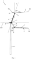
- Figs. 2-4 are side views of the wind turbine 1 of Fig. 1 with the wind turbine blades 5 at three different pivot angles.
- the pivot angle can vary between a maximum pivot angle, defining a maximum rotor diameter, as shown in Fig. 2 , and a minimum pivot angle, defining a minimum rotor diameter, as shown in Fig. 4 .
- Fig. 3 shows the wind turbine blades 5 at an intermediate pivot angle between the maximum and minimum rotor diameter, i.e., maximum and minimum pivot angle.
- Fig. 2 the wind turbine blade 5 is arranged in a position defining maximum pivot angle, and thereby maximum rotor diameter. Accordingly, the inner blade part 8 is arranged immediately adjacent to the blade carrying structure 4. The figure shows a bend defined by the angle, ⁇ , between the inner blade part 8 and the outer blade part 7. Fig. 2 also shows the nacelle 9.
- Fig. 3 shows the wind turbine 1 with the wind turbine blades 5 at a pivot angle between minimum and maximum pivot angle, and a rotor diameter which is decreased compared to the maximum rotor diameter illustrated in Fig. 2 . It can be seen that the inner blade part 8 has moved away from the blade carrying structure 4, and that the inner tip 5a has been moved closer to the tower 2. Fig.
- Fig. 4 shows the wind turbine 1 with the wind turbine blades 5 pivoted such that they define a minimum pivot angle and therefore minimum rotor diameter. Accordingly, the inner blade part 8 has been moved further away from the blade carrying structure 4 and the inner tip 5a has been moved closer to the tower 2.
- Each hinge 6 is associated with a hinge axis which in the depicted view is orthogonal to the plane of the paper.
- Fig. 4 furthermore indicates a coning angle, ⁇ , of the coning angle of the blade carrying structure, which in the depicted embodiment comprises an arm 4 which makes an angle with respect to a plane being orthogonal to the rotor axis 321 wherein said angle is corresponding to the coning angle, ⁇ .
- Fig. 5 shows the wind turbine 1 with the rotor rotated half a revolution ( ⁇ or 180°) so that on blade is pointed vertically downwards and is depicted at tower passage.
- Fig. 5 shows a horizontal (where a horizontal plane is indicated by dashed line 522) distance L 0 from the tower 2 at a vertical position defined by a position of the hinge 6 at tower passage (where the point of connection between the blade carrying structure and the hub 3 is defined by the point of connection between the arm 4 and the hub 3).
- Fig. 5 also indicates the second length L 2 , which is larger than the horizontal distance L 0 .
- FIG. 5 also indicates an (upper) horizontal distance L 5 from the tower 2 at a vertical position (as indicated by dashed line 524) at which the tower is abutting the nacelle to a point of connection between the blade carrying structure and the hub, which in the embodiment depicted in Fig. 5 is smaller (due to the conical shape of the tower with a decreasing diameter in an upwards directions) than the (lower) horizontal distance (L 0 ).
- the (upper) horizontal distance L 5 is larger than the (lower) horizontal distance L 0 , such as a horizontal distance between the upper part of the tower and the connection between the hub and the hub arm (roughly the "overhang") being smaller than a horizontal distance between the hinge and the tower at tower passage.
- This may be realized, e.g., by tilting the tower (such as tilting the tower in fig. 5 so that the upper portion moves towards the right hand side) and/or by arranging the tower with a cross-section being dependent on the vertical position (such as with decreasing diameter in a downwards direction and/or an hour-glass shape with a waist at or close to a vertical position of the hinge during tower passage).
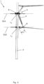
- Fig. 6 shows a downwind wind turbine 601, which is similar to the wind turbine 1 of Figs. 1-5 , except that the wind turbine 601 of Fig. 6 also features a tilt angle, ⁇ , of the rotor axis which is larger than zero, where the tilt angle, ⁇ , is indicated as the angle between the rotor axis 621 and a horizontal plane as indicated by dashed line 623.
- the larger than zero tilt angle, ⁇ implies that the rotor axis is pointing upwards in a direction (as indicated by arrow 625), which direction is identical to a wind direction for the downwind wind turbine 601, away from the tower axis and/or the nacelle 609 and towards the hub 603 (such as towards a point on the hub being traversed by the rotor axis and being most distantly placed with respect to the nacelle), which in Fig. 6 is shown as a direction from left to right due to the hub 603 being placed in Fig. 6 on the right hand side of the nacelle 609. Fig.
- FIG. 6 also shows a horizontal (where a horizontal plane is indicated by dashed line 622) distance L 0 from the tower 2 at a vertical position defined by a position of the hinge 606 at tower passage (where the point of connection between the blade carrying structure and the hub is defined by the point of connection between the arm 604 and the hub 603).
- Fig. 6 also indicates the second length L 2 , which is larger than the horizontal distance L 0 .
- Fig. 7 shows a wind turbine 701, which is similar to the wind turbine 1 of Figs. 1-5 , except that the wind turbine 701 of Fig. 7 also features a biasing mechanism 710 in the form of a hydraulic motor mounted on the arm 704 and arranged to exerted a pulling force (in a direction as indicated by the arrow 712) at a point of attack at a distal end of the inner portion 708, which yields a torque, ⁇ , around the hinge 706, which in turn goes to rotate the wind turbine blade 705 in a counter-clockwise (in the depicted view) direction around the hinge 706.
- a similar biasing mechanism is arranged in connection with each wind turbine blade (albeit for clarity only shown in the figure for on wind turbine blade).
- a wind turbine comprising:
- a horizontal distance between on the one side the point of connection between the blade carrying structure and the hub and on the other side the tower is larger at the lower vertical position where the hinge passes by the tower at tower passage (typically the lowest position of the hinge during rotor rotation) than at the upper position where the tower abuts the nacelle (typically a top part of the tower).
- the horizontal distance between said point of connection and the tower may thus be increasing in a downwards direction (which may be realized by arranging an axis of the tower to present a non-zero angle with respect to a vertical line and/or arranging an outer shape of the tower facing a plane traced by the hinge during rotation so that a distance to this plane increases in a downwards direction).
- L 2 second length
- at least a part of the tower is mounted on a foundation via a yaw system.
Landscapes
- Engineering & Computer Science (AREA)
- Life Sciences & Earth Sciences (AREA)
- Sustainable Development (AREA)
- Sustainable Energy (AREA)
- Chemical & Material Sciences (AREA)
- Combustion & Propulsion (AREA)
- Mechanical Engineering (AREA)
- General Engineering & Computer Science (AREA)
- Physics & Mathematics (AREA)
- Fluid Mechanics (AREA)
- Wind Motors (AREA)
Claims (15)
- Éolienne, comprenant :- une tour,- une nacelle montée sur la tour,- un générateur,- un moyeu monté rotatif sur la nacelle,- une structure de support de pales reliée au moyeu,- une ou plusieurs pales d'éolienne reliées à la structure de support de pales via une articulation, chaque pale d'éolienne étant ainsi agencée pour effectuer des mouvements de pivotement par rapport à la structure de support de pales entre un angle de pivotement minimum et un angle de pivotement maximum, chaque pale d'éolienne s'étendant entre une pointe extérieure et une pointe intérieure,dans laquelle chaque pale d'éolienne présente :- une partie extérieure s'étendant entre l'articulation et la pointe extérieure et ayant une première longueur (L1), et- une partie intérieure s'étendant entre l'articulation et la pointe intérieure et ayant une seconde longueur (L2),dans laquelle un angle de conicité de la structure de support de pales est supérieur à zéro et/ou un angle d'inclinaison de l'axe de rotor est supérieur à zéro,et dans laquelle une distance horizontale (La) depuis- la tour à une position verticale définie par une position de l'articulation au niveau du passage de la tour jusqu'à- un point de raccordement entre la structure de support de pales et le moyeu est inférieure ou égale à la seconde longueur (L2).
- Éolienne selon la revendication 1, dans laquelle l'angle d'inclinaison se situe dans l'intervalle [0,1° ; 20,0°].
- Éolienne selon l'une quelconque des revendications 1 ou 2, dans laquelle l'angle de conicité se situe dans l'intervalle [0,1° ; 45,0°].
- Éolienne selon l'une quelconque des revendications précédentes, comprenant en outre un mécanisme de sollicitation agencé pour appliquer une force de sollicitation aux une ou plusieurs pales d'éolienne qui sollicite les une ou plusieurs pales d'éolienne vers l'angle de pivotement maximum et/ou l'angle de pivotement minimum.
- Éolienne selon la revendication 4, dans laquelle la force de sollicitation est appliquée comme une force agissant sur la partie intérieure de chacune des une ou plusieurs pales d'éolienne.
- Éolienne selon l'une quelconque des revendications précédentes, dans laquelle une distance entre un axe de l'articulation et l'axe de rotor est supérieure ou égale à la seconde longueur (L2).
- Éolienne selon l'une quelconque des revendications précédentes, dans laquelle la nacelle est montée sur la tour par l'intermédiaire d'un système de lacet.
- Éolienne selon l'une quelconque des revendications précédentes, dans laquelle la structure de support de pales comprend un ou plusieurs bras, chaque pale d'éolienne étant montée sur un des bras.
- Éolienne selon la revendication 8, dans laquelle un axe de chaque bras forme un angle par rapport à un plan perpendiculaire à l'axe de rotor, dans laquelle ledit angle correspond à l'angle de conicité.
- Éolienne selon l'une quelconque des revendications précédentes, dans laquelle la partie de pale extérieure s'étend depuis la région de l'articulation dans une première direction et la partie de pale intérieure s'étend depuis la région de l'articulation dans une seconde direction, et dans laquelle la première direction et la seconde direction forment entre elles un angle, α, avec 0°<α<90°.
- Éolienne selon l'une quelconque des revendications précédentes, dans laquelle l'éolienne est une éolienne sous le vent.
- Éolienne selon l'une quelconque des revendications précédentes, dans laquelle un intervalle angulaire entre un angle de pivotement minimum et un angle de pivotement maximum comprend un angle auquel une distance entre la partie intérieure d'au moins une pale parmi les une ou plusieurs pales et la tour est un minimum global.
- Utilisation d'une éolienne selon l'une quelconque des revendications précédentes pour produire une puissance électrique.
- Procédé de commande d'une éolienne selon l'une quelconque des revendications 1-12, ledit procédé comprenant le pivotement d'au moins une pale parmi les une ou plusieurs pales.
- Procédé selon la revendication 14, dans lequel le procédé comprend le pivotement de la au moins une pale selon un angle de pivotement auquel angle de pivotement une distance entre la partie intérieure d'au moins une pale parmi les une ou plusieurs pales et la tour est un minimum global.
Applications Claiming Priority (2)
| Application Number | Priority Date | Filing Date | Title |
|---|---|---|---|
| DKPA201970692 | 2019-11-12 | ||
| PCT/DK2020/050305 WO2021093924A1 (fr) | 2019-11-12 | 2020-11-10 | Éolienne à pales articulées dotée d'un axe incliné et/ou d'un rotor conique |
Publications (2)
| Publication Number | Publication Date |
|---|---|
| EP4058670A1 EP4058670A1 (fr) | 2022-09-21 |
| EP4058670B1 true EP4058670B1 (fr) | 2023-06-14 |
Family
ID=73497491
Family Applications (1)
| Application Number | Title | Priority Date | Filing Date |
|---|---|---|---|
| EP20810866.2A Active EP4058670B1 (fr) | 2019-11-12 | 2020-11-10 | Éolienne à pâles articulées dotée d'un axe incliné et/ou d'un rotor conique |
Country Status (4)
| Country | Link |
|---|---|
| US (1) | US11898534B2 (fr) |
| EP (1) | EP4058670B1 (fr) |
| CN (1) | CN114945745A (fr) |
| WO (1) | WO2021093924A1 (fr) |
Families Citing this family (1)
| Publication number | Priority date | Publication date | Assignee | Title |
|---|---|---|---|---|
| WO2021093924A1 (fr) | 2019-11-12 | 2021-05-20 | Vestas Wind Systems A/S | Éolienne à pales articulées dotée d'un axe incliné et/ou d'un rotor conique |
Family Cites Families (23)
| Publication number | Priority date | Publication date | Assignee | Title |
|---|---|---|---|---|
| US400230A (en) | 1889-03-26 | Windmill | ||
| US279194A (en) | 1883-06-12 | Windmill | ||
| US612464A (en) | 1898-10-18 | Windmill | ||
| US173676A (en) | 1876-02-15 | Improvement in windmills | ||
| US1178729A (en) * | 1914-08-17 | 1916-04-11 | Duston Kemble | Wind-wheel. |
| DE2737767C2 (de) * | 1977-08-22 | 1979-05-17 | Ulrich Prof. Dr.-Ing. 7312 Kirchheim Huetter | Windkraftanlage |
| US4632637A (en) * | 1981-06-04 | 1986-12-30 | Analytics, Inc. | Wind turbine |
| US4533297A (en) * | 1982-09-15 | 1985-08-06 | Bassett David A | Rotor system for horizontal axis wind turbines |
| ES2179785B1 (es) * | 2001-06-12 | 2006-10-16 | Ivan Lahuerta Antoune | Turbina eolica autotimonante. |
| DK200500899A (da) * | 2005-06-17 | 2006-12-18 | Lm Glasfiber As | Vinge med hængslet vingetip |
| US7828523B2 (en) * | 2007-03-27 | 2010-11-09 | General Electric Company | Rotor blade for a wind turbine having a variable dimension |
| US20090167023A1 (en) | 2007-12-27 | 2009-07-02 | Jacob Johannes Nies | Forward leaning tower top section |
| JP2010071277A (ja) | 2008-09-19 | 2010-04-02 | Tamotsu Shimauchi | 復動格納式風力発電機 |
| US7946826B1 (en) | 2010-07-16 | 2011-05-24 | General Electric Company | Wind turbine rotor blade with a suction side winglet |
| GB2482661A (en) * | 2010-07-26 | 2012-02-15 | Vestas Wind Sys As | Upwind wind turbine with tower-mounted air pressure sensors |
| US8029241B2 (en) * | 2010-09-15 | 2011-10-04 | General Electric Company | Wind turbine rotor blade with aerodynamic winglet |
| US20120027595A1 (en) * | 2011-08-09 | 2012-02-02 | General Electric Company | Pitchable winglet for a wind turbine rotor blade |
| WO2013083130A1 (fr) * | 2011-12-09 | 2013-06-13 | Vestas Wind Systems A/S | Turbine éolienne comprenant des pales à ailette latérale d'aspiration |
| EP2795106B1 (fr) * | 2011-12-21 | 2019-03-06 | Vestas Wind Systems A/S | Pale de rotor de turbine éolienne avec un angle de cône et méthode de fabrication d'une pale de rotor de turbine éolienne |
| WO2016203557A1 (fr) | 2015-06-17 | 2016-12-22 | 株式会社日立製作所 | Dispositif de génération d'énergie éolienne |
| US10865768B2 (en) * | 2017-02-14 | 2020-12-15 | Blok SHAIKENOV | Wind wheel with blade elbow bend |
| CN108266312A (zh) * | 2018-01-16 | 2018-07-10 | 马可颖 | 一种风力机涡流发生器调节机构 |
| WO2021093924A1 (fr) | 2019-11-12 | 2021-05-20 | Vestas Wind Systems A/S | Éolienne à pales articulées dotée d'un axe incliné et/ou d'un rotor conique |
-
2020
- 2020-11-10 WO PCT/DK2020/050305 patent/WO2021093924A1/fr not_active Ceased
- 2020-11-10 EP EP20810866.2A patent/EP4058670B1/fr active Active
- 2020-11-10 CN CN202080091398.8A patent/CN114945745A/zh active Pending
- 2020-11-10 US US17/776,206 patent/US11898534B2/en active Active
Also Published As
| Publication number | Publication date |
|---|---|
| US11898534B2 (en) | 2024-02-13 |
| CN114945745A (zh) | 2022-08-26 |
| US20220381222A1 (en) | 2022-12-01 |
| WO2021093924A1 (fr) | 2021-05-20 |
| EP4058670A1 (fr) | 2022-09-21 |
Similar Documents
| Publication | Publication Date | Title |
|---|---|---|
| EP3807520B1 (fr) | Une éolienne dont les pales sont articulées à une position intermédiaire | |
| US8333564B2 (en) | Vertical axis wind turbine airfoil | |
| US5584655A (en) | Rotor device and control for wind turbine | |
| CN102536629B (zh) | 风力涡轮机、用于风力涡轮机的气动组件及其组装方法 | |
| CN106762465B (zh) | 风力发电机组 | |
| WO1996020343A9 (fr) | Rotor et commande pour eolienne | |
| US20120141267A1 (en) | Wind turbine blade automatic pitch control using centrifugal force | |
| EP3807522B1 (fr) | Eolienne à pales articulées ayant une position charnière entre l'extrémité interne et l'extrémité externe des pales | |
| EP4058670B1 (fr) | Éolienne à pâles articulées dotée d'un axe incliné et/ou d'un rotor conique | |
| CN112534132B (zh) | 具有铰接叶片的风力涡轮机中的噪声降低 | |
| EP3807521B1 (fr) | Une eolienne avec des pales de rotor pivotantes, un fil et un mécanisme de déverrouillage pour l'arreter | |
| US11473559B2 (en) | Hinged wind turbine blade defining an angle in a flap-wise direction | |
| WO2011039777A2 (fr) | Système de commande de l'angle de cône et de l'angle de calage d'un ensemble pales de rotor d'une éolienne | |
| WO2021129907A1 (fr) | Procédé de commande de moment d'inclinaison d'une éolienne à pales d'éolienne articulées | |
| WO2021043381A1 (fr) | Parc éolien comprenant des éoliennes à pales articulées | |
| WO2024193781A1 (fr) | Éolienne à pas variable | |
| US20240229765A1 (en) | Wind turbine | |
| WO2021129906A1 (fr) | Procédé de commande de lacet d'éolienne dotée de pales d'éolienne articulées | |
| US20240077057A1 (en) | A method for starting a wind turbine with hinged wind turbine blades |
Legal Events
| Date | Code | Title | Description |
|---|---|---|---|
| STAA | Information on the status of an ep patent application or granted ep patent |
Free format text: STATUS: UNKNOWN |
|
| STAA | Information on the status of an ep patent application or granted ep patent |
Free format text: STATUS: THE INTERNATIONAL PUBLICATION HAS BEEN MADE |
|
| PUAI | Public reference made under article 153(3) epc to a published international application that has entered the european phase |
Free format text: ORIGINAL CODE: 0009012 |
|
| STAA | Information on the status of an ep patent application or granted ep patent |
Free format text: STATUS: REQUEST FOR EXAMINATION WAS MADE |
|
| 17P | Request for examination filed |
Effective date: 20220530 |
|
| AK | Designated contracting states |
Kind code of ref document: A1 Designated state(s): AL AT BE BG CH CY CZ DE DK EE ES FI FR GB GR HR HU IE IS IT LI LT LU LV MC MK MT NL NO PL PT RO RS SE SI SK SM TR |
|
| DAV | Request for validation of the european patent (deleted) | ||
| DAX | Request for extension of the european patent (deleted) | ||
| GRAP | Despatch of communication of intention to grant a patent |
Free format text: ORIGINAL CODE: EPIDOSNIGR1 |
|
| STAA | Information on the status of an ep patent application or granted ep patent |
Free format text: STATUS: GRANT OF PATENT IS INTENDED |
|
| INTG | Intention to grant announced |
Effective date: 20230322 |
|
| GRAS | Grant fee paid |
Free format text: ORIGINAL CODE: EPIDOSNIGR3 |
|
| GRAA | (expected) grant |
Free format text: ORIGINAL CODE: 0009210 |
|
| STAA | Information on the status of an ep patent application or granted ep patent |
Free format text: STATUS: THE PATENT HAS BEEN GRANTED |
|
| AK | Designated contracting states |
Kind code of ref document: B1 Designated state(s): AL AT BE BG CH CY CZ DE DK EE ES FI FR GB GR HR HU IE IS IT LI LT LU LV MC MK MT NL NO PL PT RO RS SE SI SK SM TR |
|
| REG | Reference to a national code |
Ref country code: CH Ref legal event code: EP |
|
| REG | Reference to a national code |
Ref country code: DE Ref legal event code: R096 Ref document number: 602020012596 Country of ref document: DE |
|
| REG | Reference to a national code |
Ref country code: AT Ref legal event code: REF Ref document number: 1579407 Country of ref document: AT Kind code of ref document: T Effective date: 20230715 |
|
| P01 | Opt-out of the competence of the unified patent court (upc) registered |
Effective date: 20230707 |
|
| REG | Reference to a national code |
Ref country code: LT Ref legal event code: MG9D |
|
| REG | Reference to a national code |
Ref country code: NL Ref legal event code: MP Effective date: 20230614 |
|
| PG25 | Lapsed in a contracting state [announced via postgrant information from national office to epo] |
Ref country code: SE Free format text: LAPSE BECAUSE OF FAILURE TO SUBMIT A TRANSLATION OF THE DESCRIPTION OR TO PAY THE FEE WITHIN THE PRESCRIBED TIME-LIMIT Effective date: 20230614 Ref country code: NO Free format text: LAPSE BECAUSE OF FAILURE TO SUBMIT A TRANSLATION OF THE DESCRIPTION OR TO PAY THE FEE WITHIN THE PRESCRIBED TIME-LIMIT Effective date: 20230914 Ref country code: ES Free format text: LAPSE BECAUSE OF FAILURE TO SUBMIT A TRANSLATION OF THE DESCRIPTION OR TO PAY THE FEE WITHIN THE PRESCRIBED TIME-LIMIT Effective date: 20230614 |
|
| REG | Reference to a national code |
Ref country code: AT Ref legal event code: MK05 Ref document number: 1579407 Country of ref document: AT Kind code of ref document: T Effective date: 20230614 |
|
| PG25 | Lapsed in a contracting state [announced via postgrant information from national office to epo] |
Ref country code: RS Free format text: LAPSE BECAUSE OF FAILURE TO SUBMIT A TRANSLATION OF THE DESCRIPTION OR TO PAY THE FEE WITHIN THE PRESCRIBED TIME-LIMIT Effective date: 20230614 Ref country code: NL Free format text: LAPSE BECAUSE OF FAILURE TO SUBMIT A TRANSLATION OF THE DESCRIPTION OR TO PAY THE FEE WITHIN THE PRESCRIBED TIME-LIMIT Effective date: 20230614 Ref country code: LV Free format text: LAPSE BECAUSE OF FAILURE TO SUBMIT A TRANSLATION OF THE DESCRIPTION OR TO PAY THE FEE WITHIN THE PRESCRIBED TIME-LIMIT Effective date: 20230614 Ref country code: LT Free format text: LAPSE BECAUSE OF FAILURE TO SUBMIT A TRANSLATION OF THE DESCRIPTION OR TO PAY THE FEE WITHIN THE PRESCRIBED TIME-LIMIT Effective date: 20230614 Ref country code: HR Free format text: LAPSE BECAUSE OF FAILURE TO SUBMIT A TRANSLATION OF THE DESCRIPTION OR TO PAY THE FEE WITHIN THE PRESCRIBED TIME-LIMIT Effective date: 20230614 Ref country code: GR Free format text: LAPSE BECAUSE OF FAILURE TO SUBMIT A TRANSLATION OF THE DESCRIPTION OR TO PAY THE FEE WITHIN THE PRESCRIBED TIME-LIMIT Effective date: 20230915 |
|
| PG25 | Lapsed in a contracting state [announced via postgrant information from national office to epo] |
Ref country code: FI Free format text: LAPSE BECAUSE OF FAILURE TO SUBMIT A TRANSLATION OF THE DESCRIPTION OR TO PAY THE FEE WITHIN THE PRESCRIBED TIME-LIMIT Effective date: 20230614 |
|
| PG25 | Lapsed in a contracting state [announced via postgrant information from national office to epo] |
Ref country code: SK Free format text: LAPSE BECAUSE OF FAILURE TO SUBMIT A TRANSLATION OF THE DESCRIPTION OR TO PAY THE FEE WITHIN THE PRESCRIBED TIME-LIMIT Effective date: 20230614 |
|
| PG25 | Lapsed in a contracting state [announced via postgrant information from national office to epo] |
Ref country code: IS Free format text: LAPSE BECAUSE OF FAILURE TO SUBMIT A TRANSLATION OF THE DESCRIPTION OR TO PAY THE FEE WITHIN THE PRESCRIBED TIME-LIMIT Effective date: 20231014 |
|
| PG25 | Lapsed in a contracting state [announced via postgrant information from national office to epo] |
Ref country code: SM Free format text: LAPSE BECAUSE OF FAILURE TO SUBMIT A TRANSLATION OF THE DESCRIPTION OR TO PAY THE FEE WITHIN THE PRESCRIBED TIME-LIMIT Effective date: 20230614 Ref country code: SK Free format text: LAPSE BECAUSE OF FAILURE TO SUBMIT A TRANSLATION OF THE DESCRIPTION OR TO PAY THE FEE WITHIN THE PRESCRIBED TIME-LIMIT Effective date: 20230614 Ref country code: RO Free format text: LAPSE BECAUSE OF FAILURE TO SUBMIT A TRANSLATION OF THE DESCRIPTION OR TO PAY THE FEE WITHIN THE PRESCRIBED TIME-LIMIT Effective date: 20230614 Ref country code: PT Free format text: LAPSE BECAUSE OF FAILURE TO SUBMIT A TRANSLATION OF THE DESCRIPTION OR TO PAY THE FEE WITHIN THE PRESCRIBED TIME-LIMIT Effective date: 20231016 Ref country code: IS Free format text: LAPSE BECAUSE OF FAILURE TO SUBMIT A TRANSLATION OF THE DESCRIPTION OR TO PAY THE FEE WITHIN THE PRESCRIBED TIME-LIMIT Effective date: 20231014 Ref country code: EE Free format text: LAPSE BECAUSE OF FAILURE TO SUBMIT A TRANSLATION OF THE DESCRIPTION OR TO PAY THE FEE WITHIN THE PRESCRIBED TIME-LIMIT Effective date: 20230614 Ref country code: CZ Free format text: LAPSE BECAUSE OF FAILURE TO SUBMIT A TRANSLATION OF THE DESCRIPTION OR TO PAY THE FEE WITHIN THE PRESCRIBED TIME-LIMIT Effective date: 20230614 Ref country code: AT Free format text: LAPSE BECAUSE OF FAILURE TO SUBMIT A TRANSLATION OF THE DESCRIPTION OR TO PAY THE FEE WITHIN THE PRESCRIBED TIME-LIMIT Effective date: 20230614 |
|
| PG25 | Lapsed in a contracting state [announced via postgrant information from national office to epo] |
Ref country code: PL Free format text: LAPSE BECAUSE OF FAILURE TO SUBMIT A TRANSLATION OF THE DESCRIPTION OR TO PAY THE FEE WITHIN THE PRESCRIBED TIME-LIMIT Effective date: 20230614 |
|
| REG | Reference to a national code |
Ref country code: DE Ref legal event code: R097 Ref document number: 602020012596 Country of ref document: DE |
|
| PLBE | No opposition filed within time limit |
Free format text: ORIGINAL CODE: 0009261 |
|
| STAA | Information on the status of an ep patent application or granted ep patent |
Free format text: STATUS: NO OPPOSITION FILED WITHIN TIME LIMIT |
|
| PG25 | Lapsed in a contracting state [announced via postgrant information from national office to epo] |
Ref country code: DK Free format text: LAPSE BECAUSE OF FAILURE TO SUBMIT A TRANSLATION OF THE DESCRIPTION OR TO PAY THE FEE WITHIN THE PRESCRIBED TIME-LIMIT Effective date: 20230614 |
|
| PG25 | Lapsed in a contracting state [announced via postgrant information from national office to epo] |
Ref country code: SI Free format text: LAPSE BECAUSE OF FAILURE TO SUBMIT A TRANSLATION OF THE DESCRIPTION OR TO PAY THE FEE WITHIN THE PRESCRIBED TIME-LIMIT Effective date: 20230614 |
|
| 26N | No opposition filed |
Effective date: 20240315 |
|
| PG25 | Lapsed in a contracting state [announced via postgrant information from national office to epo] |
Ref country code: SI Free format text: LAPSE BECAUSE OF FAILURE TO SUBMIT A TRANSLATION OF THE DESCRIPTION OR TO PAY THE FEE WITHIN THE PRESCRIBED TIME-LIMIT Effective date: 20230614 Ref country code: IT Free format text: LAPSE BECAUSE OF FAILURE TO SUBMIT A TRANSLATION OF THE DESCRIPTION OR TO PAY THE FEE WITHIN THE PRESCRIBED TIME-LIMIT Effective date: 20230614 |
|
| REG | Reference to a national code |
Ref country code: CH Ref legal event code: PL |
|
| PG25 | Lapsed in a contracting state [announced via postgrant information from national office to epo] |
Ref country code: MC Free format text: LAPSE BECAUSE OF FAILURE TO SUBMIT A TRANSLATION OF THE DESCRIPTION OR TO PAY THE FEE WITHIN THE PRESCRIBED TIME-LIMIT Effective date: 20230614 |
|
| PG25 | Lapsed in a contracting state [announced via postgrant information from national office to epo] |
Ref country code: LU Free format text: LAPSE BECAUSE OF NON-PAYMENT OF DUE FEES Effective date: 20231110 |
|
| PG25 | Lapsed in a contracting state [announced via postgrant information from national office to epo] |
Ref country code: CH Free format text: LAPSE BECAUSE OF NON-PAYMENT OF DUE FEES Effective date: 20231130 |
|
| PG25 | Lapsed in a contracting state [announced via postgrant information from national office to epo] |
Ref country code: MC Free format text: LAPSE BECAUSE OF FAILURE TO SUBMIT A TRANSLATION OF THE DESCRIPTION OR TO PAY THE FEE WITHIN THE PRESCRIBED TIME-LIMIT Effective date: 20230614 Ref country code: LU Free format text: LAPSE BECAUSE OF NON-PAYMENT OF DUE FEES Effective date: 20231110 Ref country code: CH Free format text: LAPSE BECAUSE OF NON-PAYMENT OF DUE FEES Effective date: 20231130 |
|
| REG | Reference to a national code |
Ref country code: BE Ref legal event code: MM Effective date: 20231130 |
|
| REG | Reference to a national code |
Ref country code: IE Ref legal event code: MM4A |
|
| PG25 | Lapsed in a contracting state [announced via postgrant information from national office to epo] |
Ref country code: IE Free format text: LAPSE BECAUSE OF NON-PAYMENT OF DUE FEES Effective date: 20231110 |
|
| PG25 | Lapsed in a contracting state [announced via postgrant information from national office to epo] |
Ref country code: BE Free format text: LAPSE BECAUSE OF NON-PAYMENT OF DUE FEES Effective date: 20231130 |
|
| PG25 | Lapsed in a contracting state [announced via postgrant information from national office to epo] |
Ref country code: IE Free format text: LAPSE BECAUSE OF NON-PAYMENT OF DUE FEES Effective date: 20231110 Ref country code: BE Free format text: LAPSE BECAUSE OF NON-PAYMENT OF DUE FEES Effective date: 20231130 |
|
| PG25 | Lapsed in a contracting state [announced via postgrant information from national office to epo] |
Ref country code: BG Free format text: LAPSE BECAUSE OF FAILURE TO SUBMIT A TRANSLATION OF THE DESCRIPTION OR TO PAY THE FEE WITHIN THE PRESCRIBED TIME-LIMIT Effective date: 20230614 |
|
| PG25 | Lapsed in a contracting state [announced via postgrant information from national office to epo] |
Ref country code: BG Free format text: LAPSE BECAUSE OF FAILURE TO SUBMIT A TRANSLATION OF THE DESCRIPTION OR TO PAY THE FEE WITHIN THE PRESCRIBED TIME-LIMIT Effective date: 20230614 |
|
| PG25 | Lapsed in a contracting state [announced via postgrant information from national office to epo] |
Ref country code: CY Free format text: LAPSE BECAUSE OF FAILURE TO SUBMIT A TRANSLATION OF THE DESCRIPTION OR TO PAY THE FEE WITHIN THE PRESCRIBED TIME-LIMIT; INVALID AB INITIO Effective date: 20201110 |
|
| PG25 | Lapsed in a contracting state [announced via postgrant information from national office to epo] |
Ref country code: HU Free format text: LAPSE BECAUSE OF FAILURE TO SUBMIT A TRANSLATION OF THE DESCRIPTION OR TO PAY THE FEE WITHIN THE PRESCRIBED TIME-LIMIT; INVALID AB INITIO Effective date: 20201110 |
|
| PG25 | Lapsed in a contracting state [announced via postgrant information from national office to epo] |
Ref country code: TR Free format text: LAPSE BECAUSE OF FAILURE TO SUBMIT A TRANSLATION OF THE DESCRIPTION OR TO PAY THE FEE WITHIN THE PRESCRIBED TIME-LIMIT Effective date: 20230614 |
|
| PGFP | Annual fee paid to national office [announced via postgrant information from national office to epo] |
Ref country code: DE Payment date: 20251126 Year of fee payment: 6 |
|
| PGFP | Annual fee paid to national office [announced via postgrant information from national office to epo] |
Ref country code: GB Payment date: 20251125 Year of fee payment: 6 |
|
| PGFP | Annual fee paid to national office [announced via postgrant information from national office to epo] |
Ref country code: FR Payment date: 20251124 Year of fee payment: 6 |