EP4057915B1 - Embolievorrichtung zum verschliessen von körperlumen - Google Patents
Embolievorrichtung zum verschliessen von körperlumen Download PDFInfo
- Publication number
- EP4057915B1 EP4057915B1 EP20817145.4A EP20817145A EP4057915B1 EP 4057915 B1 EP4057915 B1 EP 4057915B1 EP 20817145 A EP20817145 A EP 20817145A EP 4057915 B1 EP4057915 B1 EP 4057915B1
- Authority
- EP
- European Patent Office
- Prior art keywords
- segment
- elongated member
- embolic device
- body temperature
- length
- Prior art date
- Legal status (The legal status is an assumption and is not a legal conclusion. Google has not performed a legal analysis and makes no representation as to the accuracy of the status listed.)
- Active
Links
Images



Classifications
-
- A—HUMAN NECESSITIES
- A61—MEDICAL OR VETERINARY SCIENCE; HYGIENE
- A61B—DIAGNOSIS; SURGERY; IDENTIFICATION
- A61B17/00—Surgical instruments, devices or methods
- A61B17/12—Surgical instruments, devices or methods for ligaturing or otherwise compressing tubular parts of the body, e.g. blood vessels or umbilical cord
- A61B17/12022—Occluding by internal devices, e.g. balloons or releasable wires
- A61B17/12131—Occluding by internal devices, e.g. balloons or releasable wires characterised by the type of occluding device
- A61B17/1214—Coils or wires
- A61B17/12145—Coils or wires having a pre-set deployed three-dimensional shape
-
- A—HUMAN NECESSITIES
- A61—MEDICAL OR VETERINARY SCIENCE; HYGIENE
- A61B—DIAGNOSIS; SURGERY; IDENTIFICATION
- A61B17/00—Surgical instruments, devices or methods
- A61B17/12—Surgical instruments, devices or methods for ligaturing or otherwise compressing tubular parts of the body, e.g. blood vessels or umbilical cord
- A61B17/12022—Occluding by internal devices, e.g. balloons or releasable wires
- A61B17/12099—Occluding by internal devices, e.g. balloons or releasable wires characterised by the location of the occluder
- A61B17/12109—Occluding by internal devices, e.g. balloons or releasable wires characterised by the location of the occluder in a blood vessel
- A61B17/12113—Occluding by internal devices, e.g. balloons or releasable wires characterised by the location of the occluder in a blood vessel within an aneurysm
-
- A—HUMAN NECESSITIES
- A61—MEDICAL OR VETERINARY SCIENCE; HYGIENE
- A61B—DIAGNOSIS; SURGERY; IDENTIFICATION
- A61B17/00—Surgical instruments, devices or methods
- A61B17/12—Surgical instruments, devices or methods for ligaturing or otherwise compressing tubular parts of the body, e.g. blood vessels or umbilical cord
- A61B17/12022—Occluding by internal devices, e.g. balloons or releasable wires
- A61B17/12131—Occluding by internal devices, e.g. balloons or releasable wires characterised by the type of occluding device
- A61B17/12168—Occluding by internal devices, e.g. balloons or releasable wires characterised by the type of occluding device having a mesh structure
- A61B17/12172—Occluding by internal devices, e.g. balloons or releasable wires characterised by the type of occluding device having a mesh structure having a pre-set deployed three-dimensional shape
-
- A—HUMAN NECESSITIES
- A61—MEDICAL OR VETERINARY SCIENCE; HYGIENE
- A61B—DIAGNOSIS; SURGERY; IDENTIFICATION
- A61B17/00—Surgical instruments, devices or methods
- A61B17/00234—Surgical instruments, devices or methods for minimally invasive surgery
- A61B2017/00292—Surgical instruments, devices or methods for minimally invasive surgery mounted on or guided by flexible, e.g. catheter-like, means
- A61B2017/003—Steerable
- A61B2017/00318—Steering mechanisms
- A61B2017/00323—Cables or rods
-
- A—HUMAN NECESSITIES
- A61—MEDICAL OR VETERINARY SCIENCE; HYGIENE
- A61B—DIAGNOSIS; SURGERY; IDENTIFICATION
- A61B17/00—Surgical instruments, devices or methods
- A61B2017/00831—Material properties
- A61B2017/00867—Material properties shape memory effect
-
- A—HUMAN NECESSITIES
- A61—MEDICAL OR VETERINARY SCIENCE; HYGIENE
- A61B—DIAGNOSIS; SURGERY; IDENTIFICATION
- A61B17/00—Surgical instruments, devices or methods
- A61B17/12—Surgical instruments, devices or methods for ligaturing or otherwise compressing tubular parts of the body, e.g. blood vessels or umbilical cord
- A61B17/12022—Occluding by internal devices, e.g. balloons or releasable wires
- A61B2017/1205—Introduction devices
Definitions
- the field of the disclosure relates to medical devices and methods for occluding body lumens, and more specifically, to medical devices and methods for occluding aneurysms.
- An aneurysm is a dilation of a blood vessel that poses a risk to health from the potential for rupture, clotting, or dissecting. Rupture of an aneurysm in the brain causes stroke, and rupture of an aneurysm in the abdomen causes shock. Cerebral aneurysms are usually detected in patients as the result of a seizure or hemorrhage and can result in significant morbidity or mortality.
- vaso-occlusion devices are surgical implements or implants that are placed within the vasculature of the human body, typically via a catheter, either to block the flow of blood through a vessel making up that portion of the vasculature through the formation of an embolus, or to form such an embolus within an aneurysm stemming from the vessel.
- the vaso-occlusion device when a vaso-occlusion device is being carried within the catheter, the vaso-occlusion device is elastically bent to conform with a profile of the catheter. This elastic bending of the vaso-occlusion device creates various pressure points against the inner surface of the catheter, which may be undesirable because it makes advancement of the vaso-occlusion device relative to the catheter harder. In some cases, increased axial force may need to be exerted in order to push the vaso-occlusion device distally. This increased axial force may sometimes cause premature buckling of the vaso-occlusion device inside the catheter.
- a vaso-occlusion device may assume a certain three-dimensional shape after it is deployed outside the catheter. If the deployed vaso-occlusion device is too stiff, it may not conform with a shape of the body cavity intended to be occluded by the vaso-occlusion device. On the other hand, if the deployed vaso-occlusion device is too flexible, then the vaso-occlusion device may not retain its shape, and may be unintentionally bent into an undesirable shape, rendering it incapable of occluding the body cavity.
- US 2006206140 A1 discloses an adjustable embolic aneurysm coil.
- the device can be adjusted within the body of a patient in a minimally invasive or non-invasive manner such as by applying energy percutaneously or external to the patient's body.
- the energy may include, for example, acoustic energy, radio frequency energy, light energy and magnetic energy.
- the size and/or shape of the embolic coil can be adjusted to provide optimal filling of the aneurysm.
- the devices include a shape memory material that is responsive to changes in temperature and/or exposure to a magnetic field. A material having enhanced absorption characteristics with regard to a desired heating energy may be used in order to facilitate heating and adjustment of the embolic coil.
- the invention is based on the task of providing an improved medical device of the type described above.
- the invention is set out in claims.
- an embolic device provided in claim 1.
- an embolic device for placement in a body lumen includes: an elongated member having a linear configuration when in room temperature, the elongated member being configured to form a first three-dimensional structure in response to body temperature; wherein the elongated member comprises a first segment, a second segment, and a third segment, the second segment being located between the first segment and the third segment; wherein the first segment and the third segment are configured to change their respective shapes in response to the body temperature; and wherein the second segment that is located between the first segment and the third segment has a shape that is independent of the body temperature.
- the first segment is configured to form a first portion of a loop
- the third segment is configured to form a second portion of the loop in response to the body temperature
- the first segment is configured to form a first loop
- the third segment is configured to form a second loop, in response to the body temperature.
- the first segment has a first length
- the second segment has a second length
- the third segment has a third length; and wherein the second length of the second segment is shorter than the first length of the first segment, and is also shorter than the third length of the third segment.
- the second length of the second segment that is between the first segment and the third segment is less than 50% of the first length of the first segment, and is also less than 50% of the third length of the third segment.
- the elongated member has a distal end and a proximal end opposite from the distal end, and wherein the embolic device further comprises a fourth segment that includes the proximal end; and wherein the fourth segment is martensitic when the fourth segment is in the room temperature, and is also martensitic when the fourth segment is in the body temperature.
- the first segment is martensitic when the first segment is in the room temperature, and is austenitic when the first segment is in the body temperature.
- the second segment is martensitic when the second segment is the room temperature, and is martensitic when the second segment is in the body temperature.
- the three-dimensional structure comprises a plurality of loops, and wherein the first segment, the second segment, and the third segment comprise respective portions of one of the loops.
- the elongated member further comprises a fourth segment, a fifth segment, and a sixth segment that comprise respective portions of another one of the loops; wherein the fifth segment is between the fourth segment and the sixth segment; wherein the fourth segment and the sixth segment are configured to change their respective shapes in response to the body temperature; and wherein the fifth segment that is located between the fourth segment and the sixth segment has a shape that is independent of the body temperature.
- an embolic device for placement in a body lumen includes: an elongated member having a linear configuration when in room temperature, the elongated member being configured to form a first three-dimensional structure in response to body temperature; wherein the elongated member comprises a first segment, a second segment, and a third segment, the second segment being located between the first segment and the third segment; wherein the first segment is martensitic when the first segment is in the room temperature, and is austenitic when the first segment is in the body temperature; and wherein the second segment is martensitic when the second segment is in the room temperature, and is also martensitic when the second segment is in the body temperature.
- the first segment is configured to form a first portion of a loop
- the third segment is configured to form a second portion of the loop, in response to the body temperature.
- the first segment has a first length
- the second segment has a second length
- the third segment has a third length; and wherein the second length of the second segment is shorter than the first length of the first segment, and is also shorter than the third length of the third segment.
- the second length of the second segment that is between the first segment and the third segment is less than 50% of the first length of the first segment, and is also less than 50% of the third length of the third segment.
- the elongated member has a distal end and a proximal end opposite from the distal end, and wherein the embolic device further comprises a fourth segment that includes the proximal end; and wherein the fourth segment is martensitic when in the room temperature, and is also martensitic when the fourth segment is the body temperature.
- the three-dimensional structure comprises a plurality of loops, and wherein the first segment, the second segment, and the third segment comprise respective portions of one of the loops.
- the elongated member further comprises a fourth segment, a fifth segment, and a sixth segment that comprise respective portions of another one of the loops; wherein the fifth segment is between the fourth segment and the sixth segment; wherein the fourth segment and the sixth segment are martensitic when the fourth segment and the sixth segment are in the room temperature, and are austenitic when the fourth segment and the sixth segment are in the body temperature; and wherein the fifth segment is martensitic when the fifth segment is in the room temperature, and is also martensitic when the fifth segment is in the body temperature.
- a method is provided of occluding a body lumen performed by an embolic device having an elongated member, the elongated member comprising a first segment, a second segment, and a third segment, wherein the second segment is between the first segment and the third segment, includes: undergoing a first shape change by the first segment of the elongated member in response to body temperature; undergoing a second shape change by the second segment of the elongated member in response to force; and undergoing a third shape change by the third segment of the elongated member in response to the body temperature.
- the first segment is martensitic when the first segment is in the room temperature, and is austenitic when the first segment is in the body temperature; and wherein the second segment is martensitic when the second segment is in the room temperature, and is also martensitic when the second segment is in the body temperature.
- the first segment forms a first portion of a loop
- the third segment forms a second portion of the loop, in response to the body temperature.
- the first segment forms a first loop
- the third segment forms a second loop, in response to the body temperature.
- the first segment has a first length
- the second segment has a second length
- the third segment has a third length; and wherein the second length of the second segment is shorter than the first length of the first segment, and is also shorter than the third length of the third segment.
- the second length of the second segment that is between the first segment and the third segment is less than 50% of the first length of the first segment, and is also less than 50% of the third length of the third segment.
- the elongated member has a distal end and a proximal end opposite from the distal end, and wherein the embolic device further comprises a fourth segment that includes the proximal end; and wherein the fourth segment is martensitic when in the room temperature, and is also martensitic when the fourth segment is the body temperature.
- the three-dimensional structure comprises a plurality of loops, and wherein the first segment, the second segment, and the third segment comprise respective portions of one of the loops.
- the elongated member further comprises a fourth segment, a fifth segment, and a sixth segment that comprise respective portions of another one of the loops; wherein the fifth segment is between the fourth segment and the sixth segment; wherein the fourth segment and the sixth segment are martensitic when the fourth segment and the sixth segment are in the room temperature, and are austenitic when the fourth segment and the sixth segment are in the body temperature; and wherein the fifth segment is martensitic when the fifth segment is in the room temperature, and is also martensitic when the fifth segment is in the body temperature.
- FIG. 1 illustrates a medical device 10 having a catheter 20 for delivering an embolic device 100 in a body lumen.
- the catheter 20 has a distal end 22, a proximal end 24, and a catheter body 26 extending between the distal end 22 and the proximal end 24.
- the embolic device 100 is contained within a lumen 28 of the catheter 20.
- the medical device 10 further includes a shaft 30 located in the lumen 28 for pushing the embolic device 100 out of the lumen 28 of the catheter 20.
- the embolic device 100 is made from an elongated member 102 having a distal end 104, a proximal end 106, and a body 108 extending between the distal end 104 and the proximal end 106.
- the elongated member 102 of the embolic device 100 has a linear configuration (e.g., a straight profile) when being in room temperature inside the catheter 20.
- the elongated member 102 is configured to form a three-dimensional structure 112 in response to body temperature when the elongated member 102 is delivered outside the catheter 20 into a patient's body ( FIG. 2 ).
- FIG. 3 illustrates an example of the embolic device 100.
- the elongated member 102 of the embolic device 100 has a linear configuration that is relatively straight when in room temperature.
- the elongated member 102 is configured to form the three-dimensional structure in response to body temperature.
- the straight profile of the elongated member 102 in the catheter 20 is thus mainly due to the elongated member 102 being in room temperature, and it is not mainly due to any mechanical straightening caused by the catheter 20.
- This feature is advantageous because it reduces friction between the elongated member 102 and the inner wall of the catheter 20 so that the embolic device 100 can be easier advanced distally. This feature also allows a longer embolic device 100 to be delivered if needed.
- the elongated member 102 has a first segment 300, a second segment 302, and a third segment 304.
- the second segment 302 is located between the first segment 300 and the third segment 304.
- the first segment 300 and the third segment 304 are configured to change their respective shapes in response to the body temperature.
- the second segment 302 that is located between the first segment 300 and the third segment 304 has a shape that is independent of the body temperature.
- body temperature may refer to a range of temperature, such as a temperature range of 95F to 107F, or more preferably a temperature range of 96F to 100F, or more preferably a temperature range of 97F to 99F.
- room temperature may refer to any temperature that is different from the body temperature.
- room temperature may be any temperature that is lower than body temperature.
- the room temperature may be any temperature that is at least 10F below the body temperature, or that is at least 20F below the body temperature.
- the first segment 300 is martensitic when the first segment 300 is in the room temperature, and is austenitic when the first segment 300 is in the body temperature.
- the second segment 302 is martensitic when the second segment 302 is the room temperature, and is martensitic when the second segment 302 is in the body temperature.
- the third segment 304 is martensitic when the third segment 304 is in the room temperature, and is austenitic when the third segment 304 is in the body temperature.
- the first and third segments 300, 304 are reversible Martensite segments that allow the first and third segments 300, 304 to have a relatively straight profile when in room temperature, and that allow the first and third segments 300, 304 to change to Austenite segments in response to body temperature.
- the second segment 302 is an irreversible Martensite segment that allows the second segment 302 to have a relatively straight profile when in both room temperature and body temperature.
- the second segment 302 is softer than the first segment 300 and the third segment 304. This allows the second segment 302 to more easily bend in response to force compared to the first and third segments 300, 304.
- the term “straight” may be used to describe a delivery shape of the embolic device 100 that is rectilinear or curvilinear, as long as the delivery shape has a curvature that is smaller than a curvature of the embolic device 100 in its deployed shape.
- the elongated member 102 is configured to form the three-dimensional structure 112 that comprises a plurality of loops 400 in response to body temperature after the elongated member 102 is deployed.
- the first segment 300, the second segment 302, and the third segment 304 are parts of one of the loops 400.
- the first segment 300 is configured to form a first part of a loop 400
- the third segment 304 is configured to form a second part of the same loop 400 in response to the body temperature.
- the fourth segment 410 and the sixth segment 414 are martensitic when the fourth segment 410 and the sixth segment 414 are in the room temperature, and are austenitic when the fourth segment 410 and the sixth segment 414 are in the body temperature; and wherein the fifth segment 412 is martensitic when the fifth segment 412 is in the room temperature, and is also martensitic when the fifth segment 412 is in the body temperature.
- the elongated member 102 may include multiple sets of three segments, with each set of the three segments being configured to form a loop (or other desired curvilinear shape) for the three-dimensional structure 112.
- the first and the last segments are configured to change shape in response to body temperature
- the second segment that is between the first and the third segments has a shape that is independent of the body temperature.
- the first and third segments in each of the sets of the elongated member 102 will change their shapes in response to the body temperature, and the second segments in the sets of the elongated member 102 will not respond to the body temperature and will not changing their shapes due to the body temperature.
- the first segment 300 has a first length
- the second segment 302 has a second length
- the third segment 304 has a third length.
- the second length of the second segment 302 is shorter than the first length of the first segment 300, and is also shorter than the third length of the third segment 304.
- the second length of the second segment 203 that is between the first segment 300 and the third segment 304 may be less than 50% of the first length of the first segment, and is also less than 50% of the third length of the third segment.
- the second segment 302 is described as being between the first segment 300 and the third segment 304, wherein all three segments 300, 302, 304 are parts of a loop.
- the second segment 302 may be located at other positions.
- the second segment 302 may be located closer to one end of a loop.
- the respective lengths of the first and third segments 300, 304 may be different from each other.
- the second segment 302 may be located between two loops. In such cases, the first segment 300 is configured to form a first loop, and the third segment 304 is configured to form a second loop, in response to the body temperature.
- the second segment 302 located between the two loops does not change shape in response to the body temperature. Instead, the second segment 302 may be configured to change shape in response to force. In some cases, the second segment 302 may be located at an inflection point between two loops.
- the embolic device 100 may have multiple irreversible Martensite segments for each loop 400.
- the fourth segment 500 remains straight and does not change its shape. Instead, the fourth segment 500 is configured to change shape in response to force. For example, when the embolic device 100 with the fourth segment 500 is delivered into an aneurysm, the interior wall of the aneurysm, or other parts of the embolic device 100 that have already been delivered inside the aneurysm, may exert a force on the fourth segment 500 when the fourth segment 500 is pushed out of the catheter 20. This will cause the fourth segment 500 to bend.
- the fourth segment 500 is martensitic when the fourth segment is in the room temperature, and is also martensitic when the fourth segment 500 is in the body temperature. Also, in some embodiments, the fourth segment 500 is softer than a segment with shape-memory characteristic (e.g., first segment 300, third segment 302, etc.). Accordingly, the fourth segment 500 can bend easier when an external force is applied. This allows the fourth segment 500 to be formed into any shape, depending on a direction and magnitude of the external force. In some cases, the fourth segment 500 may be configured for filling purpose to fill a space inside a body cavity, such as an aneurysm. In some embodiments, the fourth segment 500 may have a length that is greater than a length of a preceding loop 400. For example, the fourth segment 500 may have a length that is equal to 1X, 2X, 3X or 4X the length of the segment forming a preceding loop 400.
- the fourth segment 500 may be made from the same material as that for segment 302, and may have the same mechanical property as that of segment 302. In other embodiments, the fourth segment 500 may be softer than the segment 302.
- the loops 400 of the three-dimensional structure 112 are connected by respective inflection points, which allow adjacent loops 400 to form reverse curvatures. In other embodiments, adjacent loops 400 of the three-dimensional structure 112 may not form reverse curvatures. Furthermore, in other embodiments, instead of loops, the first three-dimensional structure 112 may have other structural elements with shapes that are not loops.
- the curvatures of the loops 400 of the three-dimensional structure 112 may be the same. In other embodiments, one or more of the loops 400 may be different from another one of the loops 400 in the three-dimensional structure 112.
- the three-dimensional structure 112 may have a first loop 400 with a first curvature, and a second loop 400 proximal to the first loop 400, wherein the second loop 400 may have a second curvature that is higher than the first curvature of the first loop 400.
- the three-dimensional structure 112 may have a first loop 400 with a first curvature, and a second loop 400 proximal to the first loop 400, wherein the second loop 400 may have a second curvature that is lower than the first curvature of the first loop 400.
- curvature may be defined as 1/R, where R may be the smallest radius of curvature associated with the curve.
- the three-dimensional structure 112 has at least two loops 400 (e.g., at least two adjacent loops 400) with respective loop dimensions that do not vary by more than 10%, and preferably that do not vary by more than 5%.
- the three-dimensional structure 112 may have loops 400 with the same loop dimension (e.g., loop width or diameter). In other embodiments, the three-dimensional structure 112 may have loops 400 with respective loop dimensions that vary by more than 10%.
- the loops 400 in the three-dimensional structure 112 have respective loop dimensions that reduce along the length of the elongated member 102 from the distal-to-proximal direction. This feature is advantageous because it assists the elongated member 102 in forming different filling structures that are smaller than the previous ones, thereby allowing the subsequent filling structures to fit within the previous ones.
- a first portion of the embolic device 100 may have a first width, and a second portion of the embolic device 100 that is proximal to the first portion may have a second width that is less than the first width.
- the first portion of the embolic device 100 may have a first thickness, and the second portion of the embolic device 100 may have a second thickness that is less than the first thickness.
- the elongated member 102 may be a braided structure, and the narrower width and/or thickness of the second portion of the embolic device 100 may be accomplished by using fewer strands of fiber to form the braid for the second portion compared to the number of strands of fiber used to form the braid for the first portion.
- the narrower width (or thickness) of the second portion of the embolic device 100 may be accomplished by cutting or grinding away (e.g., using laser cutter, grinder, etc.) some of the member that is used to form the second portion.
- the first and second portions of the embolic device 100 may be formed from separate members with different respective cross-sectional dimensions. In such cases, the members may be secured to each other, e.g., using adhesive, weld, fusion, mechanical coupler, etc. It should be noted that the terms “width” and “thickness” may refer to the longer and shorter dimensions of a cross section in some cases, such as cross section having a rectangular shape or an elliptical shape.
- width or thickness of a cross section may refer to a cross sectional dimension of a circular cross section, a square cross section, a hexagon cross section, a pentagon cross section, etc.
- the angles (between adjacent loops 400) of the three-dimensional structure 112 may progressively reduce in the distal-to-proximal direction along the length of the elongated member 102.
- This feature is advantageous because it may allow a distal portion of the elongated member 102 to form a first part of a three-dimensional structure 112 that is along a perimeter of a body cavity, and also may allow a proximal portion of the elongated member 102 to form a second part of the three-dimensional structure 112 that can fit within the first part of the three-dimensional structure 112.
- a first portion of the elongated member 102 may be configured to form a first plurality of loops 400 with a first plurality of angles between adjacent ones of the first plurality of loops 400, and a second portion of the elongated member 102 may be configured to form a second plurality of loops 400 with a second plurality of angles between adjacent ones of the second plurality of loops 400.
- the first plurality of angles may be the same as each other, and the second plurality of angles may be the same as each other. However, the first plurality of angles may be larger than the second plurality of angles.
- the elongated member 102 may have progressively reducing angles between adjacent loops from distal end to proximal end of the elongated member 102. This allows the elongated member 102 to fill a body cavity from "outside-towards-inside" so that an outer space within the body cavity is filled first before the inner space in the aneurysm.
- the elongated member 102 may have progressively increasing angles between adjacent loops from distal end to proximal end of the elongated member 102. This allows the elongated member 102 to fill the body cavity from "inside-towards-outside” so that an inner space within the body cavity is filled first before the outer space in the body cavity.
- the elongated member 102 of the embolic device 100 may be a braided structure.
- the elongated member 102 may be formed by twenty-four strands of fibers that are braided. Alternatively, other numbers of strands of fibers may be used to form the elongated member.
- a proximal portion of the elongated member 102 may be formed using more strands compared to a distal portion of the elongated member 102.
- the distal portion of the elongated member 102 may be formed using more strands compared to the proximal portion of the elongated member 102, thereby making the distal portion stiffer compared to the proximal portion.
- the elongated member 102 of the embolic device 100 may be a coil.
- the elongated member 102 has a primary shape that is a coil, and the coil may then be bent to form a desired secondary shape (deployed shape).
- the elongated member 102 of the embolic device 100 may be a solid continuous member.
- the solid continuous member has a primary shape that is straight, and the solid continuous member may then be bent to form a desired secondary shape (deployed shape).
- the length of the elongated member 102 of the embolic device 100 may be anywhere from 15 cm to 50 cm, or from 25 cm to 45 cm, or from 30 to 40 cm. In other embodiments, the length of the elongated member 102 of the embolic device 100 may be less than 15 cm or more than 40 cm.
- the elongated member 102 of the embolic device 100 may be made from any suitable materials.
- the elongated member 102 of the embolic device 100 may be made from Nitinol ® , AuPt, stainless steel, platinum, other metals, other alloys, or any combination of the foregoing.
- each previous portion of the elongated member 102 forms a filling structure that allows accommodation of later portion(s) of the elongated member 102. This allows different layers of structures to be progressively delivered into the aneurysm in a nesting configuration to fill the aneurysm from the periphery towards the center of the aneurysm.
- a first portion of the elongated member 102 may have a first set of loops
- a second portion of the elongated member 102 proximal to the first portion may have a second set of loops
- a third portion of the elongated member 102 proximal to the second portion may have a third set of loops, etc.
- the first set of loops may have loop widths that are the same in size, or that decrease in size in the distal-to-proximal direction.
- the second set of loops may have loop widths that are the same in size, or that decrease in size in the distal-to-proximal direction.
- the third set of loops may have loop widths that are the same in size, or that decrease in size in the distal-to-proximal direction.
- the first (i.e., distal) loop in a subsequent portion of the elongated member 102 may have a width that is smaller than a width of the last (i.e., proximal) loop in a previous portion of the elongated member 102.
- the first (i.e., distal) loop in a subsequent portion of the elongated member 102 may have a width that is larger than a width of the last (i.e., proximal) loop in a previous portion of the elongated member 102.
- the embolic device 100 may optionally further include a distal loop at the distal end of the embolic device 100, wherein the distal loop has a diameter that is 75% of less of the diameter of the loop proximal to the distal loop.
- a "diameter" of a loop does not necessarily imply that the loop has a circular shape, and the term “diameter” may refer to a width of a loop, which may or may not be circular in shape.
- a diameter of a loop may refer to a largest width of the loop in some cases.
- the embolic device 100 may optionally further include a distal coil at the distal end of the embolic device 100.
- the distal coil may be formed from one or more strands of the braid.
- a separate coil may be provided as the distal coil, and is then attached to the distal end of the elongated member 102.
- the embolic device 100 may optionally further include a proximal coil at the proximal end of the embolic device 100.
- the proximal coil may be formed from one or more strands of the braid.
- a separate coil may be provided as the proximal coil, and is then attached to the proximal end of the elongated member 102. The proximal coil is advantageous because it may provide stiffness transition from the embolic device 100 to the shaft 30.
- a proximal portion of the embolic device 100 may have a stiffness (e.g., bending stiffness and/or axial stiffness) that is different from a stiffness (e.g., bending stiffness and/or axial stiffness) of a distal portion of the embolic device 100.
- the proximal portion of the embolic device 100 may have a column strength that is different from a column strength of the distal portion.
- the column strength of the proximal portion of the embolic device 100 may be higher than a column strength of the proximal portion of the embolic device 100.
- the relative difference in column strength and/or stiffness may be achieved using metallurgical heat treat condition, by variation in the cross-sectional dimension, and/or by varying number of strands in a braided structure, along the length of the elongated member 102.
- the braid angle of the strands along the length of the member 102 may be varied in order to change the stiffness along the length of the elongated member 102.
- a proximal portion of the elongated member 102 and a distal portion of the elongated member 102 may have the same number of strands, but the braid angle (e.g., angle formed by the strands with respect to the longitudinal axis of the member 102) of the strands in the proximal portion may be larger than the braid angle of the strands in the distal portion, thereby making the proximal portion of the elongated member 102 stiffer than the distal portion of the elongated member 102.
- the braid angle e.g., angle formed by the strands with respect to the longitudinal axis of the member 102
- the braid angle of the strands in the distal portion of the elongated member 102 may be larger than the braid angle of the strands in the proximal portion of the elongated member 102, thereby making the second portion of the elongated member 102 softer than the first portion of the elongated member 102. Also, in some embodiments, the braid angle of the strands along the length of the member 102 may vary gradually.
- the three-dimensional structure comprises a first plurality of loops 400, and wherein loop widths, loop curvatures, braid widths, braid angles, or any combination of the foregoing, of the respective ones of the first plurality of loops 400 increase or decrease along a length of the elongated member 102 forming the three-dimensional structure 112.
- the three-dimensional structure 112 comprises a plurality of loops 400, and wherein angles between adjacent ones of the plurality of loops 400 increase or decrease along a length of the elongated member 102 forming the three-dimensional structure 112.
- the embolic device 100 is not limited to the examples described herein, and that the embolic device 100 may have other configurations in other embodiments.
- the embolic device 100 may be configured to form other three-dimensional structures that are different from the ones described herein.
- the embolic device 100 is not configured to fill a body cavity from the periphery of the body cavity towards the center, nor is it configured to fill the body cavity from the center towards the periphery of the body cavity.
- the embolic device may be configured to fill the body cavity from one side of the body cavity towards an opposite side.
- the embolic device may be configured to fill the body cavity in a random manner.
- the elongated member 102 may be wrapped around one or more mandrels to form a desired shape.
- the mandrel(s) may include multiple posts configured to allow the elongated member 102 to wrap there-around.
- the sizes of the posts will dictate the loop sizes of the loops to be formed.
- the relative orientation of the posts will dictate the relative angles among the loops to be formed.
- the elongated member 102 may be chemically treated and/or heat treated to achieve the deployed shape of the elongated member 102, and/or to provide different mechanical properties for different portions of the elongated member 102.
- controlled heating and/or local heating may be performed so that the different segments along the length of the elongated member 102 will have different phase transition temperatures.
- This can be done for example by laser heating.
- a first heat treatment condition may be applied to a first set of segments (e.g., segment 302, 412, etc.) along the length of the elongated member 102, so that their transformation temperature is higher than body temperature (37C). Accordingly, these segments will retain their Martensite phase when the device is deployed into a treatment site. They are therefore considered to be irreversible Martensite segments since there is no phase transformation of Martensite into Austenite.
- a second heat treatment condition may be applied to a second set of segments (e.g., segments 300, 304, 410, 414, etc.), so that their transformation temperature is lower than body temperature (37C).
- These segments will have a phase transformation from Martensite to Austenite when the embolic device 100 is deployed into the treatment site. They are considered to be reversible Martensite segments.
- thermal induced Martensite occurs as twinned Martensite, and the twinned Martensite structures can turn into detwinned structures by deforming the material in the martensitic condition in response to the material reaching a transition temperature.
- deformation strain control may be applied to the different segments along the length of the elongated member 102.
- a first strain condition may be applied to a first set of segments (e.g., segments 302, 412, etc.) in such a way that the strain exceeds its recoverable limit of the Martensite phase, and therefore the Martensite phase cannot transfer to Austenite phase when the embolic device is deployed into the treatment site.
- These segments retain Martensite phase all the time, and therefore are considered to be irreversible Martensite segments.
- a second strain condition may be applied to a second set of segments (e.g., segments 300, 304, 410, 414, etc.) in such a way that the strain level is within their recoverable limit, and therefore the Martensite phase will transfer to Austenite phase when the embolic device 100 is deployed into the treatment site.
- segments are therefore considered to be reversible Martensite segments.
- parts of the elongated member 102 may be covered by a shielding material while other parts of the elongated member 102 are chemically and/or heat treated. This allows different parts of the elongated member 102 to be formed having different mechanical properties. For example, this technique may be used to make irreversible Martensite segments and reversible Martensite segments along the length of the elongated member 102.
- a combination of the above techniques may be employed to create the irreversible Martensite segments and the reversible Martensite segments along the length of the elongated member 102.
- the elongated member 102 may be further treated to form a delivery shape (e.g., like the examples shown in FIG. 3 and FIG. 5 ). In some embodiments, such may be accomplished using thermal cycling.
- the elongated member 102 (already formed to have the deployed shape) may be subject to repeated heating and cooling while the elongated member 102 is placed in a desired delivery shape to be formed.
- the elongated member 102 may be tensioned into a straight profile while subjecting it to repeated heating and cooling.
- the heating may be performed heat the elongated member 102 to a temperature that is higher than 80°C, or more preferably higher than 90°C (e.g., 100°C), or more preferably higher than 100°C.
- the cooling may be performed to cool the elongated member 102 to a temperature that is below 10°C, or more preferably below 0°C, or more preferably below -10°C.
- This technique can be employed to create the embolic device 100 so that it has a first shape (delivery shape) when it is in room temperature, and a second shape (deployed shape) when it is in body temperature, such as when the embolic device 100 is deployed inside the patient.
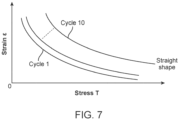
- FIG. 7 is a stress-strain graph, particularly showing an effect of thermal cycling.
- the transition temperature at which the embolic device 100 will change from the delivery shape to the deployed shape can be selectively configured using material composition and/or manufacturing process.
- the Austenite finishing temperature may be selected for the manufacturing process for a certain given material so that the finished product will have a desired transition temperature.
- the catheter 20 may be steerable.
- the catheter 20 may include one or more steering wires configured to steer the distal end 22 of the catheter 20 in one or more directions.
- the catheter 20 may not be steerable. Instead, a guidewire may first be used to access the target site. Then the catheter 20 may be disposed over the guidewire, and advanced distally using the guidewire. In such cases, the catheter 20 may include a separate channel for accommodating the guidewire.
- the shaft 30 (shown in FIG. 1 ) is then advanced to push the embolic device 100 distally until a first distal portion of the embolic device 100 is outside the catheter 20 ( FIG. 8A ).
- the embolic device 100 has a straight profile when in room temperature residing inside the catheter 20. The straight profile is due to the embolic device 100 being in room temperature, and it is not due to any mechanical straightening imposed by the catheter 20. Accordingly, the embolic device 100 can be easier advanced distally. This feature also allows a longer embolic device 100 to be delivered if needed.
- the first portion of the elongated member 102 responds to body temperature by changing from its relatively straight shape to form a first part of the three-dimensional structure 112 when the first portion of the elongated member 102 is unconfined outside the catheter 20.
- the reversible Martensite segments e.g., segments 300, 304, 410, 414, etc.
- Austenite segments have curvilinear profiles to provide the delivery shape for the portions of the elongated member 102 that has been deployed.
- the irreversible Martensite segments (e.g., segments 302, 412, etc.) along the elongated member 102 remains in the Martensite phase.
- These irreversible Martensite segments are softer compared to the reversible Martensite segments, and therefore they are easier to be bent in response to force. Accordingly, as the first part of the three-dimensional structure 112 is delivered into the aneurysm, the loops of the three-dimensional structure 112 are pressed towards the wall of the aneurysm, which imposes a force onto the irreversible Martensite segments. These segments bend in response to the force, thereby allowing the delivered first part of the three-dimensional structure 112 to better conform to the shape of the aneurysm 700.
- the first part of the three-dimensional structure 112 has a shape that corresponds with an inner wall of the aneurysm.
- the first part of the three-dimensional structure 112 represented schematically by the dashed line in FIG. 8A , provides a frame defining the cavity 118 for accommodating subsequent portions of the embolic device 100 to be delivered.
- the first part of the three-dimensional structure 112 also provides a scaffolding across a neck 704 of an aneurysm 700, which assists in containing subsequent portion(s) of the elongated member 102 of the embolic device 100 to be delivered into the cavity 118.
- the shaft 30 may be advanced further to push a subsequent portion of the embolic device 100 out of the catheter 20 ( FIG. 8B ).
- the subsequent portion forms a second part of the three-dimensional structure 112 when the subsequent portion is unconfined outside the catheter 20.
- the second part of the three-dimensional structure 112 has a shape that allows it to fill at least some of the space in the cavity 118 defined by the first part of the three-dimensional structure 112.
- the scaffolding across the neck 704 of the aneurysm provided by the first part of the three-dimensional structure 112 prevents the second part of the three-dimensional structure 112 from escaping or falling out of the cavity 118 of the first part of the three-dimensional structure 112 and out of the aneurysm.
- the reversible Martensite segments along the elongated member 102 change phase to become Austenite segments in response to body temperature.
- These Austenite segments have curvilinear profiles to provide the delivery shape for the portions of the elongated member 102 that has been deployed.
- the irreversible Martensite segments along the elongated member 102 remains in the Martensite phase. These irreversible Martensite segments are softer compared to the reversible Martensite segments, and therefore they are easier to be bent in response to force.
- the loops of the three-dimensional structure 112 are pressed towards the wall of the aneurysm (or towards the first part of the three-dimensional structure 112), which imposes a force onto the irreversible Martensite segments. These segments bend in response to the force, thereby allowing the delivered second part of the three-dimensional structure 112 to better conform to the shape of the cavity to be filled.
- the distal end of the shaft 30 abuts against the proximal end of the elongated member 102, and is not mechanically attached to the proximal end of the elongated member 102. In such cases, the elongated member 102 becomes decoupled from the remaining part of the medical device 10 as soon as the proximal end of the elongated member 102 is pushed out of the catheter 20.
- the distal end of the shaft 30 may be mechanically connected to the proximal end of the elongated member 102, such as via a mechanical connector that is operable to disengage the proximal end of the elongated member 102 from the shaft 30.
- the distal end of the shaft 30 may be mechanically connected to the proximal end of the elongated member 102 via a disintegratable link, such as a link that can be disintegrated in response to application of a current.
- a disintegratable link such as a link that can be disintegrated in response to application of a current.
- Mechanical connectors and disintegratable links are well known in the art, and therefore will not be described in further detail.
- the embolic device 100 is advantageous because the softer individual discrete irreversible Martensite segments provide some flexibility for the embolic device 100, thereby allowing the embolic device 100 to bend easily in response to force. While certain discrete parts (the irreversible Martensite segments) of the embolic device 100 can be more easily bent, a majority of other parts (i.e., the reversible Martensite segments) of the embolic device 100 remains relatively stiffer compared to the irreversible Martensite segments, thereby allowing the shape of most of the parts of the embolic device 100 to be maintained within the body cavity.
- the embolic device 100 is also advantageous because it has a delivery shape within the catheter 20 that is relatively straight compared to its deployed shape. This allows the embolic device 100 to be advanced distally relative to the catheter 20 easily without use of significant axial pushing force, and reduces the risk of the embolic device 100 buckling within the catheter 20.
- multiple embolic devices 100 may be provided with different respective lengths.
- a doctor may measure a size of the aneurysm to be treated. For example, the doctor may perform measurement using one or more images of the aneurysm to determine the size of the aneurysm.
- the size may be a cross-sectional dimension of the aneurysm, a cross-sectional area of the aneurysm, a volume of the aneurysm, etc.
- one of the embolic devices 100 may then be selected based on the size of the aneurysm. For example, a longer embolic device 100 may be selected to occlude a larger aneurysm.
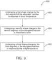
- FIG. 9 illustrates a method 800 of occluding a body lumen.
- the method 800 is performed by an embolic device having an elongated member, the elongated member comprising a first segment, a second segment, and a third segment, wherein the second segment is between the first segment and the third segment.
- the method 800 includes: undergoing a first shape change by the first segment of the elongated member in response to body temperature (item 802); undergoing a second shape change by the second segment of the elongated member in response to force (item 804); and undergoing a third shape change by the third segment of the elongated member in response to the body temperature (item 806).
- the embolic device in the method 800 may be the embolic device 100 described herein.
Landscapes
- Health & Medical Sciences (AREA)
- Surgery (AREA)
- Life Sciences & Earth Sciences (AREA)
- Heart & Thoracic Surgery (AREA)
- Molecular Biology (AREA)
- Vascular Medicine (AREA)
- Engineering & Computer Science (AREA)
- Biomedical Technology (AREA)
- Reproductive Health (AREA)
- Medical Informatics (AREA)
- Nuclear Medicine, Radiotherapy & Molecular Imaging (AREA)
- Animal Behavior & Ethology (AREA)
- General Health & Medical Sciences (AREA)
- Public Health (AREA)
- Veterinary Medicine (AREA)
- Neurosurgery (AREA)
- Surgical Instruments (AREA)
Claims (15)
- Embolievorrichtung (100) zur Anordnung in einem Körperlumen, wobei die Embolievorrichtung (100) Folgendes umfasst:ein längliches Element (102), das bei Raumtemperatur eine lineare Ausgestaltung aufweist, wobei das längliche Element (102) so ausgestaltet ist, dass es als Reaktion auf Körpertemperatur eine erste dreidimensionale Struktur (112) bildet,wobei sich Raumtemperatur auf eine Temperatur bezieht, die sich von der Körpertemperatur unterscheidet,wobei das längliche Element (102) ein erstes Segment (300), ein zweites Segment (302) und ein drittes Segment (304) umfasst, wobei sich das zweite Segment (302) zwischen dem ersten Segment (302) und dem dritten Segment (304) befindet,wobei das erste Segment (300) martensitisch ist, wenn das erste Segment (300) die Raumtemperatur aufweist, und austenitisch ist, wenn das erste Segment (300) die Körpertemperatur aufweist, undwobei das zweite Segment (302) martensitisch ist, wenn das zweite Segment (302) die Raumtemperatur aufweist, und auch martensitisch ist, wenn das zweite Segment (302) die Körpertemperatur aufweist;wobei das dritte Segment (304) martensitisch ist, wenn das dritte Segment (304) die Raumtemperatur aufweist, und austenitisch ist, wenn das dritte Segment (304) die Körpertemperatur aufweist.
- Embolievorrichtung nach Anspruch 1, wobei, als Reaktion auf die Körpertemperatur, das erste Segment (300) so ausgestaltet ist, dass es einen ersten Abschnitt einer Schleife bildet, und das dritte Segment (304) so ausgestaltet ist, dass es einen zweiten Abschnitt der Schleife bildet.
- Embolievorrichtung nach Anspruch 1, wobei, als Reaktion auf die Körpertemperatur, das erste Segment (300) so ausgestaltet ist, dass es eine erste Schleife bildet, und das dritte Segment (304) so ausgestaltet ist, dass es eine zweite Schleife bildet.
- Embolievorrichtung nach Anspruch 1,wobei das erste Segment (300) eine erste Länge aufweist, das zweite Segment (302) eine zweite Länge aufweist und das dritte Segment (304) eine dritte Länge aufweist, undwobei die zweite Länge des zweiten Segments (302) kürzer als die erste Länge des ersten Segments (300) ist und auch kürzer als die dritte Länge des dritten Segments (304) ist.
- Embolievorrichtung nach Anspruch 4, wobei die zweite Länge des zweiten Segments (302), das sich zwischen dem ersten Segment (300) und dem dritten Segment (304) befindet, kleiner als 50 % der ersten Länge des ersten Segments (300) ist und auch kleiner als 50 % der dritten Länge des dritten Segments (304) ist.
- Embolievorrichtung nach einem beliebigen der Ansprüche 1-5,wobei das längliche Element (102) ein distales Ende (104) und ein proximales Ende (106), das dem distalen Ende (104) entgegengesetzt ist, aufweist,wobei die Embolievorrichtung (100) ferner ein viertes Segment (410) umfasst, das das proximale Ende (106) umfasst, undwobei das vierte Segment (410) martensitisch ist, wenn es die Raumtemperatur aufweist, und auch martensitisch ist, wenn das vierte Segment (410) die Körpertemperatur aufweist.
- Embolievorrichtung nach einem beliebigen der Ansprüche 1-6, wobei die dreidimensionale Struktur (112) eine Vielzahl von Schleifen umfasst, und wobei das erste Segment (300), das zweite Segment (302) und das dritte Segment (304) jeweilige Abschnitte einer einzelnen der Schleifen umfassen.
- Embolievorrichtung nach Anspruch 7 in Abhängigkeit von Anspruch 1-5,wobei das längliche Element (102) ferner ein viertes Segment (410), ein fünftes Segment (412) und ein sechstes Segment (414) umfasst, die jeweilige Abschnitte einer anderen der Schleifen umfassen,wobei sich das fünfte Segment (412) zwischen dem vierten Segment (410) und dem sechsten Segment (414) befindet,wobei das vierte Segment (410) und das sechste Segment (414) martensitisch sind, wenn das vierte Segment (410) und das sechste Segment (414) die Raumtemperatur aufweisen, und austenitisch sind, wenn das vierte Segment (410) und das sechste Segment (414) die Körpertemperatur aufweisen, undwobei das fünfte Segment (412) martensitisch ist, wenn das fünfte Segment (412) die Raumtemperatur aufweist, und auch martensitisch ist, wenn das fünfte Segment (412) die Körpertemperatur aufweist.
- Embolievorrichtung nach Anspruch 1, wobei das zweite Segment (302) ein irreversibles martensitisches Segment umfasst.
- Embolievorrichtung nach Anspruch 1, wobei das zweite Segment (302), das sich zwischen dem ersten und dem dritten Segment (300, 304) befindet, weicher als das erste und das dritte Segment (300, 304) ist.
- Embolievorrichtung nach Anspruch 1, wobei das längliche Element ferner ein viertes Segment (400), ein fünftes Segment (402) und ein sechstes Segment (404) umfasst,wobei sich das fünfte Segment (402) zwischen dem vierten Segment (400) und dem sechsten Segment (404) befindet,wobei das vierte Segment (400) und das sechste Segment (404) so ausgestaltet sind, dass sie ihre jeweilige Form als Reaktion auf die Körpertemperatur ändern, undwobei das fünfte Segment (402), das sich zwischen dem vierten Segment (400) und dem sechsten Segment (404) befindet, eine Form aufweist, die unabhängig von der Körpertemperatur ist.
- Embolievorrichtung nach Anspruch 1, wobei das erste Segment (300) und das dritte Segment (304) so ausgestaltet sind, dass sie ihre jeweilige Form als Reaktion auf die Körpertemperatur ändern; und
wobei das zweite Segment (302), das sich zwischen dem ersten Segment (300) und dem dritten Segment (304) befindet, eine Form aufweist, die unabhängig von der Körpertemperatur ist. - Embolievorrichtung nach Anspruch 1, wobei sich das zweite Segment (302) zwischen zwei Schleifen befindet.
- Embolievorrichtung nach Anspruch 1, wobei sich das zweite Segment (302) an einem Wendepunkt zwischen zwei Schleifen befindet.
- Embolievorrichtung nach Anspruch 1, wobei das längliche Element (102) eine Flechtstruktur ist, und wobei ein Flechtwinkel entlang einer Länge des länglichen Elements (102) variiert.
Priority Applications (1)
| Application Number | Priority Date | Filing Date | Title |
|---|---|---|---|
| EP25168636.6A EP4555944A3 (de) | 2019-11-11 | 2020-11-06 | Embolievorrichtungen zum verschliessen von körperlumen |
Applications Claiming Priority (2)
| Application Number | Priority Date | Filing Date | Title |
|---|---|---|---|
| US16/679,646 US11819216B2 (en) | 2019-11-11 | 2019-11-11 | Embolic devices for occluding body lumens |
| PCT/US2020/059499 WO2021096782A1 (en) | 2019-11-11 | 2020-11-06 | Embolic devices for occluding body lumens |
Related Child Applications (1)
| Application Number | Title | Priority Date | Filing Date |
|---|---|---|---|
| EP25168636.6A Division EP4555944A3 (de) | 2019-11-11 | 2020-11-06 | Embolievorrichtungen zum verschliessen von körperlumen |
Publications (2)
| Publication Number | Publication Date |
|---|---|
| EP4057915A1 EP4057915A1 (de) | 2022-09-21 |
| EP4057915B1 true EP4057915B1 (de) | 2025-04-30 |
Family
ID=73654917
Family Applications (2)
| Application Number | Title | Priority Date | Filing Date |
|---|---|---|---|
| EP25168636.6A Pending EP4555944A3 (de) | 2019-11-11 | 2020-11-06 | Embolievorrichtungen zum verschliessen von körperlumen |
| EP20817145.4A Active EP4057915B1 (de) | 2019-11-11 | 2020-11-06 | Embolievorrichtung zum verschliessen von körperlumen |
Family Applications Before (1)
| Application Number | Title | Priority Date | Filing Date |
|---|---|---|---|
| EP25168636.6A Pending EP4555944A3 (de) | 2019-11-11 | 2020-11-06 | Embolievorrichtungen zum verschliessen von körperlumen |
Country Status (5)
| Country | Link |
|---|---|
| US (3) | US11819216B2 (de) |
| EP (2) | EP4555944A3 (de) |
| JP (2) | JP2022554402A (de) |
| ES (1) | ES3030486T3 (de) |
| WO (1) | WO2021096782A1 (de) |
Families Citing this family (4)
| Publication number | Priority date | Publication date | Assignee | Title |
|---|---|---|---|---|
| US11357511B2 (en) | 2008-05-01 | 2022-06-14 | Aneuclose Llc | Intrasacular aneurysm occlusion device with globular first configuration and bowl-shaped second configuration |
| US11583289B2 (en) | 2008-05-01 | 2023-02-21 | Aneuclose Llc | Aneurysm-occluding mesh ribbon with a series of loops or segments having distal-to-proximal variation in size, shape, and/or orientation |
| US11471164B2 (en) | 2008-05-01 | 2022-10-18 | Aneuclose Llc | Methods of occluding a cerebral aneurysm by inserting embolic members or material into an intrasacular implant |
| US11819216B2 (en) * | 2019-11-11 | 2023-11-21 | Stryker Corporation | Embolic devices for occluding body lumens |
Family Cites Families (13)
| Publication number | Priority date | Publication date | Assignee | Title |
|---|---|---|---|---|
| IL121316A (en) * | 1997-07-15 | 2001-07-24 | Litana Ltd | A medical device for planting in an alloy body with memory properties |
| US20050187564A1 (en) * | 1999-12-23 | 2005-08-25 | Swaminathan Jayaraman | Occlusive coil manufacturing and delivery |
| DE10155191A1 (de) * | 2001-11-12 | 2003-05-22 | Dendron Gmbh | Medizinisches Implantat |
| US20060206140A1 (en) * | 2005-02-24 | 2006-09-14 | Samuel Shaolian | Adjustable embolic aneurysm coil |
| US20080087508A1 (en) * | 2006-10-16 | 2008-04-17 | Kenmode Tool And Engineering, Inc. | Drum brake adjusters |
| EP2162101B1 (de) | 2007-06-25 | 2019-02-20 | MicroVention, Inc. | Selbstexpandierende prothese |
| US8764772B2 (en) | 2008-02-21 | 2014-07-01 | Cook Medical Technologies Llc | Occlusion device |
| US8702746B2 (en) * | 2008-04-29 | 2014-04-22 | Cook Medical Technologies Llc | Device and method for occlusion of fluid flow through a body vessel |
| US20100069948A1 (en) * | 2008-09-12 | 2010-03-18 | Micrus Endovascular Corporation | Self-expandable aneurysm filling device, system and method of placement |
| US9687245B2 (en) | 2012-03-23 | 2017-06-27 | Covidien Lp | Occlusive devices and methods of use |
| JP6241969B2 (ja) * | 2014-05-28 | 2017-12-06 | ストライカー ヨーロピアン ホールディングス I,エルエルシーStryker European Holdings I,Llc | 血管閉塞器具及びその使用方法 |
| JP6936312B2 (ja) * | 2017-03-30 | 2021-09-15 | テルモ株式会社 | 親水性部材と疎水性部材とを積層させた医療機器 |
| US11819216B2 (en) * | 2019-11-11 | 2023-11-21 | Stryker Corporation | Embolic devices for occluding body lumens |
-
2019
- 2019-11-11 US US16/679,646 patent/US11819216B2/en active Active
-
2020
- 2020-11-06 WO PCT/US2020/059499 patent/WO2021096782A1/en not_active Ceased
- 2020-11-06 EP EP25168636.6A patent/EP4555944A3/de active Pending
- 2020-11-06 EP EP20817145.4A patent/EP4057915B1/de active Active
- 2020-11-06 JP JP2022526758A patent/JP2022554402A/ja active Pending
- 2020-11-06 ES ES20817145T patent/ES3030486T3/es active Active
-
2023
- 2023-10-11 US US18/485,128 patent/US12133652B2/en active Active
-
2024
- 2024-09-18 US US18/888,812 patent/US20250009359A1/en active Pending
-
2025
- 2025-04-03 JP JP2025061537A patent/JP2025111481A/ja active Pending
Also Published As
| Publication number | Publication date |
|---|---|
| US12133652B2 (en) | 2024-11-05 |
| EP4555944A2 (de) | 2025-05-21 |
| WO2021096782A1 (en) | 2021-05-20 |
| ES3030486T3 (en) | 2025-06-30 |
| CN114650782A (zh) | 2022-06-21 |
| US20210137529A1 (en) | 2021-05-13 |
| JP2025111481A (ja) | 2025-07-30 |
| US11819216B2 (en) | 2023-11-21 |
| JP2022554402A (ja) | 2022-12-28 |
| US20250009359A1 (en) | 2025-01-09 |
| EP4555944A3 (de) | 2025-08-06 |
| EP4057915A1 (de) | 2022-09-21 |
| US20240032937A1 (en) | 2024-02-01 |
Similar Documents
| Publication | Publication Date | Title |
|---|---|---|
| US12133652B2 (en) | Embolic devices for occluding body lumens | |
| US11911040B2 (en) | Flow attenuation device | |
| JP7195375B2 (ja) | 塞栓器具およびその製造方法 | |
| US7338503B2 (en) | Non-invasive surgical ligation clip system and method of using | |
| US8366738B2 (en) | Tethered coil for treatment of body lumens | |
| US10893868B2 (en) | Aneurysm treatment coils | |
| JP4696064B2 (ja) | 改良された塞栓コイル | |
| US12178439B2 (en) | Embolic devices for occluding body lumens | |
| JP2019209152A (ja) | 血管内医療システムで使用するための非外傷性血塊回避構成遠位端を有するガイドワイヤ | |
| JP2002523125A (ja) | 血管閉塞コイル | |
| CN114650782B (en) | Embolic device for occluding body cavities | |
| KR20120138976A (ko) | 뇌동맥류 치료용 생체 금속 튜브형 보조 스텐트 및 전달 시스템 |
Legal Events
| Date | Code | Title | Description |
|---|---|---|---|
| STAA | Information on the status of an ep patent application or granted ep patent |
Free format text: STATUS: UNKNOWN |
|
| STAA | Information on the status of an ep patent application or granted ep patent |
Free format text: STATUS: THE INTERNATIONAL PUBLICATION HAS BEEN MADE |
|
| PUAI | Public reference made under article 153(3) epc to a published international application that has entered the european phase |
Free format text: ORIGINAL CODE: 0009012 |
|
| STAA | Information on the status of an ep patent application or granted ep patent |
Free format text: STATUS: REQUEST FOR EXAMINATION WAS MADE |
|
| 17P | Request for examination filed |
Effective date: 20220609 |
|
| AK | Designated contracting states |
Kind code of ref document: A1 Designated state(s): AL AT BE BG CH CY CZ DE DK EE ES FI FR GB GR HR HU IE IS IT LI LT LU LV MC MK MT NL NO PL PT RO RS SE SI SK SM TR |
|
| DAV | Request for validation of the european patent (deleted) | ||
| DAX | Request for extension of the european patent (deleted) | ||
| GRAP | Despatch of communication of intention to grant a patent |
Free format text: ORIGINAL CODE: EPIDOSNIGR1 |
|
| STAA | Information on the status of an ep patent application or granted ep patent |
Free format text: STATUS: GRANT OF PATENT IS INTENDED |
|
| GRAJ | Information related to disapproval of communication of intention to grant by the applicant or resumption of examination proceedings by the epo deleted |
Free format text: ORIGINAL CODE: EPIDOSDIGR1 |
|
| STAA | Information on the status of an ep patent application or granted ep patent |
Free format text: STATUS: REQUEST FOR EXAMINATION WAS MADE |
|
| GRAP | Despatch of communication of intention to grant a patent |
Free format text: ORIGINAL CODE: EPIDOSNIGR1 |
|
| STAA | Information on the status of an ep patent application or granted ep patent |
Free format text: STATUS: GRANT OF PATENT IS INTENDED |
|
| INTG | Intention to grant announced |
Effective date: 20241111 |
|
| RAP3 | Party data changed (applicant data changed or rights of an application transferred) |
Owner name: STRYKER EUROPEAN OPERATIONS LIMITED Owner name: STRYKER CORPORATION |
|
| INTC | Intention to grant announced (deleted) | ||
| INTG | Intention to grant announced |
Effective date: 20241204 |
|
| GRAS | Grant fee paid |
Free format text: ORIGINAL CODE: EPIDOSNIGR3 |
|
| GRAA | (expected) grant |
Free format text: ORIGINAL CODE: 0009210 |
|
| STAA | Information on the status of an ep patent application or granted ep patent |
Free format text: STATUS: THE PATENT HAS BEEN GRANTED |
|
| P01 | Opt-out of the competence of the unified patent court (upc) registered |
Free format text: CASE NUMBER: APP_10779/2025 Effective date: 20250305 |
|
| AK | Designated contracting states |
Kind code of ref document: B1 Designated state(s): AL AT BE BG CH CY CZ DE DK EE ES FI FR GB GR HR HU IE IS IT LI LT LU LV MC MK MT NL NO PL PT RO RS SE SI SK SM TR |
|
| REG | Reference to a national code |
Ref country code: CH Ref legal event code: EP Ref country code: GB Ref legal event code: FG4D |
|
| REG | Reference to a national code |
Ref country code: IE Ref legal event code: FG4D |
|
| REG | Reference to a national code |
Ref country code: DE Ref legal event code: R096 Ref document number: 602020050529 Country of ref document: DE |
|
| REG | Reference to a national code |
Ref country code: NL Ref legal event code: FP |
|
| REG | Reference to a national code |
Ref country code: ES Ref legal event code: FG2A Ref document number: 3030486 Country of ref document: ES Kind code of ref document: T3 Effective date: 20250630 |
|
| REG | Reference to a national code |
Ref country code: AT Ref legal event code: MK05 Ref document number: 1789292 Country of ref document: AT Kind code of ref document: T Effective date: 20250430 |
|
| PG25 | Lapsed in a contracting state [announced via postgrant information from national office to epo] |
Ref country code: FI Free format text: LAPSE BECAUSE OF FAILURE TO SUBMIT A TRANSLATION OF THE DESCRIPTION OR TO PAY THE FEE WITHIN THE PRESCRIBED TIME-LIMIT Effective date: 20250430 Ref country code: PT Free format text: LAPSE BECAUSE OF FAILURE TO SUBMIT A TRANSLATION OF THE DESCRIPTION OR TO PAY THE FEE WITHIN THE PRESCRIBED TIME-LIMIT Effective date: 20250901 |
|
| REG | Reference to a national code |
Ref country code: LT Ref legal event code: MG9D |
|
| PG25 | Lapsed in a contracting state [announced via postgrant information from national office to epo] |
Ref country code: NO Free format text: LAPSE BECAUSE OF FAILURE TO SUBMIT A TRANSLATION OF THE DESCRIPTION OR TO PAY THE FEE WITHIN THE PRESCRIBED TIME-LIMIT Effective date: 20250730 Ref country code: GR Free format text: LAPSE BECAUSE OF FAILURE TO SUBMIT A TRANSLATION OF THE DESCRIPTION OR TO PAY THE FEE WITHIN THE PRESCRIBED TIME-LIMIT Effective date: 20250731 |
|
| PG25 | Lapsed in a contracting state [announced via postgrant information from national office to epo] |
Ref country code: PL Free format text: LAPSE BECAUSE OF FAILURE TO SUBMIT A TRANSLATION OF THE DESCRIPTION OR TO PAY THE FEE WITHIN THE PRESCRIBED TIME-LIMIT Effective date: 20250430 |
|
| PGFP | Annual fee paid to national office [announced via postgrant information from national office to epo] |
Ref country code: NL Payment date: 20250912 Year of fee payment: 6 |
|
| PG25 | Lapsed in a contracting state [announced via postgrant information from national office to epo] |
Ref country code: BG Free format text: LAPSE BECAUSE OF FAILURE TO SUBMIT A TRANSLATION OF THE DESCRIPTION OR TO PAY THE FEE WITHIN THE PRESCRIBED TIME-LIMIT Effective date: 20250430 |
|
| PGFP | Annual fee paid to national office [announced via postgrant information from national office to epo] |
Ref country code: GB Payment date: 20250918 Year of fee payment: 6 |
|
| PG25 | Lapsed in a contracting state [announced via postgrant information from national office to epo] |
Ref country code: HR Free format text: LAPSE BECAUSE OF FAILURE TO SUBMIT A TRANSLATION OF THE DESCRIPTION OR TO PAY THE FEE WITHIN THE PRESCRIBED TIME-LIMIT Effective date: 20250430 |
|
| PG25 | Lapsed in a contracting state [announced via postgrant information from national office to epo] |
Ref country code: AT Free format text: LAPSE BECAUSE OF FAILURE TO SUBMIT A TRANSLATION OF THE DESCRIPTION OR TO PAY THE FEE WITHIN THE PRESCRIBED TIME-LIMIT Effective date: 20250430 |
|
| PGFP | Annual fee paid to national office [announced via postgrant information from national office to epo] |
Ref country code: FR Payment date: 20250908 Year of fee payment: 6 |
|
| PG25 | Lapsed in a contracting state [announced via postgrant information from national office to epo] |
Ref country code: RS Free format text: LAPSE BECAUSE OF FAILURE TO SUBMIT A TRANSLATION OF THE DESCRIPTION OR TO PAY THE FEE WITHIN THE PRESCRIBED TIME-LIMIT Effective date: 20250731 |
|
| PGFP | Annual fee paid to national office [announced via postgrant information from national office to epo] |
Ref country code: IE Payment date: 20250909 Year of fee payment: 6 |
|
| PG25 | Lapsed in a contracting state [announced via postgrant information from national office to epo] |
Ref country code: IS Free format text: LAPSE BECAUSE OF FAILURE TO SUBMIT A TRANSLATION OF THE DESCRIPTION OR TO PAY THE FEE WITHIN THE PRESCRIBED TIME-LIMIT Effective date: 20250830 |
|
| PG25 | Lapsed in a contracting state [announced via postgrant information from national office to epo] |
Ref country code: LV Free format text: LAPSE BECAUSE OF FAILURE TO SUBMIT A TRANSLATION OF THE DESCRIPTION OR TO PAY THE FEE WITHIN THE PRESCRIBED TIME-LIMIT Effective date: 20250430 |
|
| PGFP | Annual fee paid to national office [announced via postgrant information from national office to epo] |
Ref country code: DE Payment date: 20250910 Year of fee payment: 6 |
|
| PG25 | Lapsed in a contracting state [announced via postgrant information from national office to epo] |
Ref country code: DK Free format text: LAPSE BECAUSE OF FAILURE TO SUBMIT A TRANSLATION OF THE DESCRIPTION OR TO PAY THE FEE WITHIN THE PRESCRIBED TIME-LIMIT Effective date: 20250430 Ref country code: SM Free format text: LAPSE BECAUSE OF FAILURE TO SUBMIT A TRANSLATION OF THE DESCRIPTION OR TO PAY THE FEE WITHIN THE PRESCRIBED TIME-LIMIT Effective date: 20250430 |
|
| PGFP | Annual fee paid to national office [announced via postgrant information from national office to epo] |
Ref country code: IT Payment date: 20251022 Year of fee payment: 6 |
|
| PG25 | Lapsed in a contracting state [announced via postgrant information from national office to epo] |
Ref country code: CZ Free format text: LAPSE BECAUSE OF FAILURE TO SUBMIT A TRANSLATION OF THE DESCRIPTION OR TO PAY THE FEE WITHIN THE PRESCRIBED TIME-LIMIT Effective date: 20250430 |
|
| PG25 | Lapsed in a contracting state [announced via postgrant information from national office to epo] |
Ref country code: EE Free format text: LAPSE BECAUSE OF FAILURE TO SUBMIT A TRANSLATION OF THE DESCRIPTION OR TO PAY THE FEE WITHIN THE PRESCRIBED TIME-LIMIT Effective date: 20250430 |
|
| PG25 | Lapsed in a contracting state [announced via postgrant information from national office to epo] |
Ref country code: SK Free format text: LAPSE BECAUSE OF FAILURE TO SUBMIT A TRANSLATION OF THE DESCRIPTION OR TO PAY THE FEE WITHIN THE PRESCRIBED TIME-LIMIT Effective date: 20250430 |
|
| PGFP | Annual fee paid to national office [announced via postgrant information from national office to epo] |
Ref country code: ES Payment date: 20251212 Year of fee payment: 6 |
|
| REG | Reference to a national code |
Ref country code: DE Ref legal event code: R097 Ref document number: 602020050529 Country of ref document: DE |
|
| PG25 | Lapsed in a contracting state [announced via postgrant information from national office to epo] |
Ref country code: RO Free format text: LAPSE BECAUSE OF FAILURE TO SUBMIT A TRANSLATION OF THE DESCRIPTION OR TO PAY THE FEE WITHIN THE PRESCRIBED TIME-LIMIT Effective date: 20250430 |
|
| PLBE | No opposition filed within time limit |
Free format text: ORIGINAL CODE: 0009261 |
|
| STAA | Information on the status of an ep patent application or granted ep patent |
Free format text: STATUS: NO OPPOSITION FILED WITHIN TIME LIMIT |
|
| REG | Reference to a national code |
Ref country code: CH Ref legal event code: L10 Free format text: ST27 STATUS EVENT CODE: U-0-0-L10-L00 (AS PROVIDED BY THE NATIONAL OFFICE) Effective date: 20260311 |
|
| 26N | No opposition filed |
Effective date: 20260202 |