EP4056522B1 - Anlage zum verschliessen von behältern mit einem transfersternrad und verfahren zum fördern von behältern - Google Patents
Anlage zum verschliessen von behältern mit einem transfersternrad und verfahren zum fördern von behältern Download PDFInfo
- Publication number
- EP4056522B1 EP4056522B1 EP22159031.8A EP22159031A EP4056522B1 EP 4056522 B1 EP4056522 B1 EP 4056522B1 EP 22159031 A EP22159031 A EP 22159031A EP 4056522 B1 EP4056522 B1 EP 4056522B1
- Authority
- EP
- European Patent Office
- Prior art keywords
- containers
- capping
- container
- gripping member
- wheel
- Prior art date
- Legal status (The legal status is an assumption and is not a legal conclusion. Google has not performed a legal analysis and makes no representation as to the accuracy of the status listed.)
- Active
Links
Images


Classifications
-
- B—PERFORMING OPERATIONS; TRANSPORTING
- B67—OPENING, CLOSING OR CLEANING BOTTLES, JARS OR SIMILAR CONTAINERS; LIQUID HANDLING
- B67B—APPLYING CLOSURE MEMBERS TO BOTTLES JARS, OR SIMILAR CONTAINERS; OPENING CLOSED CONTAINERS
- B67B3/00—Closing bottles, jars or similar containers by applying caps
- B67B3/20—Closing bottles, jars or similar containers by applying caps by applying and rotating preformed threaded caps
- B67B3/2013—Closing bottles, jars or similar containers by applying caps by applying and rotating preformed threaded caps by carousel-type capping machines
-
- B—PERFORMING OPERATIONS; TRANSPORTING
- B67—OPENING, CLOSING OR CLEANING BOTTLES, JARS OR SIMILAR CONTAINERS; LIQUID HANDLING
- B67C—CLEANING, FILLING WITH LIQUIDS OR SEMILIQUIDS, OR EMPTYING, OF BOTTLES, JARS, CANS, CASKS, BARRELS, OR SIMILAR CONTAINERS, NOT OTHERWISE PROVIDED FOR; FUNNELS
- B67C7/00—Concurrent cleaning, filling, and closing of bottles; Processes or devices for at least two of these operations
- B67C7/0006—Conveying; Synchronising
- B67C7/004—Conveying; Synchronising the containers travelling along a circular path
- B67C7/0046—Infeed and outfeed devices
- B67C7/0053—Infeed and outfeed devices using grippers
Definitions
- the present invention relates to a capping plant for capping containers using a transfer star-wheel and a method for conveying containers.
- the reference sector for the present invention is the bottling of so-called "sensitive" food products, i.e. products that are particularly sensitive to bacteriological contamination and oxidation, such as, for example, isotonic drinks, juices, nectars, soft drinks, tea, milk-based beverages, coffee-based beverages, etc., for which avoiding possible microbiological contamination throughout all packaging steps is of fundamental importance.
- sensitive food products i.e. products that are particularly sensitive to bacteriological contamination and oxidation, such as, for example, isotonic drinks, juices, nectars, soft drinks, tea, milk-based beverages, coffee-based beverages, etc., for which avoiding possible microbiological contamination throughout all packaging steps is of fundamental importance.
- the present invention relates in particular to bottling lines with aseptic technology where maintaining sterility is of fundamental importance.
- the present invention can also be used in non-aseptic filling and capping systems.
- containers made of thermoplastic material leaving a capping unit are moved on a transfer star-wheel by means of a support for the neck, regardless of the format. At the end of their path on the transfer star-wheel, the containers are delivered to a conveyor belt, which supports the bottoms thereof.
- a capping plant is known from WO 2020/070026 A1 .
- movement by supporting the neck ensures that the neck is always at the same height, whereas the bottom is always at a different height according to the format of the container.
- a first solution of the known type adopted to overcome this drawback envisages the use of a tilting belt at the output of the transfer star-wheel.
- the conveyor belt comprises a portion that is movable in height to adapt to the format of the containers.
- a second solution of the known type envisages equipping the transfer star-wheel with a helical slide that places it in communication with the conveyor belt.
- Document DE 10 2017 120558 A1 describes a treatment apparatus that can be a closure apparatus in the form of a carousel. Containers are raised or lowered within the carousel by lifting devices.
- Document CN 110499380 A discloses a transfer star wheel in which containers are raised using movement means comprising grippers and a cam.
- the technical task underpinning the present invention is that of proposing a a capping plant for capping containers using a transfer star-wheel and a method for conveying containers, which obviate the drawbacks of the prior art cited above.
- the object of the present invention is to propose a capping plant for capping containers and a conveying method, which enable the transport of any container format, i.e. which enable format changes to be performed more quickly and, for aseptic machines, without any loss of sterility.
- Such plant comprises among other a star-wheel for containers of thermoplastic material, comprising:
- the movement means is movable along a direction that is substantially parallel to the sliding direction so as to be able to vary the lower and/or upper limit position.
- the movement means comprises a cam so shaped as to define for each revolution of the rotating carousel a movement of the gripping member along the sliding direction between the lower limit position and the upper limit position.
- the movement means comprises a roller connected to the gripping member and placed in contact with the cam.
- the movement means comprises a jack that is operationally active on the roller to keep it in contact with the cam.
- the movement means comprises for each gripping member a linear electric motor or a stepper motor associated with a recirculation guide.
- the containers are provided with a concave closure, for example a cap or capsule.
- Each support station comprises an abutment element located above the corresponding gripping member.
- the abutment element can be configured in an operating position in which it is in contact with the concave closure of the container supported by the corresponding gripping member, and a neutral position in which it is distanced from the concave closure.
- the capping plant further comprises:
- the star-wheel is located downstream of the capping unit to receive the capped containers, i.e. containers to which the concave closures have been applied.
- An output belt is located downstream of the transfer star-wheel.
- the method for conveying containers made of thermoplastic material comprises among other steps of:
- the method comprises a step of unloading each container at the point of delivery onto a support surface located at said set height.
- the conveying path is defined by an outer circumference of the rotating carousel.
- the step of sustaining each container takes place by gripping members that sustain each container by its neck.
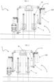
- the number 1 indicates a transfer star-wheel for containers made of thermoplastic material.
- the transfer star-wheel 1 comprises a rotary carousel 2 having a plurality of support stations 3 for supporting the containers 100.
- Each support station 3 comprises a gripping member 4 for gripping (that is grasping) one of the containers 100 by its neck 100b.
- the gripping member 4 is arranged at the outer circumference of the rotating carousel 2.
- the gripping members 4 are equally spaced along the outer circumference of the rotating carousel 2.
- the gripping member 4 is a gripper solidly fixed to the rotating carousel 2.
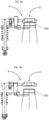
- the transfer star-wheel 1 comprises a movement means 5 operationally active on each gripping member 4 to move it along a sliding direction substantially orthogonal to the rotating carousel 2.
- the sliding direction is a direction for which the height of the gripping member 4 varies with respect to a base of the transfer star-wheel 1. Moving the gripping member 4 along the sliding direction also causes the height of the neck 100a and of the bottom 100b of the supported container 100 to change.
- the movement means 5 comprises a cam 8 having a profile such as to move each gripping member 4 along the sliding direction.
- the cam 8 is shaped such as to define for each revolution of the rotating carousel 2 an upward/downward path of the gripping member 4 along the sliding direction between a lower limit position and/or an upper limit position.
- the movement means 5 comprises a roller kept in contact with the cam 8 which transfers motion to the gripping member 4.
- the movement means 5 comprises a jack 7 that is operationally active on the roller to keep it in contact with the cam 8.
- the jack 7 may be, for example, air operated (working like an air spring), or mechanical, i.e. provided with helical springs.
- the cam 8 can be moved along a direction substantially parallel to the sliding direction.
- the cam 8 is adjustable in height. In this way, it is possible to vary the lower limit position and possibly the upper limit position of the gripping member 4 according to the format of the container 100.
- the upper limit position of the gripping member 4 is assumed to receive a container from the station or transfer star-wheel located upstream.
- the upper limit position is the same for all container formats.
- the lower limit position is instead varied according to the format.
- the movement of the cam 8 can take place according to systems of the known type. For example, it is possible to use a mechanical system or a stepper motor or a linear electric motor.
- the cam 8 is fixed to a support 9 fixed to sliding bushings onto one or more threaded bars 10 for lifting the cam 8.
- the cam 8 is therefore adjustable in height by varying the position of the bushing along the threaded bar 10.
- the movement means 5 comprises a linear electric motor for each gripping member 4.
- the movement means 5 comprises, for each gripping member 4, a stepper motor associated with a recirculating ball guide.
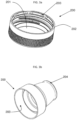
- the containers 100 are made of thermoplastic material, e.g. PET, provided with a concave closure 200.
- thermoplastic material e.g. PET
- Every container 100 has a tubular body 100a and a threaded neck 100b, as shown in figure 6 .
- concave closure means a cap or a capsule.
- the concave closure is preferably made of polymeric material.
- the flat cap concave closure 200 has a discoid base 201, and a substantially cylindrical lateral surface 202 which extends from the discoid base 201 and defines a cavity 203 therewith. On the opposite side to the discoid base 201, the cavity 203 is open so as to accommodate the mouth of the container 100. This closure is illustrated in figure 3a .
- the sport cap concave closure 200 has a projecting spout 204 instead of the discoid base. This figure is illustrated in figure 3b .
- each support station 3 comprises an abutment element 11 located above the corresponding gripping member 4.
- the abutment element 11 can have two configurations:
- each abutment element 11 is shaped like a concave shell (or bell) configured to be applied to the concave closure 200 so as to partially surround it.
- the abutment element 11 partially surrounds the concave closure 200 when it is in the operating position. In this case, thanks to the partial surrounding of the closure, it is sufficient for the abutment element 11 to rest (without pressing) on the underlying closure.
- the concave shell 11 is configured to be applied to the spout 204 of the sport cap 200 so as to surround it.
- the concave shell 11 can also be applied to a flat cap 200. In that case, the concave shell 11 surrounds the upper part of the discoid base 201 and the first section of the lateral surface 202 of the flat cap 200.
- the abutment element 11 is made of metal, for example steel, or plastic.
- each abutment element 11 is a full body having a substantially flat surface which contacts the concave closure 200 and presses thereon.
- a guide means 12 configured to contact the neck 100b of each container 100 on the opposite side with respect to the rotating carousel 2.
- the guide means 12 is arranged so as to contact, at the bottom, the part of bead 100c exposed towards the outside of the gripping member 4, i.e. the part of bead 100c which does not rest on the rotating carousel 2 or on the gripper 4.
- such guide means 12 consists of a profile which extends at least partially outside the rotating carousel 2 following the circumferential extension, as can be seen in figure 5 .
- the profile 12 consists of a slab having a partially annular shape which is arranged below the part of bead 100c of the containers 100 facing towards the outside of the gripping member 4.
- the guide means 12 is present when heavy containers 100 are moved, with a capacity of 1.75-2 litres, or when the transfer star-wheel 1 transports more than 40000 bottles/hour, or for sport cap applications ( fig. 3b ) in which the abutment element 11 contacts the cap without pressing on it.
- Number 20 indicates a capping plant for containers made of thermoplastic material.
- the capping plant 20 comprises a capping unit 21 comprising a plurality of capping stations 111 for applying closures 200 to the containers 100.
- a transfer star-wheel 1 is located downstream of the capping unit 21 to receive the capped containers 100, i.e. containers to which the closures 200 have been applied.
- the capping plant 20 comprises an output belt 22 located downstream of the star-wheel 1.
- the gripping member 4 is moved along the sliding direction so that the bottom of the container 100 is at the output belt 22.
- the cam profile 8 is made so that the uphill/downhill path imparted to the gripping member 4 enables the bottom of the container 100 to be brought to the output belt 22.
- a method for conveying containers 100 is described below.
- the method is advantageously implemented by a transfer star-wheel 1 as described above.
- the method comprises the step of supporting each container 100 along a conveying path from a pickup point A to a delivery point B.
- each container 100 is moved in height by a set amount.
- the set amount is selected so as to have each container 100 at the delivery point B having the bottom at a set height.
- the method comprises a step of unloading each container 100 at the point of delivery B onto a support surface located at the set height.
- the conveying path is defined by an outer circumference of a rotating carousel 2.
- the step of supporting each container 100 occurs through the action of grippers 4 that support each container 100 by the neck 100b thereof.
- the combination of the movement of the gripping member between the two limit positions by the jack and the height adjustment of the cam enable any type of container format to be conveyed. In fact, it is possible to quickly perform a format change on the plant by adjusting the height of the cam, causing two new lower and upper limit positions of the stroke of the gripping member.
Landscapes
- Engineering & Computer Science (AREA)
- Mechanical Engineering (AREA)
- Specific Conveyance Elements (AREA)
- Sealing Of Jars (AREA)
Claims (8)
- Verschließanlage (20) zum Verschließen von Behältern (100) aus thermoplastischem Material, umfassend:eine Verschließeinheit (21), umfassend eine Vielzahl von Verschließstationen (111) zum Anbringen von Verschlüssen (200) an den Behältern (100);ein Transfersternrad (1), das stromabwärts der Verschließeinheit (21) befindlich ist, um die verschlossenen Behälter (200), d. h., an denen die Verschlüsse (200) angebracht wurden, aufzunehmen;ein Austransportband (22), das stromabwärts des Transfersternrads (1) befindlich ist,wobei das Transfersternrad (1) Folgendes umfasst:ein Drehkarussell (2), aufweisend eine Vielzahl von Tragestationen (3) für die Behälter (100), wobei eine jede Tragestation (3) ein Greifelement (4) zum Greifen von einem der Behälter (100) mittels dessen Halses (100b) an einem äußeren Umfang des Drehkarussells (2) umfasst;Bewegungsmittel (5), die betriebswirksam auf ein jedes Greifelement (4) einwirken, um das Greifelement (4) entlang einer Verschieberichtung, die im Wesentlichen rechtwinkelig zum Drehkarussell (2) verläuft, zwischen einer unteren Grenzposition und einer oberen Grenzposition zu bewegen, sodass die Unterseite des Behälters (100) an das Austransportband (22) gebracht wird, wobei die Bewegungsmittel (5) einen Nocken (8) umfassen, der so ausgeformt ist, dass für eine jede Umdrehung des Drehkarussells (2) eine Bewegung des Greifelements (4) entlang der Verschieberichtung zwischen der unteren Grenzposition und der oberen Grenzposition definiert wird,wobei die Bewegungsmittel (5) entlang einer Richtung bewegbar sind, die im Wesentlichen parallel zur Verschieberichtung verläuft, sodass die untere und/oder die obere Grenzposition variiert werden kann.
- Verschließanlage (20) nach Anspruch 1, wobei die Bewegungsmittel (5) eine Walze umfassen, die mit dem Greifelement (4) verbunden und in Kontakt mit dem Nocken (8) platziert ist, wobei die Bewegungsmittel (5) einen Hebebock (7) umfassen, der betriebswirksam auf die Walze einwirkt, um die Walze in Kontakt mit dem Nocken (8) zu halten.
- Verschließanlage (20) nach Anspruch 1, wobei die Bewegungsmittel (5) für ein jedes Greifelement (4) einen linearen Elektromotor oder einen Schrittmotor, assoziiert mit einer Umlaufführung, umfassen.
- Verschließanlage (20) nach einem der vorhergehenden Ansprüche, wobei die Behälter (100) mit einem konkaven Verschluss (200) versehen sind, eine jede Tragestation (3) ein Anschlagselement (11) umfasst, das oberhalb des entsprechenden Greifelements (4) befindlich ist, wobei das Anschlagselement (11) in einer Betriebsposition, in der es mit dem konkaven Verschluss (200) des vom entsprechenden Greifelement (4) getragenen Behälters (100) in Kontakt ist, und einer neutralen Position, in der es vom konkaven Verschluss (200) beabstandet angeordnet ist, auslegbar ist.
- Verfahren zum Fördern von Behältern (100) mittels eines Transfersternrads (1) einer Verschließanlage (20) nach einem der Ansprüche 1 bis 4, umfassend die folgenden Schritte:Tragen eines jeden Behälters (100) entlang eines Förderwegs von einem Aufnahmepunkt (A) zu einem Übergabepunkt (B) des Transfersternrads (1);während des Schritts zum Tragen eines jeden Behälters (100) Bewegen eines jeden Behälters (100) in der Höhe um eine vorgegebene Menge, wobei die vorgegebene Menge so ausgewählt wird, dass ein jeder Behälter (100) am Übergabepunkt (B) mit einer Unterseite auf einer vorgegebenen Höhe angeordnet ist.
- Verfahren nach Anspruch 5, zudem umfassend einen Schritt zum Abladen eines jeden Behälters (100) am Übergabepunkt (B) auf eine Trageoberfläche, die sich auf der vorgegebenen Höhe befindet.
- Verfahren nach Anspruch 5 oder 6, wobei der Förderweg durch einen äußeren Umfang eines Drehkarussells (2) definiert ist.
- Verfahren nach einem der Ansprüche 5 bis 7, wobei der Schritt zum Tragen eines jeden Behälters (100) durch die Wirkung von Greifelementen (4) stattfindet, die einen jeden Behälter (100) mittels dessen Halses (100b) tragen.
Applications Claiming Priority (1)
| Application Number | Priority Date | Filing Date | Title |
|---|---|---|---|
| IT102021000005540A IT202100005540A1 (it) | 2021-03-09 | 2021-03-09 | Stella di trasporto di recipienti, impianto di tappatura di recipienti impiegante tale stella di trasporto e metodo per trasportare recipienti |
Publications (3)
| Publication Number | Publication Date |
|---|---|
| EP4056522A1 EP4056522A1 (de) | 2022-09-14 |
| EP4056522C0 EP4056522C0 (de) | 2024-06-12 |
| EP4056522B1 true EP4056522B1 (de) | 2024-06-12 |
Family
ID=75937092
Family Applications (1)
| Application Number | Title | Priority Date | Filing Date |
|---|---|---|---|
| EP22159031.8A Active EP4056522B1 (de) | 2021-03-09 | 2022-02-25 | Anlage zum verschliessen von behältern mit einem transfersternrad und verfahren zum fördern von behältern |
Country Status (3)
| Country | Link |
|---|---|
| EP (1) | EP4056522B1 (de) |
| HU (1) | HUE067598T2 (de) |
| IT (1) | IT202100005540A1 (de) |
Family Cites Families (3)
| Publication number | Priority date | Publication date | Assignee | Title |
|---|---|---|---|---|
| DE102017120558A1 (de) * | 2017-09-06 | 2019-03-07 | Krones Ag | Vorrichtung und Verfahren zum Behandeln von Behältern in einer Behälterbehandlungsanlage |
| IT201800009188A1 (it) * | 2018-10-05 | 2020-04-05 | Gea Procomac Spa | Stella di trasporto e metodo di trasporto di recipienti in materiale termoplastico provvisti di chiusura concava e impianto di tappatura |
| CN110240105B (zh) * | 2019-07-03 | 2024-08-06 | 张家港市新斯达机械有限公司 | 一种气体饮料等压灌装三合一机 |
-
2021
- 2021-03-09 IT IT102021000005540A patent/IT202100005540A1/it unknown
-
2022
- 2022-02-25 EP EP22159031.8A patent/EP4056522B1/de active Active
- 2022-02-25 HU HUE22159031A patent/HUE067598T2/hu unknown
Also Published As
| Publication number | Publication date |
|---|---|
| HUE067598T2 (hu) | 2024-10-28 |
| IT202100005540A1 (it) | 2022-09-09 |
| EP4056522C0 (de) | 2024-06-12 |
| EP4056522A1 (de) | 2022-09-14 |
Similar Documents
| Publication | Publication Date | Title |
|---|---|---|
| EP3907162B1 (de) | Anlage zur verarbeitung von behältern | |
| EP1864942B1 (de) | Behältertransportband für Abfüllanlagen | |
| US11136231B2 (en) | Device for treating containers, and beverage filling system | |
| US6983577B2 (en) | Circular motion filling machine for processing parallel rows of containers and method | |
| US6341630B2 (en) | Filling and handling bottles | |
| EP2615046B1 (de) | Anlage und Verfahren zur Behandlung von Flaschen | |
| US8668074B2 (en) | Method for transferring an article | |
| CN102092502A (zh) | 用于传送容器的装置、方法及用于处理容器的设备 | |
| EP4072947A1 (de) | Maschine zum bewegen und handhaben von behältern, die ein rieselfähiges produkt enthalten | |
| CA3125255A1 (fr) | Line for preparing and filling bottles | |
| CN101253097A (zh) | 用于在一容器处理机中高度补偿的设备和方法 | |
| EP4056522B1 (de) | Anlage zum verschliessen von behältern mit einem transfersternrad und verfahren zum fördern von behältern | |
| EP3177536B1 (de) | Etikettiermaschine | |
| WO2011007370A1 (en) | Method and unit for conveying bottles | |
| JP2006193180A (ja) | 容器兼用可能な充填ラインの容器搬送システム | |
| EP2792634A1 (de) | Positionssteuerungssystem für eine Artikelhandhabungsmaschine und zugehöriges Verfahren | |
| EP3841024B1 (de) | Transferstern und verfahren | |
| EP3971130A1 (de) | Maschine zum füllen von behältern mit flüssigkeit und entsprechendes füllverfahren | |
| WO1999051514A1 (en) | Adjustable gripper for containers, in particular for a star conveyor | |
| EP2207745B1 (de) | Vorrichtung und verfahren zur behälterbefüllung | |
| WO2023078629A1 (en) | Gripper for gripping and holding containers adapted to be filled with a pourable product | |
| US11970380B2 (en) | Container-handling apparatus | |
| WO2011135598A1 (en) | Clamping device for clamping a plurality of capped containers and method for transferring a plurality of capped containers | |
| US11905154B2 (en) | Capping plant and a method for capping and conveying containers made of thermoplastic material | |
| US10273135B2 (en) | Machine for filling containers |
Legal Events
| Date | Code | Title | Description |
|---|---|---|---|
| PUAI | Public reference made under article 153(3) epc to a published international application that has entered the european phase |
Free format text: ORIGINAL CODE: 0009012 |
|
| STAA | Information on the status of an ep patent application or granted ep patent |
Free format text: STATUS: REQUEST FOR EXAMINATION WAS MADE |
|
| 17P | Request for examination filed |
Effective date: 20220727 |
|
| AK | Designated contracting states |
Kind code of ref document: A1 Designated state(s): AL AT BE BG CH CY CZ DE DK EE ES FI FR GB GR HR HU IE IS IT LI LT LU LV MC MK MT NL NO PL PT RO RS SE SI SK SM TR |
|
| P01 | Opt-out of the competence of the unified patent court (upc) registered |
Effective date: 20230526 |
|
| GRAP | Despatch of communication of intention to grant a patent |
Free format text: ORIGINAL CODE: EPIDOSNIGR1 |
|
| STAA | Information on the status of an ep patent application or granted ep patent |
Free format text: STATUS: GRANT OF PATENT IS INTENDED |
|
| GRAS | Grant fee paid |
Free format text: ORIGINAL CODE: EPIDOSNIGR3 |
|
| GRAA | (expected) grant |
Free format text: ORIGINAL CODE: 0009210 |
|
| STAA | Information on the status of an ep patent application or granted ep patent |
Free format text: STATUS: THE PATENT HAS BEEN GRANTED |
|
| INTG | Intention to grant announced |
Effective date: 20240416 |
|
| AK | Designated contracting states |
Kind code of ref document: B1 Designated state(s): AL AT BE BG CH CY CZ DE DK EE ES FI FR GB GR HR HU IE IS IT LI LT LU LV MC MK MT NL NO PL PT RO RS SE SI SK SM TR |
|
| REG | Reference to a national code |
Ref country code: GB Ref legal event code: FG4D |
|
| REG | Reference to a national code |
Ref country code: CH Ref legal event code: EP |
|
| REG | Reference to a national code |
Ref country code: DE Ref legal event code: R096 Ref document number: 602022003842 Country of ref document: DE |
|
| REG | Reference to a national code |
Ref country code: IE Ref legal event code: FG4D |
|
| U01 | Request for unitary effect filed |
Effective date: 20240624 |
|
| P04 | Withdrawal of opt-out of the competence of the unified patent court (upc) registered |
Free format text: CASE NUMBER: APP_38945/2024 Effective date: 20240629 |
|
| U07 | Unitary effect registered |
Designated state(s): AT BE BG DE DK EE FI FR IT LT LU LV MT NL PT SE SI Effective date: 20240703 |
|
| PG25 | Lapsed in a contracting state [announced via postgrant information from national office to epo] |
Ref country code: HR Free format text: LAPSE BECAUSE OF FAILURE TO SUBMIT A TRANSLATION OF THE DESCRIPTION OR TO PAY THE FEE WITHIN THE PRESCRIBED TIME-LIMIT Effective date: 20240612 |
|
| PG25 | Lapsed in a contracting state [announced via postgrant information from national office to epo] |
Ref country code: GR Free format text: LAPSE BECAUSE OF FAILURE TO SUBMIT A TRANSLATION OF THE DESCRIPTION OR TO PAY THE FEE WITHIN THE PRESCRIBED TIME-LIMIT Effective date: 20240913 |
|
| PG25 | Lapsed in a contracting state [announced via postgrant information from national office to epo] |
Ref country code: ES Free format text: LAPSE BECAUSE OF FAILURE TO SUBMIT A TRANSLATION OF THE DESCRIPTION OR TO PAY THE FEE WITHIN THE PRESCRIBED TIME-LIMIT Effective date: 20240612 |
|
| REG | Reference to a national code |
Ref country code: HU Ref legal event code: AG4A Ref document number: E067598 Country of ref document: HU |
|
| PG25 | Lapsed in a contracting state [announced via postgrant information from national office to epo] |
Ref country code: NO Free format text: LAPSE BECAUSE OF FAILURE TO SUBMIT A TRANSLATION OF THE DESCRIPTION OR TO PAY THE FEE WITHIN THE PRESCRIBED TIME-LIMIT Effective date: 20240912 Ref country code: HR Free format text: LAPSE BECAUSE OF FAILURE TO SUBMIT A TRANSLATION OF THE DESCRIPTION OR TO PAY THE FEE WITHIN THE PRESCRIBED TIME-LIMIT Effective date: 20240612 Ref country code: GR Free format text: LAPSE BECAUSE OF FAILURE TO SUBMIT A TRANSLATION OF THE DESCRIPTION OR TO PAY THE FEE WITHIN THE PRESCRIBED TIME-LIMIT Effective date: 20240913 Ref country code: ES Free format text: LAPSE BECAUSE OF FAILURE TO SUBMIT A TRANSLATION OF THE DESCRIPTION OR TO PAY THE FEE WITHIN THE PRESCRIBED TIME-LIMIT Effective date: 20240612 Ref country code: RS Free format text: LAPSE BECAUSE OF FAILURE TO SUBMIT A TRANSLATION OF THE DESCRIPTION OR TO PAY THE FEE WITHIN THE PRESCRIBED TIME-LIMIT Effective date: 20240912 |
|
| P05 | Withdrawal of opt-out of the competence of the unified patent court (upc) changed |
Free format text: CASE NUMBER: APP_38945/2024 Effective date: 20240703 |
|
| PG25 | Lapsed in a contracting state [announced via postgrant information from national office to epo] |
Ref country code: PL Free format text: LAPSE BECAUSE OF FAILURE TO SUBMIT A TRANSLATION OF THE DESCRIPTION OR TO PAY THE FEE WITHIN THE PRESCRIBED TIME-LIMIT Effective date: 20240612 |
|
| PG25 | Lapsed in a contracting state [announced via postgrant information from national office to epo] |
Ref country code: IS Free format text: LAPSE BECAUSE OF FAILURE TO SUBMIT A TRANSLATION OF THE DESCRIPTION OR TO PAY THE FEE WITHIN THE PRESCRIBED TIME-LIMIT Effective date: 20241012 |
|
| PG25 | Lapsed in a contracting state [announced via postgrant information from national office to epo] |
Ref country code: CZ Free format text: LAPSE BECAUSE OF FAILURE TO SUBMIT A TRANSLATION OF THE DESCRIPTION OR TO PAY THE FEE WITHIN THE PRESCRIBED TIME-LIMIT Effective date: 20240612 |
|
| PG25 | Lapsed in a contracting state [announced via postgrant information from national office to epo] |
Ref country code: SK Free format text: LAPSE BECAUSE OF FAILURE TO SUBMIT A TRANSLATION OF THE DESCRIPTION OR TO PAY THE FEE WITHIN THE PRESCRIBED TIME-LIMIT Effective date: 20240612 Ref country code: RO Free format text: LAPSE BECAUSE OF FAILURE TO SUBMIT A TRANSLATION OF THE DESCRIPTION OR TO PAY THE FEE WITHIN THE PRESCRIBED TIME-LIMIT Effective date: 20240612 |
|
| PG25 | Lapsed in a contracting state [announced via postgrant information from national office to epo] |
Ref country code: SM Free format text: LAPSE BECAUSE OF FAILURE TO SUBMIT A TRANSLATION OF THE DESCRIPTION OR TO PAY THE FEE WITHIN THE PRESCRIBED TIME-LIMIT Effective date: 20240612 |
|
| PG25 | Lapsed in a contracting state [announced via postgrant information from national office to epo] |
Ref country code: SM Free format text: LAPSE BECAUSE OF FAILURE TO SUBMIT A TRANSLATION OF THE DESCRIPTION OR TO PAY THE FEE WITHIN THE PRESCRIBED TIME-LIMIT Effective date: 20240612 Ref country code: SK Free format text: LAPSE BECAUSE OF FAILURE TO SUBMIT A TRANSLATION OF THE DESCRIPTION OR TO PAY THE FEE WITHIN THE PRESCRIBED TIME-LIMIT Effective date: 20240612 Ref country code: RO Free format text: LAPSE BECAUSE OF FAILURE TO SUBMIT A TRANSLATION OF THE DESCRIPTION OR TO PAY THE FEE WITHIN THE PRESCRIBED TIME-LIMIT Effective date: 20240612 Ref country code: PL Free format text: LAPSE BECAUSE OF FAILURE TO SUBMIT A TRANSLATION OF THE DESCRIPTION OR TO PAY THE FEE WITHIN THE PRESCRIBED TIME-LIMIT Effective date: 20240612 Ref country code: IS Free format text: LAPSE BECAUSE OF FAILURE TO SUBMIT A TRANSLATION OF THE DESCRIPTION OR TO PAY THE FEE WITHIN THE PRESCRIBED TIME-LIMIT Effective date: 20241012 Ref country code: CZ Free format text: LAPSE BECAUSE OF FAILURE TO SUBMIT A TRANSLATION OF THE DESCRIPTION OR TO PAY THE FEE WITHIN THE PRESCRIBED TIME-LIMIT Effective date: 20240612 |
|
| PGFP | Annual fee paid to national office [announced via postgrant information from national office to epo] |
Ref country code: HU Payment date: 20250219 Year of fee payment: 4 |
|
| U20 | Renewal fee for the european patent with unitary effect paid |
Year of fee payment: 4 Effective date: 20250227 |
|
| PLBE | No opposition filed within time limit |
Free format text: ORIGINAL CODE: 0009261 |
|
| STAA | Information on the status of an ep patent application or granted ep patent |
Free format text: STATUS: NO OPPOSITION FILED WITHIN TIME LIMIT |
|
| 26N | No opposition filed |
Effective date: 20250313 |
|
| PG25 | Lapsed in a contracting state [announced via postgrant information from national office to epo] |
Ref country code: MC Free format text: LAPSE BECAUSE OF FAILURE TO SUBMIT A TRANSLATION OF THE DESCRIPTION OR TO PAY THE FEE WITHIN THE PRESCRIBED TIME-LIMIT Effective date: 20240612 |
|
| REG | Reference to a national code |
Ref country code: CH Ref legal event code: PL |
|
| PG25 | Lapsed in a contracting state [announced via postgrant information from national office to epo] |
Ref country code: CH Free format text: LAPSE BECAUSE OF NON-PAYMENT OF DUE FEES Effective date: 20250228 |
|
| PG25 | Lapsed in a contracting state [announced via postgrant information from national office to epo] |
Ref country code: IE Free format text: LAPSE BECAUSE OF NON-PAYMENT OF DUE FEES Effective date: 20250225 |