EP4056478A1 - Strömungskörper für ein luftfahrzeug mit integriertem gastank - Google Patents
Strömungskörper für ein luftfahrzeug mit integriertem gastank Download PDFInfo
- Publication number
- EP4056478A1 EP4056478A1 EP22157774.5A EP22157774A EP4056478A1 EP 4056478 A1 EP4056478 A1 EP 4056478A1 EP 22157774 A EP22157774 A EP 22157774A EP 4056478 A1 EP4056478 A1 EP 4056478A1
- Authority
- EP
- European Patent Office
- Prior art keywords
- gas tank
- flow body
- elements
- fastening elements
- gas
- Prior art date
- Legal status (The legal status is an assumption and is not a legal conclusion. Google has not performed a legal analysis and makes no representation as to the accuracy of the status listed.)
- Granted
Links
Images


Classifications
-
- B—PERFORMING OPERATIONS; TRANSPORTING
- B64—AIRCRAFT; AVIATION; COSMONAUTICS
- B64D—EQUIPMENT FOR FITTING IN OR TO AIRCRAFT; FLIGHT SUITS; PARACHUTES; ARRANGEMENT OR MOUNTING OF POWER PLANTS OR PROPULSION TRANSMISSIONS IN AIRCRAFT
- B64D37/00—Arrangements in connection with fuel supply for power plant
- B64D37/02—Tanks
- B64D37/06—Constructional adaptations thereof
-
- B—PERFORMING OPERATIONS; TRANSPORTING
- B64—AIRCRAFT; AVIATION; COSMONAUTICS
- B64C—AEROPLANES; HELICOPTERS
- B64C3/00—Wings
- B64C3/34—Tanks constructed integrally with wings, e.g. for fuel or water
-
- B—PERFORMING OPERATIONS; TRANSPORTING
- B64—AIRCRAFT; AVIATION; COSMONAUTICS
- B64C—AEROPLANES; HELICOPTERS
- B64C5/00—Stabilising surfaces
-
- B—PERFORMING OPERATIONS; TRANSPORTING
- B64—AIRCRAFT; AVIATION; COSMONAUTICS
- B64C—AEROPLANES; HELICOPTERS
- B64C5/00—Stabilising surfaces
- B64C5/02—Tailplanes
-
- B—PERFORMING OPERATIONS; TRANSPORTING
- B64—AIRCRAFT; AVIATION; COSMONAUTICS
- B64C—AEROPLANES; HELICOPTERS
- B64C5/00—Stabilising surfaces
- B64C5/06—Fins
-
- B—PERFORMING OPERATIONS; TRANSPORTING
- B64—AIRCRAFT; AVIATION; COSMONAUTICS
- B64D—EQUIPMENT FOR FITTING IN OR TO AIRCRAFT; FLIGHT SUITS; PARACHUTES; ARRANGEMENT OR MOUNTING OF POWER PLANTS OR PROPULSION TRANSMISSIONS IN AIRCRAFT
- B64D27/00—Arrangement or mounting of power plants in aircraft; Aircraft characterised by the type or position of power plants
- B64D27/02—Aircraft characterised by the type or position of power plants
-
- B—PERFORMING OPERATIONS; TRANSPORTING
- B64—AIRCRAFT; AVIATION; COSMONAUTICS
- B64D—EQUIPMENT FOR FITTING IN OR TO AIRCRAFT; FLIGHT SUITS; PARACHUTES; ARRANGEMENT OR MOUNTING OF POWER PLANTS OR PROPULSION TRANSMISSIONS IN AIRCRAFT
- B64D37/00—Arrangements in connection with fuel supply for power plant
- B64D37/30—Fuel systems for specific fuels
-
- Y—GENERAL TAGGING OF NEW TECHNOLOGICAL DEVELOPMENTS; GENERAL TAGGING OF CROSS-SECTIONAL TECHNOLOGIES SPANNING OVER SEVERAL SECTIONS OF THE IPC; TECHNICAL SUBJECTS COVERED BY FORMER USPC CROSS-REFERENCE ART COLLECTIONS [XRACs] AND DIGESTS
- Y02—TECHNOLOGIES OR APPLICATIONS FOR MITIGATION OR ADAPTATION AGAINST CLIMATE CHANGE
- Y02E—REDUCTION OF GREENHOUSE GAS [GHG] EMISSIONS, RELATED TO ENERGY GENERATION, TRANSMISSION OR DISTRIBUTION
- Y02E60/00—Enabling technologies; Technologies with a potential or indirect contribution to GHG emissions mitigation
- Y02E60/30—Hydrogen technology
- Y02E60/32—Hydrogen storage
-
- Y—GENERAL TAGGING OF NEW TECHNOLOGICAL DEVELOPMENTS; GENERAL TAGGING OF CROSS-SECTIONAL TECHNOLOGIES SPANNING OVER SEVERAL SECTIONS OF THE IPC; TECHNICAL SUBJECTS COVERED BY FORMER USPC CROSS-REFERENCE ART COLLECTIONS [XRACs] AND DIGESTS
- Y02—TECHNOLOGIES OR APPLICATIONS FOR MITIGATION OR ADAPTATION AGAINST CLIMATE CHANGE
- Y02T—CLIMATE CHANGE MITIGATION TECHNOLOGIES RELATED TO TRANSPORTATION
- Y02T90/00—Enabling technologies or technologies with a potential or indirect contribution to GHG emissions mitigation
- Y02T90/40—Application of hydrogen technology to transportation, e.g. using fuel cells
Definitions
- the invention relates to a flow body for an aircraft and an aircraft with at least one such flow body.
- Fuel cells which require the supply of a fuel, in particular hydrogen or a gas containing hydrogen, can be used to supply aircraft with electrical power.
- the fuel can be generated from another fuel by reforming or provided from a hydrogen tank. The latter could be designed to hold gaseous or liquid hydrogen.
- an aircraft which has a fuel cell and a water electrolysis device. It also has a tubular gas-tight wing spar, in which an oxygen tank or a hydrogen tank is arranged and which, when filled, forms an additional stiffening of the wing in the direction of the span.
- the wing spar may have an inner tube having an internal pressure of hydrogen or oxygen and on the Surface area on the spar absorbs tensile and compressive forces from the wing bending moment and the wing compressive forces.
- DE 10 2019 126 287 B3 discloses a fluid tank for integration into a structure of an unmanned aerial vehicle, comprising a shell having a first axial wall, an oppositely arranged second axial wall, a top, a bottom and an enclosed interior space, at least one receiving chamber in the interior space for storing fluid, and an a plenum chamber disposed on the underside and in fluid communication with the at least one receiving chamber, the plenum chamber having a bottom surface through which a drain extends, and a top surface disposed above the bottom surface and covering at least a portion of the plenum chamber.
- the object of the invention is to provide an alternative device for carrying fuel, and in particular hydrogen, in an aircraft.
- a flow body for an aircraft having a torsion box with several spars and/or ribs and at least two skin sections for encasing the spars and/or ribs, with at least one inner cell being formed in the torsion box. It is provided that a gas tank with a gas tank cover is arranged in the at least one inner cell, and that the gas tank has fastening elements which are coupled to holding elements in the inner cell in question in order to hold the gas tank in such a way that the Gas tank shell is stored at a distance from the spars and / or ribs and the skin sections and supported in three spatial directions.
- the torsion box is a box-shaped, largely hollow structure that can be a core component of the airfoil.
- the torsion box is subjected to torsion and bending loads in particular and can particularly preferably have several, i.e. at least two, bars.
- multi-spar configurations are particularly advantageous.
- several ribs could be arranged between the spars that are spaced apart from one another. This can result in a lamellar or lattice-like structure, which is encased by the skin sections.
- the spars, ribs and skin sections are attached to each other so that the torsion box has a particularly high rigidity.
- Such a torsion box is known, for example, as a wing box, which can also be present in vertical stabilizers, horizontal stabilizers, winglets, slats and other elements.
- a gas tank with a gas tank cover is arranged in at least one such inner cell and is designed to hold a gas and release it again if necessary.
- the size and shape of the individual inner cells follows the construction of the torsion box, which is designed primarily to achieve a desired aerodynamic surface.
- the inner cell ie the cavity itself, often does not fulfill any other tasks.
- actuators, electrical lines, fluid lines, or shafts could run through inner cells.
- at least one of these hollow inner cells is now equipped with a gas tank, so that the available installation space within the flow body and the aircraft is used particularly well.
- a fastening is provided.
- the fastening elements could be arranged directly on the gas tank shell or attached to flanges which in turn are arranged on the gas tank shell.
- the fastening elements are coupled to holding elements in the relevant inner cell, so that the gas tank is held thereon.
- Contact can be ruled out by providing a sufficient distance from the spars and/or ribs and the skin sections. The distance also supports thermal insulation, which is particularly advantageous for cooled and, in particular, cryogenic media in the gas tank. Due to the usually spatial movement of the flow body, it makes sense to support the relevant gas tank in all three spatial directions.
- the attachment must be designed in such a way that the expected or approval-relevant accelerations are taken into account.
- the gas tank is a compressed gas tank.
- the gas tank can consequently be filled with a pressurized gas.
- the gas tank could resemble a conventional compressed gas tank, which has a shape that is as round as possible or at least rounded off.
- the design options for a pressure tank depend on the design of the at least one inner cell. For example, if the inner cells are rather narrow and elongated, tubular pressure tanks with round, front end caps could be an option.
- the gas tank is designed to store liquid hydrogen.
- the gas tank it is preferable for the gas tank to have thermal insulation sufficient for the cryogenic storage of hydrogen.
- the gas tank can have an arrangement of several gas tank casings, which together delay the introduction of heat into the gas tank.
- Such insulation contemplates different layers of insulation between successive gas tank shells, including but not limited to vacuum insulation, foams, and others.
- the flow body particularly preferably has a number of inner cells in which a number of gas tanks which are independent of one another are arranged.
- the inner cells are not of any size and therefore cannot accommodate gas tanks of any size.
- several spars or ribs can be provided on the inside, which subdivide the volume enclosed by the torsion box.
- several inner cells can consequently also each be equipped with a gas tank. It is not absolutely necessary to realize the gas tanks in an identical way. If the inner cells have different dimensions, gas tanks tailored to these could also be implemented.
- the multiple gas tanks can supply the gas contained therein to a single line or can be filled through a single line through a line system with fittings, valves, a distributor or the like.
- the fastening elements are arranged on the gas tank shell or coupled thereto, with the fastening elements having tension elements which are connected to the holding elements. It is conceivable that the fastening elements are arranged on different sections and different sides of a gas tank, so that a stable mounting as well as a constant orientation of the gas tank is made possible.
- the holding elements could be arranged on stiffening components, for example spars and/or ribs and/or skin sections. For reasons of strength, it may be advisable to place the holding elements in the vicinity of crossing points of stiffening elements to arrange. Because a gas tank is spaced from all structural components that make up an interior cell, tension members can bridge the distance between the fasteners and the support members.
- the tension elements can also have tensioning means, by means of which all tension elements coupled to a gas tank are stretched taut and do not sag. Thus, the gas tank is hung tightly in the respective inner cell. Different thermal expansions of the gas tank and the stiffening elements can also be compensated for by this suspension.
- the tension elements are arranged symmetrically about at least one axis of extension of the gas tank.
- Such an axis of extent could, for example, be a longitudinal axis around which the individual tension elements are arranged symmetrically. The load on the tension elements can then be evenly distributed over all tension elements.
- the gas tank could have an elongated shape, with a main axis of extension running parallel or angularly symmetrically to the longitudinal stiffening elements that are arranged on the skin sections.
- An inner cell could, for example, have two spars spaced apart from one another or two ribs spaced apart from one another, between which the gas tank in question runs with its longitudinal axis. If the two longitudinal reinforcement elements run parallel to one another, the main axis of extension of the gas tank could also run parallel thereto. If the two longitudinal stiffening elements enclose an angle to one another, the main extension axis could enclose the same angular amount with respect to each longitudinal stiffening element.
- the at least one inner cell is particularly preferably delimited by at least two spars spaced apart from one another and the skin sections. Consequently, multiple inner cells may each be bounded by spaced apart spars between which a gas tank extends.
- the gas tank has first fastening elements and second fastening elements which are coupled to holding elements in the relevant inner cell, the first fastening elements and the second fastening elements being attached to two sections of the gas tank which are spaced apart from one another and being designed for support in different spatial directions.
- first fastening elements and the second fastening elements being attached to two sections of the gas tank which are spaced apart from one another and being designed for support in different spatial directions.
- vertical accelerations could be absorbed by second fastening elements.
- the vertical acceleration could be absorbed centrally at the gas tank, while the longitudinal and lateral accelerations could be absorbed at opposite end portions.
- the fastening elements are arranged in the opposite direction or in which other combinations of acceleration components are taken into account.
- the torsion box can have two, three or more flat box sections which form the torsion box in a row, with several inner cells being formed in each box section, with at least one group of gas tanks being arranged in the relevant inner cells in each box section. Consequently, multiple tiers of multiple gas tanks could be placed side by side in a torsion box to create a larger array of gas tanks. In this way, larger, more complex torsion boxes could be sensibly filled by larger flow bodies.
- the flow body could be a vertical stabilizer or an elevator of an aircraft.
- the rudder can lend itself to the concept according to the invention, since there are several hollow inner cells that can be used sensibly by being equipped with gas tanks.
- the invention also relates to an aircraft, having at least one flow body according to the preceding description.
- FIG. 1 shows a flow body in the form of a rudder 2.
- a coordinate system is shown that shows a longitudinal axis X, a transverse axis Y and a vertical axis Z of an aircraft on which the rudder 2 is arranged.
- a torsion box 4 is a central, load-bearing component of the flow body 2.
- a hinge 8 is arranged on the trailing edge 6 of the flow body 2, with which a rudder 10 is movably mounted.
- a leading edge 12 is provided on an opposite side.
- the torsion box 4 has a plurality of spars 14 which extend between the leading edge 12 and the trailing edge 6 with a spacing that decreases in the upward direction.
- a first skin section 16 in the plane of the drawing partially covered by the bars 14
- a second skin section are arranged on the spars 14, which close the torsion box 4. This creates a plurality of inner cells 18. It is conceivable that the inner cells 18 may be subdivided in places by ribs (not shown here). Longitudinal stiffening elements in the form of stringers 20 are also arranged on the main sections 16 .
- gas tanks 22 can be seen at a lower end of the flow body 2, which are arranged in separate inner cells 18 and are designed to store a gas. In particular, this can be hydrogen.
- the gas tanks 22 can, for example, be designed to cryogenically store liquid hydrogen.
- the gas tanks 22 are elongated or tubular in shape and have rounded end caps. They each have a main axis of extension 24, the one Can represent the longitudinal axis, which are largely parallel to the stringers 20.
- FIG. 3 shows a plan view of a plane of a gas tank 22 perpendicular to the axis of extent 24.
- the gas tank 22 has fastening elements 26 which are coupled to holding elements 30 via tension elements 28. As explained further below, these fastening elements 26 are also referred to as second fastening elements.
- the holding elements 30 can be positioned at crossing points between the spars 14 and the first skin section 16 or a second skin section 32 arranged opposite and connected there to the spars 14 and the skin sections 16 and 32 .
- the tension elements 28 are designed to brace the gas tank 22 on the holding elements 30 .
- four second fastening elements 26 are distributed regularly and symmetrically around the longitudinal axis 24 along the circumference of the gas tank 22 .
- the tension elements 28 can also be designed to achieve a damping effect by selecting a suitable material and a corresponding expansion behavior.
- gas tanks 22 in adjacent inner cells 18 are in 4 shown. It can be seen here that the gas tanks 22 are at a certain distance from the inner surfaces 34 of the inner cell 18 . As a result, damage caused by the gas tanks 22 striking the inner surfaces 34 can be prevented. At the same time, heat input into the gas tanks 22 could be reduced, particularly when using cryogenic gas tanks 22 .
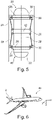
- FIG 5 shows the gas tank 22 in a front view approximately perpendicular to a spar 14.
- First fastening elements 36 can be seen here, which are coupled to the holding elements 30 by the tension elements 28 and fix the gas tank 22 essentially in the X and Y direction.
- the first fasteners 36 are found both at an upper first end portion 38 of the gas tank 22, as also on a lower, second end section 40 of the gas tank 22. They are, for example, ring-shaped and can have eyelets, flanges or other means in order to allow the tension elements 28 to be fastened.
- the holding elements 30 are arranged laterally adjacent to the first fastening elements 36 .
- the second fastening elements 26 are arranged centrally between the first end section 38 and the second end section 40 and are also clamped to the retaining elements 30 via tension elements 28 . They can also have an annular structure 42 via which they are connected to the gas tank 22 . In this way, in particular, a fixation in the z-direction can take place.
Landscapes
- Engineering & Computer Science (AREA)
- Aviation & Aerospace Engineering (AREA)
- Mechanical Engineering (AREA)
- Filling Or Discharging Of Gas Storage Vessels (AREA)
Abstract
Description
- Die Erfindung betrifft einen Strömungskörper für ein Luftfahrzeug und ein Luftfahrzeug mit mindestens einem derartigen Strömungskörper.
- Zur Versorgung von Luftfahrzeugen mit elektrischer Leistung können Brennstoffzellen eingesetzt werden, die die Zufuhr eines Treibstoffs, insbesondere von Wasserstoff oder einem Wasserstoff aufweisenden Gas, benötigen. Der Treibstoff kann durch Reformierung aus einem anderen Treibstoff erzeugt oder aus einem Wasserstofftank bereitgestellt werden. Letzterer könnte zur Aufnahme von gasförmigem oder flüssigem Wasserstoff ausgebildet sein.
- Aus
DE 10 2011 116 841 A1 ist ein Luftfahrzeug bekannt, das eine Brennstoffzelle und ein Wasserelektrolysegerät aufweist. Weiter weist es einen röhrenförmigen gasdichten Flügelholm auf, in dem ein Sauerstofftank bzw. ein Wasserstofftank angeordnet sind und der in gefülltem Zustand eine zusätzliche Versteifung des Tragflügels in Spannweitenrichtung bildet. Der Flügelholm kann ein Innenrohr aufweisen, das einen Innendruck des Wasserstoffs bzw. Sauerstoffs sowie auf den Flächenanteil am Holm entfallende Zug- und Druckkräfte aus dem Flügelbiegemoment und den Flügeldruckkräften aufnimmt. -
DE 10 2019 126 287 B3 offenbart einen Fluidtank zur Integration in eine Struktur eines unbemannten Fluggeräts, aufweisend eine Hülle mit einer ersten Axialwandung, einer entgegengesetzt angeordneten zweiten Axialwandung, einer Oberseite, einer Unterseite und einem umschlossenen Innenraum, mindestens eine Aufnahmekammer in dem Innenraum zum Lagern von Fluid, und eine an der Unterseite angeordnete Sammelkammer, die mit der mindestens einen Aufnahmekammer in Fluidverbindung steht, wobei die Sammelkammer eine Bodenfläche aufweist, durch die sich ein Ablauf erstreckt, und wobei eine Deckfläche oberhalb der Bodenfläche angeordnet ist und zumindest einen Abschnitt der Sammelkammer überdeckt. - Aufgabe der Erfindung ist es, eine alternative Vorrichtung zum Mitführen von Treibstoff und insbesondere Wasserstoff in einem Luftfahrzeug bereitzustellen.
- Die Aufgabe wird gelöst durch einen Strömungskörper für ein Luftfahrzeug mit den Merkmalen des unabhängigen Anspruchs 1. Vorteilhafte Ausführungsformen und Weiterbildungen sind den Unteransprüchen und der nachfolgenden Beschreibung zu entnehmen.
- Es wird ein Strömungskörper für ein Luftfahrzeug vorgeschlagen, aufweisend einen Torsionskasten mit mehreren Holmen und/oder Rippen und mindestens zwei Hautabschnitten zum Umhüllen der Holme und/oder Rippen, wobei in dem Torsionskasten mindestens eine Innenzelle ausgebildet ist. Es ist vorgesehen, dass in der mindestens einen Innenzelle ein Gastank mit einer Gastankhülle angeordnet ist, und dass der Gastank Befestigungselemente aufweist, die mit Halteelementen in der betreffenden Innenzelle gekoppelt sind, um den Gastank derart zu haltern, dass die Gastankhülle in einem Abstand zu den Holmen und/oder Rippen und den Hautabschnitten gelagert und in drei Raumrichtungen gestützt ist.
- Der Torsionskasten ist eine kastenförmige, weitgehend hohle Struktur, welche eine Kernkomponente des Strömungskörpers darstellen kann. Der Torsionskasten wird beim Betrieb des Strömungskörpers insbesondere auf Torsion und Biegung belastet und kann besonders bevorzugt mehrere, d.h. mindestens zwei, Holme aufweisen. Es sind dabei insbesondere Vielholmer-Gestaltungen vorteilhaft. Zwischen den Holmen, die voneinander beanstandet sind, könnten gegebenenfalls mehrere Rippen angeordnet sein. Dadurch kann sich eine lamellen- oder gitterförmige Struktur ergeben, welche von den Hautabschnitten umhüllt wird. Die Holme, Rippen und Hautabschnitte sind aneinander befestigt, sodass der Torsionskasten eine besonders große Steifigkeit aufweist. Ein solcher Torsionskasten ist beispielsweise als Flügelkasten bekannt, der auch in Seitenleitwerken, Höhenleitwerken, Winglets, Vorflügeln und anderen Elementen vorhanden sein kann.
- Aufgrund der genannten, kastenförmigen Struktur, die aus voneinander beabstandeten Versteifungselementen besteht, sind einzelne Innenzellen in dem Torsionskasten gebildet. Erfindungsgemäß ist in mindestens einer solchen Innenzelle ein Gastank mit einer Gastankhülle angeordnet und dazu ausgebildet, ein Gas aufzunehmen und bei Bedarf wieder abzugeben. Die Größe und Gestalt der einzelnen Innenzellen folgt der Konstruktion des Torsionskastens, der primär zum Erreichen einer gewünschten, aerodynamisch Oberfläche gestaltet ist. Die Innenzelle, d.h. der Hohlraum an sich, erfüllt oftmals keine weiteren Aufgaben. In Seitenleitwerken könnten Aktuatoren, elektrische Leitungen, Fluidleitungen oder Wellen durch Innenzellen verlaufen. Erfindungsgemäß wird nun zumindest eine dieser hohlen Innenzellen mit einem Gastank ausgestattet, sodass eine besonders gute Ausnutzung des zur Verfügung stehenden Bauraums innerhalb des Strömungskörpers und des Luftfahrzeugs erfolgt.
- Um zu verhindern, dass der Gastank beim Betrieb des Luftfahrzeugs den Strömungskörper beschädigt oder durch Trägheitskräfte aufgrund von Beschleunigungen des Luftfahrzeugs wiederholt mit einer inneren Begrenzungsfläche der betreffenden Innenzelle in Berührung gerät, ist eine Befestigung vorgesehen. Diese wird durch die Befestigungselemente realisiert, die an dem Gastank angeordnet sind. Die Befestigungselemente könnten direkt an der Gastankhülle angeordnet oder an Flanschen befestigt sein, die wiederum an der Gastankhülle angeordnet sind. Die Befestigungselemente sind mit Halteelementen in der betreffenden Innenzelle gekoppelt, sodass der Gastank daran gehaltert wird. Durch das Vorsehen eines ausreichenden Abstandes zu den Holmen und/oder Rippen sowie den Hautabschnitten kann eine Berührung ausgeschlossen werden. Der Abstand unterstützt zudem eine thermische Isolierung, was besonders für gekühlte und insbesondere kryogene Medien in dem Gastank vorteilhaft ist. Aufgrund der üblicherweise räumlichen Bewegung des Strömungskörpers ist es sinnvoll, den betreffenden Gastank in allen drei Raumrichtungen zu stützen. Die Befestigung ist dabei derart auszulegen, dass die erwarteten bzw. zulassungsrelevanten Beschleunigungen berücksichtigt werden.
- In einer vorteilhaften Ausführungsform ist der Gastank ein Druckgastank. Der Gastank kann folglich mit einem druckbeaufschlagten Gas befüllt werden. Der Gastank könnte einem herkömmlichen Druckgastank ähneln, der eine möglichst runde oder zumindest abgerundete Form aufweist. Die Gestaltungsmöglichkeit eines Drucktanks hängt jedoch von der Gestaltung der mindestens einen Innenzelle ab. Sind die Innenzellen beispielsweise eher schmal und länglich könnten sich röhrenförmige Drucktanks mit runden, stirnseitigen Endkappen anbieten.
- In einer besonders vorteilhaften Ausführungsform ist der Gastank dazu ausgebildet, flüssigen Wasserstoff zu lagern. Hierzu ist bevorzugt, dass der Gastank eine für die kryogene Lagerung von Wasserstoff ausreichende thermische Isolierung aufweist. Hierzu kann der Gastank eine Anordnung aus mehreren Gastankhüllen aufweisen, die gemeinsam einen Wärmeeintrag in den Gastank verzögern. Für die Realisierung einer solchen Isolierung kommen unterschiedliche Isolierschichten zwischen aufeinanderfolgenden Gastankhüllen in Betracht, welche unter anderem Vakuumisolierungen, Schäume und anderes umfassen.
- Besonders bevorzugt weist der Strömungskörper mehrere Innenzellen auf, in denen mehrere voneinander unabhängige Gastanks angeordnet sind. Die Innenzellen sind, je nach Ausführung des Strömungskörpers, nicht beliebig groß und können daher nicht beliebig große Gastanks aufnehmen. Zur Bereitstellung einer mechanischen Festigkeit können innen mehrere Holme oder Rippen vorgesehen sein, die eine Unterteilung des von dem Torsionskasten umschlossenen Volumens durchführen. Sollte demnach Bedarf an einem größeren Gasvolumen oder einer größeren Gasmasse bestehen, als in einer der Innenzellen in einem Gastank unterbringbar ist, können folglich auch mehrere Innenzellen jeweils mit einem Gastank ausgestattet werden. Es ist nicht unbedingt notwendig, die Gastanks auf identische Weise zu realisieren. Sollten die Innenzellen unterschiedliche Abmessungen aufweisen, könnten auch hierauf abgestimmte Gastanks realisiert werden. Durch ein Leitungssystem mit Anschlussstücken, Ventilen, einem Verteiler oder ähnlichem können die mehreren Gastanks das darin enthaltene Gas an eine einzige Leitung liefern oder durch eine einzige Leitung befüllt werden.
- Bei einer vorteilhaften Ausführungsform sind die Befestigungselemente an der Gastankhülle angeordnet oder damit gekoppelt, wobei die Befestigungselemente Zugelemente aufweisen, die mit den Halteelementen verbunden sind. Es ist vorstellbar, dass die Befestigungselemente an unterschiedlichen Abschnitten und unterschiedlichen Seiten eines Gastanks angeordnet sind, sodass eine stabile Halterung sowie eine gleichbleibende Ausrichtung des Gastanks ermöglicht wird. Die Halteelemente könnten an Versteifungsbauteilen, beispielsweise Holmen und/oder Rippen und/oder Hautabschnitten angeordnet sein. Aus Gründen der Festigkeit kann es sich anbieten, die Halteelemente in der Nähe von Kreuzungspunkten von Versteifungselementen anzuordnen. Da ein Gastank in einem Abstand zu allen Strukturkomponenten steht, die eine Innenzelle bilden, können Zugelemente den Abstand zwischen den Befestigungselementen und den Halteelementen überbrücken. Die Zugelemente können weiterhin Spannmittel aufweisen, durch die alle mit einem Gastank gekoppelten Zugelemente straff gespannt sind und nicht durchhängen. Somit wird der Gastank straff in der jeweiligen Innenzelle aufgehängt. Durch diese Aufhängung können auch unterschiedliche Wärmedehnungen des Gastanks und der Versteifungselemente kompensiert werden.
- In einer besonders vorteilhaften Ausführungsform sind die Zugelemente symmetrisch um mindestens eine Erstreckungsachse des Gastanks angeordnet. Eine solche Erstreckungsachse könnte beispielsweise eine Längsachse sein, um die herum die einzelnen Zugelemente symmetrisch angeordnet werden. Die Belastung der Zugelemente kann dann über alle Zugelemente gleichmäßig verteilt sein.
- Der Gastank könnte eine längliche Form aufweisen, wobei eine Haupterstreckungsachse parallel oder winkelsymmetrisch zu Längsversteifungselementen verläuft, die an den Hautabschnitten angeordnet sind. Eine Innenzelle könnte beispielsweise zwei voneinander beabstandete Holme oder zwei voneinander beabstandete Rippen aufweisen, zwischen denen der betreffende Gastank mit seiner Längsachse verläuft. Verlaufen die beiden Längsversteifungselemente parallel zueinander, könnte auch die Haupterstreckungsachse des Gastanks parallel hierzu verlaufen. Schließen die beiden Längsversteifungselemente einen Winkel zueinander ein, könnte die Haupterstreckungsachse zu jedem Längsversteifungselement denselben Winkelbetrag einschließen.
- Besonders bevorzugt wird die mindestens eine Innenzelle zumindest von zwei voneinander beabstandeten Holmen und den Hautabschnitten begrenzt. Folglich können mehrere Innenzellen jeweils von voneinander beabstandeten Holmen begrenzt sein, zwischen denen sich ein Gastank erstreckt.
- Es ist vorteilhaft, wenn der Gastank erste Befestigungselemente und zweite Befestigungselement aufweist, die mit Halteelementen in der betreffenden Innenzelle gekoppelt sind, wobei die ersten Befestigungselemente und die zweiten Befestigungselemente an zwei voneinander beabstandeten Abschnitten des Gastanks angebracht und zum Stützen in unterschiedliche Raumrichtungen ausgebildet sind. Hiermit könnte beispielsweise eine Längs- und Querbeschleunigung des Luftfahrzeugs, an dem der Strömungskörper angeordnet ist, mit dedizierten ersten Befestigungselementen abgefangen werden. Vertikalbeschleunigungen könnten indes durch zweite Befestigungselemente aufgenommen werden. Die Vertikalbeschleunigung könnte mittig an dem Gastank abgefangen werden, während die Längs- und Querbeschleunigungen an einander gegenüberliegenden Endabschnitten abgefangen werden könnten. Es sind jedoch auch andere Varianten denkbar, bei denen die Befestigungselemente umgekehrt hierzu angeordnet sind oder bei denen andere Kombinationen von Beschleunigungsanteilen berücksichtigt werden.
- Der Torsionskasten kann zwei, drei oder mehr ebene Kastenabschnitte aufweisen, die aneinandergereiht den Torsionskasten bilden, wobei in den Kastenabschnitten jeweils mehrere Innenzellen gebildet sind, wobei in jedem Kastenabschnitt mindestens eine Gruppen von Gastanks in den betreffenden Innenzellen angeordnet sind. Folglich könnten mehrere Ebenen von mehreren Gastanks nebeneinander in einem Torsionskasten angeordnet sein, um eine größere Anordnung von Gastanks zu schaffen. Hiermit könnten größere, komplexere Torsionskästen von größeren Strömungskörpern sinnvoll ausgefüllt werden.
- Der Strömungskörper könnte ein Seitenleitwerk oder ein Höhenleitwerk eines Flugzeugs sein. Insbesondere das Seitenleitwerk kann sich für das erfindungsgemäße Konzept anbieten, da dort mehrere hohle Innenzellen vorzufinden sind, die durch Ausstattung mit Gastanks sinnvoll genutzt werden können.
- Die Erfindung betrifft ferner ein Luftfahrzeug, aufweisend mindestens einen Strömungskörper nach der vorhergehenden Beschreibung.
- Weitere Merkmale, Vorteile und Anwendungsmöglichkeiten der vorliegenden Erfindung ergeben sich aus der nachfolgenden Beschreibung der Ausführungsbeispiele und den Figuren. Dabei bilden alle beschriebenen und/oder bildlich dargestellten Merkmale für sich und in beliebiger Kombination den Gegenstand der Erfindung auch unabhängig von ihrer Zusammensetzung in den einzelnen Ansprüchen oder deren Rückbezügen. In den Figuren stehen weiterhin gleiche Bezugszeichen für gleiche oder ähnliche Objekte.
-
Fig. 1 zeigt einen Strömungskörper als Seitenleitwerk in einer teilgeschnittenen Seitenansicht. -
Fig. 2 zeigt eine Vergrößerung der Ansicht ausFig. 1 . -
Fig. 3 zeigt eine Draufsicht auf einen Gastank in einer Innenzelle. -
Fig. 4 zeigt zwei Gastanks in zwei benachbarten Innenzellen. -
Fig. 5 zeigt eine Vorderansicht eines Gastanks in einer Innenzelle. -
Fig. 6 zeigt ein Luftfahrzeug mit einem erfindungsgemäß gestalteten Seitenleitwerk. -
Fig. 1 zeigt einen Strömungskörper in Form eines Seitenleitwerks 2. Zur Orientierung ist ein Koordinatensystem dargestellt, das eine Längsachse X, eine Querachse Y und eine Hochachse Z eines Luftfahrzeugs, an dem das Seitenleitwerk 2 angeordnet ist, zeigt. - Ein Torsionskasten 4 ist ein zentraler, Lasten aufnehmender Bestandteil des Strömungskörpers 2. An der Hinterkante 6 des Strömungskörpers 2 ist ein Scharnier 8 angeordnet, mit dem ein Seitenruder 10 bewegbar gelagert ist. An einer gegenüberliegenden Seite ist eine Vorderkante 12 vorgesehen. Der Torsionskasten 4 weist mehrere Holme 14 auf, die sich zwischen der Vorderkante 12 und der Hinterkante 6 mit einem sich nach oben verringernden Abstand erstrecken. Auf den Holmen 14 sind ein erster Hautabschnitt 16 (in der Zeichnungsebene durch die Holme 14 teilweise verdeckt) und einen zweiten Hautabschnitt (in dieser Ansicht weggelassen) angeordnet, die den Torsionskasten 4 schließen. Dadurch entstehen mehrere Innenzellen 18. Es ist vorstellbar, dass die Innenzellen 18 gegebenenfalls stellenweise durch Rippen (hier nicht dargestellt) unterteilt werden. An den Hauptabschnitten 16 sind zudem Längsversteifungselemente in Form von Stringern 20 angeordnet.
- An einem unteren Ende des Strömungskörpers 2 sind vier Gastanks 22 ersichtlich, die in separaten Innenzellen 18 angeordnet und dazu ausgebildet sind, ein Gas zu speichern. Dies kann insbesondere Wasserstoff sein. Die Gastanks 22 können beispielhaft dazu ausgebildet sein, flüssigen Wasserstoff kryogen zu lagern.
-
Fig. 2 zeigt die Anordnung der Gastanks 22 in einer vergrößerten Darstellung. Er ist ersichtlich, dass die Gastanks 22 länglich bzw. röhrenförmig sind und abgerundete Endkappen aufweisen. Sie besitzen jeweils eine Haupterstreckungsachse 24, die eine Längsachse darstellen kann, welche weitgehend parallel zu den Stringern 20 verlaufen. -
Fig. 3 zeigt eine Draufsicht eine zu der Erstreckungsachse 24 senkrechte Ebene eines Gastanks 22. Der Gastank 22 weist Befestigungselemente 26 auf, die über Zugelemente 28 mit Halteelementen 30 gekoppelt sind. Wie weiter nachfolgend erläutert wird, werden diese Befestigungselemente 26 auch als zweite Befestigungselemente bezeichnet. Die Halteelemente 30 können an Kreuzungspunkten zwischen Holmen 14 und dem ersten Hautabschnitt 16 bzw. einem gegenüberliegend angeordneten zweiten Hautabschnitt 32 positioniert und dort mit den Holmen 14 und den Hautabschnitten 16 und 32 verbunden sein. Die Zugelemente 28 sind dazu ausgebildet, den Gastank 22 an den Halteelementen 30 zu verspannen. Hierfür sind beispielhaft vier zweite Befestigungselemente 26 regelmäßig und symmetrisch um die Längserstreckungsachse 24 herum entlang des Umfangs des Gastanks 22 verteilt. Die Zugelemente 28 können ferner durch Auswahl eines geeigneten Materials und eines entsprechenden Dehnverhaltens dazu ausgebildet sein, eine Dämpfungswirkung zu erzielen. - Mehrere Gastanks 22 in benachbarten Innenzellen 18 sind in
Fig. 4 dargestellt. Hier ist ersichtlich, dass die Gastanks 22 einen bestimmten Abstand zu Innenflächen 34 der Innenzelle 18 aufweisen. Dadurch können Beschädigungen durch Anschlagen der Gastanks 22 an die Innenflächen 34 verhindert werden. Gleichzeitig könnte insbesondere bei der Verwendung kryogener Gastanks 22 ein Wärmeeintrag in die Gastanks 22 reduziert werden. -
Fig. 5 stellt den Gastank 22 in einer Vorderansicht etwa senkrecht zu einem Holm 14 dar. Hier sind erste Befestigungselemente 36 ersichtlich, die durch die Zugelemente 28 mit den Halteelementen 30 gekoppelt sind und eine Fixierung des Gastanks 22 im Wesentlichen in X- und Y-Richtung durchführen. Die ersten Befestigungselemente 36 finden sich sowohl an einem oberen ersten Endabschnitt 38 des Gastanks 22, als auch an einem unteren zweiten Endabschnitt 40 des Gastanks 22. Sie sind beispielhaft ringförmig ausgebildet und können Ösen, Flansche oder andere Mittel aufweisen, um eine Befestigung der Zugelemente 28 zu erlauben. Analog dazu sind die Halteelemente 30 seitlich benachbart zu den ersten Befestigungselementen 36 angeordnet. Die zweiten Befestigungselemente 26 sind mittig zwischen dem ersten Endabschnitt 38 und dem zweiten Endabschnitt 40 angeordnet und ebenso über Zugelemente 28 mit den Halteelementen 30 verspannt. Sie können ebenfalls eine ringförmige Struktur 42 aufweisen, über die sie mit dem Gastank 22 verbunden sind. Hierüber kann insbesondere eine Fixierung in der z-Richtung erfolgen. - Schließlich zeigt
Fig. 6 ein Luftfahrzeug 44, das ein Seitenleitwerk 2 aufweist, das nach den vorangehend dargestellten Prinzipien ausgestaltet ist. - Ergänzend sei darauf hingewiesen, dass "aufweisend" keine anderen Elemente oder Schritte ausschließt, und "ein" oder "eine" keine Vielzahl ausschließt. Ferner sei darauf hingewiesen, dass Merkmale, die mit Verweis auf eines der obigen Ausführungsbeispiele beschrieben worden sind, auch in Kombination mit anderen Merkmalen anderer oben beschriebener Ausführungsbeispiele verwendet werden können. Bezugszeichen in den Ansprüchen sind nicht als Einschränkung anzusehen.
-
- 2
- Strömungskörper / Seitenleitwerk
- 4
- Torsionskasten
- 6
- Hinterkante
- 8
- Scharnier
- 10
- Seitenruder
- 12
- Vorderkante
- 14
- Holm
- 16
- erster Hautab schnitt
- 18
- Innenzelle
- 20
- Stringer
- 22
- Gastank
- 24
- Haupterstreckungsachse
- 26
- zweites Befestigungselement
- 28
- Zugelement
- 30
- Halteelement
- 32
- zweiter Hautabschnitt
- 34
- Innenfläche
- 36
- erstes Befestigungselement
- 38
- erster Endabschnitt
- 40
- zweiter Endabschnitt
- 42
- ringförmige Struktur
- 44
- Luftfahrzeug
Claims (12)
- Strömungskörper (2) für ein Luftfahrzeug (44), aufweisendeinen Torsionskasten(4) mitmehreren Holmen (14) und/oderRippen undmindestens zwei Hautabschnitten (16, 32) zum Umhüllen der Holme (14) und/oder Rippen,wobei in dem Torsionskasten (4) mindestens eine Innenzelle (18) ausgebildet ist,dadurch gekennzeichnet, dass in der mindestens einen Innenzelle (18) ein Gastank (22) mit einer Gastankhülle angeordnet ist, unddass der Gastank (22) Befestigungselemente (26, 36) aufweist, die mit Halteelementen (30) in der betreffenden Innenzelle (18) gekoppelt sind, um den Gastank (22) derart zu haltern, dass die Gastankhülle in einem Abstand zu den Holmen (14) und/oder Rippen und den Hautabschnitten (16, 32) gelagert und in drei Raumrichtungen gestützt ist.
- Strömungskörper (2) nach Anspruch 1,
dadurch gekennzeichnet, dass der Gastank (22) ein Druckgastank ist. - Strömungskörper (2) nach Anspruch 1,
dadurch gekennzeichnet, dass der Gastank (22) dazu ausgebildet ist, flüssigen Wasserstoff zu lagern. - Strömungskörper (2) nach einem der vorhergehenden Ansprüche,
dadurch gekennzeichnet, dass der Strömungskörper (2) mehrere Innenzellen (18) aufweist, in denen mehrere voneinander unabhängige Gastanks (22) angeordnet sind. - Strömungskörper (2) nach einem der vorhergehenden Ansprüche,dadurch gekennzeichnet, dass die Befestigungselemente (26, 36) an der Gastankhülle angeordnet oder damit gekoppelt sind, unddass die Befestigungselemente (26, 36) Zugelemente (28) aufweisen, die mit den Halteelementen (30) verbunden sind.
- Strömungskörper (2) nach Anspruch 5,
dadurch gekennzeichnet, dass die die Zugelemente (28) symmetrisch um mindestens eine Erstreckungsachse (24) des Gastanks (22) angeordnet sind. - Strömungskörper (2) nach einem der vorhergehenden Ansprüche,
dadurch gekennzeichnet, dass der Gastank (22) eine längliche Form aufweist, wobei eine Haupterstreckungsachse (24) parallel oder winkelsymmetrisch zu Längsversteifungselementen (20) verläuft, die an den Hautabschnitten (16, 32) angeordnet sind. - Strömungskörper (2) nach einem der vorhergehenden Ansprüche,
dadurch gekennzeichnet, dass die mindestens eine Innenzelle (18) zumindest von zwei voneinander beabstandeten Holmen (14) und den Hautabschnitten (16, 32) begrenzt wird. - Strömungskörper (2) nach einem der vorhergehenden Ansprüche,dadurch gekennzeichnet, dass der Gastank (22) erste Befestigungselemente (36) und zweite Befestigungselemente (26) aufweist, die mit Halteelementen (30) in der betreffenden Innenzelle (18) gekoppelt sind,wobei die ersten Befestigungselemente (36) und die zweiten Befestigungselemente (26) an zwei voneinander beabstandeten Längsabschnitten (38, 40) des Gastanks (22) angebracht sind und zum Stützen in unterschiedliche Raumrichtungen ausgebildet sind.
- Strömungskörper (2) nach einem der vorhergehenden Ansprüche,
dadurch gekennzeichnet, dass der Torsionskasten (4) zwei, drei oder mehr ebene Kastenabschnitte aufweist, die aneinandergereiht den Torsionskasten (4) bilden, wobei in den Kastenabschnitten jeweils mehrere Innenzellen (18) gebildet sind, wobei in jedem Kastenabschnitt mindestens eine Gruppen von Gastanks (22) in den betreffenden Innenzellen (18) angeordnet sind. - Strömungskörper (2) nach einem der vorhergehenden Ansprüche,
dadurch gekennzeichnet, dass der Strömungskörper (2) ein Seitenleitwerk oder ein Höhenleitwerk eines Flugzeugs (44) ist. - Luftfahrzeug (44), aufweisend mindestens einen Strömungskörper (2) nach einem der vorhergehenden Ansprüche.
Applications Claiming Priority (1)
| Application Number | Priority Date | Filing Date | Title |
|---|---|---|---|
| DE102021105609.8A DE102021105609A1 (de) | 2021-03-09 | 2021-03-09 | Strömungskörper für ein Luftfahrzeug mit integriertem Gastank |
Publications (2)
| Publication Number | Publication Date |
|---|---|
| EP4056478A1 true EP4056478A1 (de) | 2022-09-14 |
| EP4056478B1 EP4056478B1 (de) | 2024-04-03 |
Family
ID=80446061
Family Applications (1)
| Application Number | Title | Priority Date | Filing Date |
|---|---|---|---|
| EP22157774.5A Active EP4056478B1 (de) | 2021-03-09 | 2022-02-21 | Strömungskörper für ein luftfahrzeug mit integriertem gastank |
Country Status (4)
| Country | Link |
|---|---|
| US (1) | US11945599B2 (de) |
| EP (1) | EP4056478B1 (de) |
| CN (1) | CN115042953A (de) |
| DE (1) | DE102021105609A1 (de) |
Families Citing this family (6)
| Publication number | Priority date | Publication date | Assignee | Title |
|---|---|---|---|---|
| GB2604140A (en) * | 2021-02-25 | 2022-08-31 | Airbus Operations Ltd | Wingbox with fuel tank attached to ribs |
| EP4349716A1 (de) * | 2022-10-05 | 2024-04-10 | Airbus S.A.S. | Flugzeug mit hängendem wasserstofftank |
| FR3141682A1 (fr) * | 2022-11-08 | 2024-05-10 | Airbus Operations | Système de fixation pour aéronef destiné à fixer au moins un réservoir prévu pour contenir de l’hydrogène liquide autorisant un accès facile au réservoir. |
| EP4640563A1 (de) * | 2024-04-23 | 2025-10-29 | Airbus Operations GmbH | Rumpfabschnitt, flugzeug und verfahren |
| WO2026009427A1 (ja) * | 2024-07-05 | 2026-01-08 | 株式会社Twfインダストリイ | 高圧ガスタンクを内包する翼型構造物とその製造方法 |
| CN120003697B (zh) * | 2025-03-10 | 2025-10-10 | 哈尔滨工业大学 | 一种用于轻质隔热储油机翼/舵翼的多模块串联油箱 |
Citations (6)
| Publication number | Priority date | Publication date | Assignee | Title |
|---|---|---|---|---|
| DE102011116841A1 (de) | 2011-10-25 | 2013-04-25 | Eads Deutschland Gmbh | Höhenluftfahrzeug, Luftfahrzeugverband und Verfahren zum Betreiben eines Luftfahrzeugverbands |
| EP2639152A2 (de) * | 2012-03-14 | 2013-09-18 | The Boeing Company | Anbringung von Flugzeugrippen an Holme mit variabler Geometrie |
| US20150069184A1 (en) * | 2013-09-12 | 2015-03-12 | The Boeing Company | Cryogenic fuel tanks for use in aircraft structures |
| US20170081039A1 (en) * | 2014-05-07 | 2017-03-23 | Bae Systems Plc | Liquid storage system |
| CN106628114B (zh) * | 2016-10-10 | 2020-06-09 | 北京航空航天大学 | 一种一体化无人机机翼 |
| DE102019126287B3 (de) | 2019-09-30 | 2021-01-14 | Airbus Defence and Space GmbH | Fluidtank zur Integration in eine Struktur eines unbemannten Fluggeräts |
Family Cites Families (5)
| Publication number | Priority date | Publication date | Assignee | Title |
|---|---|---|---|---|
| GB1221911A (en) * | 1969-03-31 | 1971-02-10 | Shell Int Research | Tank for liquid cargo |
| US4448372A (en) * | 1981-09-30 | 1984-05-15 | The Boeing Company | Aircraft vertical fin-fuselage structural integration system |
| BRPI0520590A2 (pt) * | 2005-09-29 | 2009-05-19 | Airbus Espana Sl | método de proteção de tanques de combustìvel fabricados com materiais compostos contra descargas elétricas |
| US10800525B2 (en) * | 2013-05-20 | 2020-10-13 | The Boeing Company | Efficient low carbon emission airplane integrating jet fuel and cryogenic fuel systems |
| US10457391B2 (en) * | 2016-03-15 | 2019-10-29 | Selex Galileo Inc. | Method and system for a small unmanned aerial system for delivering electronic warfare and cyber effects |
-
2021
- 2021-03-09 DE DE102021105609.8A patent/DE102021105609A1/de active Pending
-
2022
- 2022-02-21 EP EP22157774.5A patent/EP4056478B1/de active Active
- 2022-03-09 CN CN202210232021.0A patent/CN115042953A/zh active Pending
- 2022-03-09 US US17/690,329 patent/US11945599B2/en active Active
Patent Citations (6)
| Publication number | Priority date | Publication date | Assignee | Title |
|---|---|---|---|---|
| DE102011116841A1 (de) | 2011-10-25 | 2013-04-25 | Eads Deutschland Gmbh | Höhenluftfahrzeug, Luftfahrzeugverband und Verfahren zum Betreiben eines Luftfahrzeugverbands |
| EP2639152A2 (de) * | 2012-03-14 | 2013-09-18 | The Boeing Company | Anbringung von Flugzeugrippen an Holme mit variabler Geometrie |
| US20150069184A1 (en) * | 2013-09-12 | 2015-03-12 | The Boeing Company | Cryogenic fuel tanks for use in aircraft structures |
| US20170081039A1 (en) * | 2014-05-07 | 2017-03-23 | Bae Systems Plc | Liquid storage system |
| CN106628114B (zh) * | 2016-10-10 | 2020-06-09 | 北京航空航天大学 | 一种一体化无人机机翼 |
| DE102019126287B3 (de) | 2019-09-30 | 2021-01-14 | Airbus Defence and Space GmbH | Fluidtank zur Integration in eine Struktur eines unbemannten Fluggeräts |
Also Published As
| Publication number | Publication date |
|---|---|
| EP4056478B1 (de) | 2024-04-03 |
| CN115042953A (zh) | 2022-09-13 |
| DE102021105609A1 (de) | 2022-09-15 |
| US11945599B2 (en) | 2024-04-02 |
| US20220289401A1 (en) | 2022-09-15 |
Similar Documents
| Publication | Publication Date | Title |
|---|---|---|
| EP4056478B1 (de) | Strömungskörper für ein luftfahrzeug mit integriertem gastank | |
| DE4018749C2 (de) | ||
| DE102014107316A1 (de) | Tanksystem zur kryogenen Lagerung von Wasserstoff und Flugzeug mit einem Tanksystem zur kryogenen Lagerung von Wasserstoff | |
| DE102019101728B4 (de) | Struktur zum Befestigen einer elektrischen Vorrichtung | |
| EP3037608A1 (de) | Montagesystem für modulare Industrieanlagen | |
| EP3022116B1 (de) | Veränderbares flügelprofil | |
| DE1052253B (de) | Aufhaengevorrichtung fuer Strahltriebwerke | |
| DE102018123531B4 (de) | Verfahren zum Installieren von Systemkomponenten in einem Abschnitt eines Flugzeugrumpfs | |
| DE202014003727U1 (de) | Multifunktionaler Ausleger mit zumindest einem Antrieb, insbesondere zur Verwendung in einem Multikoptersystem | |
| DE102009020896B4 (de) | Flugkörper | |
| DE1481217A1 (de) | Luftschiffgeruest | |
| WO2016184976A1 (de) | Vorrichtung zum transportieren von gasen | |
| DE3508101A1 (de) | Hybrid-flugzeug | |
| DE102019203607A1 (de) | Batteriemodul und Kraftfahrzeug | |
| EP4382434B1 (de) | Montagesystem und verfahren zur montage von flugzeugsystemkomponenten im dreiecksbereich | |
| WO2021063457A1 (de) | Fluidtank zur integration in eine struktur eines unbemannten fluggeräts | |
| DE19735641C2 (de) | Verfahren zur Herstellung einer Tragzelle eines Luftschiffs | |
| AT527684B1 (de) | Vorrichtung zur elektrischen Energieversorgung eines Fahrzeugs | |
| EP3663574B1 (de) | Transportvorrichtung für eine rotornabe einer windenergieanlage | |
| DE102022001312A1 (de) | Elektrischer Energiespeicher | |
| DE102015110536B4 (de) | Luftschiff | |
| DE2546477C2 (de) | Schiffstank zum Speichern oder Transportieren eines unter Druck stehenden fließfähigen Mediums | |
| DE102019126592A1 (de) | Unterbodenbaugruppe für ein Kraftfahrzeug und Kraftfahrzeug | |
| DE102022120790A1 (de) | Mehrwandiges Batteriegehäuse mit einem Hohlprofil | |
| DE102024100860A1 (de) | Brennstoffzellensystem |
Legal Events
| Date | Code | Title | Description |
|---|---|---|---|
| PUAI | Public reference made under article 153(3) epc to a published international application that has entered the european phase |
Free format text: ORIGINAL CODE: 0009012 |
|
| STAA | Information on the status of an ep patent application or granted ep patent |
Free format text: STATUS: THE APPLICATION HAS BEEN PUBLISHED |
|
| AK | Designated contracting states |
Kind code of ref document: A1 Designated state(s): AL AT BE BG CH CY CZ DE DK EE ES FI FR GB GR HR HU IE IS IT LI LT LU LV MC MK MT NL NO PL PT RO RS SE SI SK SM TR |
|
| STAA | Information on the status of an ep patent application or granted ep patent |
Free format text: STATUS: REQUEST FOR EXAMINATION WAS MADE |
|
| 17P | Request for examination filed |
Effective date: 20230125 |
|
| RBV | Designated contracting states (corrected) |
Designated state(s): AL AT BE BG CH CY CZ DE DK EE ES FI FR GB GR HR HU IE IS IT LI LT LU LV MC MK MT NL NO PL PT RO RS SE SI SK SM TR |
|
| GRAP | Despatch of communication of intention to grant a patent |
Free format text: ORIGINAL CODE: EPIDOSNIGR1 |
|
| STAA | Information on the status of an ep patent application or granted ep patent |
Free format text: STATUS: GRANT OF PATENT IS INTENDED |
|
| INTG | Intention to grant announced |
Effective date: 20231208 |
|
| GRAS | Grant fee paid |
Free format text: ORIGINAL CODE: EPIDOSNIGR3 |
|
| GRAA | (expected) grant |
Free format text: ORIGINAL CODE: 0009210 |
|
| STAA | Information on the status of an ep patent application or granted ep patent |
Free format text: STATUS: THE PATENT HAS BEEN GRANTED |
|
| AK | Designated contracting states |
Kind code of ref document: B1 Designated state(s): AL AT BE BG CH CY CZ DE DK EE ES FI FR GB GR HR HU IE IS IT LI LT LU LV MC MK MT NL NO PL PT RO RS SE SI SK SM TR |
|
| REG | Reference to a national code |
Ref country code: CH Ref legal event code: EP |
|
| REG | Reference to a national code |
Ref country code: IE Ref legal event code: FG4D Free format text: LANGUAGE OF EP DOCUMENT: GERMAN |
|
| REG | Reference to a national code |
Ref country code: DE Ref legal event code: R096 Ref document number: 502022000690 Country of ref document: DE |
|
| REG | Reference to a national code |
Ref country code: LT Ref legal event code: MG9D |
|
| REG | Reference to a national code |
Ref country code: NL Ref legal event code: MP Effective date: 20240403 |
|
| PG25 | Lapsed in a contracting state [announced via postgrant information from national office to epo] |
Ref country code: NL Free format text: LAPSE BECAUSE OF FAILURE TO SUBMIT A TRANSLATION OF THE DESCRIPTION OR TO PAY THE FEE WITHIN THE PRESCRIBED TIME-LIMIT Effective date: 20240403 |
|
| PG25 | Lapsed in a contracting state [announced via postgrant information from national office to epo] |
Ref country code: NL Free format text: LAPSE BECAUSE OF FAILURE TO SUBMIT A TRANSLATION OF THE DESCRIPTION OR TO PAY THE FEE WITHIN THE PRESCRIBED TIME-LIMIT Effective date: 20240403 |
|
| PG25 | Lapsed in a contracting state [announced via postgrant information from national office to epo] |
Ref country code: IS Free format text: LAPSE BECAUSE OF FAILURE TO SUBMIT A TRANSLATION OF THE DESCRIPTION OR TO PAY THE FEE WITHIN THE PRESCRIBED TIME-LIMIT Effective date: 20240803 |
|
| PG25 | Lapsed in a contracting state [announced via postgrant information from national office to epo] |
Ref country code: BG Free format text: LAPSE BECAUSE OF FAILURE TO SUBMIT A TRANSLATION OF THE DESCRIPTION OR TO PAY THE FEE WITHIN THE PRESCRIBED TIME-LIMIT Effective date: 20240403 |
|
| PG25 | Lapsed in a contracting state [announced via postgrant information from national office to epo] |
Ref country code: HR Free format text: LAPSE BECAUSE OF FAILURE TO SUBMIT A TRANSLATION OF THE DESCRIPTION OR TO PAY THE FEE WITHIN THE PRESCRIBED TIME-LIMIT Effective date: 20240403 Ref country code: FI Free format text: LAPSE BECAUSE OF FAILURE TO SUBMIT A TRANSLATION OF THE DESCRIPTION OR TO PAY THE FEE WITHIN THE PRESCRIBED TIME-LIMIT Effective date: 20240403 |
|
| PG25 | Lapsed in a contracting state [announced via postgrant information from national office to epo] |
Ref country code: GR Free format text: LAPSE BECAUSE OF FAILURE TO SUBMIT A TRANSLATION OF THE DESCRIPTION OR TO PAY THE FEE WITHIN THE PRESCRIBED TIME-LIMIT Effective date: 20240704 |
|
| PG25 | Lapsed in a contracting state [announced via postgrant information from national office to epo] |
Ref country code: PT Free format text: LAPSE BECAUSE OF FAILURE TO SUBMIT A TRANSLATION OF THE DESCRIPTION OR TO PAY THE FEE WITHIN THE PRESCRIBED TIME-LIMIT Effective date: 20240805 |
|
| PG25 | Lapsed in a contracting state [announced via postgrant information from national office to epo] |
Ref country code: ES Free format text: LAPSE BECAUSE OF FAILURE TO SUBMIT A TRANSLATION OF THE DESCRIPTION OR TO PAY THE FEE WITHIN THE PRESCRIBED TIME-LIMIT Effective date: 20240403 |
|
| PG25 | Lapsed in a contracting state [announced via postgrant information from national office to epo] |
Ref country code: CZ Free format text: LAPSE BECAUSE OF FAILURE TO SUBMIT A TRANSLATION OF THE DESCRIPTION OR TO PAY THE FEE WITHIN THE PRESCRIBED TIME-LIMIT Effective date: 20240403 |
|
| PG25 | Lapsed in a contracting state [announced via postgrant information from national office to epo] |
Ref country code: PL Free format text: LAPSE BECAUSE OF FAILURE TO SUBMIT A TRANSLATION OF THE DESCRIPTION OR TO PAY THE FEE WITHIN THE PRESCRIBED TIME-LIMIT Effective date: 20240403 |
|
| PG25 | Lapsed in a contracting state [announced via postgrant information from national office to epo] |
Ref country code: LV Free format text: LAPSE BECAUSE OF FAILURE TO SUBMIT A TRANSLATION OF THE DESCRIPTION OR TO PAY THE FEE WITHIN THE PRESCRIBED TIME-LIMIT Effective date: 20240403 |
|
| PG25 | Lapsed in a contracting state [announced via postgrant information from national office to epo] |
Ref country code: PT Free format text: LAPSE BECAUSE OF FAILURE TO SUBMIT A TRANSLATION OF THE DESCRIPTION OR TO PAY THE FEE WITHIN THE PRESCRIBED TIME-LIMIT Effective date: 20240805 Ref country code: PL Free format text: LAPSE BECAUSE OF FAILURE TO SUBMIT A TRANSLATION OF THE DESCRIPTION OR TO PAY THE FEE WITHIN THE PRESCRIBED TIME-LIMIT Effective date: 20240403 Ref country code: NO Free format text: LAPSE BECAUSE OF FAILURE TO SUBMIT A TRANSLATION OF THE DESCRIPTION OR TO PAY THE FEE WITHIN THE PRESCRIBED TIME-LIMIT Effective date: 20240703 Ref country code: LV Free format text: LAPSE BECAUSE OF FAILURE TO SUBMIT A TRANSLATION OF THE DESCRIPTION OR TO PAY THE FEE WITHIN THE PRESCRIBED TIME-LIMIT Effective date: 20240403 Ref country code: IS Free format text: LAPSE BECAUSE OF FAILURE TO SUBMIT A TRANSLATION OF THE DESCRIPTION OR TO PAY THE FEE WITHIN THE PRESCRIBED TIME-LIMIT Effective date: 20240803 Ref country code: HR Free format text: LAPSE BECAUSE OF FAILURE TO SUBMIT A TRANSLATION OF THE DESCRIPTION OR TO PAY THE FEE WITHIN THE PRESCRIBED TIME-LIMIT Effective date: 20240403 Ref country code: GR Free format text: LAPSE BECAUSE OF FAILURE TO SUBMIT A TRANSLATION OF THE DESCRIPTION OR TO PAY THE FEE WITHIN THE PRESCRIBED TIME-LIMIT Effective date: 20240704 Ref country code: FI Free format text: LAPSE BECAUSE OF FAILURE TO SUBMIT A TRANSLATION OF THE DESCRIPTION OR TO PAY THE FEE WITHIN THE PRESCRIBED TIME-LIMIT Effective date: 20240403 Ref country code: ES Free format text: LAPSE BECAUSE OF FAILURE TO SUBMIT A TRANSLATION OF THE DESCRIPTION OR TO PAY THE FEE WITHIN THE PRESCRIBED TIME-LIMIT Effective date: 20240403 Ref country code: CZ Free format text: LAPSE BECAUSE OF FAILURE TO SUBMIT A TRANSLATION OF THE DESCRIPTION OR TO PAY THE FEE WITHIN THE PRESCRIBED TIME-LIMIT Effective date: 20240403 Ref country code: BG Free format text: LAPSE BECAUSE OF FAILURE TO SUBMIT A TRANSLATION OF THE DESCRIPTION OR TO PAY THE FEE WITHIN THE PRESCRIBED TIME-LIMIT Effective date: 20240403 Ref country code: RS Free format text: LAPSE BECAUSE OF FAILURE TO SUBMIT A TRANSLATION OF THE DESCRIPTION OR TO PAY THE FEE WITHIN THE PRESCRIBED TIME-LIMIT Effective date: 20240703 |
|
| REG | Reference to a national code |
Ref country code: DE Ref legal event code: R097 Ref document number: 502022000690 Country of ref document: DE |
|
| PG25 | Lapsed in a contracting state [announced via postgrant information from national office to epo] |
Ref country code: DK Free format text: LAPSE BECAUSE OF FAILURE TO SUBMIT A TRANSLATION OF THE DESCRIPTION OR TO PAY THE FEE WITHIN THE PRESCRIBED TIME-LIMIT Effective date: 20240403 |
|
| PG25 | Lapsed in a contracting state [announced via postgrant information from national office to epo] |
Ref country code: EE Free format text: LAPSE BECAUSE OF FAILURE TO SUBMIT A TRANSLATION OF THE DESCRIPTION OR TO PAY THE FEE WITHIN THE PRESCRIBED TIME-LIMIT Effective date: 20240403 |
|
| PG25 | Lapsed in a contracting state [announced via postgrant information from national office to epo] |
Ref country code: RO Free format text: LAPSE BECAUSE OF FAILURE TO SUBMIT A TRANSLATION OF THE DESCRIPTION OR TO PAY THE FEE WITHIN THE PRESCRIBED TIME-LIMIT Effective date: 20240403 Ref country code: SK Free format text: LAPSE BECAUSE OF FAILURE TO SUBMIT A TRANSLATION OF THE DESCRIPTION OR TO PAY THE FEE WITHIN THE PRESCRIBED TIME-LIMIT Effective date: 20240403 |
|
| PG25 | Lapsed in a contracting state [announced via postgrant information from national office to epo] |
Ref country code: SM Free format text: LAPSE BECAUSE OF FAILURE TO SUBMIT A TRANSLATION OF THE DESCRIPTION OR TO PAY THE FEE WITHIN THE PRESCRIBED TIME-LIMIT Effective date: 20240403 |
|
| PG25 | Lapsed in a contracting state [announced via postgrant information from national office to epo] |
Ref country code: SM Free format text: LAPSE BECAUSE OF FAILURE TO SUBMIT A TRANSLATION OF THE DESCRIPTION OR TO PAY THE FEE WITHIN THE PRESCRIBED TIME-LIMIT Effective date: 20240403 Ref country code: SK Free format text: LAPSE BECAUSE OF FAILURE TO SUBMIT A TRANSLATION OF THE DESCRIPTION OR TO PAY THE FEE WITHIN THE PRESCRIBED TIME-LIMIT Effective date: 20240403 Ref country code: RO Free format text: LAPSE BECAUSE OF FAILURE TO SUBMIT A TRANSLATION OF THE DESCRIPTION OR TO PAY THE FEE WITHIN THE PRESCRIBED TIME-LIMIT Effective date: 20240403 Ref country code: EE Free format text: LAPSE BECAUSE OF FAILURE TO SUBMIT A TRANSLATION OF THE DESCRIPTION OR TO PAY THE FEE WITHIN THE PRESCRIBED TIME-LIMIT Effective date: 20240403 Ref country code: DK Free format text: LAPSE BECAUSE OF FAILURE TO SUBMIT A TRANSLATION OF THE DESCRIPTION OR TO PAY THE FEE WITHIN THE PRESCRIBED TIME-LIMIT Effective date: 20240403 |
|
| PLBE | No opposition filed within time limit |
Free format text: ORIGINAL CODE: 0009261 |
|
| STAA | Information on the status of an ep patent application or granted ep patent |
Free format text: STATUS: NO OPPOSITION FILED WITHIN TIME LIMIT |
|
| 26N | No opposition filed |
Effective date: 20250106 |
|
| PG25 | Lapsed in a contracting state [announced via postgrant information from national office to epo] |
Ref country code: SI Free format text: LAPSE BECAUSE OF FAILURE TO SUBMIT A TRANSLATION OF THE DESCRIPTION OR TO PAY THE FEE WITHIN THE PRESCRIBED TIME-LIMIT Effective date: 20240403 |
|
| PG25 | Lapsed in a contracting state [announced via postgrant information from national office to epo] |
Ref country code: SE Free format text: LAPSE BECAUSE OF FAILURE TO SUBMIT A TRANSLATION OF THE DESCRIPTION OR TO PAY THE FEE WITHIN THE PRESCRIBED TIME-LIMIT Effective date: 20240403 |
|
| PG25 | Lapsed in a contracting state [announced via postgrant information from national office to epo] |
Ref country code: MC Free format text: LAPSE BECAUSE OF FAILURE TO SUBMIT A TRANSLATION OF THE DESCRIPTION OR TO PAY THE FEE WITHIN THE PRESCRIBED TIME-LIMIT Effective date: 20240403 |
|
| REG | Reference to a national code |
Ref country code: CH Ref legal event code: PL |
|
| PG25 | Lapsed in a contracting state [announced via postgrant information from national office to epo] |
Ref country code: LU Free format text: LAPSE BECAUSE OF NON-PAYMENT OF DUE FEES Effective date: 20250221 |
|
| PG25 | Lapsed in a contracting state [announced via postgrant information from national office to epo] |
Ref country code: CH Free format text: LAPSE BECAUSE OF NON-PAYMENT OF DUE FEES Effective date: 20250228 |
|
| REG | Reference to a national code |
Ref country code: BE Ref legal event code: MM Effective date: 20250228 |
|
| PG25 | Lapsed in a contracting state [announced via postgrant information from national office to epo] |
Ref country code: BE Free format text: LAPSE BECAUSE OF NON-PAYMENT OF DUE FEES Effective date: 20250228 |
|
| PG25 | Lapsed in a contracting state [announced via postgrant information from national office to epo] |
Ref country code: IE Free format text: LAPSE BECAUSE OF NON-PAYMENT OF DUE FEES Effective date: 20250221 |
|
| PG25 | Lapsed in a contracting state [announced via postgrant information from national office to epo] |
Ref country code: IT Free format text: LAPSE BECAUSE OF FAILURE TO SUBMIT A TRANSLATION OF THE DESCRIPTION OR TO PAY THE FEE WITHIN THE PRESCRIBED TIME-LIMIT Effective date: 20240403 |
|
| PGFP | Annual fee paid to national office [announced via postgrant information from national office to epo] |
Ref country code: GB Payment date: 20260220 Year of fee payment: 5 |
|
| PGFP | Annual fee paid to national office [announced via postgrant information from national office to epo] |
Ref country code: DE Payment date: 20260218 Year of fee payment: 5 |
|
| PGFP | Annual fee paid to national office [announced via postgrant information from national office to epo] |
Ref country code: AT Payment date: 20260301 Year of fee payment: 5 |
|
| PGFP | Annual fee paid to national office [announced via postgrant information from national office to epo] |
Ref country code: FR Payment date: 20260219 Year of fee payment: 5 |