EP4055890B1 - Schätzung von signalabschattungsobstruktionen und signalreflektoren in einem drahtlosen kommunikationsnetz - Google Patents
Schätzung von signalabschattungsobstruktionen und signalreflektoren in einem drahtlosen kommunikationsnetz Download PDFInfo
- Publication number
- EP4055890B1 EP4055890B1 EP20894764.8A EP20894764A EP4055890B1 EP 4055890 B1 EP4055890 B1 EP 4055890B1 EP 20894764 A EP20894764 A EP 20894764A EP 4055890 B1 EP4055890 B1 EP 4055890B1
- Authority
- EP
- European Patent Office
- Prior art keywords
- ues
- shadowing
- nlos
- signal
- los
- Prior art date
- Legal status (The legal status is an assumption and is not a legal conclusion. Google has not performed a legal analysis and makes no representation as to the accuracy of the status listed.)
- Active
Links
Images


Classifications
-
- H—ELECTRICITY
- H04—ELECTRIC COMMUNICATION TECHNIQUE
- H04L—TRANSMISSION OF DIGITAL INFORMATION, e.g. TELEGRAPHIC COMMUNICATION
- H04L1/00—Arrangements for detecting or preventing errors in the information received
- H04L1/0001—Systems modifying transmission characteristics according to link quality, e.g. power backoff
- H04L1/0002—Systems modifying transmission characteristics according to link quality, e.g. power backoff by adapting the transmission rate
- H04L1/0003—Systems modifying transmission characteristics according to link quality, e.g. power backoff by adapting the transmission rate by switching between different modulation schemes
-
- H—ELECTRICITY
- H04—ELECTRIC COMMUNICATION TECHNIQUE
- H04W—WIRELESS COMMUNICATION NETWORKS
- H04W16/00—Network planning, e.g. coverage or traffic planning tools; Network deployment, e.g. resource partitioning or cells structures
- H04W16/24—Cell structures
-
- H—ELECTRICITY
- H04—ELECTRIC COMMUNICATION TECHNIQUE
- H04W—WIRELESS COMMUNICATION NETWORKS
- H04W24/00—Supervisory, monitoring or testing arrangements
- H04W24/04—Arrangements for maintaining operational condition
-
- H—ELECTRICITY
- H04—ELECTRIC COMMUNICATION TECHNIQUE
- H04W—WIRELESS COMMUNICATION NETWORKS
- H04W36/00—Hand-off or reselection arrangements
- H04W36/16—Performing reselection for specific purposes
-
- H—ELECTRICITY
- H04—ELECTRIC COMMUNICATION TECHNIQUE
- H04W—WIRELESS COMMUNICATION NETWORKS
- H04W64/00—Locating users or terminals or network equipment for network management purposes, e.g. mobility management
- H04W64/006—Locating users or terminals or network equipment for network management purposes, e.g. mobility management with additional information processing, e.g. for direction or speed determination
-
- H—ELECTRICITY
- H04—ELECTRIC COMMUNICATION TECHNIQUE
- H04L—TRANSMISSION OF DIGITAL INFORMATION, e.g. TELEGRAPHIC COMMUNICATION
- H04L1/00—Arrangements for detecting or preventing errors in the information received
- H04L1/0001—Systems modifying transmission characteristics according to link quality, e.g. power backoff
- H04L1/0009—Systems modifying transmission characteristics according to link quality, e.g. power backoff by adapting the channel coding
-
- H—ELECTRICITY
- H04—ELECTRIC COMMUNICATION TECHNIQUE
- H04W—WIRELESS COMMUNICATION NETWORKS
- H04W8/00—Network data management
- H04W8/005—Discovery of network devices, e.g. terminals
-
- H—ELECTRICITY
- H04—ELECTRIC COMMUNICATION TECHNIQUE
- H04W—WIRELESS COMMUNICATION NETWORKS
- H04W92/00—Interfaces specially adapted for wireless communication networks
- H04W92/16—Interfaces between hierarchically similar devices
- H04W92/18—Interfaces between hierarchically similar devices between terminal devices
Definitions
- the present disclosure relates generally to wireless communications, and in particular embodiments, to systems and methods for estimating locations of signal shadowing obstructions and signal reflectors in a wireless communications network.
- obstructions such as buildings and natural geographic features may reflect, scatter, or shadow signals propagating between transmitters and receivers in the network. These obstructions may be considered to be passive in the sense that the signals neither originate from nor terminate at these obstructions.
- a lack of knowledge of the location and extent of obstructions makes beamforming an essentially blind process that can only react when weak transmissions or complete transmission failures occur.
- Transmission beamforming is currently implemented as an analog beam-steering process where beams of fixed beam width are steered through the environment by adjustment of antenna phases at the transmitting antennas.
- Beam-steering is essentially a time-sharing process where the transmitter dwells at each angular segment for a time period to transmit to user equipment (UE) within the segment before moving on to the next segment.
- UE user equipment
- SNR signal-to-noise ratio
- the transmitter may compensate after the BER increase occurs by increasing the transmitted power, however this only addresses the problem after the fact.
- data packets may be dropped or delayed, a problem that is currently remedied by imposing a feedback overhead on the network to cause the transmitted power to be reactively increased.
- Cellular networks often operate in regions that have numerous obstructions that contribute toward a highly multipath transmission environment.
- the obstructions not only reflect the propagating signals between transmitters and receivers, but can also attenuate or completely block the signals.
- the RF signal attenuation due to obstructions can be greater than path loss effects due to the propagation distance of the signal.
- the cell size in cellular networks has been reduced. Additionally, for highly mobile UEs, it is necessary to hand off communications between base stations more frequently to ensure that the UEs connectivity is not interrupted. The handoff process is typically managed at network equipment remote from the transmitter, which causes additional delays and burdens the network because the UEs are supposed to remain unaware of the detachment/re-attachment processes.
- Shadowing impacts communications through intermittent power budget loss due to communication links being attenuated by large and small obstructions. Reflection
- Locations of some shadowing and reflecting obstructions may be established by employing sensing techniques such as satellite images, video image scanning, infrared imaging, RADAR, LIDAR, etc.
- sensing techniques such as satellite images, video image scanning, infrared imaging, RADAR, LIDAR, etc.
- implementation of these techniques would be costly and also un-scalable.
- simply determining physical locations of obstructions may not provide the information necessary for communication at cellular radio frequencies. Obstructions will vary considerably depending on their composition, such as the amount of steel reinforcing in a concrete building vs. a wood building, for example.
- the signal transmission effects of obstructions on microwave and mmWave communications might be difficult to determine based on only the physical location of the obstructions established by light, ultrasound, terahertz waves, etc. used in the above sensing techniques.
- Document EP 3 354 069 A1 discloses a base station which serves one or more terminals, requests a sidelink discovery report from one or more of these terminals and determines, based on the sidelink discovery report(s) received, whether one or more terminals different from the terminals providing the sidelink discovery report(s) are believed to be experiencing shadowing or obstruction; if the disparity between the served terminals and the reported discovered terminals is large, it is established that there is a relatively high likelihood that an obstacle is interfering with D2D radio communications in the cell, and D2D traffic can then be re-routed from direct sidelink to uplink/downlink via the base station.
- Document US 2017/367067 A1 discloses a method for operating of a terminal in a wireless communication system. The method includes: receiving signals from other terminals; selecting another terminal which has proximity to the terminal from among the other terminals based on reception powers of the signals and information related to the signals; and determining a location of the terminal based on location information of the other terminals.
- Document US 2019/094196 A1 discloses a method for identifying radio signal transmission characteristics in a wireless communication system.
- the method may include identifying a signal transmission site, identifying a signal reception site, finding an area where a tree is present between the signal transmission site and the signal reception site, checking characteristics of the crown of the tree and characteristics of the trunk of the tree, and examining transmission characteristics of a radio signal sent from the signal transmission site to the signal reception site on the basis of the characteristics of the crown and the trunk.
- Document CN 103379576 A discloses a communication method based on avoiding NLOS in a wireless communication network including centralized positioning of nodes in the network.
- a method for estimating locations of signal shadowing obstructions in a wireless communication network involves at a network equipment, receiving from User Equipments (UEs), an identification of neighboring UEs from which the UEs have received a reference signal via a non-line-of-sight (NLoS) sidelink transmission.
- the method also involves estimating locations of signal shadowing obstructions based on location information of UEs associated with the NLoS sidelink transmissions, and configuring communications between the network equipment and at least one UE based on an estimated location of at least one signal shadowing obstruction.
- UEs User Equipments
- NNLoS non-line-of-sight
- the method may involve receiving from a UE an indication that a reference signal transmitted by the network equipment to the UE was received via a NLoS propagation path, and estimating locations of signal shadowing obstructions may involve estimating locations of signal shadowing obstructions based on a location of the network equipment and the location information of the UE.
- the method may involve determining that a reference signal transmitted by the UE to the network equipment was received via a NLoS propagation path and estimating locations of signal shadowing obstructions may involve estimating locations of signal shadowing obstructions based on a location of the network equipment and the location information of the UE.
- Configuring communications between the network equipment and the at least one UE may involve increasing a transmission power for a transmission based on the estimated location of the at least one signal shadowing obstruction.
- Configuring communications between the network equipment and the at least one UE may involve selecting a robust modulation and coding scheme (MCS) for a transmission affected by the at least one signal shadowing obstruction.
- MCS modulation and coding scheme
- Configuring communications between the network equipment and the at least one UE may involve selectively avoiding directing a transmission beam in a direction of a signal shadowing obstruction.
- Configuring communications between the network equipment and the at least one UE may involve providing an estimated location of the least one signal shadowing obstruction to a base station disposed to communicate with the at least one UE, the base station being operable to configure communications with the at least one UE.
- Configuring communications may involve for a UE that is shadowed by a signal shadowing obstruction, causing handoff of the shadowed UE from the base station to another base station.
- Configuring communications may involve causing the base station to configure transmissions to another UE that is not shadowed by the signal shadowing obstruction to use generally the same non-orthogonal spectrum being used by another base station for transmissions to the shadowed UE.
- the method may involve generating location information for at least some of the identified UEs by generating range estimates for uplink or downlink transmissions between the network equipment and at least some of the UEs.
- the method may involve generating location information for at least some of the identified UEs by receiving range estimates for line-of-sight (LoS) sidelink transmissions between pairs of UEs.
- LoS line-of-sight
- the method may involve generating location information for at least some of the identified UEs by receiving Global Positioning System (GPS) information identifying locations of at least some of the UEs.
- GPS Global Positioning System
- the method may involve generating location information for at least some of the identified UEs by using known location information associated with the network equipment or UEs.
- Estimating locations of signal shadowing obstructions may involve centering a shadowing contribution associated with a NLoS sidelink transmission mid-way between the respective locations of the UEs associated with the NLoS sidelink transmission, orienting the shadowing contribution in a direction extending between respective locations of the UEs, estimating an extent of the shadowing contribution based on an estimated path loss for the transmission, and combining shadowing contributions for NLoS sidelink transmissions to generate a shadowing map representing spatial locations of signal shadowing obstructions.
- network equipment for a wireless communication network including a base station including a transmitter and a receiver, a processor in communication with the base station, and a processor-readable memory in communication with the processor and storing processor-executable instructions which, when executed by the processor, cause the processor to perform a method.
- the method involves receiving by the receiver of the base station from User Equipments (UEs), an identification of neighboring UEs from which the UEs have received a reference signal via a non-line-of-sight (NLoS) sidelink transmission, causing the processor to estimate locations of signal shadowing obstructions based on location information of UEs associated with the NLoS sidelink transmissions, and configuring communications between the base station and at least one UE based on an estimated location of at least one signal shadowing obstruction.
- UEs User Equipments
- NNLoS non-line-of-sight
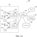
- Figure 1A illustrates an example communication system 100 in which embodiments of the present disclosure could be implemented.
- the system 100 enables multiple wireless or wired elements to communicate data and other content.
- the purpose of the system 100 may be to provide content (voice, data, video, text) via broadcast, narrowcast, user device to user device, etc.
- the system 100 may operate efficiently by sharing resources such as bandwidth.
- the communication system 100 includes a wireless communications network 102 including electronic devices (ED) 110 - 114 and radio access networks (RANs) 120, 122.
- the system 100 also includes a core network 130, a public switched telephone network (PSTN) 132, the Internet 134, and other networks 136.
- PSTN public switched telephone network
- the EDs 110 - 114 are configured to operate, communicate, or both, in the system 100.
- the EDs 110 - 114 are configured to transmit, receive, or both via wireless communication channels.
- Each ED 110 - 114 represents any suitable end user device for wireless operation and may include such devices (or may be referred to) as a user equipment/device (UE), wireless transmit/receive unit (WTRU), mobile station, mobile subscriber unit, cellular telephone, station (STA), machine type communication device (MTC), personal digital assistant (PDA), smartphone, laptop, computer, touchpad, wireless sensor, or consumer electronics device.
- UE user equipment/device
- WTRU wireless transmit/receive unit
- STA station
- MTC machine type communication device
- PDA personal digital assistant
- smartphone laptop, computer, touchpad, wireless sensor, or consumer electronics device.
- the RANs 120 and 122 include base stations 140 and 142, respectively.
- Each base station 140, 142 is configured to wirelessly interface with one or more of the EDs 110 - 114 to enable access to any other base station, the core network 130, the PSTN 132, the Internet 134, and/or the other networks 136.
- the base stations 140 - 142 may include (or be) one or more of several well-known devices, such as a base transceiver station (BTS), a Node-B (NodeB), an evolved NodeB (eNodeB), a Home eNodeB, a gNodeB (sometimes called a "gigabit" NodeB), a transmission point (TP), a transmit/receive point (TRP), a site controller, an access point (AP), or a wireless router.
- Any ED 110 - 114 may be alternatively or jointly configured to interface, access, or communicate with any other base station 140 - 142, the internet 134, the core network 130, the PSTN 132, the other networks 136, or any combination of the preceding.
- the system may include RANs, such as RAN 120, wherein the corresponding base station 140 accesses the core network 130 via the internet 134.
- the EDs 110 - 114 and base stations 140 - 142 are examples of communication equipment that can be configured to implement some or all of the functionality and/or embodiments described herein.
- the base station 140 forms part of the RAN 120, which may include other base stations, base station controller(s) (BSC), radio network controller(s) (RNC), relay nodes, elements, and/or devices.
- BSC base station controller
- RNC radio network controller
- Any base station 140 or 142 may be a single element, as shown, or multiple elements, distributed in the corresponding RAN, or otherwise.
- the base station 140 forms part of the RAN 120, which may include other base stations, elements, and/or devices.
- Each base station 140 - 142 may be configured to operate to transmit and/or receive wireless signals within a particular geographic region or area, sometimes referred to as a coverage area.
- a cell may be further divided into cell sectors, and a base station 140 - 142 may, for example, employ multiple transceivers to provide service to multiple sectors.
- a base station 140 - 142 may be implemented as pico or femto nodes where the radio access technology supports such.
- multiple-input multiple-output (MIMO) technology may be employed having multiple transceivers for each coverage area.
- the number of RAN 120, 122 shown in Figure 1A is exemplary only. Any number of RAN may be contemplated when devising the system 100.
- the base stations 140 - 142 communicate with one or more of the EDs 110 - 114 over one or more air interfaces 150 and 152 using wireless communication links e.g. RF, ⁇ Wave, IR, etc.
- the air interfaces 150 and 152 may utilize any suitable radio access technology.
- the system 100 may implement one or more channel access methods, such as code division multiple access (CDMA), time division multiple access (TDMA), frequency division multiple access (FDMA), orthogonal FDMA (OFDMA), or single-carrier FDMA (SC-FDMA) in the air interfaces 150 and 152.
- CDMA code division multiple access
- TDMA time division multiple access
- FDMA frequency division multiple access
- OFDMA orthogonal FDMA
- SC-FDMA single-carrier FDMA
- the EDs 110 - 114 include EDs that are able to communicate directly with each other via sidelinks 154 and 156.
- a base station 140 - 142 may implement Universal Mobile Telecommunication System (UMTS) Terrestrial Radio Access (UTRA) to establish an air interface 150 using wideband CDMA (WCDMA). In doing so, the base station 140 - 142 may implement protocols such as HSPA, HSPA+ optionally including HSDPA, HSUPA or both. Alternatively, a base station 140 - 142 may establish an air interface 150 with Evolved UTMS Terrestrial Radio Access (E-UTRA) using LTE, LTE-A, and/or LTE-B. It is contemplated that the system 100 may use multiple channel access functionality, including such schemes as described above.
- UMTS Universal Mobile Telecommunication System
- UTRA Universal Mobile Telecommunication System
- WCDMA wideband CDMA
- E-UTRA Evolved UTMS Terrestrial Radio Access
- radio technologies for implementing air interfaces include IEEE 802.11, 802.15, 802.16, CDMA2000, CDMA2000 1X, CDMA2000 EV-DO, IS- 2000, IS -95, IS -856, GSM, EDGE, and GERAN.
- IEEE 802.11, 802.15, 802.16, CDMA2000, CDMA2000 1X, CDMA2000 EV-DO, IS- 2000, IS -95, IS -856, GSM, EDGE, and GERAN Of course, other multiple access schemes and wireless protocols may be utilized.
- the RANs 120 and 122 are in communication with the core network 130 to provide the EDs 110 - 114 with various services such as voice, data, and other services. Understandably, the RANs 120 and 122 and/or the core network 130 may be in direct or indirect communication with one or more other RANs (not shown), which may or may not be directly served by core network 130, and may or may not employ the same radio access technology as RAN 120, RAN 122 or both.
- the core network 130 may also serve as a gateway access between (i) the RANs 120 and 122 or EDs 110 - 114 or both, and (ii) other networks (such as the PSTN 132, the Internet 134, and the other networks 136).
- EDs 110 - 114 may include functionality for communicating with different wireless networks over different wireless links using different wireless technologies and/or protocols.
- PSTN 132 may include circuit switched telephone networks for providing plain old telephone service (POTS).
- POTS plain old telephone service
- Internet 134 may include a network of computers and subnets (intranets) or both, and incorporate protocols, such as IP, TCP, UDP.
- EDs 110 - 114 may be multimode devices capable of operation according to multiple radio access technologies, and incorporate multiple transceivers necessary to support such.
- the RANs 120, 122, base stations 140, 142, and the core network 130 together may be referred to as "network equipment”.
- the network equipment elements may be physically distributed within a coverage area.
- the core network 130 generally includes computer processor hardware that interfaces between the PSTN 132, Internet 134, and other networks 136 and the RANs 120, 122 to provide services to the EDs 110 - 114.
- Figures 1B and 1C illustrate example devices that may be used in implementing the network 102 shown in Figure 1A .
- Figure 1B illustrates an example of an ED 160
- Figure 1C illustrates an example base station 180. These components could be used in the communication system 100 or in any other suitable system.
- the ED 160 includes at least one processing unit 162.
- the processing unit 162 implements various processing operations of the ED 160.
- the processing unit 162 could perform signal coding, data processing, power control, input/output processing, or any other functionality enabling the ED 160 to operate in the communication system 100.
- the processing unit 162 may also be configured to implement some or all of the functionality and/or embodiments described in more detail elsewhere herein.
- Each processing unit 162 includes any suitable processing or computing device configured to perform one or more operations.
- Each processing unit 162 could, for example, include a microprocessor, microcontroller, digital signal processor, field programmable gate array, or application specific integrated circuit.
- the ED 160 also includes at least one transceiver 164.
- the transceiver 164 is configured to modulate data or other content for transmission by at least one antenna or Network Interface Controller (NIC) 166.
- the transceiver 164 is also configured to demodulate data or other content received by the at least one antenna 166.
- Each transceiver 164 includes any suitable structure for generating signals for wireless or wired transmission and/or processing signals received wirelessly or by wire at the antenna 166.
- Each antenna 166 includes any suitable structure for transmitting and/or receiving wireless or wired signals 172.
- One or multiple transceivers 164 could be used in the ED 160.
- One or multiple antennas 166 could be used in the ED 160.
- a transceiver 164 could also be implemented using at least one transmitter and at least one separate receiver.
- the ED 160 further includes one or more input/output devices 168 or interfaces (such as a wired interface to the internet 134 in Figure 1A ).
- the input/output devices 168 permit interaction with a user or other devices in the network.
- Each input/output device 168 includes any suitable structure for providing information to or receiving information from a user, such as a speaker, microphone, keypad, keyboard, display, or touch screen, including network interface communications.
- the ED 160 includes at least one memory 170.
- the memory 170 stores instructions and data used, generated, or collected by the ED 160.
- the memory 170 could store software instructions or modules configured to implement some or all of the functionality and/or embodiments described herein and that are executed by the processing unit(s) 162.
- Each memory 170 includes any suitable volatile and/or non-volatile storage and retrieval device(s). Any suitable type of memory may be used, such as random access memory (RAM), read only memory (ROM), hard disk, optical disc, subscriber identity module (SIM) card, memory stick, secure digital (SD) memory card, and the like.
- the base station 180 includes at least one processing unit 182, at least one transmitter 184, at least one receiver 186, one or more antennas 188, at least one memory 190, and one or more input/output devices or interfaces 192.
- a transceiver not shown, may be used instead of the transmitter 184 and receiver 186.
- a scheduler 194 may be coupled to the processing unit 182. The scheduler 194 may be included within or operated separately from the base station 180.
- the processing unit 182 implements various processing operations of the base station 180, such as signal coding, data processing, power control, input/output processing, or any other functionality.
- the processing unit 182 can also be configured to implement some or all of the functionality and/or embodiments described in more detail herein.
- Each processing unit 182 includes any suitable processing or computing device configured to perform one or more operations.
- Each processing unit 182 could, for example, include a microprocessor, microcontroller, digital signal processor, field programmable gate array, or application specific integrated circuit.
- Each transmitter 184 includes any suitable structure for generating signals for wireless or wired transmission to one or more EDs or other devices.
- Each receiver 186 includes any suitable structure for processing signals received wirelessly or by wire from one or more EDs or other devices. Although shown as separate components, at least one transmitter 184 and at least one receiver 186 could be combined into a transceiver.
- Each antenna 188 includes any suitable structure for transmitting and/or receiving wireless or wired signals 172. Although a common antenna 188 is shown here as being coupled to both the transmitter 184 and the receiver 186, one or more antennas 188 could be coupled to the transmitter(s) 184, and one or more separate antennas 188 could be coupled to the receiver(s) 186.
- Each memory 190 includes any suitable volatile and/or non-volatile storage and retrieval device(s) such as those described above in connection to the ED 160 in Figure 1B .
- the memory 190 stores instructions and data used, generated, or collected by the base station 180.
- the memory 190 could store software instructions or modules configured to implement some or all of the functionality and/or embodiments described herein and that are executed by the processing unit(s) 182.
- Each input/output device 192 permits interaction with a user or other devices in the network.
- Each input/output device 192 includes any suitable structure for providing information to or receiving/providing information from a user, including network interface communications.
- a signal may be transmitted by a transmitting unit or a transmitting module.
- a signal may be received by a receiving unit or a receiving module.
- a signal may be processed by a processing unit or a processing module.
- Other steps may be performed by a machine learning (ML) module.
- the respective units/modules may be implemented using hardware, one or more components or devices that execute software, or a combination thereof.
- one or more of the units/modules may be an integrated circuit, such as field programmable gate arrays (FPGAs) or application-specific integrated circuits (ASICs).
- FPGAs field programmable gate arrays
- ASICs application-specific integrated circuits
- modules are implemented using software for execution by a processor unit for example, they may be retrieved by a processor, in whole or part as needed, individually or together for processing, in single or multiple instances, and that the modules themselves may include instructions for further deployment and instantiation. Additional details regarding the EDs such as the ED 160 and the base stations such as 180 are known to those of skill in the art. As such, these details are omitted here.
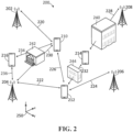
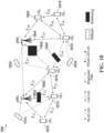
- the wireless communications network 200 includes base stations 202, 204, 206, and 208 configured generally as described above in connection with the base stations 140, 142.
- UEs 210, 212, 214, 216 are in wireless communication with one or more of the base stations 202 - 208.
- the UEs 210, 212, 214, 216 are shown as cellular handset devices but may be any of EDs 110 - 114 shown in Figure 1A and as described above.
- a line-of-sight (LoS) propagation path 220 is associated with transmissions between the base station 204 and the UE 210.
- Another LoS propagation path 222 exists between the base station 204 and the UE 212, and a LoS propagation path 224 exists between the base station 206 and the UE 212.
- a LoS sidelink propagation path 226 also exists between the UE 212 and the UE 210.
- a sidelink connection, transmission, or communication link, is associated with a direct transmission between two UEs that is not routed through one of the base stations 202 - 208.
- a building 240 is located between the base station 208 and the UE 214, and a resulting propagation path 228 is thus a non-line-of-sight (NLoS) path.
- the building 240 acts as a signal shadowing obstruction that attenuates signals propagating through the building.
- Another shadowing obstruction 242 is located between the base station 204 and the UE 210 such that a NLoS propagation path 230 exists between this base station and the UE.
- a sidelink propagation path 232 passes through a shadowing obstruction 244 located between the UE 212 and UE 214.
- the UE 216 has a NLoS sdelink connection 234 with the UE 210 and a LoS connection 236 with the base station 204.
- the obstructions 240, 242, and 244 cause received signal power attenuation and/or fluctuation for a direct propagation path between transmitters and receivers.
- the obstructions 238, 240, and 242 are represented as buildings, but in other embodiments obstructions may be a natural feature such as a hill.
- the buildings 238, 240 would have a fixed location within a geographical coordinate system 250, in other embodiments signal shadowing obstructions may be mobile, such as a large truck or train.
- a process implemented on network equipment for estimating locations of signal shadowing obstructions within the wireless communication network 200 is shown generally at 300.
- the blocks generally represent computer instructions or codes that may be executed to cause various computer processor units making up the network equipment to perform functions for estimating the locations of signal shadowing obstructions.
- Block 302 directs the network equipment of the wireless communications network 200 to receive, from UEs in the network, an identification of neighboring UEs from which the UE receives a reference signal via a non-line-of-sight (NLoS) sidelink transmission.
- the reference signal may be similar to reference signals commonly transmitted between base stations and UEs, which facilitate calculation of UE ranges, channel coefficients, etc.
- the reference signal transmitted by a neighboring UE includes an identification of the UE transmitting the signal, such as an IMSI (International mobile subscriber identity) or other unique identifier associated with the UE.
- the UE identifier may be anonymized for security reasons to prevent the receiving UE from being able to determine identifiers of neighboring UEs. In one embodiment, data ambiguation may be used to anonymize the identifier.
- the base station 204 may thus receive signaling from the UE 216 identifying the UE 210 as having the NLoS sidelink connection 234 with the UE 216.
- the base stations 204 and 206 may each receive respective signaling from the UE 212 identifying the UE 214 as having an NLoS sidelink connection 232 with the UE 212.
- Block 304 of the process 300 then directs the network equipment to estimate locations of signal shadowing obstructions.
- the locations of signal shadowing obstruction are based on UE location estimates 306 for the pair of UEs identified at block 302 as having the NLoS sidelink connection.
- UE location estimates 306 are generated and maintained in a network equipment database for UEs in communication with the network.
- the UE location estimates may be generated based on a variety of different data sets, including uplink or downlink transmissions between the base station and UEs, receiving Global Positioning System (GPS) information from some of the UEs, and/or using other known location information.
- GPS Global Positioning System
- an accurate ground truth location may be established, which acts as an anchor location in the wireless communications network 200.
- the NLoS connection 234 between the UEs 216 and 210 is indicative of a signal shadowing obstruction such as the building 240 being located between the identified pairs of UEs.
- the identification of the NLoS sidelink connection 234 thus facilitates an inference about the location of the obstruction 242 based on the respective locations of the pair of UEs. If the network equipment of the wireless communications network 200 has location estimates for both the UE 210 and the UE 216, then the network equipment may infer that there is an obstruction located in-between the two UEs.
- Block 308 then directs the network equipment to cause the base stations 202 - 206 to configure communications with UEs based on the estimated locations of the signal shadowing obstructions.
- the blocks 302, 304 and 308 may be executed repeatedly to determine locations of signal shadowing obstruction contributions based on the NLoS sidelink connections between multiple pairs of neighboring UEs within the wireless communication network 200. These identified signal shadowing contributions may be combined to generate a shadowing map representing spatial locations of signal shadowing obstructions within the geographical coordinate system 250.
- the shadowing map may be provided to the base stations 202 - 206 to facilitate proactively configuring communication parameters to reduce the frequency of transmission failures.
- the base station 204 in Figure 2 having received the shadowing map, would be able to determine that the building 242 would potentially shadow communications between the base station and the UE 210.
- the base station 204 may thus proactively increase a transmission power when transmitted beams dwell on angular segments that include an obstruction to compensate for signal shadowing.
- conventional wireless communications networks may increase transmission power when signals are shadowed, this increase only occurs reactively after a transmission failure has been encountered. Proactively increasing power would thus potentially avoid the transmission failure and thus reduce transmission delays associated with reactively increasing transmission power.
- the base station 204 may additionally or alternatively proactively select a more robust modulation and coding scheme (MCS) for transmissions to the UE 210 which is known to be located behind the building 242.
- MCS modulation and coding scheme
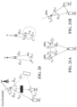
- a base station 400 may be operably configured to selectively avoid directing a transmission beam in a direction of a signal shadowing obstruction 402 as shown in Figure 4A .
- a UE 404 may be left to be serviced by another base station (not shown). If locations of UEs in a network are known, the base station 400 may also cause beams to dwell in angular segments that are known to include UEs while avoiding spending time dwelling in angular segments that do not currently include any UEs.
- a base station 410 may initiate handoff of a shadowed UE 412 to another base station 414, for which signal transmissions are not affected by the signal shadowing obstruction 402. Additionally, knowledge of locations of the signal shadowing obstruction 402 may facilitate reuse of the same non-orthogonal spectrum being used by the other base station for signal transmissions to a shadowed UE 412 when it is known that the obstruction should reduce interference between respective signal transmissions from the two base stations 410 and 414.
- the base stations 202 - 208 would generally also receive reference signals from the UEs 210 - 216 as part of uplink transmissions from the UEs to the base stations.
- the base stations 202 - 208 on receiving the reference signals may make a determination that the reference signal transmitted was received via a NLoS propagation path.
- a UE may make a determination that a reference signal transmitted by a base station was received via a NLoS propagation path.
- the identifications of NLoS downlink and uplink transmissions may advantageously be combined with the identification of NLoS sidelink transmissions between neighboring UEs for generating the shadowing map.
- One advantage of including uplink and downlink transmissions is that the location of the base stations 202 - 208 may be accurately established. Anchor locations when used in the generation of shadowing locations may improve the spatial accuracy of the resulting shadowing map.
- a method for directing a UE or base station to perform the NLoS transmission determination implemented on one of the UEs is shown generally at 320.
- the UE 216 will previously have received LoS/NLoS prediction parameters 322 from the network equipment (i.e. via the base station 204).
- the LoS/NLoS prediction parameters 322 are periodically provided by the network equipment to UEs and are used to implement a LoS/NLoS prediction model on the UE 216.
- Block 324 directs the UE 216 to use the model to infer whether a received sidelink communication from the neighboring UE 210 was received via an NLoS propagation path.
- block 326 transmits the anonymized UE identifier of the neighboring UE 210 to the base station 204. If the sidelink communication is determined to be a LoS communication, no identification is required to be transmitted to the base station 204 for establishing the shadowing obstruction locations. However, the LoS identification may be used for generating UE location estimates as described below and may still be transmitted to the base station 204. In the US 16 /675597 application, UE location estimates are further generated based on the receiving range estimates for line-of-sight (LoS) sidelink transmissions between pairs of UEs. These UE location estimates may be used as a source of the UE location estimates shown at 306 in Figure 3 .
- LoS line-of-sight
- the system 500 includes a LoS/NLoS prediction module 502 on each of the UEs 210 - 216 shown in Figure 2 .
- the LoS/NLoS prediction module 502 implements the LoS/NLoS identification model using the LoS/NLoS prediction parameters 322 that are provided to UEs by the network equipment as described later herein.
- the UEs and base stations in the network and communication links between these elements are depicted at 510, which shows both LoS and NLoS connections.
- the signal shadowing obstructions are represented at 510 by rectangular blocks.
- the UEs and base stations may be represented as a set of nodes in a network graph with connections between the nodes v being depicted at 510.
- the LoS/NLoS prediction module 502 executes the blocks 302 - 308 shown in Figure 3A and generates inference pairs N LoS v N NLoS v .
- Each inference pair includes a set of inferences N LoS v that identify UEs and/or base stations v' with which a UE v has a LoS connection and a set of inferences N NLoS v that identify UEs and/or base stations v' with which the UE v has an NLoS connection.
- the NLoS connections are represented at 512 using broken lines and the LoS connections are represented using solid lines.
- N NLoS ⁇ UE v represents a set of identifications of nodes v having NLoS sidelink connections with UEs v'
- N NLoS ⁇ BS v represents a set of identifications of nodes v having NLoS downlink connections with base stations v'
- N NLoS v is the union of the sets N NLoS ⁇ UE v and N NLoS ⁇ BS v .
- the LoS/NLoS prediction module 502 in this embodiment also generates LoS identifications for the uplink, downlink, and sidelink connections, and transmits signaling identifying these connections back to the network equipment.
- the network equipment includes a localization system 504, which
- the UE location estimates may be otherwise generated without the use of LoS sidelink connection information.
- the network equipment portion of the system 500 also includes a shadowing map generator 506, which receives the UE location estimates 306 from the localization system 504.
- the shadowing map generator 506 also receives the sets of NLoS identifications in equation 1 and combines the UE location estimates 306 and the NLoS identifications.
- the set of nodes N LoS v is thus provided to the localization system 504 to estimate locations z v of the nodes v , which in turn is provided to the shadowing map generator 506. It is not necessary to establish location estimates for all of the UE nodes in the network 200.
- the graph V" is depicted at 514 in Figure 5 and is updated iteratively as additional inference pairs N LoS v N NLoS v are received and edges and vertices are added.
- the shadowing map generator 506 applies kernel density estimation (KDE) to the graph G" by updating the following shadowing map function:
- KDE kernel density estimation
- K z ⁇ v , v ′ l ⁇ v , v ′ l is a kernel density function that is centered at a location ⁇ v , v ′ l ⁇ R 2 for each (v,v') link edge in the graph and where ⁇ v , v ′ l ⁇ R 2 ⁇ 2 is the covariance matrix for that link.
- Equation 4 also includes a time-dependent factor ⁇ l ⁇ [0,1], which together with the time-span term T implements a discounting factor.
- the time-dependent factor ⁇ l causes more recently received identifications of neighboring UEs to be assigned a greater weight than previously received identifications of neighboring UEs.
- the discounting factor ⁇ l ensures that the model remains agile and adaptive in a wireless communications network 200 where shadowing obstructions may themselves be mobile.
- Each edge or NLoS link in the graph G" thus includes the estimated locations z v of the nodes at its two ends.
- the signal shadowing obstruction associated with the NLoS communication link between nodes (v, v') is thus assumed to be centered at a location ⁇ v , v ′ l halfway between the two nodes v.
- the extent of the shadowing obstruction along the direct path and in the direction of the vector v v is defined by ⁇ v,v' , which may be based on an estimated path loss for the signal transmission.
- Eigenvalue decomposition using eigenvalues ⁇ that are proportional to a shadow fading coefficient, is used to generate the covariance matrix ⁇ v , v ′ l .
- a larger shadow fading coefficient is most likely associated with a larger shadowing obstruction, and results in a wider kernel being used in equation 4 when evaluating shadowing contributions associated with identified NLoS communication links.
- the shadow fading coefficient ⁇ ( z ) may be available as a function of location throughout the network based on extensive experimentation.
- the communication parameters p v t , g v' , and p v ′ r are commonly available within the wireless communications network 200 as these parameters are monitored by UEs and base stations and may be routinely collected by the network equipment. In other embodiments, measures of shadow fading other than equation 7 may be used.
- the estimated shadow fading coefficient ⁇ v,v' is then used in equation 6 to determine the covariance matrix ⁇ v , v ′ l .
- the covariance matrix is in turn used in equation 4 to generate probable locations 518 for the signal shadowing obstruction within the geographical coordinate system 250.
- K z ⁇ v , v ′ l ⁇ v , v ′ l in equation 4 may be made based on the level of detail desired for the shadowing map.
- the wings of the above Gaussian kernel extend from - ⁇ to ⁇ and the kernel has smooth transitions, leading to a shadowing map function ( z , t ) that is generally free of spurious fluctuations and sudden jumps.
- a shadowing map function ( z , t ) that is generally free of spurious fluctuations and sudden jumps.
- smaller shadowing obstructions may be buried under the wings of larger obstructions.
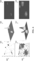
- simulated results for generation of a shadowing map are shown at 600 and 602.
- the graph 604 on the left shows a 2D view of five shadowing objects represented as block within a network environment at a time when only a few NLoS communication links surround three of the obstructions.
- the center graph 606 shows a 3D graphical depiction of the estimated shadowing obstruction locations determined by KDE estimation for the scenario shown in the graph 604.
- the graph 608 on the right is a 2D slice taken horizontally through the graph 606 at a height dependent on the desired resolution. Horizontal slices taken at different heights will yield different extents for the estimates of signal shadowing obstruction locations.
- the second set of graphs 610 - 614 are taken at a later time when a larger number of UEs and thus NLoS communication links surround each of the obstructions.
- obstructions are intercepted by a larger number of communication links, improving the resolution of the shadow map function ( z , t ).
- one or both of the UEs associated with any identified NLoS sidelink communication may be in motion, and would thus have a UE location that changes with time. In this case the UE and its neighboring UE or base station would be able to provide successive NLoS identifications for estimating locations of signal shadowing obstructions, further improving the resolution of the KDE spectrum ( z, t ) .
- Each communication link between the set of nodes in the wireless communications network 200 thus provides a shadowing contribution which are combined using the function ( z, t ) in equation 4 to generate an overall map of signal shadowing locations.
- Combining shadowing contributions in a network having a large number of UEs and thus a large number of identified NLoS communication links results in a more representative shadowing map.
- the accuracy of shadowing map may also depend on factors other than the concentration of NLoS communication links identified for each obstruction. Inaccuracies caused by the LoS/NLoS prediction module 502 may cause a LoS link to be inferred as a NLoS link or vice versa. Inaccuracies in the UE location estimates 306 may cause the location of nodes to be displaced from their actual locations, thus also displacing the center location ⁇ v , v ′ l assumed for the shadowing obstruction. The probability of misdetection would generally have a negligible effect of creating a small bias in the resulting signal shadowing map.
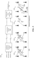
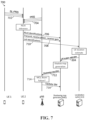
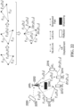
- a signal flow diagram illustrating signaling between nodes for generation of the shadowing map by the shadowing map generator 506 in accordance with one disclosed embodiment is shown generally at 700.
- the signaling involves two UEs, including UE1 and UE2, and network equipment.
- the network equipment includes a gNodeB (gNB) base station, the localization system (LS) 504, and the shadowing map generator (SMG) 506.
- the signal flow diagram 700 illustrates signaling between UE1 and UE2, and signaling between UE2 and the network equipment.
- the signal flow diagram 700 also illustrates signaling between the gNB, LS, and SMG on the network equipment side.
- the UE1 transmits a sidelink positioning reference signal (SL-PRS) 702 to the UE2 including the anonymized identifier of the UE1.
- the gNB also transmits a positioning reference signal (PRS) 704, which is received at the UE2.
- PRS positioning reference signal
- Each of the signals 702 and 704 are processed by the LoS/NLoS prediction module (502 in Figure 5 ) on UE2 to generate NLoS inferences for the received reference signals.
- the SL-PRS 702 is determined to be received via an NLoS propagation path, the UE2 generates signaling 706 to transmit the NLoS identification including the UE1 anonymized identifier, via the gNB, to the SMG.
- the UE2 further transmits signaling 708 including information derived from the received reference signals such as transmit power, received power, and receiver gain that facilitate determination of signal shadow fading coefficients for estimating the extent of shadowing contributions associated with the signals 702 and 704.
- LoS sidelink information is used for generating UE location estimates
- the UE2 transmits signaling 710 including respective identifications for the UE1 and/or gNB to the location system (LS).
- the UE2 would also need to determine range estimate information for the reference signals 702 and 704.
- the range estimates are transmitted to the LS via the gNB to enable the use of the LoS sidelink information in generating the UE location estimates.
- the signaling 710 may be omitted.
- the LS implements the localization system 504 shown in Figure 5 , which receives the LoS identifications and range estimates and generates UE location estimates 306 as described earlier herein.
- the UE location estimates 306 are provided to the SMG, which uses the estimates along with the received NLoS identification signaling 706 and transmit power, received power, and receiver gain signaling 708 as inputs for the shadowing map generator 506 shown in Figure 5 .
- the SMG generates the shadowing map and transmits shadowing map data 712 to the gNB and to other gNBs in the network for use in configuring communications with UEs in the wireless communications network 200.
- Additional signaling not depicted in Figure 7 may be required from the network equipment, such as assigning and reporting an anonymized and unique identifier to each UE.
- the list of anonymized UE identifiers enables a UE to identify neighboring UEs from which it receives the SL-PRS in order to report NLoS communication links back to the network equipment.
- the gNB implements ongoing channel estimation and continually monitors for beam failure and/or increased bit error rates (BER) for transmissions.
- the gNB implements a beam failure monitoring function 714, which monitors unsuccessful attempts to adapt the modulation and coding scheme (MCS) or the incidence of high BER for transmissions by the gNB.
- MCS modulation and coding scheme
- An increasing level of transmission failures may indicate that the signal shadowing map has become outdated.
- the beam failure monitoring function 714 may produce a signal 716 that initiates an update of the shadowing map by the SMG.
- the shadowing map generator 506 responds to receiving the signal 716 from the gNB of such transmission failures by generating updated shadowing map data 712, which is provided to the gNB and other gNBs in the wireless communications network 200.
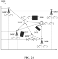
- the wireless communications network 800 includes a base station 802 and UEs 810, 812, and 814. Buildings 820 and 822 within the wireless communications network 800 act as signal reflectors. A signal transmitted from the base station 802 to the UE 810 is reflected by the building 820, resulting in an indirect propagation path 830.
- a signal transmitted from the UE 810 to the UE 812 is reflected by a portion of the building 822, resulting in an indirect propagation path 832; and a signal transmitted from the UE 814 to the UE 810 is reflected by a portion of the building 822, resulting in an indirect propagation path 834.
- the base station 802 forms part of network equipment implementing the wireless communications network 800, as described in more detail later herein.
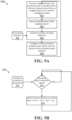
- FIG. 9A a process implemented on network equipment for estimating locations of signal reflectors within the wireless communication network 800 is shown generally at 900.
- the blocks generally represent computer instructions or codes that may be executed to cause various computer processor units making up the network equipment to perform functions for estimating the locations of signal reflectors.
- Block 902 directs the network equipment of the wireless communications network 800 to receive, from UEs in the network 200, sidelink transmission information including range estimates indicative of a range associated with a reference signal received from a neighboring UE via the sidelink transmission over indirect propagation paths.
- the UEs 812 and 814 each transmit reference signals via indirect propagation paths 832 and 834 respectively, and the UE 810 receives and processes these signals to extract range estimates.
- the range estimates are transmitted by the UE 810 via the base station 802 to the network equipment.
- the UE 810 also generates a received power measurement for each reference signal and transmits the received power via the base station 802 to the network equipment.
- Block 904 directs the network equipment to receive an identification of the neighbouring UEs (812 and 814) as anonymized identifiers transmitted by the UE 810, generally as described above in connection with the signal shadowing embodiment.
- Block 906 of the process 900 then directs the network equipment to estimate locations of signal reflectors within a geographical coordinate system 850.
- the network equipment uses the UE location estimates 306 for the UEs 810 - 814, the received range estimates, and the received power to generate signal reflector location estimates.
- Block 908 then directs the network equipment to cause the base station 802 to configure communications with UEs based on the estimated locations of the signal shadowing obstructionsBlocks 902 - 908 may be executed continuously to determine locations of signal reflector contributions within the wireless communications network 800. These identified signal reflector contributions may be combined to generate a reflector map representing spatial locations of signal reflectors within the geographical coordinate system 850. The reflector map may be provided to the base stations 202 - 208 to facilitate proactively configuring communication parameters to reduce the frequency of transmission failures.
- the reflector map for the wireless communications network 800 may be used to significantly increase a capacity of the network by facilitating proactive beamforming. If the network equipment has knowledge of locations of reflectors that can act to reflect and re-direct transmission beams, the base station can be directed to select a particular beam that points in the direction of a reflector in order to increase signal to noise ratio and reduce interference. As shown in Figure 10A , if a UE 1000 would experience weak reception of signals from a base station 1002, the base station may proactively direct a transmission beam 1004 toward a known signal reflector 1006 to cause the beam to be redirected by the signal reflector to the UE. In this example, a direct propagation path between the base station 1002 and the UE 1000 is shadowed by an obstruction 1008.
- UEs 1012 - 1016 are located within an area served by a transmission beam 1018 from a base station 1010, which may cause interference at the UEs.
- transmissions intended for the UE 1012 may interfere with other transmissions directed to the UEs 1014 and 1016 from other base stations.
- the network equipment may be configured to detect this situation and respond by proactively directing a beam 1020 toward a signal reflector 1022 to cause the beam to be redirected by the signal reflector to the UE 1012 such that the potential interference to UEs 1014 and 10916 is reduced or eliminated.
- the network equipment may make a determination that a very strong LoS communication beam 1030 directed toward a UE 1028 from a base station 1026 is causing a reduction in MIMO channel matrix rank.
- the rank of the MIMO channel matrix is an indicator of how many data streams can be spatially multiplexed on the MIMO channel.
- the base station in Figure 10D may respond by proactively directing one or more additional transmission beams 1032 and 1036 toward signal reflectors 1034 and 1038 that cause the additional beams to be redirected to the receiving UE.
- the transmission from the base station to the UE may then be multiplexed over the direct beam 1030 and the additional beams 1032 and 1036 to improve a MIMO matrix rank for the signal transmission.
- a method implemented on the UE 810 for generating the NLoS range estimates received at block 902 of the user equipment implemented process 900 is shown generally at 920.
- the UE 216 will previously have received parameters 322 for configuring a LoS/NLoS identification model from the network equipment (e.g. via the base station 802).
- Block 324 directs the UE 810 to use the model to infer whether a received sidelink reference signal from the neighboring UE 210 was received via an NLoS propagation path (i.e. an indirect propagation path). If this is the case, block 326 directs the network equipment to process the reference signal to determine range estimates for the indirect propagation path.
- the range estimates are then transmitted to the network equipment via the base station 802 along with an identification of the UE from which the communication was received. If the sidelink communication is determined to be a LoS communication, no range estimates are generated for this purpose.
- the base station 802 would generally also receive reference signals from the UEs in the network as part of uplink transmissions from the UEs to the base stations.
- the base station 802 on receiving the reference signals, may make a determination that the reference signal transmitted was received via an indirect propagation path as described above.
- a UE may make a determination that a reference signal transmitted by a base station was received via an indirect propagation path.
- the range estimates for indirect uplink and downlink propagation paths may advantageously be combined with the identification of indirect sidelink transmissions between neighboring UEs for generating the reflector map.
- One advantage of including uplink and downlink transmissions is that the location of the base station 802 provides an anchor location, which may improve the spatial accuracy of the resulting shadowing map.
- a block diagram of a system for generating a reflector map is shown generally at 1100 in which the UEs implement a channel estimation function 1102.
- the channel estimation function 1102 receives reference signals via uplink, downlink, and sidelink transmissions and determines signal propagation parameters for the received reference signal.
- An example of a received PDP reference signal is shown at 1120 in the form of a power delay profile (PDP).
- PDP plots an intensity of a reference signal received via a multipath channel as a function of time delay (i.e. the difference in travel time between multipath signal arrivals).
- reference signals may be received via a direct propagation path or via an indirect propagation path after one or more reflections at signal reflection obstructions in the network.
- the PDP has a first power peak P 1 , which would correspond to a reference signal received directly via a LoS propagation path.
- Second, third, and fourth power peaks P 2 , P 3 and P 4 correspond to reference signals received indirectly after one or more reflections at reflecting surfaces within the network environment.
- the channel estimation function 1102 determines distances ⁇ corresponding to the power peaks P 1 , P 2 , P 3 and P 4 (i.e. distance ⁇ 1 for the direct propagation path, and distances ⁇ 2 ⁇ ⁇ N mp for the indirect propagation paths.
- Indirect propagation paths that involve multiple signal reflectors, and thus more than one signal reflection, are removed from consideration by applying a minimum power threshold ⁇ . Accordingly, only single-reflection indirect propagation paths are considered, which reduces complexity. Indirect signal propagation paths ( ⁇ 3 , ⁇ 4 %) that involve multiple reflections will generally be weaker than signals that only undergo a single reflection ( ⁇ 2 ).
- PDP power delay profile
- the power threshold ⁇ is selected such that the set of distances ⁇ ⁇ T v , v ′ Indirect are constrained to distances traversed by N mp ′ for single-reflection propagation paths between the UEs.
- the propagation distance and power sets T v , v ′ Indirect and P v , v ′ Indirect are transmitted by UEs in the wireless communications network 800 via the base station (802 in Figure 8 ) to a reflector map generator 1104, which forms part of the network equipment.
- the UE performs the thresholding function and only transmits distances ⁇ ⁇ T v , v ′ Indirect for single reflection paths.
- all distances ⁇ ⁇ T v , v ′ Indirect may be transmitted by the UE to the base station, which may perform the thresholding function.
- the system 1100 also includes the LoS/NLoS prediction module 502, which implements the LoS/NLoS prediction model generated and trained by the network equipment for determining whether communication links with other UEs or base stations are via LoS or NLoS propagation paths.
- the system 1100 also includes the localization system 504 which receives the LoS identifications from the LoS/NLoS prediction modules 502 associated with the nodes v .
- the localization system 504 uses these identifications in establishing UE location estimates z v for the nodes v , which are provided to the reflector map generator 1104.
- the distance ⁇ 1 associated with the indirect propagation path 832 establishes that the signal reflector 822 is located somewhere on the locus of a 3D ellipsoid surface having a focal distance d and whose foci coincide with the locations of the UE 812 and UE 810.
- the 3D ellipsoid surface is shown in Figure 8 represented by a 2D ellipse 840 for sake of illustration.
- the ellipse 840 thus represents possible locations of the reflector 822, but it remains uncertain as to where on the ellipsoid surface the reflector is actually located.
- the uncertainty about the location of the reflector is reduced to facilitate producing an estimate of the location of the reflector.
- the sidelink between the UE 814 and the UE 810 establishes another ellipsoid surface locus 842, which reduces the uncertainty of the reflector location at the building 822 to an uncertainty cloud 846 located at the intersections between the ellipsoid surfaces 840 and 842.
- the link between the UE 814 and the base station 802 establishes another ellipsoid surface locus 844, which reduces the uncertainty of the reflector location at the building 820 to an uncertainty cloud 844.
- locations of significant reflecting obstructions within the geographical coordinate system 850 may be estimated. Further observations based on sidelinks between the UEs and uplinks/downlinks between UEs and the base station would further reduce the size of the uncertainty clouds 844 and 846.
- the problem can be simplified such that the reflector contribution corresponding to each ⁇ ⁇ T v , v ′ Indirect is located on an ellipse of focal length d at which the foci of the UE 812 and UE 810 are located.
- the locations may be taken from the UE location estimates 306 generated by the localization system 504. Alternatively, in some cases locations may be available as ground-truth locations for nodes such as a base station. Practically, even where a ground-truth location z 1 ⁇ z 2 ⁇ is available, equation 12 is not satisfied due to several reasons:
- the clock skew and bias cause an unknown circular shift in the power delay profile (PDP) for a channel between nodes v and v' . It may be assumed that each node in the network has an independent clock generator, which means that the PDP for links between nodes in the network would be subjected to an independent time shift. The assumption that the shifts are independent might not be made in cases where the network implements a clock synchronization protocol.
- T v , v ′ Indirect and P v , v ′ Indirect are the propagation distance and power sets defined in equations 10 and 11 that are associated with an edge (v, v') of G" .
- the base stations are able to make observations of T v , v ′ Indirect and P v , v ′ Indirect for communications received at the base station from a UE, for sidelink communications between UEs this information cannot directly or indirectly be inferred by the base station as such. The observations thus need to be transmitted from UEs to the base station.
- the transmitted sets T v , v ′ Indirect and P v , v ′ Indirect may include information for all resolved indirect-path signal components. Additionally, because the required UE location estimates 306 may be based in part on LoS sidelink connections between neighboring UEs, sets T v , v ′ Direct / Indirect , P v , v ′ Direct / Indirect including all direct and indirect signal components may be transmitted by UEs. If any of the UEs are moving within the wireless communications network 800, successive sets T v , v ′ Direct / Indirect , P v , v ′ Direct / Indirect may be transmitted, thus providing temporal data in addition to the spatial data.
- the reflector map generator 1104 implements a kernel density estimation (KDE) algorithm on the graph G" to generate the reflection map by updating the following metric:
- P z ⁇ ⁇ n mp v , v ′ , z v , z v ′ , 1 / p n mp v , v ′ from equation 16 or 17 acts as the kernel density function for producing the reflector map represented as an oval at 1116 in Figure 11 .
- time-dependent factor ⁇ l ⁇ [0,1] and time-span term T implement a discounting factor such that when periodically updating the reflector map in response to receiving ongoing observation sets T v , v ′ Indirect , P v , v ′ Indirect , more recently received observations are assigned a greater weight than previously received observations. This helps to keep the model agile and adaptive in wireless environments where the obstructions that reflect signals may be mobile.
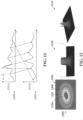
- simulated results for generation of a reflector map are shown at 1300.
- the graph 1302 on the left depicts the nodes v and v' as dots with the ellipsoid 1304 representing the strongest indirect propagation path between the nodes, the ellipsoid 1306 representing the 2 nd strongest indirect propagation path, and the ellipsoid 1308 representing the 3 rd strongest indirect propagation path.
- the reflector map ( z , t ) at 1310 has the appearance of a ring probability density function, and is centered at ( z v + z v' )/2 , and has spreading ⁇ n mp v , v ′ .
- the spreading ⁇ n mp v , v ′ is selected to be inversely proportional to the magnitude of received power for n mp th power at a graph edge ( v , v ' ) .
- the reflector map ( z , t ) at 1312 has been updated to include additional indirect link inferences and the locational posterior yields a PDF with lower uncertainty.
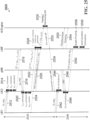
- the signaling involves two UEs, including UE1 and UE2, and network equipment.
- the network equipment includes a gNodeB (gNB) base station, the localization system (LS) 504, and the reflector map generator (RMG) 1104.
- the signal flow diagram 1400 illustrates signaling between UE1 and UE2, and signaling between UE2 and the network equipment.
- the signal flow diagram 1400 also illustrates signaling between the gNB, LS, and RMG on the network equipment side.
- the RMG may be implemented on a processor unit in communication with a processor-readable memory that stores processor-executable instructions that cause the processor to perform the functions disclosed above.
- the UE1 transmits a sidelink positioning reference signal 1402 including the anonymized identifier (SL-PRS) of the UE1 to the UE2.
- the gNB also transmits a positioning reference signal (PRS) 1404, which is received at the UE2.
- PRS positioning reference signal
- Each of the signals 1402 and 1404 are processed by the LoS/NLoS prediction module 502, and if determined to be received via a LoS propagation path, the UE2 transmits signaling 1406 including respective identifications for the UE1 and/or gNB to the LS for generating UE location estimates.
- the UE2 also determines range estimate information for the reference signals 1402 and 1404 for transmission to the RMG.
- the LS receives the LoS identifications and range estimates and generates UE location estimates 306 as described earlier herein. Alternatively, where the UE location estimates are otherwise determined, the signaling 1406 may be omitted.
- the channel estimation function 1102 on the UE2 further processes the SL-PRS and PRS signals 1402 and 1404 to generate signaling 1408 including propagation distance and power sets T v , v ′ Indirect and P v , v ′ Indirect as described above. Because the reflection map construction algorithm works by associating indirect propagation path delays with estimated UE locations for nodes (v, v') associated with the link, the signaling 1408 is accompanied with anonymized IDs of the neighboring UEs to enable determination of the locations of the nodes, as described above in connection with the shadowing map generation.
- the RMG generates reflector map data 1410 as described above and transmits the data to the gNB and other gNBs in the network for use in configuring communications with UEs.
- the gNB implements the beam failure monitoring function 714 as described above in connection with the shadowing map generation embodiment. Beam failures for signal transmissions within the gNB cell cause the beam failure monitoring function 714 to produce a signal 1412 that causes the RMG to update the reflector map.
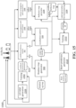
- FIG. 15 a block diagram showing a pipeline of information flows between modules making up the network equipment in the networks 200 and 800 is shown generally at 1500.
- the pipeline 1500 incorporates elements described above in connection with the shadowing map generation system 500, the reflector map generation system 1100, and additional elements involved in a implementing these functions in the network.
- the LoS/NLoS prediction module 502 is implemented on each base station and UE node.
- the LoS/NLoS prediction module 502 processes reference signals received at the node and is configured for operation by receiving LOS/NLOS prediction parameters 322.
- the parameters 322 are generated by a training module 1502, which is implemented on the network equipment.
- the training module 1502 receives labeled LoS training data generated by a LoS label generation module 1504, which processes uplink, downlink and sidelink communications.
- the parameters 322 may be continuously generated by the LoS label generation module 1504 and training module 1502, and are periodically communicated to base stations and UEs to update the LoS/NLoS prediction module 502 for current network conditions.
- the LoS/NLoS prediction module 502 thus processes reference signals received at each base station and UE and identifies the received signals as having been received via either a LoS or an NLoS propagation path.
- a direct propagation path identification module 1506 estimates the range parameters of the direct propagation path.
- the selected direct path range estimates are then fed by to the localization system 504.
- the localization system 504 estimates the UE locations in a collaborative (parallel) or non-collaborative (sequential) manner.
- the generation of accurate and unbiased UE location estimates by the localization system 504 is effective in reducing spatial location errors. Spatial location errors would propagate through the pipeline 1500 and manifest in the shadowing and reflection data produced. Reducing the incidence of UE location estimates being determined based at least in part on indirect NLoS communications reduces location bias in the reflector map.
- the shadowing map generator 506 generates the shadowing map based on NLoS identifications and location estimates provided by the localization system 504, as described above in detail.
- the shadowing map generator 506 produces shadowing map data, which is provided to the communication subsystems of the base stations for use in configuring communications with UEs.
- an indirect propagation path identification module 1508 estimates range parameters for 2 nd or subsequent indirect path distances between nodes.
- the indirect path range estimates are fed to the reflector map generator 1104. As disclosed above, only indirect propagation paths that undergo a single reflection may be selected and range estimates for multiple reflection paths may be discarded by the module 1508.
- the reflector map generator 1104 receives the location estimates from the localization system 504 and the indirect range estimates from the module 1508 and generates the reflector map including locations of signal reflectors.
- the reflector map on its own does not provide information as to which signal reflectors could be of use in communications between base stations and UEs.
- the pipeline 1500 further includes a beam prediction generator module 1510, which is implemented to facilitate location aware beam steering by the base station.
- a beam prediction generator module 1510 which is implemented to facilitate location aware beam steering by the base station.
- the beam prediction generator module 1510 operates on the reflector map data 1410 that includes locations z v , v ′ refl ⁇ R 2 of possible reflectors that could be used by a base station station v to redirect a transmission beam to a UE v' .
- the beam predictor 1510 also receives location estimates z v , z v ′ ⁇ R 2 for the base station station v and the UE v' .
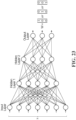
- a set of labelled training data z v , v ′ refl are generated for locations z v , z v' using the reflector map L(z, t) of equation 20 by:
- the training set is used in a training exercise to determine the weights w i for the neural network 1600 to generate a mapping from the transmitter to receiver locations via an effective reflector.
- the use of the trained neural network 1600 produces a mapping that can generalize to unseen reflector examples and also may alleviate the consequences of training using noisy labels.
- the neural network 1600 has a low dimensional input layer 1604 and output layer 1606, the width and depth of the neural network is relatively modest but should have sufficient layer depth to generalize well.
- the neural network 1600 is shown as fully connected with hidden layers 1610 sized to gradually increase and then decrease. Alternatively , the neural network 1600 may be differently configured.
- the neural network configuration and the trained weights w i may be subsequently passed to the base stations, where the trained network is used as a model for making proactive beam steering decisions.
- a ray propagating along NLoS path 1724 may be stronger than the ray propagating along the weak LoS path 1728 and therefore it is not possible to distinguish these LoS and NLoS rays from each other at the UE 1708 based only on received signal power.
- LoS identification may still be an attractive option for positioning determination.
- techniques based on using only LoS links for positioning determination are often referred to as LoS identification techniques, it should be noted that LoS identification according to embodiments disclosed herein may involve identifying LoS links, identifying NLoS links, and/or otherwise distinguishing LoS links and NLoS links from each other. Regardless of the type(s) of links that are actually identified, determining which links are NLoS links and removing them from positioning determination is an important step in improving the accuracy of positioning or localization systems based on LoS identification.
- SL communication refers to the ability of close-by UEs to communicate or cooperate with each other directly, rather than through network communications.
- An SL is therefore an example of a direct wireless communication link between UEs.
- MIMO Multiple Input Multiple Output
- Shadowing can potentially be detected if UEs can be become "positioning proxies" for each other.
- the probability of LoS in SL communications is expected to be higher than in uplink (UL) or downlink (DL) communications, because UE cooperation through SL communications is expected to be allowed only within limited geographical areas to conserve UE power and keep SL interference patterns in a communication network under control.
- Some embodiments disclosed herein relate to building or training a model that predicts the presence of NLoS links using Machine Learning (ML), and illustratively Neural Networks (NNs).
- ML Machine Learning
- Ns illustratively Neural Networks
- UL, DL, and SL communications and measurements are used in some embodiments in collecting data for building or training such a model.
- the present disclosure encompasses embodiments in which existing communication network infrastructure, rather than an expensive and non-autonomous expert system, is exploited to generate training datasets at a much larger scale and possibly in an uninterrupted manner instead of relying on availability of potentially less noisy but much smaller datasets obtainable from expert systems.
- PDFs Probability Distribution Functions
- One possible approach to help mitigate or remedy drift and associated prediction error would be to morph or integrate an exploration subsystem, which is involved in label collection and training, into an exploitation subsystem, which utilizes a trained model.
- an exploration subsystem which is involved in label collection and training
- an exploitation subsystem which utilizes a trained model.
- one such approach may rely on "crowdsourcing" abilities of communication networks to collect a large amount of data during normal communications. This in effect leverages the distributed and mobile nature of UEs in order to collect large datasets for training.
- Existing infrastructure, rather than expensive and non-autonomous expert systems can then be used to generate data for training but at a much larger scale and in an uninterrupted manner instead of relying on availability of smaller amounts of labelled data from expert systems.
- the present disclosure relates in part to a model for predicting the presence of LoS/NLoS links based on range estimates that were collected or otherwise determined from UL, DL, and SL communications, in a cost-effective and adaptive manner.
- Other information such as angle estimations based on UL communications, may also be used in building or training such a model.
- training data for developing a model includes a collection of tuples ⁇ ( x, w ) l ⁇ l , where x is a feature of l th link that is spatially unique but can be replicated temporally, and w indicates whether the l th link is NLoS, LoS, or unknown.
- RSs Reference Signals
- the example wireless communication network 1800 includes BSs 1802, 1804, each shown by way of example as a gNodeB (gNB), and UEs 1810, 1812, 1814, 1816, 1818, 1820.
- the operating environment of the UEs includes obstacles in the form of reflectors 1830, 1832, 1834 and shadowing obstacles 1840, 1842, 1844.
- Unobstructed LoS links are shown as solid lines, and different dashed line types are used in Figure 18 to illustrate NLoS links and LoS links that are affected by shadowing.
- N BS v ⁇ N v denoting the set of BSs that (i) are connected with UE v and (ii) were subject to DL range measurements with UE v
- T v DL x v , v ′ ⁇ ⁇ v , v ′ : v ′ ⁇ N BS v , v ⁇ V
- is the DL range estimate between BS v' and UE v and x v,v' is a channel tensor as described above.
- a full connectivity graph may also take into account T v UL , the information set inferred by each BS as a result of UL ranging.
- Each BS like each UE, may transmit signaling that is indicative of this set to a network component that generates the connectivity graph, if the connectivity graph is not generated by the BS itself.
- a full-connectivity graph can be established and NLoS/LoS labels for the tensors x v,v' can be generated as disclosed by way of example in further detail elsewhere herein. These labels and tensors are subsequently used in training, which is also disclosed herein by way of example.
- Range estimate expiration relates to environment changes, due to UE mobility for example, as a result of which distances between UEs and other elements in a communication network vary in time. Without any blockage or shadowing in a communication network, all links are LoS links.
- Figure 19 includes block diagrams illustrating examples of connectivity circles.
- the examples (b) and (d) in Figure 19 are applicable to the UE positions as shown in Figure 18 , and the examples (a) and (c) relate to different UE positions than those shown in Figure 18 .
- Other connectivity circles are present in example shown in Figure 18 , and it should also be noted that others may dynamically appear and disappear as UEs move.
- equation 27 specifies that the range for any edge in a closed connectivity path should be smaller than the sum of ranges for the other edges in that same closed connectivity path.
- equation 27 is the triangle inequality.
- an exhaustive search through a full-connectivity graph G may be performed, to find a minimum distance circle between every two nodes v, v' where is the set of circles in the graph and r v , v ′ ⁇ is an index of a circle that achieves the minimum sum delay d e ⁇ based on ranges or range estimates associated with the edges that form a circle including v, v' .
- Equation 28 in effect represents searching through the connectivity graph to find all the circles that connect every two nodes, obtaining the sum of delays on each circle, and finding the minimum sum of delays over all those circles.
- the following criterion can then be evaluated ⁇ ⁇ v , v ′ ⁇ H 0 , 1 H 1 d v , v ′ ⁇ .
- This criterion is based on an expectation that any link having a range estimate that is greater than the entire delay of the minimum distance circle is likely an NLoS path.
- the equality condition may be treated in the same manner as a range estimate that is above the threshold to potentially increase the number of training samples for which a definitive label can be generated.
- the equality condition is less definitive of an NLoS condition than an inequality ⁇ ⁇ v , v ′ > d v , v ′ ⁇ in equation 29, it may be preferable to treat the equality condition in the same manner as a range estimate that is below the threshold to decrease the probability of misdetection of NLoS.
- Equations 28 and 29 are checked v ( v, v' ) ⁇ E .
- equation 28 excludes inter-BS edges due to the way E was defined above.
- Inter-BS links need not necessarily be excluded in all embodiments.
- a communication network could potentially include one or more movable BSs such as drone BSs, and the techniques disclosed herein could be applied to inter-BS links that include at least one movable BS.
- the connectivity graph is much sparser because: (i) only close-by UEs may communicate with each other, (ii) even close-by UEs might not need to establish a SL, and (iii) range estimates on SLs might not be available or may become unreliable or stale.
- training for LoS identification with these choices of labels is done through an NN with a three-state output, whereby labels for the third state are obtained through another type of discrepancy check described elsewhere herein.
- a regression problem may be formed through different choices of labels.
- equation 31 hinges on an assumption that all transmit powers and Automatic Gain Control (AGC) gains are equalized on all the vertices of a connectivity graph. It should also be noted that equation 31 applies to embodiments in which higher values of w v,v' indicate higher probability of NLoS, which need not necessarily be the case in all embodiments. An analogous approach may be developed based on equation 31 for lower values of w v,v' indicating higher probability of NLoS, for example.
- AGC Automatic Gain Control
- a training sample ( x v,v' ( t ), w v,v' ( t )) is formed for ⁇ ( v, v' ) ⁇ E at time t , to be added to the training set ⁇ ⁇ ( x v,v' ( t ) , w v,v' ( t )) ⁇ .
- construction of a training set in some embodiments is an ongoing process that is carried out through a crowdsourcing process that is transparent to UEs. This means that all UEs contribute to evolving the training data without their communications being disrupted. Therefore, no separate, offline surveying step using an expert system (UWB radio, ultrasonic, RADAR, LIDAR, etc.) is needed, in contrast to previous fingerprinting methods.
- a spatial diversity approach may accurately generate labels for some but not necessarily all links in a communication network. For example, there may be situations in which NLoS exists on one or more edges of the minimum distance path or circle between two nodes or vertices but the condition for the NLoS hypothesis in (1- 7 ) is not satisfied. Although the number of unlabeled links could potentially be reduced by applying equation 27 to each minimum distance circle in a connectivity graph, this would not address the fact that the spatial diversity approaches above do not generate any clues about LoS links, for hypothesis .
- AoA is estimated at BSs and the law of cosines is used to generate LoS clues and labels.
- AoA is measured or estimated relative to broadside of a receiver's antenna or antenna array, which is the reference of the antenna's or array's Local Coordinate System (LCS).
- LCS Local Coordinate System
- a local angle can be converted to a Global Coordinate System (GCS) if the direction of true North is known, for mobile UEs where orientation is constantly changing, tracking the time-varying offset between antenna or array broadside and true North is possible but can be highly erroneous and processing-intensive.
- GCS Global Coordinate System
- Figure 20 includes block diagrams illustrating estimation of range and AoA between a BS and two UEs.
- the range estimates are over SL, UL, and DL, and AoA estimation is over UL, at the BS.
- AoA estimation in this example includes angles and .
- the UE 2 - B S and UE 1 -UE 2 links are LoS, whereas the UE 1 - B S link is NLoS, as shown at the left in Figure 20 .
- the middle diagram in Figure 20 illustrates a connectivity graph corresponding to the BS and UEs in the left diagram, labeled with range and angle information.
- On the right in Figure 20 with d 01 , d 12 , ⁇ , two triangles ABC and ABD can be visualized.
- d ⁇ 02 d 01 cos ⁇ ⁇ d 12 2 ⁇ d 01 2 sin 2 ⁇
- ⁇ is the angle between the two sides of a triangle.
- d a,b ⁇ a,b ⁇ C EM with ⁇ a,b denoting the range estimate a, b E ⁇ 0,1,2 ⁇ and C EM denoting electromagnetic wave propagation speed, and with the BS indexed as 0 in this example.
- ranges and AoA can never be measured accurately due to bandwidth limitations and limited length of an antenna array; and NLoS on either of sides AB and AC in Figure 20 causes a bias on their corresponding range estimates.
- NLoS biases on two independent links are independent random variables, and therefore having equally biased NLoS links is highly improbable.
- This serves as the basis for the following hypothesis testing criteria H 0 d ⁇ a , b ⁇ d a , b H 0 , 1 d ⁇ 02 ⁇ d 02 ⁇ 0
- these criteria are based on an assumption that SLs are LoS links, this is an assumption that can often be satisfied with confidence at least because SL communications are between close-by UEs.
- SLs whose received power is above a confidence threshold are added to a connectivity graph.
- a connectivity graph is used to locate all triangular connectivity paths that are found between UEs and BSs, but potentially excluding inter-BS triangles if BSs have fixed locations.
- triangular connectivity paths There are two different types of triangular connectivity paths that may be found in a connectivity graph, as shown by way of example in Figures 21A and 21B .
- a first type triangular connectivity path shown in Figure 21A is between two fixed BSs and one UE, and a second type path is shown in Figure 21B is between one BS and two UEs, as discussed in detail above with reference to Figure 20 .
- the connectivity graph may be pruned by removing edges corresponding to SLs for which received power falls below a threshold p 0 .
- E is given by equation 24 above.
- Range measurement or estimation between UEs need not necessarily be restricted only to Radio Frequency (RF) measurement.
- RF Radio Frequency
- Other ranging techniques may also or instead be exploited in order to measure or estimate range, such as ultrasound systems, radar-based ranging, laser distance estimation, and vision/camera processing for example.
- LoS/NLoS labels can be created for training or otherwise developing a model. Similar comments apply to range estimation or measurement between UEs and BSs, and to angle estimation or measurement.
- Some embodiments take spatio-temporal information into account.
- connectivity changes overtime.
- edges For generation or collection of labelled data based on connectivity as disclosed herein, it may be preferable for edges to be regularly added to or eliminated from the full connectivity graph. See Figure 22 , for example, which includes block diagrams illustrating another example wireless communication network with a moving UE, and simplified views of connectivity graphs.
- the example wireless communication network shown at 2200 in Figure 22 includes a BS 2202, shown by way of example as a gNB, and two UEs.
- UE 1 is stationary at a position 2210 in the example shown, and UE 2 moves between positions 2212, 2214, 2216 over time.
- the operating environment of the UEs includes obstacles in the form of a reflector 2230 and a shadowing obstacle 2240. Links are shown in Figure 22 in the same way as in Figure 20 .
- Range estimates in UL/DL/SL between the BS 2202, the stationary UE 1 and the mobile UE 2 are shown in the network block diagram at 2200, simplified connectivity graphs at times t 1 , t 2 , t 3 are shown at the upper right in Figure 22 , and a simplified spatio-temporal connectivity graph shown at the lower right in Figure 22 .
- a spatio-temporal connectivity graph may be generated when displacements ⁇ ⁇ 2 ( ) are available.
- edges in the connectivity graph change or "expire” and become stale if UEs change location. It may be that only UEs are aware of their intra-cell and/or intra-beam mobility. For example, tracking at a BS whether or not a UE has moved may involve monitoring the Doppler shift of signals received from that UE, which is erroneous when the UE-BS link is NLoS. Therefore, in some embodiments UEs signal their movement to a BS and/or another component that maintains a connectivity graph so that the connectivity graph can be updated accordingly.
- edges need not necessarily be removed from a connectivity graph as quickly as in other embodiments, so that spatio-temporal diversity can be exploited.
- the time interval over which edges are maintained in a connectivity graph instead of being removed after UE movement may depend on such factors as the speed of the UE, whether there is acceleration or sudden turns on the part of the UE, etc.
- movement time intervals for spatio-temporal diversity are expected to be on the order of seconds rather than minutes or hours, for example.
- IMUs inertial sensors in IMUs
- odometers in wheel-based systems if a UE is or is associated with a vehicle, for example.
- Some IMUs are built from micro electro-mechanical sensors that measure the change in capacitance in order to record a terminal's line acceleration and angular velocity in three orthogonal directions, for example.
- Such higher density in a connectivity graph may increase the likelihood of generating more accurate NLoS/LoS training labels, and/or being able to generate decisive or definitive labels for more links.
- the ⁇ v ( t, t + ⁇ t ) displacements may be transmitted by a UE to a BS, a positioning server, and/or another component that maintains a connectivity graph by all UEs, periodically and/or when a UE is moved a certain distance. These displacements can be deemed as virtual range estimates as if the information collected from one UE at multiple different locations at different times had been collected from multiple UEs at those locations in one snapshot, and can be used to make the connectivity graph more connected, denser, or less sparse.
- a UE could instead just stop sending displacement information and revert to determining and sending a range estimate after a certain number of displacement updates have been sent, a certain amount of time has elapsed since the most recent range estimate, and/or after the UE has been moved by more than a certain distance.
- These conditions are also examples of conditions that may trigger sending of a displacement flag by a UE. It should also be appreciated that sending a displacement flag and/or otherwise initiating a new range estimate may be performed by one or more other components in a communication network, and not only by a UE.
- the training set may contain data in UL/DL to/from different BSs and SL among different UEs. This means that a single NN may be trained, rather than having several NNs. If the goal were to predict LoS/NLoS only in UL and DL, then it is possible to have one NN per BS. However, in order to also predict LoS/NLoS on SL, the problem of developing an NN for each UE becomes computationally challenging.
- FIG 23 is a schematic diagram of an example NN (not encompassed by the claims).
- the example NN in Figure 23 is a feed forward and Fully Connected NN (FCNN), with several layers to transform an input at the left to a three-state output at the right.
- FCNN feed forward and Fully Connected NN
- neurons are shown as circles, branches are shown as lines, and layers are arranged by column.
- a feed forward FCNN as shown in Figure 23 may be trained using collected training data and used to predict LoS/NLoS status of links, this is just an illustrative example.
- Other NNs may be used, such as Convolutional NNs (CNNs), Recurrent NNs (RNNs), etc.
- CNNs Convolutional NNs
- RNNs Recurrent NNs
- the present disclosure is not limited to any particular type of NN.
- the input to the NN is a cross-covariance tensor x of channel data, vectorized into a long vector x l ⁇ vec( x l ) for training.
- collection of training samples may exploit spatial, angular, and/or temporal diversity.
- a link is LoS or NLoS. This involves observing a new channel in UL,DL, or SL to obtain h, applying the same preprocessing as done for training data to get x , and then finding H 1 : f W ⁇ M 1 x 1 > max f W ⁇ M 1 x 2 , f W ⁇ M 1 x 3 H 0 : f W ⁇ M 1 x 3 > max f W ⁇ M 1 x 1 , f W ⁇ M 1 x 2 NaN : f W ⁇ M 1 x 2 > max f W ⁇ M 1 x 1 , f W ⁇ M 1 x 3 where f W ⁇ M 1 x 1 ⁇ j ⁇ 3 denotes jth output of the 3 -states NN, is the NLoS hypothesis on the link with channel tensor x , is the LoS hypothesis on the link with channel tensor x ,
- the channel tensors x v,v' can be of very high dimension. It can therefore be quite resource intensive for SL inference to be performed at BSs or other network components.
- T v SL are also sent in UL in some examples to establish a connectivity graph and generate training data
- training and retraining are expected to happen much less frequently than inference. Therefore, a more practical solution, in terms of communication resource usage, may be to transfer the model to UEs once training or retraining is completed.
- a model for a geographical area that is covered by several BSs, for example, can be broadcast to all UEs for the first time after initial training, instead of being unicast.
- weights in an NN may be initialized to the most recent optimal configuration, and the NN can then be retrained in substantially the same way as initial training but with a new or updated training set.
- an update such as only the weights that have changed by a certain amount, along with the locations of those weights in the model, may be distributed to UEs.
- a model may be defined at least in part in a large database of weights, which may be hundreds of Megabytes to several tens of Gigabytes depending on the capacity of the model. Due to changes in environment caused by such factors as mobility and/or phase-in/phase-out of obstacles such as signal scatterers and reflectors, periodic retraining may be preferred in wireless applications. Although a model may be broadcast or otherwise transferred to UEs in some examples to enable UEs to perform inference, it may be impractical to transfer the entire model to each UE every time the model is retrained.
- a model is retrained with only limited batches of online retraining data.
- retraining data may be collected only from certain coverage areas that are known or expected to have changed, or only retraining data that is expected to modify some but not all of the NN weights in the model may be collected. Even full retraining using data collected from an entire coverage area is unlikely to change every weight in a model.
- a positioning server or other network equipment can send to UEs only those weights that changed, or changed significantly by more than a threshold amount, with the positions of those particular weights in the NN model as noted at least above. This can significantly reduce the burden of communicating a large NN model to every UE every time the model is retrained.
- a full trained model is distributed to UEs only once, and thereafter only changes are distributed to the UEs after retraining.
- N LoS v v ′ : f W ⁇ x v , v ′ ⁇ ⁇ 1 ⁇ v ′ ⁇ N v
- signaling indicative of the set N LoS v is then forwarded by all UEs to a network component that maintains a connectivity graph, so that the connectivity graph can be pruned to only retain edges that are associated with LoS links and therefore are not associated with NLoS.
- G Lo S ( V Lo S , E LoS ).
- inference may identify LoS or NLoS/unknown sets, and pruning could be based on indications of LoS or indications of NLoS/unknown.
- a positioning server is an example of network equipment by which features disclosed herein may be provided, and includes at least a transmitter and receiver to support communications with other devices such as BSs and/or UEs, and a processor and/or other components configured to support positioning determination.
- a positioning server is also an example implementation of a Location Management Function (LMF).
- LMF Location Management Function
- the UE on the transmitting side of an SL may adjust its Modulation and Coding Scheme (MCS) and/or transmit power, for example, to reduce the likelihood that communications will undergo severe degradation, that retransmission will be necessary, etc.
- MCS Modulation and Coding Scheme
- collaborative localization is used for UE position determination, based on range estimates performed in UL, DL, and SL along with the known locations of anchors. This is different from current positioning approaches in cellular systems where the network localizes each UE through solving a separate optimization problem. Instead, with SL information available, there will be one entangled position estimation problem for many UEs at the same time. This is considered in further detail below with reference to Figure 24 , which is a block diagram of a further example communication network, and illustrates cooperative UE positioning determination.
- the example wireless communication network 2400 includes BSs 2402, 2404, 2406, 2408 and UEs 2410, 2412, 2414, and the operating environment of the UEs includes obstacles 2430, 2432, 2434.
- Locations of UEs may be considered sensitive information, and therefore in some embodiments joint position estimation for UEs is not performed at UEs but rather at a positioning server or other network equipment so that confidentiality of location information is maintained.
- MMSE Minimum Mean Squared Error
- Figure 25 is a signal flow diagram illustrating signaling (not encompassed by the claims). Other examples may involve similar signaling, at least during initial stages of training for example.
- two UEs including UE1 and UE2, a gNB, an LMF, and an Al engine are involved in a training phase 2510.
- the gNB, the LMF, and the Al engine are network-side components, and may be implemented together in network equipment or separately. Although only two UEs and only one gNB are shown in Figure 25 to avoid congestion in the drawing, data collection during training, and similarly operation of a communication network, are expected to involve more than two UEs and more than one gNB.
- Reference signaling from UE1 shown by way of example as SL Positioning Reference Signal (PRS) signaling, is transmitted to UE2 at 2512. Based on this reference signaling, at 2514 UE2 estimates SL range and channel data, and calculates a channel tensor in the example shown. UE2 also transmits signaling to the LMF at 2516.
- the signaling includes or is otherwise indicative of the SL channel tensor, the SL range estimate, and an identifier id 1 of UE1.
- UE2 also receives DL-PRS reference signaling from the gNB as shown at 2518, estimates range and channel data and calculates a channel sensor for the DL from the gNB at 2520, and transmits, to the LMF at 2522, signaling that includes or is otherwise indicative of the DL channel tensor and the DL range estimate, and an identifier (not shown) of the gNB.
- the transmission at 2522 is labeled as "UL/DL" in the drawing, which would be the case with UL/DL channel reciprocity.
- DL channel tensors and range estimates for a UE-BS pair may or may not apply to UL between the same UE-BS pair.
- UE1 and/or the gNB may similarly receive reference signaling, estimate or calculate range, channel data, and channel tensors for one or more links, and transmit signaling to the LMF. This is not shown in Figure 25 to avoid further congestion in the drawing.
- Connectivity graph generation and label generation by the LMF, based on received signaling, is shown at 2528.
- a training data set that includes or is otherwise indicative of channel tensors and generated labels is signaled to the Al engine by the LMF, and is used in training an NN-based model at 2530.
- NN weights are signaled to the LMF at 2532.
- the NN weights, or at least changed weights in the case of retraining are also signaled to UE2 at 2534, and may be broadcast to all UEs. It should be noted that not all examples involve inferencing at UEs and therefore NN weights need not necessarily be signaled to a UE.
- inferencing is performed at UE2.
- UE2 receives SL-PRS signaling 2542 from UE1, and performs SL NLoS prediction at 2544 based on the received signaling.
- UE2 may estimate channel data based on the reference signaling received at 2542 and calculate a channel tensor for input to an NN based on the channel data.
- DL NLoS prediction may be performed by UE2 at 2548 based on PRS signaling 2546 received from the gNB.
- Figure 25 also illustrates optional signaling from UE2 to the LMF at 2550.
- the signaling at 2550 includes or is otherwise indicative of UEs and/or BSs, such as either or both of UE1 and the gNB in Figure 25 , with which UE2 has a LoS link.
- This signaling is shown by way of example as including LoS neighbor IDs, but other forms of signaling are also possible.
- the signaling at 2550 enables pruning of a connectivity graph by the LMF, as shown at 2556.
- Positioning determination or location estimation as shown at 2558 is not necessarily dependent upon graph pruning at 2556.
- Retraining may be initiated in response to any of various conditions, and two examples of signaling that may initiate retraining are shown at 2552, 2554.
- a displacement flag as indicated above, may be signaled by a UE that has been providing displacement updates.
- the displacement flag 2552 in Figure 25 is illustrated as being signaled to the Al engine by the LMF, as another example.
- a decision to halt or suspend displacement updates and retrain a model may be made at the LMF, or another component, and not at a UE or at least not only at a UE.
- Signaling of a new or updated batch of training data at 2554 may also or instead trigger retraining.
- PRS signaling may be communicated between UEs and BSs during normal operations associated with establishing and/or maintaining links, and accordingly training data collection and label generation may be ongoing, so that a new or updated training data set is available whenever retraining is to be performed.
- Retraining may be requested or initiated by any of the components illustrated in Figure 25 or automatically, based on any one or more of: a threshold amount of time since previous training or retraining, movement of one or more UEs by more than a threshold distance, an error detection rate above a threshold, and/or any of various other factors, for example.
- Retraining may proceed in much the same manner as shown at 2510 in Figure 25 , although in the case of retraining it is possible that only changed NN weights and their locations within the model are signaled to UEs at 2534 and/or to the LMF at 2532.
- NN weights before and after retraining may be compared, by the LMF for example, to detect changed weights or weights that have changed by more than a threshold amount, to be signaled to UEs.
- NN weights need not be distributed to UEs if inferencing is performed at the network side, by the LMF in in Figure 25 for example.
- a UE may transmit an SL and/or DL channel tensor to the LMF, and the LMF then performs NLoS inferencing for the SL and/or DL and signals information indicative of the results back to the UE and/or to one or more other components that are to use the results.
- range estimates, channel tensors, and possibly displacements are to be sent by UEs in uplink, to an LMF.
- Network equipment such as the gNB may advise each UE as to whether the UE is to communicate signaling associated with such information and if so, on which communication resources. This may be done by allocating a portion of format0 Downlink Control Information (DCI) in Physical Downlink Control Channel (PDCCH) to this task, for example.
- DCI Downlink Control Information
- PDCCH Physical Downlink Control Channel
- Each UE can use the common and dedicated search space in order to decode DCI to determine whether it is obliged to send range, tensor, and/or displacements, and over which resources.
- the example method 2600 includes receiving, at 2602, signaling that is associated with a direct wireless communication link between the first UE and a second UE.
- signaling that is associated with a direct wireless communication link may be or include SL-PRS signaling, as shown by way of example at 2512 in Figure 25 .
- the example method 2600 also involves transmitting, at 2604, to network equipment in the wireless communication network, signaling that includes or is otherwise indicative of an estimate of range between the first UE and the second UE. The estimate of range is based on the received signaling. Signaling indicative of a range estimate is shown by way of example at 2516 in Figure 25 .
- the signaling that is transmitted at 2604 may include or otherwise be indicative of other information.
- such signaling is further indicative of channel data estimated based on the received signaling.
- the channel data may be or include, for example, a transformed version of raw channel data that is estimated based on the received signaling. Chanel tensors referenced herein represent an example of such transformed raw channel data.
- An identifier as shown at 2516 in Figure 25 is another example of additional information that may be included or otherwise indicated in the signaling that is transmitted at 2604.
- a UE obtains a prediction model for prediction of LoS status of communication links, and prediction or inference is performed at a UE.
- a UE may itself train or otherwise develop a prediction model, it is expected that a prediction model will be developed at a network side.
- a UE may, for example, receive at 2608 signaling that is indicative of a prediction model.
- the prediction model is based in part on the estimate of range that is indicated in the signaling transmitted at 2604 as disclosed elsewhere herein, and the signaling may be received from the network equipment to which the signaling is transmitted at 2604.
- Figure 27 is a flow chart illustrating an example of a method performed by network (not encompassed by the claims).
- the example method 2700 is intended to be illustrative of a method that may be performed at any of various types of network equipment.
- the operations 2702, 2706, and 2708 which relate to receiving signaling that is indicative of an estimate of range, obtaining a prediction model, and transmitting signaling that is indicative of the prediction model. These operations could be performed, for example, at a BS, an LMF, or an Al engine.
- the LMF may receive signaling that is indicative of an estimate of range associated with a direct wireless communication link between a first UE and a second UE in a wireless communication network, in particular UE1 and UE2, as shown at 2516.
- the LMF may also obtain a prediction model, from the Al engine in this example, by receiving signaling that is indicative of the model, in the form of the weights at 2532 in the example shown.
- the prediction model is for prediction of LoS status of communication links in the wireless communication network, as disclosed elsewhere herein.
- the signaling at 2534 is illustrative of transmitted signaling that is indicative of the prediction model. This is one example implementation of the operations 2702, 2706, 2708 in Figure 27 .
- UE2 may transmit signaling, which is indicative of an estimate of range associated with an SL between UE1 and UE2, to the LMF through the gNB, and similarly signaling indicative of the prediction model may be transmitted to UE2 through the gNB.
- the gNB may perform the operation 2702 by receiving range estimate signaling from UE2, the operation 2706 by receiving prediction model signaling from the LMF, and the operation 2708 by transmitting the prediction model signaling to UE2.
- An Al engine as shown in Figure 25 may similarly receive signaling, obtain a prediction model by training, and transmit signaling that is indicative of the prediction model.
- Figure 27 also illustrates, at 2712, transmission of signaling that is indicative of a prediction from the prediction model.
- a method may include either or both of 2708, 2712.
- a method may involve transmitting one or more of: signaling indicative of a prediction model for prediction of LoS status of communication links in the wireless communication network, and signaling indicative of a prediction, from the prediction model, of LoS status of one or more communication links in the wireless communication network.
- the prediction model is based in part on the estimate of range between the first UE and the second UE.
- the signaling received at 2702 may also be indicative of other information, such as channel data that is estimated for the direct wireless communication link and/or an identifier, as disclosed elsewhere herein.
- the signaling received at 2710 may also or instead be indicative of channel data such as a channel tensor, for a communication link for which a prediction is to be made using the prediction model.
- a method may include other operations.
- An example is shown at 2704, and involves receiving signaling that is indicative of displacement of the UE subsequent to determination by the first UE of the estimate of range for which signaling is received at 2702. As described elsewhere herein, such a displacement estimate may be used in training or otherwise obtaining a prediction model.
Landscapes
- Engineering & Computer Science (AREA)
- Computer Networks & Wireless Communication (AREA)
- Signal Processing (AREA)
- Quality & Reliability (AREA)
- Databases & Information Systems (AREA)
- Mobile Radio Communication Systems (AREA)
Claims (15)
- Verfahren, das von einer Netzwerkeinrichtung durchgeführt wird, zum Schätzen von Orten von Signalabschattungsbehinderungen in einem drahtlosen Kommunikationsnetzwerk, dadurch gekennzeichnet, dass das Verfahren Folgendes umfasst:Empfangen (302), von Benutzereinrichtungen (User Equipments, UEs), einer Identifizierung von benachbarten UEs, von denen die UEs ein Referenzsignal über eine Sidelink-Übertragung ohne Sichtverbindung (Non-Line-of-Sight sidelink transmission, NLoS-Sidelink-Übertragung) empfangen haben;Schätzen (304) von Orten von Signalabschattungsbehinderungen basierend auf Ortsinformationen von UEs, die mit den NLoS-Sidelink-Übertragungen assoziiert sind; undKonfigurieren (308) von Kommunikation zwischen der Netzwerkeinrichtung und mindestens einer UE basierend auf einem geschätzten Ort von mindestens einer Signalabschattungsbehinderung.
- Verfahren nach Anspruch 1, das ferner das Empfangen, von einer UE, einer Anzeige umfasst, dass ein Referenzsignal, das von der Netzwerkeinrichtung zu der UE übertragen wird, über einen NLoS-Ausbreitungspfad empfangen wurde, und wobei das Schätzen von Orten von Signalabschattungsbehinderungen das Schätzen von Orten von Signalabschattungsbehinderungen basierend auf einem Ort der Netzwerkeinrichtung und den Ortsinformationen der UE umfasst.
- Verfahren nach Anspruch 1 oder 2, das ferner das Ermitteln umfasst, dass ein Referenzsignal, das von der UE zu der Netzwerkeinrichtung übertragen wird, über einen NLoS-Ausbreitungspfad empfangen wurde, und wobei das Schätzen von Orten von Signalabschattungsbehinderungen ein Schätzen von Orten von Signalabschattungsbehinderungen basierend auf einem Ort der Netzwerkeinrichtung und den Ortsinformationen der UE umfasst.
- Verfahren nach einem der Ansprüche 1 bis 3, wobei das Konfigurieren von Kommunikation zwischen der Netzwerkeinrichtung und der mindestens einen UE das Vergrößern einer Sendeleistung für eine Übertragung basierend auf dem geschätzten Ort der mindestens einen Signalabschattungsbehinderung umfasst.
- Verfahren nach einem der Ansprüche 1 bis 3, wobei das Konfigurieren von Kommunikation zwischen der Netzwerkeinrichtung und der mindestens einen UE das Auswählen eines robusten Modulations- und Codierungsschemas, MCS für eine Übertragung umfasst, die von mindestens einer Signalabschattungsbehinderung beeinträchtigt wird.
- Verfahren nach einem der Ansprüche 1 bis 3, wobei das Konfigurieren von Kommunikation zwischen der Netzwerkeinrichtung und der mindestens einen UE das selektive Vermeiden eines Ausrichtens eines Sendestrahls in einer Richtung auf eine Signalabschattungsbehinderung umfasst.
- Verfahren nach einem der Ansprüche 1 bis 3, wobei das Konfigurieren von Kommunikation zwischen der Netzwerkeinrichtung und der mindestens einen UE ein Bereitstellen eines geschätzten Orts der mindestens einen Signalabschattungsbehinderung für eine Basisstation umfasst, die geeignet ist, um mit der mindestens einen UE zu kommunizieren, wobei die Basisstation funktionsfähig ist zum Konfigurieren von Kommunikation mit der mindestens einen UE.
- Verfahren nach Anspruch 7, wobei das Konfigurieren von Kommunikation für eine UE, die von einer Signalabschattungsbehinderung abgeschattet wird, umfasst, dass eine Übergabe der abgeschatteten UE von der Basisstation zu einer anderen Basisstation veranlasst wird.
- Verfahren nach Anspruch 7, wobei das Konfigurieren von Kommunikation umfasst, dass die Basisstation veranlasst wird, Übertragungen zu einer anderen UE zu konfigurieren, die nicht durch die Signalabschattungsbehinderung abgeschattet wird, um generell das gleiche nicht-orthogonale Spektrum zu verwenden, das von einer anderen Basisstation für Übertragungen zu der abgeschatteten UE verwendet wird.
- Verfahren nach einem der Ansprüche 1 bis 9, das ferner das Erzeugen von Ortsinformationen für mindestens einige der identifizierten UEs umfasst, indem Bereichsschätzungen für Uplink- oder Downlink-Übertragungen zwischen der Netzwerkeinrichtung und mindestens einigen der UEs erzeugt werden.
- Verfahren nach einem der Ansprüche 1 bis 9, das ferner das Erzeugen von Ortsinformationen für mindestens einige der identifizierten UEs umfasst, indem Bereichsschätzungen für Sidelink-Übertragungen mit Sichtverbindung (Line-of-Sight sidelink transmissions, LoS-Sidelink-Übertragungen) zwischen Paaren von UEs empfangen werden.
- Verfahren nach einem der Ansprüche 1 bis 9, das ferner das Erzeugen von Ortsinformationen für mindestens einige der identifizierten UEs umfasst, indem Informationen eines globalen Positionsbestimmungssystems (Global Positioning System information, GPS-Informationen) empfangen werden, um die Orte von mindestens einigen der UEs zu identifizieren.
- Verfahren nach einem der Ansprüche 1 bis 12, wobei das Schätzen von Orten von Signalabschattungsbehinderungen Folgendes umfasst:Zentrieren eines Abschattungsbeitrags, der mit einer NLoS-Sidelink-Übertragung assoziiert ist, in der Mitte zwischen den jeweiligen Orten der UEs, die mit der NLoS-Sidelink-Übertragung assoziiert sind;Ausrichten des Abschattungsbeitrags in eine Richtung, die sich zwischen den jeweiligen Orten der UEs erstreckt;Schätzen eines Umfangs des Abschattungsbeitrags basierend auf einem geschätzten Pfadverlust für die Übertragung; undKombinieren von Abschattungsbeiträgen für NLoS-Sidelink-Übertragungen, um eine Abschattungskarte zu erzeugen, die räumliche Orte von Signalabschattungsbehinderungen darstellt.
- Netzwerkeinrichtung für ein drahtloses Kommunikationsnetzwerk, wobei die Netzwerkeinrichtung Folgendes umfasst:einen Prozessor; undeinen durch einen Prozessor lesbaren Speicher, der in Kommunikation mit dem Prozessor steht und in dem in einem Prozessor ausführbare Anweisungen gespeichert sind, die, wenn sie von dem Prozessor ausgeführt werden, den Prozessor veranlassen, ein Verfahren nach einem der Ansprüche 1 bis 13 durchzuführen.
- Durch einen Prozessor lesbarer Speicher, in dem in einem Prozessor ausführbare Anweisungen gespeichert sind, die, wenn sie von einem Prozessor einer Netzwerkeinrichtung für ein drahtloses Kommunikationsnetzwerk ausgeführt werden, den Prozessor veranlassen, ein Verfahren nach einem der Ansprüche 1 bis 13 durchzuführen.
Applications Claiming Priority (2)
| Application Number | Priority Date | Filing Date | Title |
|---|---|---|---|
| US16/695,909 US11350293B2 (en) | 2019-11-26 | 2019-11-26 | Systems and methods for estimating locations of signal shadowing obstructions and signal reflectors in a wireless communications network |
| PCT/CN2020/131941 WO2021104403A1 (en) | 2019-11-26 | 2020-11-26 | Systems and methods for estimating locations of signal shadowing obstructions and signal reflectors in a wireless communications network |
Publications (3)
| Publication Number | Publication Date |
|---|---|
| EP4055890A1 EP4055890A1 (de) | 2022-09-14 |
| EP4055890A4 EP4055890A4 (de) | 2023-01-11 |
| EP4055890B1 true EP4055890B1 (de) | 2025-03-19 |
Family
ID=75974753
Family Applications (1)
| Application Number | Title | Priority Date | Filing Date |
|---|---|---|---|
| EP20894764.8A Active EP4055890B1 (de) | 2019-11-26 | 2020-11-26 | Schätzung von signalabschattungsobstruktionen und signalreflektoren in einem drahtlosen kommunikationsnetz |
Country Status (4)
| Country | Link |
|---|---|
| US (2) | US11350293B2 (de) |
| EP (1) | EP4055890B1 (de) |
| CN (2) | CN118450490A (de) |
| WO (1) | WO2021104403A1 (de) |
Families Citing this family (47)
| Publication number | Priority date | Publication date | Assignee | Title |
|---|---|---|---|---|
| US11350293B2 (en) | 2019-11-26 | 2022-05-31 | Huawei Technologies Co., Ltd. | Systems and methods for estimating locations of signal shadowing obstructions and signal reflectors in a wireless communications network |
| JPWO2021117298A1 (de) * | 2019-12-12 | 2021-06-17 | ||
| CN113225667B (zh) * | 2020-02-05 | 2022-03-29 | 大唐移动通信设备有限公司 | 到达时间测量值的非直射径消除方法、装置及终端 |
| US11424791B2 (en) * | 2020-04-16 | 2022-08-23 | Qualcomm Incorporated | Machine learning model selection in beamformed communications |
| US11595931B2 (en) * | 2020-07-07 | 2023-02-28 | Qualcomm Incorporated | Apparatus and methods for target user equipment recommendation for sidelink-assisted positioning |
| US20220061014A1 (en) * | 2020-08-20 | 2022-02-24 | Qualcomm Incorporated | Reporting measurement distribution for positioning |
| US11702107B2 (en) * | 2020-09-28 | 2023-07-18 | GM Global Technology Operations LLC | Method and system for satellite performance for navigating a mobile platform in an environment using onboard perception |
| US12389484B2 (en) * | 2020-10-09 | 2025-08-12 | Telefonaktiebolaget Lm Ericsson (Publ) | Handling of link failure between a reflection node and a network node |
| US11598836B2 (en) * | 2020-11-30 | 2023-03-07 | Motional Ad Llc | Localization of vehicles using beacons |
| US11974335B2 (en) * | 2020-12-17 | 2024-04-30 | Qualcomm Incorporated | Sidelink positioning reference signal configuration |
| US20240162998A1 (en) * | 2021-01-11 | 2024-05-16 | Systems & Technology Research, Llc | Method of clock synchronization for a distributed network |
| TWI793604B (zh) * | 2021-05-12 | 2023-02-21 | 國立陽明交通大學 | 通信網路的錯誤診斷方法 |
| US12323942B2 (en) * | 2021-06-10 | 2025-06-03 | Qualcomm Incorporated | Peer-to-peer sensing assisted by reconfigurable intelligent surfaces |
| CN115515154B (zh) * | 2021-06-22 | 2024-05-14 | 华为技术有限公司 | 一种遮挡识别方法、装置以及相关设备 |
| WO2022269840A1 (ja) * | 2021-06-23 | 2022-12-29 | 日本電信電話株式会社 | 制御装置、通信システム、制御方法、及びプログラム |
| US11737058B2 (en) * | 2021-06-30 | 2023-08-22 | Qualcomm Incorporated | Indication of non-preferred resources for sidelink communications |
| CN115623584B (zh) * | 2021-07-12 | 2026-01-30 | 维沃移动通信有限公司 | 测量方法、装置、通信设备、存储介质及系统 |
| US12207280B2 (en) * | 2021-07-26 | 2025-01-21 | Qualcomm Incorporated | Indication of reference geographic coordinate for sidelink zone |
| US11825439B2 (en) * | 2021-08-06 | 2023-11-21 | Qualcomm Incorporated | Data gathering and data selection to train a machine learning algorithm |
| EP4402956B1 (de) * | 2021-09-17 | 2025-10-01 | Nokia Technologies Oy | Vorrichtungspositionierung |
| CN115968016B (zh) * | 2021-10-13 | 2025-06-20 | 腾讯科技(深圳)有限公司 | 信息传输方法及相关设备 |
| CN116137742A (zh) * | 2021-11-18 | 2023-05-19 | 华为技术有限公司 | 通信方法及装置 |
| CN118302688A (zh) * | 2021-11-26 | 2024-07-05 | 索尼集团公司 | 实现无线终端的位置估计的方法、第一无线节点和定位节点 |
| CN116208909B (zh) * | 2021-12-01 | 2026-04-21 | 维沃移动通信有限公司 | 定位方法、装置、终端及通信设备 |
| CN116258191A (zh) * | 2021-12-08 | 2023-06-13 | 中兴通讯股份有限公司 | 信息发送方法、通信节点及存储介质 |
| US12140689B2 (en) * | 2022-01-18 | 2024-11-12 | Qualcomm Incorporated | Network-based sidelink-aware radio frequency fingerprinting (RFFP) positioning |
| US12298379B2 (en) * | 2022-01-26 | 2025-05-13 | Qualcomm Incorporated | Radar-based radio frequency (RF) sensing |
| EP4290273B1 (de) | 2022-06-10 | 2024-08-07 | Nokia Technologies Oy | Verfahren und vorrichtungen in bezug auf drahtlose kommunikation |
| CN114884544B (zh) * | 2022-07-11 | 2022-10-11 | 南京邮电大学 | 面向电力物联网通感一体化的波束设计与天线选择方法 |
| CN119547520A (zh) * | 2022-07-15 | 2025-02-28 | 上海诺基亚贝尔股份有限公司 | 针对信道分类训练的按需标记 |
| CN115276766B (zh) * | 2022-07-19 | 2024-05-31 | 西安电子科技大学 | 协作无人机(uav)辅助干扰功率与轨迹联合的优化方法 |
| EP4559253A1 (de) * | 2022-07-20 | 2025-05-28 | Nokia Technologies Oy | Auf bandbreite und/oder szenario basierende merkmalsauswahl |
| CN115473556B (zh) * | 2022-07-25 | 2025-08-05 | 广州大学 | 一种非正交多址通信网络的多数据流波束成形技术方法 |
| JP2025528083A (ja) * | 2022-08-01 | 2025-08-26 | ノキア テクノロジーズ オサケユイチア | 遮蔽に起因する無線リンク障害を阻止する方法、装置、及びシステム |
| CN115473771B (zh) | 2022-08-10 | 2025-03-28 | 浙江大学 | 一种基于模型演进的环境感知方法 |
| US12386010B2 (en) * | 2022-08-19 | 2025-08-12 | Qualcomm Incorporated | Joint network entity/user equipment-and-user equipment/user equipment ranging |
| WO2024068015A1 (en) * | 2022-09-30 | 2024-04-04 | Nokia Technologies Oy | Position determination |
| CN116032340B (zh) * | 2022-12-27 | 2024-11-26 | 中国联合网络通信集团有限公司 | 一种基站信号参数的调整方法、基站及存储介质 |
| CN116248153B (zh) * | 2022-12-30 | 2025-12-19 | 北京邮电大学 | 基于irs辅助的太赫兹mimo无线通信信道建模方法及装置 |
| CN116242336B (zh) * | 2023-03-14 | 2025-12-12 | 东南大学 | 一种物理地图与射频地图同时构建及互惠增强的方法 |
| CN116800382B (zh) * | 2023-08-17 | 2023-11-03 | 上海朗力半导体有限公司 | 一种基于视觉传感器的索引调制方法及装置 |
| CN117118797B (zh) * | 2023-10-25 | 2023-12-19 | 西华大学 | 一种基于LoS感知辅助的OFDM系统定时同步方法 |
| WO2025117268A1 (en) * | 2023-11-30 | 2025-06-05 | Apple Inc. | Sensing aided temporal prediction for radio resource measurement enhancement |
| WO2025234904A1 (en) * | 2024-05-08 | 2025-11-13 | Telefonaktiebolaget Lm Ericsson (Publ) | Radio access network node, network node and methods in a wireless communications network |
| CN119835754B (zh) * | 2024-12-24 | 2025-09-23 | 东南大学 | 一种基于多基站信息融合的无线slam方法 |
| CN120217209B (zh) * | 2025-05-23 | 2025-08-05 | 青岛道万科技有限公司 | 一种海床基监测设备的数据处理方法 |
| CN120512310B (zh) * | 2025-07-21 | 2025-09-30 | 中国电子科技集团公司第三十研究所 | 基于贝叶斯概率预测的通信流量关联关系判定方法及装置 |
Family Cites Families (56)
| Publication number | Priority date | Publication date | Assignee | Title |
|---|---|---|---|---|
| JP3343908B2 (ja) * | 1999-06-22 | 2002-11-11 | 日本電気株式会社 | 同報通信方法とそのシステム及びその基地局装置と移動局 |
| JP2006023267A (ja) * | 2004-06-09 | 2006-01-26 | Ntt Docomo Inc | マルチパス遅延成分を用いた位置測定装置および位置測定方法 |
| US7577445B2 (en) * | 2006-08-03 | 2009-08-18 | Ntt Docomo, Inc. | Line-of-sight (LOS) or non-LOS (NLOS) identification method using multipath channel statistics |
| US7577446B2 (en) * | 2006-08-03 | 2009-08-18 | Ntt Docomo, Inc. | Weighted least square localization method exploiting multipath channel statistics for non-line-of-sight mitigation |
| US7574221B2 (en) * | 2006-08-03 | 2009-08-11 | Ntt Docomo, Inc. | Method for estimating jointly time-of-arrival of signals and terminal location |
| KR100973589B1 (ko) * | 2008-06-02 | 2010-08-11 | 한국과학기술원 | 차세대셀룰러통신시스템에서의 기지국과 비가시채널단말간통신방법 및 중계채널 형성방법 |
| JP2012074765A (ja) * | 2010-09-27 | 2012-04-12 | Toshiba Corp | 無線装置、通信障害対策方法および通信障害対策プログラム |
| WO2012103918A1 (en) * | 2011-01-31 | 2012-08-09 | Nokia Siemens Networks Oy | Method and apparatus for managing neighbour relations |
| EP2995133B1 (de) * | 2013-05-06 | 2018-09-05 | Intel IP Corporation | Zugangsnetzerkennung und -auswahl |
| CN104242996B (zh) | 2013-06-21 | 2018-08-03 | 中兴通讯股份有限公司 | 一种建立通信链路的方法、系统及装置 |
| CN103379576B (zh) | 2013-07-02 | 2018-10-09 | 东华理工大学 | 一种基于主动规避热区和nlos的无线传感器网络分簇方法 |
| US9363645B2 (en) * | 2013-10-17 | 2016-06-07 | Symbol Technologies, Llc | Locationing system performance in non-line of sight conditions |
| US10557919B2 (en) * | 2014-03-28 | 2020-02-11 | Guangdong Oppo Mobile Telecommunications Corp., Ltd. | Observed time difference of arrival angle of arrival discriminator |
| KR102003425B1 (ko) * | 2014-05-09 | 2019-07-24 | 후아웨이 테크놀러지 컴퍼니 리미티드 | 디바이스간 통신을 위한 동기 정보 획득 장치 및 방법 |
| US20150338522A1 (en) * | 2014-05-21 | 2015-11-26 | Apple Inc. | Positioning Using Non-Line-Of-Sight Signals |
| US10091754B2 (en) * | 2014-05-21 | 2018-10-02 | Apple Inc. | Correcting interference of non-line-of-sight signals |
| US9706517B2 (en) * | 2014-06-30 | 2017-07-11 | Lg Electronics Inc. | Position calculation method and apparatus in wireless communication system |
| WO2016032308A1 (ko) * | 2014-08-29 | 2016-03-03 | 엘지전자 주식회사 | 무선 통신 시스템에서 otdoa 관련 동작 수행 방법 |
| CN104363616B (zh) * | 2014-10-27 | 2018-07-03 | 英国Ranplan无线网络设计公司 | 一种室外到室内传播模型预测室内三维空间场强的方法 |
| CN104660349B (zh) * | 2014-10-27 | 2017-04-12 | 英国Ranplan无线网络设计公司 | 一种预测室外三维空间场强的方法 |
| US20160134402A1 (en) * | 2014-10-29 | 2016-05-12 | Lg Electronics Inc. | Method and apparatus for receiving reference signal in wireless communication system |
| WO2016099079A1 (ko) * | 2014-12-16 | 2016-06-23 | 엘지전자 주식회사 | 무선 통신 시스템에서 참조 신호 수신 방법 및 이를 위한 장치 |
| WO2016129744A1 (ko) | 2015-02-13 | 2016-08-18 | 엘지전자 주식회사 | 밀리미터 웨이브를 지원하는 무선 접속 시스템에서 단말의 위치 정보를 이용한 스캐닝 방법 및 이를 지원하는 장치 |
| CN107431894A (zh) * | 2015-03-31 | 2017-12-01 | 索尼公司 | 用于在无线电网络中定位移动终端的方法和设备 |
| EP3354069B1 (de) * | 2015-09-24 | 2020-12-02 | Sony Corporation | Telekommunikationsvorrichtung und verfahren zum leiten von d2d -verkehr |
| KR102525770B1 (ko) * | 2016-06-15 | 2023-04-26 | 삼성전자주식회사 | 무선 통신 시스템에서 단말의 측위를 위한 장치 및 방법 |
| US10257647B2 (en) * | 2016-08-01 | 2019-04-09 | Nokia Technologies Oy | Methods and apparatuses relating to determination of locations of portable devices |
| EP3306337A1 (de) * | 2016-10-10 | 2018-04-11 | Fraunhofer Gesellschaft zur Förderung der Angewand | Benutzergerätelokalisierung in einem mobilkommunikationsnetzwerk |
| EP3659276B1 (de) * | 2017-09-27 | 2022-04-20 | Samsung Electronics Co., Ltd. | Verfahren und vorrichtung zur analyse von kommunikationsumgebungen und zum entwurf von netzwerken unter berücksichtigung von bäumen |
| EP3707943B1 (de) * | 2017-11-06 | 2022-01-05 | Telefonaktiebolaget LM Ericsson (publ) | Verfahren und vorrichtung zur hinderniserkennung |
| US10348371B2 (en) * | 2017-12-07 | 2019-07-09 | Movandi Corporation | Optimized multi-beam antenna array network with an extended radio frequency range |
| KR102529198B1 (ko) * | 2017-12-19 | 2023-05-04 | 한화에어로스페이스 주식회사 | 무인 장치를 활용한 무선통신 중계시스템 및 그 방법 |
| CN108418645B (zh) * | 2018-01-26 | 2020-11-06 | 南京航空航天大学 | 一种非平稳移动通信信道建模及参数平滑演进方法 |
| US10098014B1 (en) * | 2018-01-31 | 2018-10-09 | Toyota Jidosha Kabushiki Kaisha | Beam alignment using shared driving intention for vehicular mmWave communication |
| US10469619B2 (en) * | 2018-02-01 | 2019-11-05 | Toyota Jidosha Kabushiki Kaisha | Vehicular millimeter wave communication for non-line of sight scenarios |
| KR102400458B1 (ko) | 2018-02-14 | 2022-05-20 | 삼성전자주식회사 | 무선 통신 시스템에서 망 설계를 위한 환경 정보를 생성하기 위한 장치 및 방법 |
| US11075929B1 (en) * | 2018-02-20 | 2021-07-27 | Facebook, Inc. | Machine learning assisted anomaly detection on a millimeter-wave communications network |
| WO2019164370A1 (en) * | 2018-02-23 | 2019-08-29 | Lg Electronics Inc. | Method for determining a position of nlos tx ue |
| CN108446547A (zh) * | 2018-03-14 | 2018-08-24 | 黄冈职业技术学院 | 一种计算机开机的方法 |
| US10917184B2 (en) * | 2018-05-29 | 2021-02-09 | Qualcomm Incorporated | Computing and reporting a relevance metric for a positioning beacon beam |
| US11442135B2 (en) * | 2018-05-31 | 2022-09-13 | Qualcomm Incorporated | Positioning methods for wireless networks that utilize beamformed communication |
| US11265744B2 (en) * | 2019-01-16 | 2022-03-01 | Qualcomm Incorporated | Physical layer non-line-of-sight path discrimination based on polarization |
| US11329780B2 (en) * | 2019-01-16 | 2022-05-10 | Qualcomm Incorporated | Physical layer non-line-of-sight (LOS) path discrimination using multiple frequency carriers |
| US11239941B2 (en) * | 2019-01-20 | 2022-02-01 | Qualcomm Incorporated | Feedback techniques for wireless communications |
| US11662421B2 (en) * | 2019-08-09 | 2023-05-30 | Qualcomm Incorporated | Report of receive or transmit beam lock information |
| BR112022002763A2 (pt) * | 2019-08-15 | 2022-05-10 | Idac Holdings Inc | Método executado por uma unidade de transmissão/recepção sem fio, e, unidade de transmissão/recepção sem fio |
| US11425531B2 (en) * | 2019-11-06 | 2022-08-23 | Huawei Technologies Co., Ltd. | Connectivity-based positioning determination in wireless communication networks |
| US11350293B2 (en) * | 2019-11-26 | 2022-05-31 | Huawei Technologies Co., Ltd. | Systems and methods for estimating locations of signal shadowing obstructions and signal reflectors in a wireless communications network |
| EP4193162A1 (de) * | 2020-08-06 | 2023-06-14 | Fraunhofer-Gesellschaft zur Förderung der angewandten Forschung e.V. | Los-, nlos-kanalzustandsidentifikation |
| US12372603B2 (en) * | 2020-08-13 | 2025-07-29 | Telefonaktiebolaget Lm Ericsson (Publ) | Estimating a location of a user equipment |
| WO2021253018A2 (en) * | 2020-10-15 | 2021-12-16 | Futurewei Technologies, Inc. | Apparatus and methods for determining line of sight (los) from intensity measurements |
| EP4265017A1 (de) * | 2020-12-18 | 2023-10-25 | Qualcomm Incorporated | Ortsunterstützungsdaten mit sichtlinie für eine verbindung zwischen einem benutzergerät und einem drahtlosnetzwerkknoten |
| US11762078B2 (en) * | 2021-01-27 | 2023-09-19 | Qualcomm Incorporated | Line of sight determination based on direction and distance thresholds |
| US20230034336A1 (en) * | 2021-07-26 | 2023-02-02 | Samsung Electronics Co., Ltd. | Method and apparatus for sidelink positioning in wireless communication system |
| US12047901B2 (en) * | 2022-02-25 | 2024-07-23 | Qualcomm Incorporated | Sidelink ranging with road-side unit assistance |
| US20230300568A1 (en) * | 2022-03-18 | 2023-09-21 | Qualcomm Incorporated | User equipment coordinated positioning |
-
2019
- 2019-11-26 US US16/695,909 patent/US11350293B2/en active Active
-
2020
- 2020-11-26 CN CN202410433697.5A patent/CN118450490A/zh active Pending
- 2020-11-26 EP EP20894764.8A patent/EP4055890B1/de active Active
- 2020-11-26 CN CN202080081604.7A patent/CN114747257B/zh active Active
- 2020-11-26 WO PCT/CN2020/131941 patent/WO2021104403A1/en not_active Ceased
-
2022
- 2022-05-04 US US17/736,272 patent/US11910207B2/en active Active
Also Published As
| Publication number | Publication date |
|---|---|
| CN118450490A (zh) | 2024-08-06 |
| EP4055890A4 (de) | 2023-01-11 |
| US20210160712A1 (en) | 2021-05-27 |
| CN114747257A (zh) | 2022-07-12 |
| US11350293B2 (en) | 2022-05-31 |
| US11910207B2 (en) | 2024-02-20 |
| US20220272551A1 (en) | 2022-08-25 |
| CN114747257B (zh) | 2024-04-26 |
| WO2021104403A1 (en) | 2021-06-03 |
| EP4055890A1 (de) | 2022-09-14 |
Similar Documents
| Publication | Publication Date | Title |
|---|---|---|
| EP4055890B1 (de) | Schätzung von signalabschattungsobstruktionen und signalreflektoren in einem drahtlosen kommunikationsnetz | |
| EP4042769B1 (de) | Konnektivitätsbasierte positionsbestimmung in drahtlosen kommunikationsnetzen | |
| EP4022964B1 (de) | Vorrichtung und verfahren zum positionieren eines benutzergeräts | |
| EP4014607B1 (de) | Nicht-sichtlinien-pfaderkennung für die positionierung von benutzergeräten in drahtlosen netzwerken | |
| US11463980B2 (en) | Methods and apparatuses using sensing system in cooperation with wireless communication system | |
| US11825439B2 (en) | Data gathering and data selection to train a machine learning algorithm | |
| Rasheed et al. | LSTM-based distributed conditional generative adversarial network for data-driven 5G-enabled maritime UAV communications | |
| US20250056488A1 (en) | Enhanced positioning framework including support to ai/ml | |
| Abuyaghi et al. | Positioning in 5g networks: Emerging techniques, use cases, and challenges | |
| CN107076828A (zh) | 用于无线通信网络的定位方法和系统 | |
| Vaghefi et al. | Cooperative RF pattern matching positioning for LTE cellular systems | |
| Yajnanarayana et al. | Multistatic sensing of passive targets using 6G cellular infrastructure | |
| Zhao et al. | Sensing-assisted predictive beamforming with NLoS identification | |
| Hu et al. | DeepAoA+: Online cross-domain vehicular relative direction estimation via deep learning | |
| US20260101212A1 (en) | Data procedures associated with access stratum states or use cases | |
| US20250080381A1 (en) | Network assisted time reversal radio frequency sensing | |
| Eom et al. | A Deep Neural Network-Based LOS Classification for Triangulation Positioning | |
| Kalaria et al. | Efficient Beam Prediction for 6G V2I Networks using Liquid Time-Constant Neural Networks | |
| WO2026076404A1 (en) | Data procedures associated with access stratum states or use cases | |
| CN120266407A (zh) | 作为辅助信息的中继器信号模式 | |
| Shahbazian et al. | Cooperative Ranging-Based Detection and Localization: Centralized and Distributed Optimization Methods | |
| Radnosrati | On Timing-Based Localization in Cellular Radio Networks |
Legal Events
| Date | Code | Title | Description |
|---|---|---|---|
| STAA | Information on the status of an ep patent application or granted ep patent |
Free format text: STATUS: THE INTERNATIONAL PUBLICATION HAS BEEN MADE |
|
| PUAI | Public reference made under article 153(3) epc to a published international application that has entered the european phase |
Free format text: ORIGINAL CODE: 0009012 |
|
| STAA | Information on the status of an ep patent application or granted ep patent |
Free format text: STATUS: REQUEST FOR EXAMINATION WAS MADE |
|
| 17P | Request for examination filed |
Effective date: 20220610 |
|
| AK | Designated contracting states |
Kind code of ref document: A1 Designated state(s): AL AT BE BG CH CY CZ DE DK EE ES FI FR GB GR HR HU IE IS IT LI LT LU LV MC MK MT NL NO PL PT RO RS SE SI SK SM TR |
|
| REG | Reference to a national code |
Ref country code: DE Ref legal event code: R079 Free format text: PREVIOUS MAIN CLASS: H04W0040100000 Ipc: H04L0001000000 Ref country code: DE Ref legal event code: R079 Ref document number: 602020048127 Country of ref document: DE Free format text: PREVIOUS MAIN CLASS: H04W0040100000 Ipc: H04L0001000000 |
|
| A4 | Supplementary search report drawn up and despatched |
Effective date: 20221213 |
|
| RIC1 | Information provided on ipc code assigned before grant |
Ipc: H04W 40/10 20090101ALN20221207BHEP Ipc: H04W 8/00 20090101ALI20221207BHEP Ipc: H04W 64/00 20090101ALI20221207BHEP Ipc: H04L 1/00 20060101AFI20221207BHEP |
|
| DAV | Request for validation of the european patent (deleted) | ||
| DAX | Request for extension of the european patent (deleted) | ||
| GRAP | Despatch of communication of intention to grant a patent |
Free format text: ORIGINAL CODE: EPIDOSNIGR1 |
|
| STAA | Information on the status of an ep patent application or granted ep patent |
Free format text: STATUS: GRANT OF PATENT IS INTENDED |
|
| RIC1 | Information provided on ipc code assigned before grant |
Ipc: H04W 8/00 20090101ALN20240918BHEP Ipc: H04W 64/00 20090101ALI20240918BHEP Ipc: H04L 1/00 20060101AFI20240918BHEP |
|
| INTG | Intention to grant announced |
Effective date: 20241008 |
|
| GRAS | Grant fee paid |
Free format text: ORIGINAL CODE: EPIDOSNIGR3 |
|
| GRAA | (expected) grant |
Free format text: ORIGINAL CODE: 0009210 |
|
| STAA | Information on the status of an ep patent application or granted ep patent |
Free format text: STATUS: THE PATENT HAS BEEN GRANTED |
|
| AK | Designated contracting states |
Kind code of ref document: B1 Designated state(s): AL AT BE BG CH CY CZ DE DK EE ES FI FR GB GR HR HU IE IS IT LI LT LU LV MC MK MT NL NO PL PT RO RS SE SI SK SM TR |
|
| REG | Reference to a national code |
Ref country code: GB Ref legal event code: FG4D |
|
| REG | Reference to a national code |
Ref country code: CH Ref legal event code: EP |
|
| REG | Reference to a national code |
Ref country code: DE Ref legal event code: R096 Ref document number: 602020048127 Country of ref document: DE |
|
| P01 | Opt-out of the competence of the unified patent court (upc) registered |
Free format text: CASE NUMBER: APP_10191/2025 Effective date: 20250227 |
|
| REG | Reference to a national code |
Ref country code: IE Ref legal event code: FG4D |
|
| PG25 | Lapsed in a contracting state [announced via postgrant information from national office to epo] |
Ref country code: RS Free format text: LAPSE BECAUSE OF FAILURE TO SUBMIT A TRANSLATION OF THE DESCRIPTION OR TO PAY THE FEE WITHIN THE PRESCRIBED TIME-LIMIT Effective date: 20250619 |
|
| PG25 | Lapsed in a contracting state [announced via postgrant information from national office to epo] |
Ref country code: FI Free format text: LAPSE BECAUSE OF FAILURE TO SUBMIT A TRANSLATION OF THE DESCRIPTION OR TO PAY THE FEE WITHIN THE PRESCRIBED TIME-LIMIT Effective date: 20250319 |
|
| REG | Reference to a national code |
Ref country code: LT Ref legal event code: MG9D |
|
| PG25 | Lapsed in a contracting state [announced via postgrant information from national office to epo] |
Ref country code: NO Free format text: LAPSE BECAUSE OF FAILURE TO SUBMIT A TRANSLATION OF THE DESCRIPTION OR TO PAY THE FEE WITHIN THE PRESCRIBED TIME-LIMIT Effective date: 20250619 |
|
| PG25 | Lapsed in a contracting state [announced via postgrant information from national office to epo] |
Ref country code: HR Free format text: LAPSE BECAUSE OF FAILURE TO SUBMIT A TRANSLATION OF THE DESCRIPTION OR TO PAY THE FEE WITHIN THE PRESCRIBED TIME-LIMIT Effective date: 20250319 |
|
| PG25 | Lapsed in a contracting state [announced via postgrant information from national office to epo] |
Ref country code: LV Free format text: LAPSE BECAUSE OF FAILURE TO SUBMIT A TRANSLATION OF THE DESCRIPTION OR TO PAY THE FEE WITHIN THE PRESCRIBED TIME-LIMIT Effective date: 20250319 |
|
| PG25 | Lapsed in a contracting state [announced via postgrant information from national office to epo] |
Ref country code: GR Free format text: LAPSE BECAUSE OF FAILURE TO SUBMIT A TRANSLATION OF THE DESCRIPTION OR TO PAY THE FEE WITHIN THE PRESCRIBED TIME-LIMIT Effective date: 20250620 Ref country code: BG Free format text: LAPSE BECAUSE OF FAILURE TO SUBMIT A TRANSLATION OF THE DESCRIPTION OR TO PAY THE FEE WITHIN THE PRESCRIBED TIME-LIMIT Effective date: 20250319 |
|
| REG | Reference to a national code |
Ref country code: NL Ref legal event code: MP Effective date: 20250319 |
|
| REG | Reference to a national code |
Ref country code: AT Ref legal event code: MK05 Ref document number: 1777848 Country of ref document: AT Kind code of ref document: T Effective date: 20250319 |
|
| PG25 | Lapsed in a contracting state [announced via postgrant information from national office to epo] |
Ref country code: NL Free format text: LAPSE BECAUSE OF FAILURE TO SUBMIT A TRANSLATION OF THE DESCRIPTION OR TO PAY THE FEE WITHIN THE PRESCRIBED TIME-LIMIT Effective date: 20250319 |
|
| PG25 | Lapsed in a contracting state [announced via postgrant information from national office to epo] |
Ref country code: SE Free format text: LAPSE BECAUSE OF FAILURE TO SUBMIT A TRANSLATION OF THE DESCRIPTION OR TO PAY THE FEE WITHIN THE PRESCRIBED TIME-LIMIT Effective date: 20250319 |
|
| PG25 | Lapsed in a contracting state [announced via postgrant information from national office to epo] |
Ref country code: SM Free format text: LAPSE BECAUSE OF FAILURE TO SUBMIT A TRANSLATION OF THE DESCRIPTION OR TO PAY THE FEE WITHIN THE PRESCRIBED TIME-LIMIT Effective date: 20250319 |
|
| PG25 | Lapsed in a contracting state [announced via postgrant information from national office to epo] |
Ref country code: ES Free format text: LAPSE BECAUSE OF FAILURE TO SUBMIT A TRANSLATION OF THE DESCRIPTION OR TO PAY THE FEE WITHIN THE PRESCRIBED TIME-LIMIT Effective date: 20250319 Ref country code: PT Free format text: LAPSE BECAUSE OF FAILURE TO SUBMIT A TRANSLATION OF THE DESCRIPTION OR TO PAY THE FEE WITHIN THE PRESCRIBED TIME-LIMIT Effective date: 20250721 |
|
| PG25 | Lapsed in a contracting state [announced via postgrant information from national office to epo] |
Ref country code: PL Free format text: LAPSE BECAUSE OF FAILURE TO SUBMIT A TRANSLATION OF THE DESCRIPTION OR TO PAY THE FEE WITHIN THE PRESCRIBED TIME-LIMIT Effective date: 20250319 Ref country code: IT Free format text: LAPSE BECAUSE OF FAILURE TO SUBMIT A TRANSLATION OF THE DESCRIPTION OR TO PAY THE FEE WITHIN THE PRESCRIBED TIME-LIMIT Effective date: 20250319 |
|
| PG25 | Lapsed in a contracting state [announced via postgrant information from national office to epo] |
Ref country code: AT Free format text: LAPSE BECAUSE OF FAILURE TO SUBMIT A TRANSLATION OF THE DESCRIPTION OR TO PAY THE FEE WITHIN THE PRESCRIBED TIME-LIMIT Effective date: 20250319 |
|
| PG25 | Lapsed in a contracting state [announced via postgrant information from national office to epo] |
Ref country code: CZ Free format text: LAPSE BECAUSE OF FAILURE TO SUBMIT A TRANSLATION OF THE DESCRIPTION OR TO PAY THE FEE WITHIN THE PRESCRIBED TIME-LIMIT Effective date: 20250319 Ref country code: EE Free format text: LAPSE BECAUSE OF FAILURE TO SUBMIT A TRANSLATION OF THE DESCRIPTION OR TO PAY THE FEE WITHIN THE PRESCRIBED TIME-LIMIT Effective date: 20250319 |
|
| PG25 | Lapsed in a contracting state [announced via postgrant information from national office to epo] |
Ref country code: RO Free format text: LAPSE BECAUSE OF FAILURE TO SUBMIT A TRANSLATION OF THE DESCRIPTION OR TO PAY THE FEE WITHIN THE PRESCRIBED TIME-LIMIT Effective date: 20250319 |
|
| PG25 | Lapsed in a contracting state [announced via postgrant information from national office to epo] |
Ref country code: SK Free format text: LAPSE BECAUSE OF FAILURE TO SUBMIT A TRANSLATION OF THE DESCRIPTION OR TO PAY THE FEE WITHIN THE PRESCRIBED TIME-LIMIT Effective date: 20250319 |
|
| PG25 | Lapsed in a contracting state [announced via postgrant information from national office to epo] |
Ref country code: IS Free format text: LAPSE BECAUSE OF FAILURE TO SUBMIT A TRANSLATION OF THE DESCRIPTION OR TO PAY THE FEE WITHIN THE PRESCRIBED TIME-LIMIT Effective date: 20250719 |
|
| REG | Reference to a national code |
Ref country code: DE Ref legal event code: R097 Ref document number: 602020048127 Country of ref document: DE |
|
| PGFP | Annual fee paid to national office [announced via postgrant information from national office to epo] |
Ref country code: DE Payment date: 20250930 Year of fee payment: 6 |
|
| PG25 | Lapsed in a contracting state [announced via postgrant information from national office to epo] |
Ref country code: DK Free format text: LAPSE BECAUSE OF FAILURE TO SUBMIT A TRANSLATION OF THE DESCRIPTION OR TO PAY THE FEE WITHIN THE PRESCRIBED TIME-LIMIT Effective date: 20250319 |
|
| PLBE | No opposition filed within time limit |
Free format text: ORIGINAL CODE: 0009261 |
|
| STAA | Information on the status of an ep patent application or granted ep patent |
Free format text: STATUS: NO OPPOSITION FILED WITHIN TIME LIMIT |
|
| REG | Reference to a national code |
Ref country code: CH Ref legal event code: L10 Free format text: ST27 STATUS EVENT CODE: U-0-0-L10-L00 (AS PROVIDED BY THE NATIONAL OFFICE) Effective date: 20260128 |
|
| 26N | No opposition filed |
Effective date: 20251222 |