EP4290273B1 - Verfahren und vorrichtungen in bezug auf drahtlose kommunikation - Google Patents
Verfahren und vorrichtungen in bezug auf drahtlose kommunikation Download PDFInfo
- Publication number
- EP4290273B1 EP4290273B1 EP22178386.3A EP22178386A EP4290273B1 EP 4290273 B1 EP4290273 B1 EP 4290273B1 EP 22178386 A EP22178386 A EP 22178386A EP 4290273 B1 EP4290273 B1 EP 4290273B1
- Authority
- EP
- European Patent Office
- Prior art keywords
- target
- measurements
- supporting
- additional
- examples
- Prior art date
- Legal status (The legal status is an assumption and is not a legal conclusion. Google has not performed a legal analysis and makes no representation as to the accuracy of the status listed.)
- Active
Links
Images


Classifications
-
- G—PHYSICS
- G01—MEASURING; TESTING
- G01S—RADIO DIRECTION-FINDING; RADIO NAVIGATION; DETERMINING DISTANCE OR VELOCITY BY USE OF RADIO WAVES; LOCATING OR PRESENCE-DETECTING BY USE OF THE REFLECTION OR RERADIATION OF RADIO WAVES; ANALOGOUS ARRANGEMENTS USING OTHER WAVES
- G01S13/00—Systems using the reflection or reradiation of radio waves, e.g. radar systems; Analogous systems using reflection or reradiation of waves whose nature or wavelength is irrelevant or unspecified
- G01S13/02—Systems using reflection of radio waves, e.g. primary radar systems; Analogous systems
- G01S13/06—Systems determining position data of a target
- G01S13/46—Indirect determination of position data
-
- H—ELECTRICITY
- H04—ELECTRIC COMMUNICATION TECHNIQUE
- H04W—WIRELESS COMMUNICATION NETWORKS
- H04W56/00—Synchronisation arrangements
- H04W56/001—Synchronization between nodes
- H04W56/0015—Synchronization between nodes one node acting as a reference for the others
-
- G—PHYSICS
- G01—MEASURING; TESTING
- G01S—RADIO DIRECTION-FINDING; RADIO NAVIGATION; DETERMINING DISTANCE OR VELOCITY BY USE OF RADIO WAVES; LOCATING OR PRESENCE-DETECTING BY USE OF THE REFLECTION OR RERADIATION OF RADIO WAVES; ANALOGOUS ARRANGEMENTS USING OTHER WAVES
- G01S13/00—Systems using the reflection or reradiation of radio waves, e.g. radar systems; Analogous systems using reflection or reradiation of waves whose nature or wavelength is irrelevant or unspecified
- G01S13/003—Bistatic radar systems; Multistatic radar systems
-
- G—PHYSICS
- G01—MEASURING; TESTING
- G01S—RADIO DIRECTION-FINDING; RADIO NAVIGATION; DETERMINING DISTANCE OR VELOCITY BY USE OF RADIO WAVES; LOCATING OR PRESENCE-DETECTING BY USE OF THE REFLECTION OR RERADIATION OF RADIO WAVES; ANALOGOUS ARRANGEMENTS USING OTHER WAVES
- G01S13/00—Systems using the reflection or reradiation of radio waves, e.g. radar systems; Analogous systems using reflection or reradiation of waves whose nature or wavelength is irrelevant or unspecified
- G01S13/02—Systems using reflection of radio waves, e.g. primary radar systems; Analogous systems
- G01S13/06—Systems determining position data of a target
- G01S13/42—Simultaneous measurement of distance and other co-ordinates
-
- G—PHYSICS
- G01—MEASURING; TESTING
- G01S—RADIO DIRECTION-FINDING; RADIO NAVIGATION; DETERMINING DISTANCE OR VELOCITY BY USE OF RADIO WAVES; LOCATING OR PRESENCE-DETECTING BY USE OF THE REFLECTION OR RERADIATION OF RADIO WAVES; ANALOGOUS ARRANGEMENTS USING OTHER WAVES
- G01S13/00—Systems using the reflection or reradiation of radio waves, e.g. radar systems; Analogous systems using reflection or reradiation of waves whose nature or wavelength is irrelevant or unspecified
- G01S13/87—Combinations of radar systems, e.g. primary radar and secondary radar
- G01S13/878—Combination of several spaced transmitters or receivers of known location for determining the position of a transponder or a reflector
-
- H—ELECTRICITY
- H04—ELECTRIC COMMUNICATION TECHNIQUE
- H04B—TRANSMISSION
- H04B17/00—Monitoring; Testing
- H04B17/30—Monitoring; Testing of propagation channels
- H04B17/309—Measuring or estimating channel quality parameters
- H04B17/318—Received signal strength
- H04B17/328—Reference signal received power [RSRP]; Reference signal received quality [RSRQ]
-
- G—PHYSICS
- G01—MEASURING; TESTING
- G01S—RADIO DIRECTION-FINDING; RADIO NAVIGATION; DETERMINING DISTANCE OR VELOCITY BY USE OF RADIO WAVES; LOCATING OR PRESENCE-DETECTING BY USE OF THE REFLECTION OR RERADIATION OF RADIO WAVES; ANALOGOUS ARRANGEMENTS USING OTHER WAVES
- G01S13/00—Systems using the reflection or reradiation of radio waves, e.g. radar systems; Analogous systems using reflection or reradiation of waves whose nature or wavelength is irrelevant or unspecified
- G01S13/02—Systems using reflection of radio waves, e.g. primary radar systems; Analogous systems
- G01S13/06—Systems determining position data of a target
- G01S13/46—Indirect determination of position data
- G01S2013/462—Indirect determination of position data using multipath signals
Definitions
- This specification relates generally to wireless communication.
- UE devices can communicate wirelessly with other UE devices. Such communication is sometimes referred to as sidelink (SL) or device-to-device (D2D) communication and may facilitate a variety of tasks.
- SL sidelink
- D2D device-to-device
- WO 2018/031971 A1 describes a constellation of Ultra-Wide Band (UWB) nodes, each with an UWB transceiver operating both as a monostatic/bi-static Radar, which provide precise positional determination of both participating and nonparticipating movable objects.
- UWB Ultra-Wide Band
- the UWB constellation identifies and locates objects within a geographic area using multipath signal analysis forming an occupancy grid.
- a user equipment measures at least a line-of-sight (LOS) path and a non-line-of-sight (NLOS) path of a first downlink positioning reference signal (DL-PRS) from a first transmission-reception point (TRP), measures at least an LOS path and an NLOS path of a second DL-PRS from a second TRP, measures at least an LOS path and an NLOS path of a third DL-PRS from a third TRP, and enables a location of a non-participating target object to be determined based, at least in part, on reference signal time difference (RSTD) measurements between a time of arrival (ToA) of the LOS path of the first DL-PRS and the ToAs of the NLOS paths of the first, second, and third DL-PRS.
- RSTD reference signal time difference
- ToA time of arrival
- the non-participating target object does not participate in determining its own location.
- this specification describes an apparatus comprising means for receiving, at a target user equipment, UE, a signal including information indicative of supporting UE measurements of signals transmitted from the target UE to a supporting UE via a multipath communications channel, the supporting UE measurements including delay and angle measurements of the signals transmitted from the target UE to the supporting UE via the multipath communications channel; means for time-aligning the supporting UE measurements with target UE measurements of signals transmitted from the supporting UE to the target UE via the multipath communications channel, the target UE measurements including delay and angle measurements for the signals transmitted from the supporting UE to the target UE via the multipath communications channel; means for determining, based on the time-aligned measurements, an association between a component of the target UE measurements and at least one respective component of the supporting UE measurements, wherein the associated components are determined to correspond to a particular reflector in an environment of the target UE; and means for determining, based on the associated components, location information for the particular reflector.
- time-aligning the supporting UE measurements with the target UE measurements may comprise determining a common delay-domain origin based on an Rx-Tx time difference of the target UE, an Rx-Tx time difference of the supporting UE, a shortest delay of the supporting UE measurements and a shortest delay of the target UE measurements.
- the supporting UE measurements may further include power measurements of the signals transmitted from the target UE to the supporting UE via the multipath communications channel
- the target UE measurements may further include power measurements for the signals transmitted from the supporting UE to the target UE via the multipath communications channel.
- the target UE measurements and/or the supporting UE measurements may be resampled in the delay domain such that the target UE measurements and the supporting UE measurements have a common delay resolution, and the association may be determined based on the resampled measurements.
- the target UE power measurements and the supporting UE power measurements may be pruned and/or normalised prior to the resampling.
- the resampling may be based on a target channel response generated based on the target UE measurements and/or a supporting channel response generated based on the supporting UE measurements.
- the resampling may comprise convolving the target channel response and/or the supporting channel response with a filter having the common delay resolution.
- the resampling may comprise applying, to the target channel response and/or the supporting channel response, a discrete Fourier transform, DFT, followed by an inverse discrete Fourier transform, IDFT, wherein the IDFT has the common delay resolution.
- the at least one respective component of the supporting UE measurements may be determined to be associated with the component of the target UE measurements based on a minimisation of a divergence metric between the component of the target UE measurements and the at least one respective component of the supporting UE measurements.
- the apparatus may further comprise means for aligning a coordinate system of the target UE with a coordinate system of the supporting UE based on a common reference direction.
- the at least one respective component of the supporting UE measurements may be determined to be associated with the component of the target UE measurements based on either: a delay measurement of the at least one respective component of the supporting UE measurements being within a threshold delay of a delay measurement of the component of the target UE measurements; and/or a power measurement of the at least one respective component of the supporting UE measurements being within a threshold power of a power measurement of the component of the target UE measurements.
- the location information for the particular reflector may include at least one of: a distance and/or angle from the target UE to the particular reflector; a distance and/or angle from the supporting UE to the particular reflector; a distance and/or angle from a neighbouring UE to the particular reflector; a position of the particular reflector with respect to a local coordinate system, LCS, of the target UE, the supporting UE, and/or a neighbouring UE; and/or a position of the particular reflector with respect to a global coordinate system, GCS.
- the apparatus may further comprise means for determining a position of the particular reflector relative to the target UE based on the determined location information.
- the apparatus may further comprise: means for receiving, at a target user equipment, UE, a signal including information indicative of additional supporting UE measurements of signals transmitted from the target UE to an additional supporting UE via an additional multipath communications channel, the additional supporting UE measurements including delay and angle measurements of the signals transmitted from the target UE to the additional supporting UE via the additional multipath communications channel; means for time-aligning the additional supporting UE measurements with additional target UE measurements of signals transmitted from the additional supporting UE to the target UE via the additional multipath communications channel, the additional target UE measurements including delay and angle measurements for the signals transmitted from the additional supporting UE to the target UE via the additional multipath communications channel; and means for determining, based on the additional time-aligned measurements, an additional association between a component of the additional target UE measurements and at least one respective component of the additional supporting UE measurements, wherein the additionally associated components may be determined to correspond to the particular reflector, and the determination of the location information for the particular reflector may be further based on the additionally associated components.
- the location information for the particular reflector may be determined based on an average of location information determined based on the associated components and location information determined based on the additionally associated components. In some such examples, the average may be weighted based on confidence estimates received at the target UE from the supporting UE and the additional supporting UE. In addition or alternatively, the location information for the particular reflector may be determined using a joint optimisation process.
- the means may comprise: at least one processor; and at least one memory storing instructions that, when executed by the at least one processor, cause performance of the apparatus.
- this specification describes an apparatus comprising at least one processor and at least one memory storing instructions that, when executed by the at least one processor, cause the apparatus at least to perform: receiving, at a target user equipment, UE, a signal including information indicative of supporting UE measurements of signals transmitted from the target UE to a supporting UE via a multipath communications channel, the supporting UE measurements including delay and angle measurements of the signals transmitted from the target UE to the supporting UE via the multipath communications channel; time-aligning the supporting UE measurements with target UE measurements of signals transmitted from the supporting UE to the target UE via the multipath communications channel, the target UE measurements including delay and angle measurements for the signals transmitted from the supporting UE to the target UE via the multipath communications channel; determining, based on the time-aligned measurements, an association between a component of the target UE measurements and at least one respective component of the supporting UE measurements, wherein the associated components are determined to correspond to a particular reflector in an environment of the target UE; and determining, based
- time-aligning the supporting UE measurements with the target UE measurements may comprise determining a common delay-domain origin based on an Rx-Tx time difference of the target UE, an Rx-Tx time difference of the supporting UE, a shortest delay of the supporting UE measurements and a shortest delay of the target UE measurements.
- the supporting UE measurements may further include power measurements of the signals transmitted from the target UE to the supporting UE via the multipath communications channel
- the target UE measurements may further include power measurements for the signals transmitted from the supporting UE to the target UE via the multipath communications channel.
- the target UE measurements and/or the supporting UE measurements may be resampled in the delay domain such that the target UE measurements and the supporting UE measurements have a common delay resolution, and the association may be determined based on the resampled measurements.
- the target UE power measurements and the supporting UE power measurements may be pruned and/or normalised prior to the resampling.
- the resampling may be based on a target channel response generated based on the target UE measurements and/or a supporting channel response generated based on the supporting UE measurements.
- the resampling may comprise convolving the target channel response and/or the supporting channel response with a filter having the common delay resolution.
- the resampling may comprise applying, to the target channel response and/or the supporting channel response, a discrete Fourier transform, DFT, followed by an inverse discrete Fourier transform, IDFT, wherein the IDFT has the common delay resolution.
- the at least one respective component of the supporting UE measurements may be determined to be associated with the component of the target UE measurements based on a minimisation of a divergence metric between the component of the target UE measurements and the at least one respective component of the supporting UE measurements.
- the at least one memory may store instructions that, when executed by the at least one processor, cause the apparatus at least to perform: aligning a coordinate system of the target UE with a coordinate system of the supporting UE based on a common reference direction.
- the at least one respective component of the supporting UE measurements may be determined to be associated with the component of the target UE measurements based on either: a delay measurement of the at least one respective component of the supporting UE measurements being within a threshold delay of a delay measurement of the component of the target UE measurements; and/or a power measurement of the at least one respective component of the supporting UE measurements being within a threshold power of a power measurement of the component of the target UE measurements.
- the location information for the particular reflector may include at least one of: a distance and/or angle from the target UE to the particular reflector; a distance and/or angle from the supporting UE to the particular reflector; a distance and/or angle from a neighbouring UE to the particular reflector; a position of the particular reflector with respect to a local coordinate system, LCS, of the target UE, the supporting UE, and/or a neighbouring UE; and/or a position of the particular reflector with respect to a global coordinate system, GCS.
- the at least one memory may store instructions that, when executed by the at least one processor, cause the apparatus at least to perform determining a position of the particular reflector relative to the target UE based on the determined location information.
- the at least one memory may store instructions that, when executed by the at least one processor, cause the apparatus at least to perform: receiving, at a target user equipment, UE, a signal including information indicative of additional supporting UE measurements of signals transmitted from the target UE to an additional supporting UE via an additional multipath communications channel, the additional supporting UE measurements including delay and angle measurements of the signals transmitted from the target UE to the additional supporting UE via the additional multipath communications channel; time-aligning the additional supporting UE measurements with additional target UE measurements of signals transmitted from the additional supporting UE to the target UE via the additional multipath communications channel, the additional target UE measurements including delay and angle measurements for the signals transmitted from the additional supporting UE to the target UE via the additional multipath communications channel; and determining, based on the additional time-aligned measurements, an additional association between a component of the additional target UE measurements and at least one respective component of the additional supporting UE measurements, wherein the additionally associated components may be determined to correspond to the particular reflector, and the determination of the location information for the particular
- the location information for the particular reflector may be determined based on an average of location information determined based on the associated components and location information determined based on the additionally associated components. In some such examples, the average may be weighted based on confidence estimates received at the target UE from the supporting UE and the additional supporting UE. In addition or alternatively, the location information for the particular reflector may be determined using a joint optimisation process.
- this specification describes a user equipment device comprising an apparatus as described with reference to the first or second aspects.
- this specification describes a method comprising: receiving, at a target user equipment, UE, a signal including information indicative of supporting UE measurements of signals transmitted from the target UE to a supporting UE via a multipath communications channel, the supporting UE measurements including delay and angle measurements of the signals transmitted from the target UE to the supporting UE via the multipath communications channel; time-aligning the supporting UE measurements with target UE measurements of signals transmitted from the supporting UE to the target UE via the multipath communications channel, the target UE measurements including delay and angle measurements for the signals transmitted from the supporting UE to the target UE via the multipath communications channel; determining, based on the time-aligned measurements, an association between a component of the target UE measurements and at least one respective component of the supporting UE measurements, wherein the associated components are determined to correspond to a particular reflector in an environment of the target UE; and determining, based on the associated components, location information for the particular reflector.
- time-aligning the supporting UE measurements with the target UE measurements may comprise determining a common delay-domain origin based on an Rx-Tx time difference of the target UE, an Rx-Tx time difference of the supporting UE, a shortest delay of the supporting UE measurements and a shortest delay of the target UE measurements.
- the supporting UE measurements may further include power measurements of the signals transmitted from the target UE to the supporting UE via the multipath communications channel
- the target UE measurements may further include power measurements for the signals transmitted from the supporting UE to the target UE via the multipath communications channel.
- the target UE measurements and/or the supporting UE measurements may be resampled in the delay domain such that the target UE measurements and the supporting UE measurements have a common delay resolution, and the association may be determined based on the resampled measurements.
- the target UE power measurements and the supporting UE power measurements may be pruned and/or normalised prior to the resampling.
- the resampling may be based on a target channel response generated based on the target UE measurements and/or a supporting channel response generated based on the supporting UE measurements.
- the resampling may comprise convolving the target channel response and/or the supporting channel response with a filter having the common delay resolution.
- the resampling may comprise applying, to the target channel response and/or the supporting channel response, a discrete Fourier transform, DFT, followed by an inverse discrete Fourier transform, IDFT, wherein the IDFT has the common delay resolution.
- the at least one respective component of the supporting UE measurements may be determined to be associated with the component of the target UE measurements based on a minimisation of a divergence metric between the component of the target UE measurements and the at least one respective component of the supporting UE measurements.
- the method may further comprise: aligning a coordinate system of the target UE with a coordinate system of the supporting UE based on a common reference direction.
- the at least one respective component of the supporting UE measurements may be determined to be associated with the component of the target UE measurements based on either: a delay measurement of the at least one respective component of the supporting UE measurements being within a threshold delay of a delay measurement of the component of the target UE measurements; and/or a power measurement of the at least one respective component of the supporting UE measurements being within a threshold power of a power measurement of the component of the target UE measurements.
- the location information for the particular reflector may include at least one of: a distance and/or angle from the target UE to the particular reflector; a distance and/or angle from the supporting UE to the particular reflector; a distance and/or angle from a neighbouring UE to the particular reflector; a position of the particular reflector with respect to a local coordinate system, LCS, of the target UE, the supporting UE, and/or a neighbouring UE; and/or a position of the particular reflector with respect to a global coordinate system, GCS.
- the method may further comprise determining a position of the particular reflector relative to the target UE based on the determined location information.
- the method may further comprise: receiving, at a target user equipment, UE, a signal including information indicative of additional supporting UE measurements of signals transmitted from the target UE to an additional supporting UE via an additional multipath communications channel, the additional supporting UE measurements including delay and angle measurements of the signals transmitted from the target UE to the additional supporting UE via the additional multipath communications channel; time-aligning the additional supporting UE measurements with additional target UE measurements of signals transmitted from the additional supporting UE to the target UE via the additional multipath communications channel, the additional target UE measurements including delay and angle measurements for the signals transmitted from the additional supporting UE to the target UE via the additional multipath communications channel; and determining, based on the additional time-aligned measurements, an additional association between a component of the additional target UE measurements and at least one respective component of the additional supporting UE measurements, wherein the additionally associated components may be determined to correspond to the particular reflector, and the determination of the location information for the particular reflector may be further based on the additionally associated components.
- the location information for the particular reflector may be determined based on an average of location information determined based on the associated components and location information determined based on the additionally associated components. In some such examples, the average may be weighted based on confidence estimates received at the target UE from the supporting UE and the additional supporting UE. In addition or alternatively, the location information for the particular reflector may be determined using a joint optimisation process.
- this specification describes a non-transitory computer readable medium comprising program instructions stored thereon for performing at least any of the operations described above with reference to the first to fourth aspects.
- terminal devices such as UE devices
- UE devices may be capable of accurate positioning and ranging.
- a target UE e.g. but not limited to, a UE device mounted on a car or carried by a pedestrian
- Positioning capability may refer to the UE's ability to determine its location in an environment
- ranging capability may refer to the UE's ability to identify distances and/or directions to various objects in its environment.
- positioning and ranging capabilities may relate to the UE's ability to identify stationary and/or mobile reflectors in the environment of the UE. In a V2X context, such identification may be useful in avoiding collisions between a vehicle or pedestrian carrying the UE and the identified reflectors.
- Implementations of the technology described herein relate to use of UE-to-UE communications in identifying reflectors in an environment of one or more UEs. Some example aspects described herein relate to the exchange of information between UEs in an environment to facilitate identification of reflectors in the environment. Other example aspects, which may be dependent on the exchange of information between UEs, relate to determination of a distance and/or direction from a target UE to a reflector in an environment of the target UE, and may enable accurate determination of such distances and/or direction. Such accurate determination may be achieved, at least in part, by combining information collected at the target UE with information received from other, nearby UE devices, sometimes referred to as 'supporting UEs' or 'peer' UEs.
- the information may be exchanged between UE devices via direct communication between the target UE and supporting UEs, which may, in some examples, be referred to as ⁇ sidelink' (SL) communication.
- SL ⁇ sidelink'
- Combining information collected at the target UE with information received from one or more supporting UEs (e.g. but not limited to, ranging channel information, RCI) as described herein may allow for reflectors to be charted at the UE-side (i.e. at the target UE, rather than at the network-side).
- ranging channel information, RCI ranging channel information
- RCI information including round trip time, RTT, information, and/or RTT-like information
- RCI-like information use the information to identify reflectors in the environment.
- various implementations described herein may allow UEs to identify and map the most relevant reflectors, and may do so without requiring that the UEs are synchronized in advance.
- various implementations of the technology described herein may build on a channel reciprocity assumption, allowing the target UE to vet out ⁇ fake' reflectors with the aid of one or more supporting UEs, whilst acquiring the range or position of ⁇ real' reflectors in the environment.
- information collected from supporting UEs may be transformed so as to reduce or eliminate any UE-specific bias that relates to the detection of reflectors from the perspective of the supporting UE that collected the information.
- information collected from supporting UEs may be time-aligned (e.g. using a common delay-domain origin).
- a local coordinate system (LCS) of the supporting UE may be oriented to correspond in orientation to an LCS of the target UE (e.g., so that the UEs share a consistent local angular representation for use in reporting angle measurements).
- the transformed information may be used to detect reflectors in the vicinity of the target UE, with detected reflectors being validated on the basis of channel reciprocity between SL channels from the perspective of both the target UE and the supporting UE.
- estimated locations of the validated reflectors relative to the target UE and/or the supporting UEs may be used to localise the reflectors.
- examples of the technology described herein may readily be integrated into any new radio (NR) UE which performs SL positioning as standardised in 3GPP Release 18.
- examples of the technology described herein may be compliant with future extensions to TS 38.321 and TS 37.355 to support simultaneous positioning and ranging and reflector detection procedures, which are expected to be specified in 3GPP Release 19.
- a NR UE may require the capability to perform both localisation and ranging, either simultaneously or sequentially.
- localisation and ranging needs to be performed at a frequency determined by the application. For instance, in a V2X setting, the required frequency may be proportional to the speed of the UE.
- simultaneous localisation and ranging can be challenging to achieve in practice, not least because a single procedure to fulfil both purposes (i.e. to deploy sensing together with ranging) has not yet been identified by 3GPP.
- the term 'user equipment' may refer to any device employed by a user to communicate.
- UEs of Figures 1 and 8 are depicted as mobile telephones, it will of course be appreciated that UEs may comprise various other devices, including, but not limited to laptops, smartwatches, tablet computers and vehicle-based UEs, such as those mounted on cars, buses, uncrewed aerial vehicles (UAVs), aeroplanes, trains, or boats.
- UAVs uncrewed aerial vehicles
- mobile UE devices may be carried by a user, or worn on their person.
- the term 'reflector' may refer to any entity in the environment that causes signals (e.g. but not limited to, RF signals) transmitted to or from a UE to be reflected.
- a positioning reference signal e.g. a SL-PRS
- a first component of the signals received at the second UE may have travelled via a shortest propagation path (e.g. but not limited to, a line of sight path) between the first UE and the second UE, one or more other components of the signals received at the second UE may have travelled via paths other than the shortest propagation path.
- signals transmitted via the shortest propagation path may travel in a substantially straight line between the first UE and the second UE
- signals transmitted via paths other than the shortest propagation path may be reflected by the ground, atmosphere, buildings, vehicles, pedestrians, animals, street furniture or other objects in the environment before reaching the second UE.
- signal components transmitted via paths other than the shortest propagation path may have a greater propagation delay and may incur a stronger attenuation than signal components transmitted via the shortest propagation path.
- a cellular network such as an Evolved Universal Terrestrial Radio Access (E-UTRA) network or a 5G network.
- E-UTRA Evolved Universal Terrestrial Radio Access
- 5G 5th Generation
- Cellular networks may comprise one or more base stations, sometimes referred to as transmit-receive points (TRPs) or access points (e.g. but not limited to gNBs and/or eNBs).
- TRPs transmit-receive points
- access points e.g. but not limited to gNBs and/or eNBs
- RAN radio access network
- NG-RAN may typically comprise thousands of such base stations.
- the base stations may provide cellular network coverage to one or more UEs over a wide geographical area.
- various UEs may also be capable of directly communicating with other UE devices using SL or D2D communication.
- direct communication may refer to communication between UEs without traversing base stations or the core network (CN).
- SL or D2D communications may offer improved spectral efficiency, throughput, energy efficiency, and/or delay as compared to conventional cellular communications via a base station.
- the base stations and UEs within the network may be configured to communicate with one another, for instance, using an OFDM-based communication scheme, such as orthogonal frequency-division multiple access (OFDMA), single carrier frequency-division multiple access (SC-FDMA), and/or cyclic prefix orthogonal frequency-division multiple access (CP-OFDMA).
- OFDMA orthogonal frequency-division multiple access
- SC-FDMA single carrier frequency-division multiple access
- CP-OFDMA cyclic prefix orthogonal frequency-division multiple access
- OFDMA may be used for downlink (DL) communications
- SC-FDMA may be used for uplink (UL) communications.
- a target UE may be referred to as UE(o)
- a supporting UE may be referred to as UE(z)
- an additional supporting UE may be referred to as UE(y).
- 'link z' may refer to the communications link between UE(o) and UE(z)
- ⁇ link y' may refer to the communications link between UE(o) and UE(y).
- RCI(a,b) may refer to the ranging channel information between UE(a) and UE(b) as measured at UE(a).
- h(a,b) or CIR(a,b) may refer to the channel impulse response for the channel between UE(a) and UE(b) as measured at UE(a).
- measurement M(a,b)(l) may refer to the lth component (i.e. 'relevant reflection') of a measurement M of signals received via the channel between UE(a) and UE(b) , as measured at UE(a).
- delay measurements may be denoted by 'D', power/gain measurements by 'P' and angle of arrival measurements by 'A'.
- D(o,z)(k) may refer to the propagation delay for the kth component of measured signals received via the channel between UE(o) (the target UE) and UE(z) (the supporting UE), as measured at UE(o).
- the measurements described herein may include all or a subset of the delay, angle and gain/power measurements, and/or one or more linear combinations of such measurements.
- Figure 1 depicts a target UE 100 together with supporting UE 110 and reflector 150.
- reflector 150 is depicted as a car.
- reflector 150 may instead comprise any object(s) in the environment that causes signals to be reflected, including but not limited to those described above.
- different numbers of UEs and/or reflectors are possible, as well as UEs and/or reflectors of different positions, separations or orientations.
- Figure 1 relates to a situation in which target UE 100 makes use of information received from supporting UE 110 to determine a distance and/or a direction to particular reflector 150.
- Figure 2 depicts an example of various communications which may be exchanged between at least a target UE 100 and a peer/supporting UE 110 according to some implementations.
- target UE 100 receives a signal including information indicative of supporting UE measurements of signals transmitted from target UE 100 to a supporting UE 110 via a multipath communications channel.
- the supporting UE measurements may include at least delay and angle measurements of the signals transmitted from target UE 100 to the supporting UE 110 via the multipath communications channel. Receipt of such a signal may be as illustrated by, and described in more detail below with reference to, operation 210 of Figure 2 .
- target UE 100 time-aligns the supporting UE measurements with target UE measurements of signals transmitted (e.g. as described with reference to operation 214 of Figure 2 ) from supporting UE 110 to target UE 100 via the multipath communications channel.
- target UE measurements may also include at least delay and angle measurements for the signals transmitted from supporting UE 110 to target UE 100 via the multipath communications channel.
- the target UE 100 determines an association between a component of the target UE measurements and at least one respective component of the supporting UE measurements (e.g. as described with reference to operation 215 of Figure 2 ), wherein the associated components are determined to correspond to a particular reflector 150 in an environment of target UE 100. Based on the associated components, target UE 100 then determines a distance and/or a direction from target UE 100 to particular reflector 150 (e.g. as described with reference to operation 216 of Figure 2 ).
- the signals transmitted from target UE 100 to supporting UE 110 (e.g. as described with reference to operation 206 of Figure 2 ) via the multipath communications channel may be, but are not limited to, positioning reference signals such as sidelink positioning reference signals (SL-PRS).
- the supporting UE may perform measurements in respect of these signals (e.g. as described with reference to operation 207 of Figure 2 ) and may then send to the target UE 100 directly or indirectly (e.g. as described with reference to operation 210 of Figure 2 ) information indicative of the measurements performed by supporting UE 110 (henceforth referred to as 'supporting UE measurements').
- the supporting UE measurements may include at least delay and angle measurements.
- the supporting UE measurements may further include timestamps corresponding to reception of the transmitted signals at the supporting UE and/or timestamps corresponding to transmission by the supporting UE of a reply to the signals.
- the supporting UE measurements may include a time-difference (TD) between the reception of the transmitted signals and transmission of the supporting UE's reply.
- the TD may be referred to as a Rx-Tx time difference.
- the supporting UE measurements may include ranging channel information (RCI).
- RCI may include a channel periodogram (i.e. an estimate of the power spectral density of the measured signals) and/or a channel impulse response (CIR) and/or a channel frequency response (CFR).
- the supporting UE measurements may include a list of components (i.e. ⁇ taps') of the measured signals caused by propagation via the multipath communications channel.
- components of the measured signals may correspond to signals received at the supporting UE via different paths (e.g. due to reflections caused by other objects in the vicinity).
- the list of components may include arrival angles, propagation delays, and/or powers (i.e. gains) for each component.
- the list of components may further include phase measurements and/or amplitude measurements for each component.
- certain components may be referred to as 'relevant reflections'.
- the supporting UE measurements may further include information characterising the relevant reflections in the frequency domain.
- the supporting UE 110 may also send positioning reference signals, e.g. sidelink positioning reference signals (SL-PRS), to the target UE 100 (e.g. as described with reference to operation 208 of Figure 2 ).
- the target UE 100 may perform measurements (henceforth referred to as 'target UE measurements') of these signals. (e.g. as described with reference to operation 209 of Figure 2 )
- the supporting UE measurements may then be time-aligned, e.g. by the target UE (for instance as described with reference to operation 214), with the target UE measurements.
- the target UE measurements may substantially correspond in type to the supporting UE measurements.
- the target UE measurements may include at least delay and angle measurements for the signals transmitted from supporting UE 110 to target UE 100 via the multipath communications channel.
- the target UE measurements may further include timestamps corresponding to reception of the transmitted signals at the target UE and/or timestamps corresponding to transmission of a reply to the signals by the target UE.
- the target UE measurements may include a time-difference (TD) between the reception of and reply to the transmitted signals.
- the TD may be referred to as a Rx-Tx time difference.
- the target UE measurements may, in some examples, include ranging channel information (RCI) such as described with reference to the supporting UE measurements.
- RCI may include a channel periodogram and/or a CIR and/or a CFR.
- the target UE measurements may include a list of components (i.e. ⁇ taps') of the measured signals caused by propagation via the multipath communications channel.
- components of the measured signals may correspond to signals received at the target UE via different paths (e.g. due to reflections caused by other objects in the vicinity).
- the list of components may include arrival angles, propagation delays, and/or powers (i.e. gains) for each component.
- the components may be referred to as 'relevant reflections'.
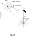
- the target UE 100 may cause its local coordinate system (LCS) and the LCS of supporting UE 110 to be aligned (e.g. as described with reference to operations 201 to 203 of Figure 2 , and/or with reference to Figures 11 and 12 ).
- Such alignment may, in some examples, be referred to as coordinate system alignment (CSA), and may be such as to cause both UEs to share the same notion as to what an angle of arrival or departure is with respect to a spatial direction.
- CSA coordinate system alignment
- the alignment may be such that angular information (e.g. an angle of arrival of a measured signal) has a consistent meaning at both the target UE and the supporting UE.
- the alignment may be performed prior to performance of the measurements by supporting UE 110 (for instance, but not limited to, in response to a request from target UE 100).
- angular measurements made at the supporting UE may be 'translated' into equivalent measurements for the target UE.
- this alignment process may be referred to as angle domain synchronisation (ADS).
- ADS angle domain synchronisation
- multiple supporting UEs may be caused to align their local coordinate systems with the LCS of a single target UE.
- aspects of the present disclosure relate to aligning the LCS of a supporting UE with that of a target UE, it will be further appreciated that the techniques described herein may be applicable to aligning the LCSs of any particular pair of UEs (e.g. a first UE and a second UE).
- target UE 100 may be referred to as UE(o) and supporting UE 110 may be referred to as UE(z).
- UE(z) For the link z between target UE 100 and supporting UE 110, a time of travel, TOT(z) , may be computed (e.g. as illustrated by operation 213 of Figure 2 ). In some examples, TOT(z) may be computed as half the difference between TD(o) and TD(z).
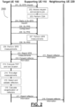
- the supporting UE measurements may be time-aligned with the target UE measurements (e.g. as in operation 214). For instance, this may be achieved by determining a common delay-domain origin using a time of travel for the link between the target UE and the supporting UE. Put another way, the target UE may determine a reference point for the channel response in the delay domain. Aspects of this time-alignment process are described herein with reference to operations S3.1 to S3.3 as depicted in Figure 3 . As illustrated in S3.1 of Figure 3 , the time of travel may be computed as TOT(z) above. Next, in S3.2 the common delay origin may be established by determining an RCI-specific offset referred to as 'dTOT'.
- and dTOT ( z , 0 )
- the first component may correspond to signals propagated via a shortest propagation path between target UE 100 and supporting UE 110 (e.g. but not limited to a line of sight path).
- the delay measurements from the supporting UE and target UE have different delay resolutions. Harmonising these delay resolutions may, in some examples, help to facilitate detection and validation of reflectors as described herein.
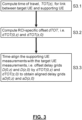
- the target UE measurements and/or the supporting UE measurements may be resampled in the delay domain such that the target UE measurements and the supporting UE measurements have a common delay resolution (also referred to as a 'common sampling rate'). Aspects of this harmonisation process are described herein with reference to Figure 4 .
- the target UE power measurements and the supporting UE power measurements are normalised prior to the resampling.
- This may be referred to as 'power standardisation'.
- the powers may be weighted so that the total power per RCI is equal to 1.
- the measurements may be pruned prior to the resampling.
- a target channel response h(o,z)(t) at time t may be generated based on the target UE measurements and a supporting channel response h(z,o)(t) may be generated based on the supporting UE measurements.
- resampling of the delay measurements may be performed such that the delay resolution of the supporting UE measurements matches that of the target UE measurements.
- the resampling may be performed based on a target channel response and/or supporting channel response as determined above. For instance, the resampling may be achieved by convolving the target channel response and/or the supporting channel response with a filter having the common delay resolution.
- the resampling may be performed by applying, to the target channel response and/or the supporting channel response, a discrete Fourier transform, DFT, followed by an inverse discrete Fourier transform, IDFT, wherein the IDFT has the common delay resolution.
- an association between a component of the target UE measurements and at least one respective component of the supporting UE measurements may be determined based on the time-aligned measurements.
- each component of the target UE measurements is associated with a group or cluster of one or more components of the supporting UE measurements.
- the component of the target UE measurements associated with each cluster is referred to as the 'primary component'. Specific examples of how the association process of S4.3 may be performed are described below with reference to Figures 6 and 7 .
- reflectors in the environment of the UEs may be validated based on their 'visibility' to both the target UE and the supporting UE. That is to say, if a reflection occurs in approximately the same place in measurements performed at both UEs, there is a high likelihood that a ⁇ real' reflector occupies that position in the environment.
- the associated components may be determined to correspond to a particular reflector 150 in an environment of target UE 100.
- the components associated with particular reflector 150 are referred to as the k th component of the UE measurements.
- a distance from target UE 100 to particular reflector 150 may be determined based on the associated components. For instance, if particular reflector 150 corresponds to the k th component of the UE measurements (as mentioned above), and given (x,y) as the position of target UE 100 (e.g. in a global coordinate system, GCS) and (x z , y z ) as the position of supporting UE 110 (e.g.
- target UE 100 may determine a position of particular reflector 150 relative to target UE 100 based on the determined distance and an angle measurement for the corresponding component of the target UE measurements. For instance, such a relative position may be indicated using polar coordinates.
- target UE 100 may receive a signal including information indicative of additional supporting UE measurements of signals (e.g. but not limited to, SL-PRS) transmitted from the target UE to an additional supporting UE (i.e. a nearby UE that is different from target UE 100 and supporting UE 110) via an additional multipath communications channel.
- the additional supporting UE measurements may include delay and angle measurements of the signals transmitted from the target UE to the additional supporting UE via the additional multipath communications channel.
- the additional supporting UE measurements may be performed in a similar manner to the supporting UE measurements described above.
- target UE 100 may time-align the additional supporting UE measurements with additional target UE measurements of signals (e.g. but not limited to, SL-PRS) transmitted from the additional supporting UE to target UE 100 via the additional multipath communications channel.
- the additional target UE measurements may include delay and angle measurements for the signals transmitted from the additional supporting UE to target UE 100 via the additional multipath communications channel.
- the additional target UE measurements may be performed in a similar manner to the target UE measurements described above.
- target UE 100 may determine an additional association between a component of the additional target UE measurements and at least one respective component of the additional supporting UE measurements, wherein the additionally associated components may be determined to correspond to the particular reflector. Moreover, in such examples, the determination of the distance from the target UE to the particular reflector may be further based on the additionally associated components.
- the process described herein may, in some examples, be performed for multiple pairs of UEs in turn, with the results being combined to increase overall effectiveness.
- the reflector charting process described herein may be 'cold-started' by processing all available UEs at the same time.
- the target UE UE(o) may perform the following steps:
- steps e to g above may instead be performed via a joint optimisation process.
- d may correspond to a distance from supporting UE(z) to the reflector plus a distance from reflector to the target UE
- d' may correspond to a distance from supporting UE(y) to the reflector plus a distance from reflector to the target UE.
- the measurement errors may be estimated based on the received measurements or reported by the supporting UEs. It will be appreciated that, in some examples, measurements associated with other UE links (e.g. between UE(z) and UE(y) ) may also be included in the joint optimisation process.
- the process described herein may be 'warm-stafted' by performing the charting process for UE(o) and UE(z) as described above, then refined using the output of the process as applied to combinations ⁇ UE(o), UE(y) ⁇ , as well as ⁇ UE(z), UE(y) ⁇ .
- the process described with reference to Figure 1 may be performed at target UE 100.
- this process may be performed as part of a simultaneous positioning and ranging (SPR) session such as, but not limited to, that described with reference to Figure 2 .
- SPR simultaneous positioning and ranging
- FIG. 2 is a message flow sequence, indicated generally by the reference numeral 200, in accordance with some examples of the described technology.
- the message flow sequence 200 shows an example implementation within which aspects of a process, such as that described with reference to Figure 1 , may be performed.
- the message flow sequence 200 shows a signalling procedure between a target UE, a supporting UE and neighbouring UE 220. However, it will of course be appreciated that some implementations may not involve (or omit) the neighbouring UE 220.
- the target UE and supporting UE may, for example, be target UE 100 and supporting UE 110 described with reference to Figure 1 above.
- the message flow sequence may be triggered by the target UE so as to initiate a simultaneous positioning and ranging (SPR) session with one or more nearby UEs acting as 'supporting UEs'.
- SPR simultaneous positioning and ranging
- a neighbouring UE 220 Whilst various operations are described below as being performed by a neighbouring UE 220, in some examples, such as those in which no neighbouring UE is present, these operations may be performed by a different UE (e.g. but not limited to, the target UE or supporting UE) or may be omitted from the message flow sequence.
- a different UE e.g. but not limited to, the target UE or supporting UE
- the target UE may send to one or more UEs in its environment (which may be referred to as peer UEs), request(s) for simultaneous positioning and ranging (SPR) measurements to be performed by those UEs.
- the request for SPR measurements may be referred to as a request to join an 'SPR session'.
- Such request(s) may be broadcast e.g. via sidelink (SL) and, in some such examples, may be referred to as a SL-SPR request.
- the request may describe which types of SPR measurements are requested from the peer UE for use in the SPR process performed by the target UE.
- the requested SPR measurements may, in some examples, comprise measurements of a sidelink positioning reference signal (SL-PRS) transmitted by the target UE for reception at the peer UE via a wireless communications channel.
- the requested measurements may include timestamps corresponding to reception of the SL-PRS at the peer UE and/or timestamps corresponding to transmission of a reply to the SL-PRS by the peer UE.
- the requested measurements may include a time-difference (TD) between the reception of and reply to the SL-PRS.
- the TD may be referred to as a Rx-Tx time difference.
- the requested measurements may, in some examples, include ranging channel information (RCI).
- RCI ranging channel information
- the RCI may include a channel and/or a CIR and/or a CFR.
- the RCI may include a list of components of the received SL-PRS caused by a multipath propagation environment.
- components of the received signal may correspond to signals received via different paths (e.g. due to reflections caused by other objects in the vicinity).
- the list of components may include arrival angles, propagation delays, and/or powers for each component.
- the components may be referred to as 'relevant reflections'.
- the request for SPR may further include a request for coordinate system alignment (CSA).
- the request for CSA may be sent (e.g. via SL) separately to the request for SPR.
- the request for CSA may include alignment information for use in orienting a local coordinate system, LCS, of the supporting UE to correspond in orientation to an LCS of the target UE. In this way, the local coordinate system of the peer UE may be aligned with that of the target UE in the angle domain.
- the peer UE may assess whether it has the capability (for instance, but not limited to, based on available hardware or software resources) to join the SPR session as a supporting UE.
- the peer UE may transmit a signal to the target UE including information indicative of a confirmation that the peer UE is capable of performing the CSA and/or the SPR measurements.
- the peer UE elects to join the SPR session as a supporting UE
- the peer UE (now a supporting UE) performs CSA with the target UE based on the alignment information included in the request for CSA described above.
- the supporting UE may orient (e.g. rotate) its LCS to correspond in orientation to the LCS of the target UE. This may be such as to cause the supporting UE and target UE to share the same notion as to what an angle of arrival or angle of departure is with respect to a spatial direction.
- the LCS of the supporting UE and the LCS of the target UE may, as a result of performing CSA, share a consistent local angular representation for use in reporting angle measurements.
- the supporting UE may send a reply to the SPR request.
- the reply may include one or more of: an identifier (ID) associated with the supporting UE, a location of the supporting UE, a ranging capability of the supporting UE (e.g. but not limited to, the types of RCI that the supporting UE is capable of measuring), and/or a result of the CSA.
- the result of the CSA may comprise an indication of the extent to which the CSA was successful, and hence the extent to which angle measurements received from the supporting UE can be trusted. In such examples, the indication may sometimes be referred to as a 'trust level'.
- the result of the CSA may include an indication of an accuracy of the CSA (i.e. how well, or to what accuracy/precision the supporting UE expects to have realised the angular alignment of its LCS with that of the target UE).
- the reply may further include a measure of location integrity (e.g. but not limited to a confidence and/or error metric) and/or a location source (such as GNSS, GPS, NR etc.).
- the result of the CSA may be sent by the supporting UE to the target UE (e.g. via SL) separately from the reply to the SPR request. Operations 201 to 204 may together be referred to as a 'signalling handshake'.
- the target UE may send, to the supporting UE, signal(s) including information ("configuration information") for use in configuring a transceiver of the supporting UE to transmit and/or receive the SL-PRS.
- configuration information information
- Such information may, for instance, include sequence, time, frequency and/or periodicity patterns.
- the target UE transmits positioning references signals 206 (e.g. SL-PRS) to the supporting UE.
- SL-PRS may be received via a transceiver configured using the information described with reference to operation 205.
- the supporting UE receives transmitted SL-PRS 206 and may perform some or all of the requested SPR measurements as described with reference to operation 201.
- the supporting UE transmits positioning reference signals (e.g. SL-PRS) to the target UE.
- SL-PRS may be transmitted via a transceiver configured using the information described with reference to operation 205.
- the target UE receives transmitted SL-PRS 208 and may perform some or all of the SPR measurements as described with reference to operation 201. Such measurements may be referred to as target UE measurements.
- the supporting UE transmits signal(s) to the target UE which include information indicative of the SPR measurements performed by the supporting UE at operation 207.
- the supporting UE may receive signal(s) 211 from neighbouring UEs 220. These signals may include information indicative of the locations of one or more reflectors in the environment that are known to the neighbouring UE 220 that sent the signals. Put another way, neighbouring UEs 220 may 'warn' the supporting UE as to the presence of reflectors visible to the neighbouring UEs 220. As will of course be appreciated, some, all or none of the reflectors included in such a 'warning' may be detectable using the measurements described with reference to operations 207 and 209. In some such examples, some or all of this information may be forwarded to target UE at operation 212.
- the information may be forwarded if the signals received from the neighbouring UEs 220 are received with a similar power to that of the SL-PRS from the target, thereby to filter out information from distant neighbouring UEs 220.
- the information may be forwarded if the neighbouring UE obstacle information is similar to the SL-PRS channel (e.g. if the neighbouring UE's obstacles have the same or similar directions to reflections of the SL-PRS from the target), thereby to filter out obstacles which are not in the field of view of the target UE.
- the target UE may directly receive the signal(s) 211 from neighbouring UEs 220.
- These signals may include information indicative of the locations of one or more reflectors in the environment that are known to the neighbouring UE 220 that sent the signals.
- neighbouring UEs 220 may 'warn' the target UE as to the presence of reflectors visible to the neighbouring UEs 220
- the target UE may compute a time of travel (TOT) for the link to the supporting UE based on the SPR measurements described with reference to operations 207 and 209. For instance, the TOT may be determined based on a time difference (TD) for the supporting UE together with a TD for the target UE. In some such examples, the TOT may be calculated as half of the difference between the TD as measured by the supporting UE and the TD as measured by the target UE.
- TOT time of travel
- a location of the target UE may also be obtained.
- the target UE may estimate its location by combining TOTs to multiple supporting UEs (e.g. but not limited to, using multilateration methods).
- the target UE may estimate its own location using a positioning process which is not dependent on radio access technology (RAT).
- RAT radio access technology
- such a process may involve using a global navigation satellite system, GNSS, such as a global positioning system, GPS.
- the target UE may obtain its position from the network (e.g. via a base station) as part of a RAT-dependent process.
- the target UE time-aligns the supporting UE measurements with the target UE measurements.
- this time-alignment may be based on the computed TOT.
- the target UE may offset the delay measurements performed by the supporting UE and the target UE (sometimes referred to as 'delay rasters') using offsets proportional to the computed TOT.
- time-aligning the supporting UE measurements with the target UE measurements may include determining a common delay-domain origin using the computed time of travel for the link between the target UE and the supporting UE. In some examples, such a common delay-domain origin may be determined as described with reference to Figure 1 .
- the target UE may detect and validate reflectors using the time-aligned measurements. For instance, the time-aligned RCI measurements from the target UE and the supporting UE may be compared with one another. In this case, a particular reflector may be considered 'valid' if a channel tap (i.e. a component of the measured signal) is found in both the supporting UE measurements and the target UE measurements at approximately the same aligned delay.
- the target UE may determine, based on the time-aligned measurements, an association between a component of the target UE measurements and at least one respective component of the supporting UE measurements. In this way, the associated components may be determined to correspond to a particular reflector in an environment of the target UE.
- the target UE calculates a distance from the target UE to the reflector(s) detected/validated at operation 215. For instance, such a distance may be calculated based on the associated components determined to correspond to the reflector(s). In some examples, such a distance may be determined as described with reference to Figure 1 . In some examples, a distance from the supporting UE to the reflector(s) may also be calculated by performing a method similar to that described with respect to the target UE.
- the target UE may determine a position of the particular reflector relative to the target UE based on the determined distance and an angle measurement for the corresponding component of the target UE measurements.
- such a relative position may be indicated using polar coordinates.
- the target UE may transmit signal(s) to the supporting UE which include information indicative of the reflector location(s) determined at operation 216.
- the signal(s) may include ranging information indicative of a distance between the supporting UE and the reflector(s).
- the supporting UE may transmit signal(s) to other neighbouring UEs 220 including information indicative of the determined locations of the reflectors.
- the signal(s) transmitted at operation 218 may be similar to the signal(s) transmitted at operation 211 as described above. That is to say, having identified the locations of one or more reflectors in the vicinity of the target UE/supporting UE, the supporting UE may 'warn' neighbouring UEs 220 of the presence and locations of some or all of these reflectors (e.g. based on perceived relevance). In some examples, this transmission may be referred to as an 'obstacle warning SL multicast'.
- the target UE may transmit signal(s) to other neighbouring UEs 220 including information indicative of the determined locations of the reflectors. That is to say, having identified the locations of one or more reflectors in the vicinity of the target UE/supporting UE, the target UE may 'warn' neighbouring UEs 220 of the presence and locations of some or all of these reflectors.
- Figure 5 is a flowchart depicting various operations which may be performed in accordance with various examples.
- the operations depicted in Figure 5 may be executed by a UE device (such as target UE 100 described with reference to Figure 1 ) or other suitable apparatus.
- a UE device such as target UE 100 described with reference to Figure 1
- various operations illustrated in Figure 5 correspond to operations already described with reference to the previous Figures.
- operation S5.1 may correspond to operation 210 described with reference to Figure 2
- operation S5.2 may correspond to operation 214
- operation S5.3 may correspond to operation 215
- operation S5.4 may correspond to operation 216.
- a target UE receives information indicative of measurements (e.g. but not limited to, RCI measurements) of signals transmitted from the target UE to one or more supporting UEs via a multipath communications channel, the measurements being performed by the one or more supporting UEs at which the signals were received.
- the measurements performed by each of the one or more supporting UEs may include a channel periodogram and/or a CIR and/or a CFR.
- the supporting UE measurements may include a list of components (i.e. ⁇ taps') of the measured signals caused by propagation via the multipath communications channel.
- components of the measured signals may correspond to signals received at the supporting UE via different paths (e.g.
- the list of components may include angles of arrival, propagation delays, and/or powers (i.e. gains) for each component.
- the supporting UE measurements may further include information characterising the components in the frequency domain.
- the target UE may align channel rasters among the UEs by (i) determining a common coordinate system for each pair of UEs (e.g. by orienting the LCSs of the one or more supporting UEs to correspond in orientation to the LCS of the target UE), (ii) determining a common delay-domain origin (i.e. reference point for the channel response in the delay domain) for each pair of UEs, and (iii) harmonising the different resolutions (in the delay domain) across the sets of measurements.
- a common coordinate system for each pair of UEs e.g. by orienting the LCSs of the one or more supporting UEs to correspond in orientation to the LCS of the target UE
- determining a common delay-domain origin i.e. reference point for the channel response in the delay domain
- the target UE may perform an identification and vetting (also referred to as detection and validation) of reflectors based on channel reciprocity for each pair of UEs (or, more generally, for each set of UEs). Put another way, the target UE may determine an association between each component of the target UE measurements and at least one respective component of the supporting UE measurements.
- the associated components correspond to reflectors which are common to the target UE measurements and the supporting UE measurements, and may be determined to represent 'validated' (i.e. 'real') reflectors in the vicinity of the target UE.
- this procedure may incorporate information from multiple supporting UEs. For instance, information from multiple UEs may be used in a 'cold started' or 'warm started' combination process as described with reference to Figure 1 .
- the target UE may determine location information for the reflectors identified in operation S5.3. For instance, in some examples, the target UE may determine a distance (sometimes referred to as a 'range') to each of the identified reflectors. In particular, a distance from the target UE to a particular reflector may be determined based on the associated components of the UE measurements. In some examples, the target UE may determine a position of the reflector(s) relative to the target UE based on the determined range and an angle measurement for the corresponding component of the target UE measurements. For instance, in some examples, such a relative position may be indicated using polar coordinates. In some examples, the target UE may combine such a determined relative position with a position of the target UE (e.g. obtained suing GNSS or RAT-based procedures) so as to obtain an absolute position of particular reflector.
- a distance sometimes referred to as a 'range'
- the target UE may determine a position of the reflector(s) relative to the target UE
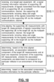
- Figure 6 is a flowchart depicting various operations which may be performed in accordance with various examples.
- the operations depicted in Figure 6 may be executed by a UE device or other suitable apparatus.
- various operations illustrated in Figure 6 correspond to operations already described with reference to the previous Figures.
- all the operations depicted in Figure 6 may be performed as part of operation S4.3 of Figure 4 , part of operation S5.3 of Figure 3 or part of operation 215 in Figure 2 .
- the operations depicted in Figure 6 relate to determining that a component of the target UE measurements is associated with at least one respective component of the supporting UE measurements based on a minimisation of a divergence metric between the component of the target UE measurements and one or more subsets of components of the supporting UE measurements.
- the at least one respective component of the supporting UE measurements may be selected as the subset of the one or more subsets which minimises the divergence metric.
- operation S6.1 the operations described with reference to operations S6.2 to S6.8 are iterated over the components of the target UE measurements. Put another way, for each component s of the target UE measurements, the operations described with reference to operations S6.2 to S6.8 may be performed.
- the target UE measurement component s considered in each iteration may be referred to as the 'primary component'.
- a delay range R(z,o)(s) may be selected from the supporting UE measurements.
- a subset of the time-aligned supporting UE delay measurements aD(z,o) may be selected, the subset being such that the delay of component s (i.e. aD(o,z)(s) ) lies within its range.
- the range R(z,o)(s) may be identified as an interval of fixed width centred on aD(o,z)(s).
- R(z,o)(s) may be selected as an interval that holds a fixed proportion of the total channel energy (e.g. but not limited to, 80% of the channel energy).
- the components of the supporting UE measurements which lie within range R(z,o)(s) may be indexed as r 1 , r 2 , ..., r p , where p is the total number of such components.
- the components r 1 , r 2 , ..., r p may be indexed in order of ascending delays.
- the components r 1 , r 2 , ..., r p may be indexed in order of ascending distance from component s in the delay domain.
- discrete Fourier transforms of one or more channel impulse responses corresponding to subsets of components r 1 , r 2 , ..., r p may be computed. For instance, an FFT of a channel impulse response corresponding to component r 1 may be computed, followed by an FFT of a channel impulse response corresponding to components r 1 and r 2 etc.
- a divergence metric may be evaluated between the Fourier transform of the channel impulse response corresponding to the component s (as determined at operation S6.2) and each of the Fourier transforms of the channel impulse responses corresponding to subsets of components r 1 , r 2 , ..., r p (as computed at operation S6.5).
- the divergence metric may be the mean squared error, MSE.
- MSE mean squared error
- component s (i.e. the primary component) may be associated with the set of supporting UE measurement components r 1 , r 2 , ..., r j that minimises the divergence metric.
- the components r 1 , r 2 , ..., r j are then removed from a search list (i.e. the components of the supporting UE measurements from which the delay range is selected/indexed at operations S6.3 and S6.4).
- the method terminates if each of the components of the target UE measurements have been iterated over as described above, returning an association between each of the components of the target UE measurements with one or more respective components of the supporting UE measurements. Otherwise, the method returns to operation S6.1 and the next component of the target UE measurements may be processed.
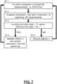
- Figure 7 is a flowchart depicting various operations which may be performed in accordance with various examples.
- the operations depicted in Figure 7 may be executed by a UE device or other suitable apparatus.
- various operations illustrated in Figure 7 correspond to operations already described with reference to the previous Figures.
- all the operations depicted in Figure 7 may be performed as part of operation S4.3 of Figure 4 , part of operation S5.3 of Figure 3 or part of operation 215 in Figure 2 .
- each of the components of the target UE measurements may be associated with a single corresponding component of the supporting UE measurements in the manner described with reference to Figure 7 .
- the operations depicted in Figure 7 relate to determining that a component of the target UE measurements is associated with at least one respective component of the supporting UE measurements based on a delay measurement of the component of the target UE measurement being within a threshold delay of a delay measurement of the at least one respective component of the supporting UE measurements and/or based on a power measurement of the component of the target UE measurement being within a power threshold of a power measurement of the at least one respective component of the supporting UE measurements.
- the operations described with reference to operations S7.2 to S7.5 may be iterated over the components of the target UE measurements. Put another way, for each component s of the target UE measurements, the operations described with reference to operations S7.2 to S7.5 may be performed.
- the target UE measurement component s considered in each iteration may be referred to as the 'primary component'.
- component s of the target UE measurements may be compared with the components of the supporting UE measurements. For instance, the (time-aligned) delay and/or power of the primary component may be compared with the respective delay/power of each component j of the supporting UE measurements.
- the method may be determined whether the compared measurements meet one or more thresholds. If the one or more thresholds are determined to be met, the method proceeds to operation S7.4. Otherwise, the method proceeds to operation S7.5. For instance, the one or more thresholds may be determined to be met if a delay measurement of one or more components of the supporting UE measurements is within a delay threshold of the delay of the component s of the target UE measurements (i.e.
- the one or more thresholds may be determined to be met if a power measurement of one or more components of the supporting UE measurements is within a power threshold of the power of the component s of the target UE measurements (i.e.
- the one or more thresholds may only be determined to be met if both the power and delay thresholds are satisfied (i.e.
- component s may be validated as a ⁇ real' reflector, and the one or more components j of the supporting UE measurements which were determined to meet the one or more thresholds in operation S7.3 are removed from a search list (i.e. the components of the supporting UE measurements which are compared with the primary component in subsequent iterations at operation S7.2).
- component s may be discarded. That is to say, no corresponding reflections have been identified in the supporting UE measurements (i.e. the reciprocal channel) and so the component s is unlikely to correspond to a ⁇ real' reflector in the environment of the target UE.
- the method After performance of operation S7.4 or S7.5, the method returns to operation S7.1 and the next component of the target UE measurements may be processed.
- Figure 8 depicts UE measurements together with time-aligned UE measurements as described with reference to the previous Figures.
- the UE measurements and the time-aligned UE measurements may include delay, D, angle of arrival, A, and power, P, measurements of signals transmitted between a target UE, such as UE 100, and a supporting UE, such as UE 110, via a multipath communications channel.
- Target UE measurements are depicted on axes indicated generally by the reference numeral 810 (on the top-left of Figure 8 ).
- target UE measurements include a first component 811, second component 812, third component 813 and fourth component 814, ordered by increasing delays.
- each of components 811 to 814 may be represented by the triplet D(o,z)(i), A(o,z)(i), P(o,z)(i) , where i runs from 1 to 4.
- supporting UE measurements are depicted on axes indicated generally by the reference numeral 820 (on the bottom-left of Figure 8 ), and include components 821 to 824.
- Reference line 801 serves to illustrate how the delay rasters of the target UE measurements and supporting UE measurements are misaligned. That is to say, the first (i.e. line of sight, LoS) component 811 of the target UE measurements 810 is not aligned with the first (i.e. LoS) component 821 of the supporting UE measurements.
- the first (i.e. line of sight, LoS) component 811 of the target UE measurements 810 is not aligned with the first (i.e. LoS) component 821 of the supporting UE measurements.
- target UE may time-align the supporting UE measurements with the target UE measurements. For instance, a common delay-domain origin may be determined using a time of travel (TOT) for the link between the target UE and the supporting UE.
- TOT time of travel
- time-aligned target UE measurements are depicted on axes indicated generally by the reference numeral 830 (top-right of Figure 8 ), and include components 831 to 834
- time-aligned supporting UE measurements are depicted on axes indicated generally by the reference numeral 840 (both-right of Figure 8 ), and include components 841 to 844.
- the delay raster of the target UE measurements may be aligned with that of the supporting UE measurements. This is apparent from reference line 801, which illustrated as aligned in the time domain with both the first component 831 of the time-aligned target UE measurements and the first component 841 of the time-aligned supporting UE measurements.
- Figure 9 depicts a target UE 910, a supporting UE 920 and reflector 950 on axes indicated generally by the reference numeral 900.
- target UE 910 may correspond to target UE 100
- supporting UE 920 may correspond to supporting UE 110
- reflector 950 may correspond to particular reflector 150.
- location information for the particular reflector 950 may be determined based on associated components of time-aligned UE measurements.
- the location information may be or may comprise a distance between target UE 910 and the reflector.
- the distance between target UE 910 and the reflector is indicated as d 1 ( k )
- the distance between supporting UE 920 and reflector 950 is indicated as d 2 ( k )
- component k of the associated measurements corresponds to reflector 1050.
- d 1 (k) + d 2 (k) d
- d c ⁇ aD ( 0 , z )( k ) is the path distance covered by signals corresponding to the k th component.
- the location of target UE 910 is denoted (x, y)
- the location of reflector 950 is denoted (x o (k), y o (k)
- the location of supporting UE 920 is denoted (x z , y z ).
- Figure 9 depicts A(o,z)(k) as approximately equal to 45 degrees, and A(z,o)(k) as approximately equal to negative 30 degrees (this angle is negative because the LCS of supporting UE 920 has been oriented to correspond to the LCS of target UE 910), though it will of course be appreciated that different relative positions of target UE 910, supporting UE 920 and reflector 950 are possible.
- Figure 10 is a flowchart depicting various operations which may be performed in accordance with various examples. For instance, the operations depicted in Figure 10 may be executed by a UE device or other suitable apparatus. As will of course be appreciated, various operations illustrated in Figure 10 correspond to operations already described with reference to the previous Figures.
- a target UE receives a signal including information indicative of supporting UE measurements of signals transmitted from the target UE to a supporting UE via a multipath communications channel, the supporting UE measurements including delay and angle measurements of the signals transmitted from the target UE to the supporting UE via the multipath communications channel.
- operation S10.1 may correspond to at least operation 210 of Figure 2 and/or operation S5.1 of Figure 3 .
- the supporting UE measurements are time-aligned with target UE measurements of signals transmitted from the supporting UE to the target UE via the multipath communications channel, the target UE measurements including delay and angle measurements for the signals transmitted from the supporting UE to the target UE via the multipath communications channel.
- operation S10.2 may correspond to at least operation 214 of Figure 2 , operation S5.2 of Figure 3 , and/or operation S3.3 of Figure 3 .
- operation S10.3 an association between a component of the target UE measurements and at least one respective component of the supporting UE measurements is determined based on the time-aligned measurements, wherein the associated components are determined to correspond to a particular reflector in an environment of the target UE.
- operation S10.3 may correspond to at least operation 215 of Figure 2 , operation S5.3 of Figure 3 , operation S4.3 of Figure 4 , a combination of operations S6.1 to S6.8 of Figure 6 , and/or a combination of operations S7.1 to S7.5 of Figure 7 .
- location information for the particular reflector is determined based on the associated components.
- operation S10.4 may correspond to at least operation 216 of Figure 2 , and/or operation S5.4 of Figure 3 .
- the location information may include at least one of: a distance and/or angle from the target UE to the particular reflector; a distance and/or angle from the supporting UE to the particular reflector; a distance and/or angle from a neighbouring UE to the particular reflector; a position of the particular reflector with respect to a local coordinate system, LCS, of the target UE, the supporting UE, and/or a neighbouring UE; and/or a position of the particular reflector with respect to a global coordinate system, GCS.
- LCS local coordinate system
- GCS global coordinate system
- Figure 11 depicts example beam arrangements for a first terminal device 1110 (referred to as “first UE” 1110) and a second terminal device 1100 (referred to as “second UE") in the vicinity of reflector 1150.
- second UE 1100 may correspond to at least target UE 100
- first UE 1110 may correspond to at least supporting UE 110
- reflector 1150 may correspond to at least particular reflector 150 described with reference to Figures 1 to 10 .
- Figure 11 will be described in conjunction with Figure 12 , which is a flowchart depicting various operations which may be performed in accordance with various examples. For instance, the operations depicted in Figure 12 may be executed by a UE device or other suitable apparatus. As will of course be appreciated and as discussed further below, various operations illustrated in Figure 12 correspond to operations already described with reference to the previous Figures.
- a UE may cause its local coordinate system (LCS) to be aligned with the LCS of another UE.
- LCS local coordinate system
- a supporting UE may be caused to align its LCS with that of a target UE, as mentioned above, it will be appreciated that such alignment may be performed between any pair of UEs (or, more generally, any plurality of UEs).
- a target UE may be caused to align its LCS with that of a supporting UE.
- Such alignment as described herein may be referred to as 'coordinate system alignment' (CSA) or 'angle domain synchronisation' and may be such as to cause the UEs to share the same notion as to what an angle of arrival or departure is with respect to a spatial direction.
- CSA 'coordinate system alignment'
- 'angle domain synchronisation' may be such as to cause the UEs to share the same notion as to what an angle of arrival or departure is with respect to a spatial direction.
- alignment information is received at a first UE 1110 (e.g. a supporting UE) from a second UE 1100 (e.g. a target UE), for use by first UE 1110 in orienting a local coordinate system, LCS, of first UE 1110 (henceforth referred to as 'LCS 1 ') to correspond in orientation to an LCS of second UE 1100 (henceforth referred to as 'LCS 2 ').
- the alignment information may be included in a request for CSA transmitted over a SL connection from second UE 1100 to first UE 1110.
- the request for CSA may be part of a request for SPR measurements transmitted from second UE 1100.
- the request for CSA and the SPR measurements may be transmitted to first UE 1110 via separate signals transmitted from second UE 1100.
- operation S12.1 may in some implementations correspond at least in part to operation 201 described with reference to Figure 2 .
- first UE 1110 may orient (e.g. rotate) its local coordinate system (LCS 1 ) to correspond in orientation to the LCS (LCS 2 ) of second UE 1100 based on the alignment information received at first UE 1110.
- the alignment information shared between the two UEs is such that they are able to align their coordinate systems to reach a common reference.
- second UE 1100 and first UE 1110 to share the same notion of what an angle (e.g. but not limited to, an angle of departure or angle of arrival) is with respect to a spatial direction.
- angular information at second UE 1100 has the same meaning as at first UE 1110.
- operation S12.2 may correspond operation 203 of Figure 2 .
- angle of arrival measurements at first UE 1110 may comprise an azimuth angle of arrival and/or a zenith angle of arrival for a given receive beam
- angle of departure measurements at second UE 1100 may comprise an azimuth angle of departure and/or a zenith angle of departure for a given transmit beam.
- operation S12.2 may be performed in response to reception, at first UE 1110 from second UE 1100, of a request to orient LCS 1 to correspond in orientation to LCS 2 .
- first UE 1110 may transmit to second UE 1100 an indication that first UE 1110 is capable of orienting LCS 1 to correspond in orientation to LCS 2 . For instance, this may occur before or after performing the orientation of operation S12.2, and may correspond to the confirmation described with reference to operation 202 of Figure 2 .
- the first UE 1110 may then, at operation S12.3, determine, using the oriented LCS of first UE 1110, angle of arrival (AoA) measurements of sidelink signals transmitted from second UE 1100 to first UE 1110 via a multipath communications channel for use in determining location information for at least one reflector in an environment of the first and second UEs.
- the angle of arrival measurements may include measurements of sidelink signals transmitted via a line of sight (LoS) path 1120 and/or paths other than the line of sight path, such as non-LoS path 1130 (e.g. via transmit beam 1102 and reflector 1150).
- LoS line of sight
- the first UE may further determine delay and/or power measurements of the signals transmitted from second UE 1100 to first UE 1110 via the multipath communications channel. It will of course be appreciated that such measurements may correspond to those described with reference to the previous Figures, such as those performed at operation 207 of Figure 2 , and/or those received at operation S5.1 of Figure 5 .
- first UE 1110 transmits to second UE 1100 information indicative of the determined angle of arrival measurements for use in determining location information for a reflector in an environment of second UE 1100. It will of course be appreciated that such location information for the reflector may be determined as described with reference to the previous Figures. For instance, operation S12.4 may in some implementations correspond to operation 210 of Figure 2 .
- the alignment information included in the signal received at first UE 1110 from second UE 1100 may be indicative of an orientation of LCS 2 with respect to a global coordinate system (GCS).
- GCS global coordinate system
- the GCS may correspond to a spatial reference direction (e.g. North), and may be pre-agreed between the UEs (e.g. as part of a standard).
- LCS 1 may be oriented to correspond to LCS 2 in orientation by orienting (e.g. rotating) LCS 1 such that an orientation of LCS 1 with respect to the GCS corresponds to the orientation of LCS 2 with respect to the GCS indicated by the alignment information.
- the orientation of LCSs with respect to the GCS may be determined via various means, such as, but not limited to, using a magnetometer, compass circuitry, inertial measurement unit (IMU), or other suitable means included in the supporting UE device.
- a magnetometer compass circuitry
- IMU inertial measurement unit
- ⁇ 1 the orientation of LCS 1 (before performance of CSA alignment as described herein) with respect to the GCS is denoted by ⁇ 1 and the orientation of LCS 2 with respect to the GCS is denoted by ⁇ 2 .
- ⁇ 2 the orientation of LCS 2 with respect to the GCS is denoted by ⁇ 2 .
- a value of ⁇ 2 maybe included in the alignment information.
- first UE may be caused to orient itself such that ⁇ 1 is equal to ⁇ 2 .
- first UE 1110 may make use of the fact that a line of sight receive beam of first UE 1110 is anti-aligned with a line of sight transmit beam of the second UE 1100.
- the term anti-aligned refers to beams whose main lobes lie in the same line but have opposite directions. More generally, first UE 1110 may determine based on the received alignment information, an orientation of a particular transmit beam 1103 of second UE 1100 with respect to the LCS 2 , wherein sidelink signals transmitted via the particular transmit beam 1103 of second UE 1100 along a LoS path 1120 of the multipath communication channel are received via a particular receive beam 1112 of first UE 1110.
- first UE 1110 may orient LCS 1 such that an orientation of particular receive beam 1112 with respect to LCS 1 is anti-aligned with the determined orientation of particular transmit beam 1103 with respect to LCS 2 (i.e. the orientations differ by 180°, sometimes referred to as 'reciprocal' angles).
- alignment of LCS 1 with LCS 2 may be achieved without the need for a magnetometer and/or compass circuitry (or similar means for determining orientation with respect to a GCS).
- the orientation of particular transmit beam 1103 of second UE 1100 may comprise an angle of departure with respect to LCS 2 for signals transmitted via particular transmit beam 1103 of second UE 1100 (e.g. as determined by UE 1110 or reported by second UE 1100), and the orientation of particular receive beam 1112 of first UE 1110 may comprise an angle of arrival with respect to LCS 1 of signals received at particular receive beam 1112 via the LoS path 1120.
- particular transmit beam 1103 may be referred to as a line of sight transmit beam of second UE 1100
- particular receive beam 1112 may be referred to as a line of sight receive beam of first UE 1110.
- particular receive beam 1112 may be identified from among a plurality of receive beams of first UE 1110 based on measurements of sidelink signals received at the plurality of receive beams from target UE 1100 via the multipath communications channel. For instance, particular receive beam 1112 may be identified as being a receive beam among the plurality of receive beams of first UE 1110 having a highest reference signal received power, RSRP, and/or an earliest time of arrival for sidelink signals transmitted from second UE 1100 via the multipath communications channel and received via the plurality of receive beams of first UE 1110.
- RSRP reference signal received power
- sidelink signals propagated via paths other than LoS path 1120, such as path 1130, may be received at beams other than particular receive beam 1112.
- receive beam 1111 may have a lower RSRP and/or later time of arrival as compared to particular receive beam 1112.
- such beams may be referred to as non-line of sight (NLoS) receive beams.
- second UE 1100 may provide alignment information to the first UE, thereby to allow determination of an orientation of at least one transmit beam of the second UE with respect to LCS 2 for use in orienting LCS 1 .
- the alignment information may be indicative of orientations with respect to LCS 2 of one or more respective transmit beams via which sidelink signals are transmitted by the second UE 1100.
- the alignment information may be indicative of identifiers of one or more respective transmit beams via which sidelink signals are transmitted by the second UE 1100 (e.g., by means of TCI states associated with the transmitted sidelink signals).
- these identifiers may be referred to as 'beam identifiers'.
- the alignment information may be indicative of characteristics of sidelink signals transmitted by the second UE 1100 via one or more respective transmit beams having respective orientations with respect to LCS 2 .
- the characteristics may comprise characteristics of data sequences used for encoding the respective sidelink signals (e.g., initialization sequence for a Gold sequence, or root index and cyclic shift for a ZC sequence) and/or time/frequency resources used for transmitting the respective sidelink signals (e.g., slot index/offset, symbol index/offset, symbol length/duration, time periodicity, frequency allocation).
- the alignment information may be indicative of one or more parameter values of a parametric model used at the first UE 1110 to determine characteristics of sidelink signals transmitted by the second UE 1100 via one or more respective transmit beams having respective orientations with respect to LCS 2 .
- the one or more parameter values of the parametric model may comprise at least one of an azimuth angular interval between adjacent transmit beams of the second terminal device; a zenith angular interval between adjacent transmit beams of the second terminal device; an azimuth oversampling factor; and a zenith oversampling factor.
- the alignment information provided to the first UE may be indicative of one or a combination of the types of alignment information described above.
- this alignment information may amount to 'explicit' orientation (i.e. angle of departure) information for at least one transmit beam of the second UE with respect to LCS 2 for use in orienting LCS 1 .
- the alignment information may be 'implicit' information from which the orientations of transmit beams of the second UE 1100 can be determined.
- the alignment information may be indicative of orientations for all or a subset (e.g. based on a velocity/direction of second UE 1100) of the transmit beams of the second UE 1100.
- the alignment information may include an explicit mapping (e.g. a table or function) between orientations of the transmit beams (i.e. angles of departure) of the second UE and information that allows sidelink signals received at first UE 1110 to be identified as having been transmitted from a specific transmit beam of the second UE 1100, such as the above-described beam identifiers or sidelink signal characteristics indicated by the alignment information.
- the first UE 1110 may determine that at least one sidelink signal received at the particular receive beam 1112 of the first UE matches a particular beam identifier or sidelink signal characteristic from among those indicated by the received alignment information.
- an orientation of the particular transmit beam 1103 e.g. LoS transmit beam
- LCS 2 LCS 2
- the corresponding orientation may be determined using the explicit mapping between beam orientations and beam identifiers/signal characteristics included in the alignment information.
- the alignment information provided to the first UE 1110 by the second UE 1100 may further include information for use in determining transmit beam orientations with respect to LCS 2 , transmit beam identifiers, and/or characteristics of sidelink signals transmitted by the second UE 1100.
- the first UE may be able to use the alignment information to infer beam orientations, beam identifiers and/or signal characteristics for sidelink signals transmitted from the second UE via the multipath communication channel.
- received signals may be matched with the inferred beam identifiers and/or signal characteristics to establish their angle of departure.
- the alignment information may further include one or more parameter values of a parametric model used at the first UE 1110 to determine characteristics of sidelink signals transmitted by the second UE 1100 via one or more respective transmit beams having respective orientations with respect to the LCS of the second UE 1100.
- a parametric model used at the first UE 1110 to determine characteristics of sidelink signals transmitted by the second UE 1100 via one or more respective transmit beams having respective orientations with respect to the LCS of the second UE 1100.
- a parametric model may be used at the first UE to determine characteristics of sidelink signals received from the second UE, but it may also be used at the second UE in the generation of such sidelink signals (e.g. but not limited to, SL-PRS).
- the one or more parameter values may include information for use in generating SL-PRS sequences (e.g. initialisation data for Gold sequences, root sequence index and cyclic shift values for ZC sequences), and/or time/frequency resources (e.g. slot offset, symbol offset, frequency offset) for use based on the angle or beam index of the transmit beam.
- information for use in generating SL-PRS sequences e.g. initialisation data for Gold sequences, root sequence index and cyclic shift values for ZC sequences
- time/frequency resources e.g. slot offset, symbol offset, frequency offset
- the first UE may use the alignment information to determine one or more additional orientations of transmit beams of the second UE, and/or one or more corresponding additional beam identifiers/sidelink signal characteristics.
- the first UE 1110 may then determine that at least one sidelink signal received at the particular receive beam 1112 of the first UE matches a particular beam identifier/sidelink signal characteristic of the one or more additional transmit beam identifiers/sidelink signal characteristics.
- the orientation of the particular transmit beam 1103 of second UE 1100 with respect to the LCS 2 may then be determined to be an orientation from among the one or more additional orientations of transmit beams of the second UE 1100 which corresponds to the particular beam identifier/sidelink signal characteristic.
- the one or more additional orientations with respect to LCS 2 may be determined based on an orientation of at least one transmit beam of the second UE included in the alignment information (e.g. but not limited to, 'zero-angle' transmit beam 1102) using one or more of: a transmit beam azimuth interval, a transmit beam zenith interval, an azimuth oversampling factor, and/or a zenith oversampling factor.
- the one or more corresponding additional transmit beam identifiers may be determined based on the one or more additional orientations and/or one or more parameter values used for generating signals at the second UE 1100 for transmission to the first UE via the multipath communications channel.
- the alignment information may include transmit beam pattern information.
- the transmit beam pattern information may define an angular separation at the second UE side between adjacent transmit beams. This information may then be used by first UE 1110 in combination with beam-specific measurements performed at the first UE 1110 to estimate the AoD at the second UE 1200.
- transmit beam pattern information may be used in the 'implicit' case described above.
- the first UE may make use of a mapping between beam index and orientation with respect to LCS 2 for a reference beam (e.g.
- the zero angle beam 1102 the zero angle beam 1102
- a function that describes how the orientation of any of the remaining beams may be computed using the index of the remaining beam, the index of the reference beam, and transmit beam pattern information such as the beam width. It will be appreciated that the mapping/function used in this process may be included in the alignment information or be pre-stored at the first UE.
- transmit beam 1103 may be the 90° beam with respect to LCS 2 of second UE 1100
- transmit beam 1102 may be the 45° beam with respect to LCS 2 of second UE 1100
- transmit beam not may be the 0° beam with respect to LCS 2 of second UE 1100 (in this example, positive angles are counterclockwise by convention).
- receive beam 1112 may be the -45° beam with respect to LCS 1 of first UE 1110
- receive beam 1111 may be the 0° beam with respect to LCS 1 of first UE 1110.
- first UE 1110 identifies the LoS receive beam as being receive beam 1112 or the -45° beam with respect to LCS1 of first UE 1110. Also, and based on the alignment information received from second UE 1100, first UE 1110 identifies the LoS transmit beam as being transmit beam 1103 or the 90° beam with respect to LCS 2 of second UE 1100. First UE 1110 then rotates LCS 1 by 45° counterclockwise (see dashed arrow in Figure 11 for LCS 1 ) such as the LoS receive beam 1112 now corresponds to the - 90° beam in the rotated LCS 1 of first UE 1110 (i.e.
- the alignment information received at the first UE may be pre-stored at the first UE.
- one or more orientations of transmit beams of the second UE with respect to the LCS of the second UE may be pre-stored at the first UE.
- the alignment information received at the first UE from the second UE may be indicative of beam identifiers/signal characteristics corresponding to the pre-stored orientations.
- this information may comprise a table or function mapping second UE transmit beam orientations with respect to LCS 2 to beam identifiers.
- the LCS of the first UE 1110 By performing alignment as described, in particular by orienting the LCS of the first UE 1110, the LCS of the first UE and the LCS of the second UE share a consistent local angular representation for use in reporting angle measurements.
- supporting UE 1110 may transmit to second UE 1100 a signal including information indicative of a confirmation that first UE 1110 is capable of performing the orientation.
- Figure 13 is a schematic illustration of an example configuration of a computing apparatus 13 which may be configured to perform various operations described with reference to Figures 1 to 812.
- Computing apparatus may comprise control apparatus 1300 which is configured to control operation of other components which form part of the computing apparatus 13 thereby to enable performance of various operations described with reference to Figures 1 to 812.
- the computing apparatus 1300 may comprise processing apparatus 1301 and memory 1302.
- Computer-readable code 1302-2A may be stored on the memory 1302, which when executed by the processing apparatus 1301, causes the control apparatus 1300 to perform any of the operations described herein (e.g. but not limited to those operations attributed to UEs)
- computing apparatus may further include a display 1303, user interactive interface (UII) 1304, radio frequency interface 1305 and global navigation satellite system (GNSS) 1306.
- user interactive interface UII
- GNSS global navigation satellite system
- other satellite communications systems may be used instead of or in addition to GNSS 1306.
- the control apparatus 1300 described above may comprise processing apparatus 1301 communicatively coupled with memory 1302.
- the memory 1302 has computer readable instructions 1302-2A stored thereon, which when executed by the processing apparatus 1301 causes the control apparatus 1300 to cause performance of various ones of the operations described with reference to Figures 1 to 12 .
- the control apparatus 1300 may in some instance be referred to, in general terms, as "apparatus".
- the processing apparatus 1301 may be of any suitable composition and may include one or more processors 1301A of any suitable type or suitable combination of types. Indeed, the term "processing apparatus" should be understood to encompass computers having differing architectures such as single/multi-processor architectures and sequencers/parallel architectures.
- the processing apparatus 1301 may be a programmable processor that interprets computer program instructions 1302-2A and processes data.
- the processing apparatus 1301 may include plural programmable processors.
- the processing apparatus 1301 may be, for example, programmable hardware with embedded firmware.
- the processing apparatus 1301 may alternatively or additionally include one or more specialised circuit such as field programmable gate arrays FPGA, Application Specific Integrated Circuits (ASICs), signal processing devices etc.
- processing apparatus 1301 may be referred to as computing apparatus or processing means.
- the processing apparatus 1301 is coupled to the memory 1302 and is operable to read/write data to/from the memory 1302.
- the memory 1302 may comprise a single memory unit or a plurality of memory units, upon which the computer readable instructions (or code) 1302-2A is stored.
- the memory 1302 may comprise both volatile memory 1302-1 and non-volatile memory 1302-2.
- the computer readable instructions/program code 1302-2A may be stored in the non-volatile memory 1302-2 and may be executed by the processing apparatus 1301 using the volatile memory 1302-1 for temporary storage of data or data and instructions.
- volatile memory include random-access memory (RAM), dynamic random-access memory (DRAM), and synchronous dynamic random-access memory (SDRAM) etc.
- Examples of non-volatile memory include read-only memory (ROM), programmable read-only memory (PROM), electronically erasable programmable read-only memory (EEPROM), flash memory, optical storage, magnetic storage, etc.
- the memory 1302 may be referred to as one or more non-transitory computer readable memory medium or one or more storage devices. Further, the term 'memory', in addition to covering memory comprising both one or more non-volatile memory and one or more volatile memory, may also cover one or more volatile memories only, one or more non-volatile memories only.
- a "memory" or “computer-readable medium” may be any media or means that can contain, store, communicate, propagate or transport the instructions for use by or in connection with an instruction execution system, apparatus, or device, such as a computer.
- the computer readable instructions/program code 1302-2A may be pre-programmed into the control apparatus 1300. Alternatively, the computer readable instructions 1302-2A may arrive at the control apparatus via an electromagnetic carrier signal or may be copied from a physical entity 14 such as a computer program product, a memory device or a record medium such as a compact disc read-only memory (CD-ROM) or digital versatile disc (DVD) an example of which is illustrated in Figure 14 .
- the computer readable instructions 1302-2A may provide the logic and routines that enables the entity/device/apparatus 13 to perform the functionality described above.
- the combination of computer-readable instructions stored on memory may be referred to as a computer program product.
- references to computer program, instructions, code etc. should be understood to express software for a programmable processor firmware such as the programmable content of a hardware device as instructions for a processor or configured or configuration settings for a fixed function device, gate array, programmable logic device, etc.
Landscapes
- Engineering & Computer Science (AREA)
- Radar, Positioning & Navigation (AREA)
- Remote Sensing (AREA)
- Computer Networks & Wireless Communication (AREA)
- Physics & Mathematics (AREA)
- General Physics & Mathematics (AREA)
- Quality & Reliability (AREA)
- Signal Processing (AREA)
- Electromagnetism (AREA)
- Position Fixing By Use Of Radio Waves (AREA)
- Mobile Radio Communication Systems (AREA)
Claims (16)
- Einrichtung, die Folgendes umfasst:Mittel zum Empfangen (210, S5.1, S10.1) eines Signals, das Informationen beinhaltet, die von einer unterstützenden Teilnehmereinrichtung durchgeführte Messungen der unterstützenden UE von Signalen anzeigen, die von einer Ziel-UE via einen Mehrpfadkommunikationskanal zur unterstützenden UE (110, 920) übertragen werden, an der Ziel-UE (100, 910) von der unterstützenden UE, wobei die von der unterstützenden UE durchgeführten Messungen der unterstützenden UE Verzögerungs- und Winkelmessungen der von der Ziel-UE via den Mehrpfadkommunikationskanal zur unterstützenden UE übertragenen Signale beinhalten;Mittel zum zeitlichen Ausrichten (214, S5.2, S10.2) der von der unterstützenden UE durchgeführten Messungen der unterstützenden UE auf die von der Ziel-UE durchgeführten Ziel-UE-Messungen von Signalen, die von der unterstützenden UE via den Mehrpfadkommunikationskanal zur Ziel-UE übertragen werden, wobei die von der Ziel-UE durchgeführten Ziel-UE-Messungen Verzögerungs- und Winkelmessungen für die Signale beinhalten, die von der unterstützenden UE via den Mehrpfadkommunikationskanal zur Ziel-UE übertragen werden;Mittel zum Bestimmen (215, S5.3, S10.3) einer Verknüpfung zwischen einer Komponente der Ziel-UE-Messungen (811-814) und mindestens einer jeweiligen Komponente der Messungen (821-824) der unterstützenden UE durch die Ziel-UE auf Basis der zeitlich ausgerichteten Messungen, wobei bestimmt wird, dass die verknüpften Komponenten einem speziellen Reflektor (150, 950) in einer Umgebung der Ziel-UE entsprechen; undMittel zum Bestimmen (216, S5.4, S10.4) von Standortinformationen für den speziellen Reflektor durch die Ziel-UE auf Basis der verknüpften Komponenten.
- Einrichtung nach Anspruch 1, wobei das zeitliche Ausrichten der Messungen der unterstützenden UE auf die Ziel-UE-Messungen das Bestimmen eines gemeinsamen Verzögerungsdomänenursprungs auf Basis einer Rx-Tx-Zeitdifferenz der Ziel-UE, einer Rx-Tx-Zeitdifferenz der unterstützenden UE, einer kürzesten Verzögerung der Messungen der unterstützenden UE und einer kürzesten Verzögerung der Ziel-UE-Messungen umfasst.
- Einrichtung nach Anspruch 1 oder Anspruch 2, wobei die Messungen der unterstützenden UE ferner Leistungsmessungen der Signale beinhalten, die von der Ziel-UE via den Mehrpfadkommunikationskanal zur unterstützenden UE übertragen werden, und wobei die Ziel-UE-Messungen ferner Leistungsmessungen für die Signale beinhalten, die von der unterstützenden UE via den Mehrpfadkommunikationskanal zur Ziel-UE übertragen werden.
- Einrichtung nach Anspruch 3, wobei die Ziel-UE-Messungen und/oder die Messungen der unterstützenden UE in der Verzögerungsdomäne neu abgetastet werden, derart, dass die Ziel-UE-Messungen und die Messungen der unterstützenden UE eine gemeinsame Verzögerungsauflösung aufweisen, und wobei die Verknüpfung auf Basis der neu abgetasteten Messungen bestimmt wird.
- Einrichtung nach Anspruch 4, wobei die Ziel-UE-Leistungsmessungen und die Leistungsmessungen der unterstützenden UE vor der Neuabtastung beschnitten und/oder normalisiert werden.
- Einrichtung nach Anspruch 4 oder Anspruch 5, wobei die Neuabtastung auf einer Antwort eines Zielkanals, die auf Basis der Ziel-UE-Messungen erzeugt wird, und/oder einer Antwort eines unterstützenden Kanals, die auf Basis der Messungen der unterstützenden UE erzeugt wird, basiert.
- Einrichtung nach Anspruch 6, wobei die Neuabtastung das Falten der Antwort des Zielkanals und/oder der Antwort des unterstützenden Kanals mit einem Filter umfasst, das die gemeinsame Verzögerungsauflösung aufweist.
- Einrichtung nach Anspruch 6, wobei die Neuabtastung das Anwenden einer diskreten Fouriertransformation, DFT, gefolgt von einer inversen diskreten Fouriertransformation, IDFT, auf die Antwort des Zielkanals und/oder die Antwort des unterstützenden Kanals umfasst, wobei die IDFT die gemeinsame Verzögerungsauflösung aufweist.
- Einrichtung nach einem der vorhergehenden Ansprüche, wobei auf Basis einer Minimierung einer Divergenzmetrik zwischen der Komponente der Ziel-UE-Messungen und der mindestens einen jeweiligen Komponente der Messungen der unterstützenden UE bestimmt wird, dass die mindestens eine jeweilige Komponente der Messungen der unterstützenden UE mit der Komponente der Ziel-UE-Messungen verknüpft ist.
- Einrichtung nach einem der vorhergehenden Ansprüche, die ferner Mittel zum Ausrichten eines Koordinatensystems der Ziel-UE auf ein Koordinatensystem der unterstützenden UE auf Basis einer gemeinsamen Referenzrichtung umfasst.
- Einrichtung nach einem der vorhergehenden Ansprüche, wobei auf Basis von einem von Folgendem bestimmt wird, dass die mindestens eine jeweilige Komponente der Messungen der unterstützenden UE mit der Komponente der Ziel-UE-Messungen verknüpft ist:dass eine Verzögerungsmessung der mindestens einen jeweiligen Komponente der Messungen der unterstützenden UE innerhalb einer Schwellwertverzögerung einer Verzögerungsmessung der Komponente der Ziel-UE-Messungen liegt; und/oderdass eine Leistungsmessung der mindestens einen jeweiligen Komponente der Messungen der unterstützenden UE innerhalb einer Schwellwertleistung einer Leistungsmessung der Komponente der Ziel-UE-Messungen liegt.
- Einrichtung nach einem der vorhergehenden Ansprüche, wobei die Standortinformationen für den speziellen Reflektor mindestens eines von Folgendem beinhalten:einen Abstand und/oder einen Winkel von der Ziel-UE zum speziellen Reflektor;einen Abstand und/oder einen Winkel von der unterstützenden UE zum speziellen Reflektor;einen Abstand und/oder einen Winkel von einer benachbarten UE zum speziellen Reflektor;eine Position des speziellen Reflektors mit Bezug auf ein lokales Koordinatensystem, LCS, der Ziel-UE, der unterstützenden UE und/oder einer benachbarten UE; undeine Position des speziellen Reflektors mit Bezug auf ein globales Koordinatensystem, GCS.
- Einrichtung nach einem der vorhergehenden Ansprüche, die ferner Folgendes umfasst:Mittel zum Empfangen eines Signals, das Informationen beinhaltet, die von einer zusätzlichen unterstützenden Teilnehmereinrichtung durchgeführte Messungen der unterstützenden UE von Signalen anzeigen, die von einer Ziel-UE via einen zusätzlichen Mehrpfadkommunikationskanal zur zusätzlichen unterstützenden UE übertragen werden, an der Ziel-UE von der zusätzlichen unterstützenden UE, wobei die Messungen der zusätzlichen unterstützenden UE Verzögerungs- und Winkelmessungen der von der Ziel-UE via den zusätzlichen Mehrpfadkommunikationskanal zur zusätzlichen unterstützenden UE übertragenen Signale beinhalten;Mittel zum zeitlichen Ausrichten der von der zusätzlichen unterstützenden UE durchgeführten Messungen der zusätzlichen unterstützenden UE auf die von der Ziel-UE durchgeführten zusätzlichen Ziel-UE-Messungen von Signalen, die von der zusätzlichen unterstützenden UE via den zusätzlichen Mehrpfadkommunikationskanal zur Ziel-UE übertragen werden, wobei die Ziel-UE-Messungen Verzögerungs- und Winkelmessungen für die Signale beinhalten, die von der zusätzlichen unterstützenden UE via den zusätzlichen Mehrpfadkommunikationskanal zur Ziel-UE übertragen werden; undMittel zum Bestimmen einer zusätzlichen Verknüpfung zwischen einer Komponente der zusätzlichen Ziel-UE-Messungen und mindestens einer jeweiligen Komponente der zusätzlichen Messungen der unterstützenden UE durch die Ziel-UE auf Basis der zusätzlichen zeitlich ausgerichteten Messungen, wobei bestimmt wird, dass die zusätzlich verknüpften Komponenten dem speziellen Reflektor entsprechen,wobei die Bestimmung der Standortinformationen für den speziellen Reflektor durch die Ziel-UE ferner auf den zusätzlich verknüpften Komponenten basiert.
- Einrichtung nach einem der vorhergehenden Ansprüche, wobei die Mittel Folgendes umfassen: mindestens einen Prozessor und mindestens einen Speicher, in dem Anweisungen gespeichert sind, die, wenn sie von dem mindestens einen Prozessor ausgeführt werden, die Durchführung der Einrichtung nach einem der vorhergehenden Ansprüche veranlassen.
- Teilnehmereinrichtungsvorrichtung, die die Einrichtung von einem der vorhergehenden Ansprüche beinhaltet.
- Verfahren, das Folgendes umfasst:Empfangen (210, S5.1, S10.1) eines Signals, das Informationen beinhaltet, die von einer unterstützenden Teilnehmereinrichtung durchgeführte Messungen einer unterstützenden UE von Signalen anzeigen, die von einer Ziel-UE via einen Mehrpfadkommunikationskanal zur unterstützenden UE (110, 920) übertragen werden, an der Ziel-UE (100, 910) von der unterstützenden UE, wobei die von der unterstützenden UE durchgeführten Messungen der unterstützenden UE Verzögerungs- und Winkelmessungen der von der Ziel-UE via den Mehrpfadkommunikationskanal zur unterstützenden UE übertragenen Signale beinhalten;zeitliches Ausrichten (214, S5.2, S10.2) der von der unterstützenden UE durchgeführten Messungen der unterstützenden UE auf die von der Ziel-UE durchgeführten Ziel-UE-Messungen von Signalen, die von der unterstützenden UE via den Mehrpfadkommunikationskanal zur Ziel-UE übertragen werden, wobei die von der Ziel-UE durchgeführten Ziel-UE-Messungen Verzögerungs- und Winkelmessungen für die Signale beinhalten, die von der unterstützenden UE via den Mehrpfadkommunikationskanal zur Ziel-UE übertragen werden;Bestimmen (215, S5.3, S10.3) einer Verknüpfung zwischen einer Komponente der Ziel-UE-Messungen (811-814) und mindestens einer jeweiligen Komponente der Messungen (821-824) der unterstützenden UE durch die Ziel-UE auf Basis der zeitlich ausgerichteten Messungen, wobei bestimmt wird, dass die verknüpften Komponenten einem speziellen Reflektor (150, 950) in einer Umgebung der Ziel-UE entsprechen; undBestimmen (216, S5.4, S10.4) von Standortinformationen für den speziellen Reflektor durch die Ziel-UE auf Basis der verknüpften Komponenten.
Priority Applications (2)
| Application Number | Priority Date | Filing Date | Title |
|---|---|---|---|
| EP22178386.3A EP4290273B1 (de) | 2022-06-10 | 2022-06-10 | Verfahren und vorrichtungen in bezug auf drahtlose kommunikation |
| US18/207,381 US12477489B2 (en) | 2022-06-10 | 2023-06-08 | Methods and apparatuses relating to wireless communication |
Applications Claiming Priority (1)
| Application Number | Priority Date | Filing Date | Title |
|---|---|---|---|
| EP22178386.3A EP4290273B1 (de) | 2022-06-10 | 2022-06-10 | Verfahren und vorrichtungen in bezug auf drahtlose kommunikation |
Publications (2)
| Publication Number | Publication Date |
|---|---|
| EP4290273A1 EP4290273A1 (de) | 2023-12-13 |
| EP4290273B1 true EP4290273B1 (de) | 2024-08-07 |
Family
ID=82846133
Family Applications (1)
| Application Number | Title | Priority Date | Filing Date |
|---|---|---|---|
| EP22178386.3A Active EP4290273B1 (de) | 2022-06-10 | 2022-06-10 | Verfahren und vorrichtungen in bezug auf drahtlose kommunikation |
Country Status (2)
| Country | Link |
|---|---|
| US (1) | US12477489B2 (de) |
| EP (1) | EP4290273B1 (de) |
Family Cites Families (8)
| Publication number | Priority date | Publication date | Assignee | Title |
|---|---|---|---|---|
| WO2018031971A1 (en) * | 2016-08-12 | 2018-02-15 | 5D Robotics, Inc. | Ultra-wide band radar and positional node integration |
| WO2020028517A1 (en) | 2018-08-01 | 2020-02-06 | Intel Corporation | Measurements and reporting for user equipment (ue) positioning in wireless networks |
| ES3023164T3 (en) | 2018-10-31 | 2025-05-30 | Fraunhofer Ges Forschung | Proximity awareness in sidelink communications |
| US12192947B2 (en) * | 2019-02-19 | 2025-01-07 | Qualcomm Incorporated | Systems and methods for positioning with channel measurements |
| WO2020229902A1 (en) * | 2019-05-15 | 2020-11-19 | Telefonaktiebolaget Lm Ericsson (Publ) | Line of sight detection based on channel impulse response reported |
| US11350293B2 (en) | 2019-11-26 | 2022-05-31 | Huawei Technologies Co., Ltd. | Systems and methods for estimating locations of signal shadowing obstructions and signal reflectors in a wireless communications network |
| US11754663B2 (en) * | 2020-06-11 | 2023-09-12 | Qualcomm Incorporated | Additional feedback for location detection of device-free objects using wireless communication signals |
| US11689892B2 (en) | 2020-09-04 | 2023-06-27 | Qualcomm Incorporated | Approach to use positioning reference signal(s) (PRS(s)) traveling non line-of-sight (NLOS) transmission paths and map information for positioning of user equipments (UEs) |
-
2022
- 2022-06-10 EP EP22178386.3A patent/EP4290273B1/de active Active
-
2023
- 2023-06-08 US US18/207,381 patent/US12477489B2/en active Active
Also Published As
| Publication number | Publication date |
|---|---|
| US12477489B2 (en) | 2025-11-18 |
| US20230413201A1 (en) | 2023-12-21 |
| EP4290273A1 (de) | 2023-12-13 |
Similar Documents
| Publication | Publication Date | Title |
|---|---|---|
| EP3928117B1 (de) | Systeme und verfahren zur positionierung mit kanalmessungen | |
| Italiano et al. | A tutorial on 5G positioning | |
| US20240284396A1 (en) | Network verified user device position in a wireless communication network | |
| US12057918B2 (en) | Non-line-of-sight path detection for user equipment positioning in wireless networks | |
| CN112639506B (zh) | 位置确定 | |
| EP4162294B1 (de) | Systeme und verfahren zur bistatischen funkbasierten objektpositionserkennung | |
| US20250056488A1 (en) | Enhanced positioning framework including support to ai/ml | |
| US11486959B2 (en) | Scaled TDOA 3D positioning | |
| US20250208280A1 (en) | Wireless angle-based positioning | |
| KR20240138070A (ko) | 무선 주파수 (rf) 감지를 위한 통신 노드들의 결정 | |
| US20250167865A1 (en) | Methods and apparatuses relating to wireless communication | |
| CN113196107A (zh) | 信息处理的方法和终端设备 | |
| WO2024069617A1 (en) | Device orientation and positioning using local and global coordinate systems | |
| US11480646B2 (en) | Signaling of scaled 3D position information | |
| EP4290273B1 (de) | Verfahren und vorrichtungen in bezug auf drahtlose kommunikation | |
| WO2026021155A1 (en) | Sensing configuration for reference signal time difference or doppler difference measurements | |
| WO2026031854A1 (en) | Sensing configuration for reference signal time difference or doppler difference measurements | |
| US12041512B2 (en) | Method and apparatus for positioning using image and radio signals |
Legal Events
| Date | Code | Title | Description |
|---|---|---|---|
| PUAI | Public reference made under article 153(3) epc to a published international application that has entered the european phase |
Free format text: ORIGINAL CODE: 0009012 |
|
| STAA | Information on the status of an ep patent application or granted ep patent |
Free format text: STATUS: EXAMINATION IS IN PROGRESS |
|
| 17P | Request for examination filed |
Effective date: 20230717 |
|
| AK | Designated contracting states |
Kind code of ref document: A1 Designated state(s): AL AT BE BG CH CY CZ DE DK EE ES FI FR GB GR HR HU IE IS IT LI LT LU LV MC MK MT NL NO PL PT RO RS SE SI SK SM TR |
|
| GRAP | Despatch of communication of intention to grant a patent |
Free format text: ORIGINAL CODE: EPIDOSNIGR1 |
|
| STAA | Information on the status of an ep patent application or granted ep patent |
Free format text: STATUS: GRANT OF PATENT IS INTENDED |
|
| INTG | Intention to grant announced |
Effective date: 20240326 |
|
| GRAS | Grant fee paid |
Free format text: ORIGINAL CODE: EPIDOSNIGR3 |
|
| GRAA | (expected) grant |
Free format text: ORIGINAL CODE: 0009210 |
|
| STAA | Information on the status of an ep patent application or granted ep patent |
Free format text: STATUS: THE PATENT HAS BEEN GRANTED |
|
| AK | Designated contracting states |
Kind code of ref document: B1 Designated state(s): AL AT BE BG CH CY CZ DE DK EE ES FI FR GB GR HR HU IE IS IT LI LT LU LV MC MK MT NL NO PL PT RO RS SE SI SK SM TR |
|
| REG | Reference to a national code |
Ref country code: GB Ref legal event code: FG4D |
|
| REG | Reference to a national code |
Ref country code: CH Ref legal event code: EP |
|
| REG | Reference to a national code |
Ref country code: DE Ref legal event code: R096 Ref document number: 602022005103 Country of ref document: DE |
|
| REG | Reference to a national code |
Ref country code: IE Ref legal event code: FG4D |
|
| REG | Reference to a national code |
Ref country code: LT Ref legal event code: MG9D |
|
| REG | Reference to a national code |
Ref country code: NL Ref legal event code: MP Effective date: 20240807 |
|
| PG25 | Lapsed in a contracting state [announced via postgrant information from national office to epo] |
Ref country code: NO Free format text: LAPSE BECAUSE OF FAILURE TO SUBMIT A TRANSLATION OF THE DESCRIPTION OR TO PAY THE FEE WITHIN THE PRESCRIBED TIME-LIMIT Effective date: 20241107 |
|
| REG | Reference to a national code |
Ref country code: AT Ref legal event code: MK05 Ref document number: 1711548 Country of ref document: AT Kind code of ref document: T Effective date: 20240807 |
|
| PG25 | Lapsed in a contracting state [announced via postgrant information from national office to epo] |
Ref country code: FI Free format text: LAPSE BECAUSE OF FAILURE TO SUBMIT A TRANSLATION OF THE DESCRIPTION OR TO PAY THE FEE WITHIN THE PRESCRIBED TIME-LIMIT Effective date: 20240807 Ref country code: NL Free format text: LAPSE BECAUSE OF FAILURE TO SUBMIT A TRANSLATION OF THE DESCRIPTION OR TO PAY THE FEE WITHIN THE PRESCRIBED TIME-LIMIT Effective date: 20240807 Ref country code: PT Free format text: LAPSE BECAUSE OF FAILURE TO SUBMIT A TRANSLATION OF THE DESCRIPTION OR TO PAY THE FEE WITHIN THE PRESCRIBED TIME-LIMIT Effective date: 20241209 Ref country code: GR Free format text: LAPSE BECAUSE OF FAILURE TO SUBMIT A TRANSLATION OF THE DESCRIPTION OR TO PAY THE FEE WITHIN THE PRESCRIBED TIME-LIMIT Effective date: 20241108 Ref country code: PL Free format text: LAPSE BECAUSE OF FAILURE TO SUBMIT A TRANSLATION OF THE DESCRIPTION OR TO PAY THE FEE WITHIN THE PRESCRIBED TIME-LIMIT Effective date: 20240807 |
|
| PG25 | Lapsed in a contracting state [announced via postgrant information from national office to epo] |
Ref country code: BG Free format text: LAPSE BECAUSE OF FAILURE TO SUBMIT A TRANSLATION OF THE DESCRIPTION OR TO PAY THE FEE WITHIN THE PRESCRIBED TIME-LIMIT Effective date: 20240807 |
|
| PG25 | Lapsed in a contracting state [announced via postgrant information from national office to epo] |
Ref country code: LV Free format text: LAPSE BECAUSE OF FAILURE TO SUBMIT A TRANSLATION OF THE DESCRIPTION OR TO PAY THE FEE WITHIN THE PRESCRIBED TIME-LIMIT Effective date: 20240807 |
|
| PG25 | Lapsed in a contracting state [announced via postgrant information from national office to epo] |
Ref country code: IS Free format text: LAPSE BECAUSE OF FAILURE TO SUBMIT A TRANSLATION OF THE DESCRIPTION OR TO PAY THE FEE WITHIN THE PRESCRIBED TIME-LIMIT Effective date: 20241207 Ref country code: AT Free format text: LAPSE BECAUSE OF FAILURE TO SUBMIT A TRANSLATION OF THE DESCRIPTION OR TO PAY THE FEE WITHIN THE PRESCRIBED TIME-LIMIT Effective date: 20240807 |
|
| PG25 | Lapsed in a contracting state [announced via postgrant information from national office to epo] |
Ref country code: HR Free format text: LAPSE BECAUSE OF FAILURE TO SUBMIT A TRANSLATION OF THE DESCRIPTION OR TO PAY THE FEE WITHIN THE PRESCRIBED TIME-LIMIT Effective date: 20240807 |
|
| PG25 | Lapsed in a contracting state [announced via postgrant information from national office to epo] |
Ref country code: RS Free format text: LAPSE BECAUSE OF FAILURE TO SUBMIT A TRANSLATION OF THE DESCRIPTION OR TO PAY THE FEE WITHIN THE PRESCRIBED TIME-LIMIT Effective date: 20241107 Ref country code: ES Free format text: LAPSE BECAUSE OF FAILURE TO SUBMIT A TRANSLATION OF THE DESCRIPTION OR TO PAY THE FEE WITHIN THE PRESCRIBED TIME-LIMIT Effective date: 20240807 |
|
| PG25 | Lapsed in a contracting state [announced via postgrant information from national office to epo] |
Ref country code: RS Free format text: LAPSE BECAUSE OF FAILURE TO SUBMIT A TRANSLATION OF THE DESCRIPTION OR TO PAY THE FEE WITHIN THE PRESCRIBED TIME-LIMIT Effective date: 20241107 Ref country code: PT Free format text: LAPSE BECAUSE OF FAILURE TO SUBMIT A TRANSLATION OF THE DESCRIPTION OR TO PAY THE FEE WITHIN THE PRESCRIBED TIME-LIMIT Effective date: 20241209 Ref country code: PL Free format text: LAPSE BECAUSE OF FAILURE TO SUBMIT A TRANSLATION OF THE DESCRIPTION OR TO PAY THE FEE WITHIN THE PRESCRIBED TIME-LIMIT Effective date: 20240807 Ref country code: NO Free format text: LAPSE BECAUSE OF FAILURE TO SUBMIT A TRANSLATION OF THE DESCRIPTION OR TO PAY THE FEE WITHIN THE PRESCRIBED TIME-LIMIT Effective date: 20241107 Ref country code: NL Free format text: LAPSE BECAUSE OF FAILURE TO SUBMIT A TRANSLATION OF THE DESCRIPTION OR TO PAY THE FEE WITHIN THE PRESCRIBED TIME-LIMIT Effective date: 20240807 Ref country code: LV Free format text: LAPSE BECAUSE OF FAILURE TO SUBMIT A TRANSLATION OF THE DESCRIPTION OR TO PAY THE FEE WITHIN THE PRESCRIBED TIME-LIMIT Effective date: 20240807 Ref country code: IS Free format text: LAPSE BECAUSE OF FAILURE TO SUBMIT A TRANSLATION OF THE DESCRIPTION OR TO PAY THE FEE WITHIN THE PRESCRIBED TIME-LIMIT Effective date: 20241207 Ref country code: HR Free format text: LAPSE BECAUSE OF FAILURE TO SUBMIT A TRANSLATION OF THE DESCRIPTION OR TO PAY THE FEE WITHIN THE PRESCRIBED TIME-LIMIT Effective date: 20240807 Ref country code: GR Free format text: LAPSE BECAUSE OF FAILURE TO SUBMIT A TRANSLATION OF THE DESCRIPTION OR TO PAY THE FEE WITHIN THE PRESCRIBED TIME-LIMIT Effective date: 20241108 Ref country code: FI Free format text: LAPSE BECAUSE OF FAILURE TO SUBMIT A TRANSLATION OF THE DESCRIPTION OR TO PAY THE FEE WITHIN THE PRESCRIBED TIME-LIMIT Effective date: 20240807 Ref country code: ES Free format text: LAPSE BECAUSE OF FAILURE TO SUBMIT A TRANSLATION OF THE DESCRIPTION OR TO PAY THE FEE WITHIN THE PRESCRIBED TIME-LIMIT Effective date: 20240807 Ref country code: BG Free format text: LAPSE BECAUSE OF FAILURE TO SUBMIT A TRANSLATION OF THE DESCRIPTION OR TO PAY THE FEE WITHIN THE PRESCRIBED TIME-LIMIT Effective date: 20240807 Ref country code: AT Free format text: LAPSE BECAUSE OF FAILURE TO SUBMIT A TRANSLATION OF THE DESCRIPTION OR TO PAY THE FEE WITHIN THE PRESCRIBED TIME-LIMIT Effective date: 20240807 |
|
| PG25 | Lapsed in a contracting state [announced via postgrant information from national office to epo] |
Ref country code: DK Free format text: LAPSE BECAUSE OF FAILURE TO SUBMIT A TRANSLATION OF THE DESCRIPTION OR TO PAY THE FEE WITHIN THE PRESCRIBED TIME-LIMIT Effective date: 20240807 Ref country code: SM Free format text: LAPSE BECAUSE OF FAILURE TO SUBMIT A TRANSLATION OF THE DESCRIPTION OR TO PAY THE FEE WITHIN THE PRESCRIBED TIME-LIMIT Effective date: 20240807 |
|
| PG25 | Lapsed in a contracting state [announced via postgrant information from national office to epo] |
Ref country code: EE Free format text: LAPSE BECAUSE OF FAILURE TO SUBMIT A TRANSLATION OF THE DESCRIPTION OR TO PAY THE FEE WITHIN THE PRESCRIBED TIME-LIMIT Effective date: 20240807 |
|
| PG25 | Lapsed in a contracting state [announced via postgrant information from national office to epo] |
Ref country code: CZ Free format text: LAPSE BECAUSE OF FAILURE TO SUBMIT A TRANSLATION OF THE DESCRIPTION OR TO PAY THE FEE WITHIN THE PRESCRIBED TIME-LIMIT Effective date: 20240807 |
|
| PG25 | Lapsed in a contracting state [announced via postgrant information from national office to epo] |
Ref country code: SK Free format text: LAPSE BECAUSE OF FAILURE TO SUBMIT A TRANSLATION OF THE DESCRIPTION OR TO PAY THE FEE WITHIN THE PRESCRIBED TIME-LIMIT Effective date: 20240807 |
|
| REG | Reference to a national code |
Ref country code: DE Ref legal event code: R097 Ref document number: 602022005103 Country of ref document: DE |
|
| PLBE | No opposition filed within time limit |
Free format text: ORIGINAL CODE: 0009261 |
|
| STAA | Information on the status of an ep patent application or granted ep patent |
Free format text: STATUS: NO OPPOSITION FILED WITHIN TIME LIMIT |
|
| PGFP | Annual fee paid to national office [announced via postgrant information from national office to epo] |
Ref country code: DE Payment date: 20250429 Year of fee payment: 4 |
|
| 26N | No opposition filed |
Effective date: 20250508 |
|
| PGFP | Annual fee paid to national office [announced via postgrant information from national office to epo] |
Ref country code: FR Payment date: 20250508 Year of fee payment: 4 |
|
| PG25 | Lapsed in a contracting state [announced via postgrant information from national office to epo] |
Ref country code: SE Free format text: LAPSE BECAUSE OF FAILURE TO SUBMIT A TRANSLATION OF THE DESCRIPTION OR TO PAY THE FEE WITHIN THE PRESCRIBED TIME-LIMIT Effective date: 20240807 |
|
| REG | Reference to a national code |
Ref country code: CH Ref legal event code: H13 Free format text: ST27 STATUS EVENT CODE: U-0-0-H10-H13 (AS PROVIDED BY THE NATIONAL OFFICE) Effective date: 20260127 |
|
| PG25 | Lapsed in a contracting state [announced via postgrant information from national office to epo] |
Ref country code: IT Free format text: LAPSE BECAUSE OF FAILURE TO SUBMIT A TRANSLATION OF THE DESCRIPTION OR TO PAY THE FEE WITHIN THE PRESCRIBED TIME-LIMIT Effective date: 20240807 |
|
| PG25 | Lapsed in a contracting state [announced via postgrant information from national office to epo] |
Ref country code: MC Free format text: LAPSE BECAUSE OF FAILURE TO SUBMIT A TRANSLATION OF THE DESCRIPTION OR TO PAY THE FEE WITHIN THE PRESCRIBED TIME-LIMIT Effective date: 20240807 |
|
| PG25 | Lapsed in a contracting state [announced via postgrant information from national office to epo] |
Ref country code: LU Free format text: LAPSE BECAUSE OF NON-PAYMENT OF DUE FEES Effective date: 20250610 |
|
| REG | Reference to a national code |
Ref country code: BE Ref legal event code: MM Effective date: 20250630 |
|
| PG25 | Lapsed in a contracting state [announced via postgrant information from national office to epo] |
Ref country code: IE Free format text: LAPSE BECAUSE OF NON-PAYMENT OF DUE FEES Effective date: 20250610 |
|
| PG25 | Lapsed in a contracting state [announced via postgrant information from national office to epo] |
Ref country code: RO Free format text: LAPSE BECAUSE OF FAILURE TO SUBMIT A TRANSLATION OF THE DESCRIPTION OR TO PAY THE FEE WITHIN THE PRESCRIBED TIME-LIMIT Effective date: 20240807 Ref country code: BE Free format text: LAPSE BECAUSE OF NON-PAYMENT OF DUE FEES Effective date: 20250630 |