EP4055441B1 - Anzeigevorrichtung mit einstellbarem sichtwinkel - Google Patents
Anzeigevorrichtung mit einstellbarem sichtwinkel Download PDFInfo
- Publication number
- EP4055441B1 EP4055441B1 EP19798305.9A EP19798305A EP4055441B1 EP 4055441 B1 EP4055441 B1 EP 4055441B1 EP 19798305 A EP19798305 A EP 19798305A EP 4055441 B1 EP4055441 B1 EP 4055441B1
- Authority
- EP
- European Patent Office
- Prior art keywords
- electro
- display device
- lens
- optical
- light
- Prior art date
- Legal status (The legal status is an assumption and is not a legal conclusion. Google has not performed a legal analysis and makes no representation as to the accuracy of the status listed.)
- Active
Links
Images


Classifications
-
- G—PHYSICS
- G02—OPTICS
- G02F—OPTICAL DEVICES OR ARRANGEMENTS FOR THE CONTROL OF LIGHT BY MODIFICATION OF THE OPTICAL PROPERTIES OF THE MEDIA OF THE ELEMENTS INVOLVED THEREIN; NON-LINEAR OPTICS; FREQUENCY-CHANGING OF LIGHT; OPTICAL LOGIC ELEMENTS; OPTICAL ANALOGUE/DIGITAL CONVERTERS
- G02F1/00—Devices or arrangements for the control of the intensity, colour, phase, polarisation or direction of light arriving from an independent light source, e.g. switching, gating or modulating; Non-linear optics
- G02F1/01—Devices or arrangements for the control of the intensity, colour, phase, polarisation or direction of light arriving from an independent light source, e.g. switching, gating or modulating; Non-linear optics for the control of the intensity, phase, polarisation or colour
- G02F1/13—Devices or arrangements for the control of the intensity, colour, phase, polarisation or direction of light arriving from an independent light source, e.g. switching, gating or modulating; Non-linear optics for the control of the intensity, phase, polarisation or colour based on liquid crystals, e.g. single liquid crystal display cells
- G02F1/133—Constructional arrangements; Operation of liquid crystal cells; Circuit arrangements
- G02F1/1333—Constructional arrangements; Manufacturing methods
- G02F1/1335—Structural association of cells with optical devices, e.g. polarisers or reflectors
- G02F1/1336—Illuminating devices
- G02F1/133602—Direct backlight
- G02F1/133606—Direct backlight including a specially adapted diffusing, scattering or light controlling members
-
- G—PHYSICS
- G02—OPTICS
- G02F—OPTICAL DEVICES OR ARRANGEMENTS FOR THE CONTROL OF LIGHT BY MODIFICATION OF THE OPTICAL PROPERTIES OF THE MEDIA OF THE ELEMENTS INVOLVED THEREIN; NON-LINEAR OPTICS; FREQUENCY-CHANGING OF LIGHT; OPTICAL LOGIC ELEMENTS; OPTICAL ANALOGUE/DIGITAL CONVERTERS
- G02F1/00—Devices or arrangements for the control of the intensity, colour, phase, polarisation or direction of light arriving from an independent light source, e.g. switching, gating or modulating; Non-linear optics
- G02F1/29—Devices or arrangements for the control of the intensity, colour, phase, polarisation or direction of light arriving from an independent light source, e.g. switching, gating or modulating; Non-linear optics for the control of the position or the direction of light beams, i.e. deflection
- G02F1/294—Variable focal length devices
-
- B—PERFORMING OPERATIONS; TRANSPORTING
- B60—VEHICLES IN GENERAL
- B60K—ARRANGEMENT OR MOUNTING OF PROPULSION UNITS OR OF TRANSMISSIONS IN VEHICLES; ARRANGEMENT OR MOUNTING OF PLURAL DIVERSE PRIME-MOVERS IN VEHICLES; AUXILIARY DRIVES FOR VEHICLES; INSTRUMENTATION OR DASHBOARDS FOR VEHICLES; ARRANGEMENTS IN CONNECTION WITH COOLING, AIR INTAKE, GAS EXHAUST OR FUEL SUPPLY OF PROPULSION UNITS IN VEHICLES
- B60K35/00—Instruments specially adapted for vehicles; Arrangement of instruments in or on vehicles
- B60K35/10—Input arrangements, i.e. from user to vehicle, associated with vehicle functions or specially adapted therefor
-
- B—PERFORMING OPERATIONS; TRANSPORTING
- B60—VEHICLES IN GENERAL
- B60K—ARRANGEMENT OR MOUNTING OF PROPULSION UNITS OR OF TRANSMISSIONS IN VEHICLES; ARRANGEMENT OR MOUNTING OF PLURAL DIVERSE PRIME-MOVERS IN VEHICLES; AUXILIARY DRIVES FOR VEHICLES; INSTRUMENTATION OR DASHBOARDS FOR VEHICLES; ARRANGEMENTS IN CONNECTION WITH COOLING, AIR INTAKE, GAS EXHAUST OR FUEL SUPPLY OF PROPULSION UNITS IN VEHICLES
- B60K35/00—Instruments specially adapted for vehicles; Arrangement of instruments in or on vehicles
- B60K35/20—Output arrangements, i.e. from vehicle to user, associated with vehicle functions or specially adapted therefor
- B60K35/21—Output arrangements, i.e. from vehicle to user, associated with vehicle functions or specially adapted therefor using visual output, e.g. blinking lights or matrix displays
- B60K35/22—Display screens
-
- G—PHYSICS
- G02—OPTICS
- G02F—OPTICAL DEVICES OR ARRANGEMENTS FOR THE CONTROL OF LIGHT BY MODIFICATION OF THE OPTICAL PROPERTIES OF THE MEDIA OF THE ELEMENTS INVOLVED THEREIN; NON-LINEAR OPTICS; FREQUENCY-CHANGING OF LIGHT; OPTICAL LOGIC ELEMENTS; OPTICAL ANALOGUE/DIGITAL CONVERTERS
- G02F1/00—Devices or arrangements for the control of the intensity, colour, phase, polarisation or direction of light arriving from an independent light source, e.g. switching, gating or modulating; Non-linear optics
- G02F1/01—Devices or arrangements for the control of the intensity, colour, phase, polarisation or direction of light arriving from an independent light source, e.g. switching, gating or modulating; Non-linear optics for the control of the intensity, phase, polarisation or colour
- G02F1/13—Devices or arrangements for the control of the intensity, colour, phase, polarisation or direction of light arriving from an independent light source, e.g. switching, gating or modulating; Non-linear optics for the control of the intensity, phase, polarisation or colour based on liquid crystals, e.g. single liquid crystal display cells
- G02F1/133—Constructional arrangements; Operation of liquid crystal cells; Circuit arrangements
- G02F1/1333—Constructional arrangements; Manufacturing methods
- G02F1/1335—Structural association of cells with optical devices, e.g. polarisers or reflectors
- G02F1/1336—Illuminating devices
- G02F1/133602—Direct backlight
- G02F1/133606—Direct backlight including a specially adapted diffusing, scattering or light controlling members
- G02F1/133607—Direct backlight including a specially adapted diffusing, scattering or light controlling members the light controlling member including light directing or refracting elements, e.g. prisms or lenses
-
- G—PHYSICS
- G02—OPTICS
- G02F—OPTICAL DEVICES OR ARRANGEMENTS FOR THE CONTROL OF LIGHT BY MODIFICATION OF THE OPTICAL PROPERTIES OF THE MEDIA OF THE ELEMENTS INVOLVED THEREIN; NON-LINEAR OPTICS; FREQUENCY-CHANGING OF LIGHT; OPTICAL LOGIC ELEMENTS; OPTICAL ANALOGUE/DIGITAL CONVERTERS
- G02F1/00—Devices or arrangements for the control of the intensity, colour, phase, polarisation or direction of light arriving from an independent light source, e.g. switching, gating or modulating; Non-linear optics
- G02F1/01—Devices or arrangements for the control of the intensity, colour, phase, polarisation or direction of light arriving from an independent light source, e.g. switching, gating or modulating; Non-linear optics for the control of the intensity, phase, polarisation or colour
- G02F1/13—Devices or arrangements for the control of the intensity, colour, phase, polarisation or direction of light arriving from an independent light source, e.g. switching, gating or modulating; Non-linear optics for the control of the intensity, phase, polarisation or colour based on liquid crystals, e.g. single liquid crystal display cells
- G02F1/133—Constructional arrangements; Operation of liquid crystal cells; Circuit arrangements
- G02F1/1333—Constructional arrangements; Manufacturing methods
- G02F1/1335—Structural association of cells with optical devices, e.g. polarisers or reflectors
- G02F1/1336—Illuminating devices
- G02F1/133626—Illuminating devices providing two modes of illumination, e.g. day-night
Definitions
- Various examples of the present disclosure generally relate to display devices, and specifically to a display device with adjustable viewing angle.
- a corresponding method for adjusting a viewing angle of a display device, and a vehicle comprising at least one display device according to the present disclosure are provided.
- Conventional techniques for providing dedicated content to a codriver only include statical light control films, such as louver films, prismatic films influencing the angular distribution of a display backlight, with predefined light distributions, i.e. viewing angles of display devices.
- a display device For providing more flexibility and viewing comfort to a user of a display device, it may be desirable to show, for example, navigation and other car relevant information in a public mode, i.e. visible to driver and passenger, and entertainment services in privacy mode, i.e. visible only to one or more passengers.
- Display devices with switchable privacy mode are, for example, switchable light guide systems using dedicated light guide systems for different viewing angles, or Polymer Dispersed Liquid Crystal (PDLC) systems, which can continuously vary between transparent and diffuse light distributions, but usually depend on high operating voltages.
- PDLC Polymer Dispersed Liquid Crystal
- electro-optical beam shaping systems have been demonstrated which include electro-optical diffractive elements, however these systems require coherent light, i.e. laser light, as input.
- Other display types offering adjustable viewing angles are described in US 2017/0219859 A1 and US 2010/0265435 A1 .
- the idea of the presented approach is to provide an advanced display device and a method for operating a display device, which overcome or mitigate at least some the above-identified limitations and drawbacks.
- advantageous features described in the context of a display device with an electro-optical lens array arranged between a display unit may and the user, may be used to improve a display device with an electro-optical lens array arranged between a backlight unit and a display device, and vice versa.
- the projected light of each of the at least one of the plurality of pixels corresponds to the projected light of each of the plurality of backlight light sources.
- a display device with adjustable viewing angle which includes a display unit comprising a plurality of pixels arranged in a 2-dimensional pixel array and emitting light for displaying image information to a user.
- a viewing angle of a display device may correspond to a spatial angle, in which a user looking at the display device can see the image information displayed on the display device.
- a viewing angle may refer to a narrow or broad light distribution over angle of the emitted light of a display device in the far field, wherein each of the electro-optical lenses in an array projects light projects light with the same light distribution, i.e. having the same viewing angle.
- a viewing angle may correspond to an angle, within which the emitted light from a display pixel is projected with a minimum light intensity by an electro-optical lens.
- the projected light may have a light distribution, or light intensity distribution over angular directions, which may have a center, i.e. maximum intensity along the projection axis, and which may further comprise a symmetrical light distribution.
- a viewing angle may be defined by comprising the light intensity distribution until half maximum values of the light intensity, in specific cases until the light intensity drops below limits defined as 25%, 10%, 5%, or 1% of the maximum light intensity.
- a viewing angle may include the light projection direction with the maximum light intensity along the projection axis, and may include all further projection directions, in which the projected light has an intensity higher than 25%, 10%, 5%, or 1% of the maximum light intensity.
- the light distribution may by a symmetrical light distribution, having axial symmetry around a projection axis of an electro-optical lens, or having a mirror symmetry in case of a cylindrical electro-optical lens.
- the viewing angle may be defined as an angular value limiting the outer directions, in which the the light intensity reaches the above defined limits.
- a display unit comprising a plurality of pixels arranged in a 2-dimensional pixel array and emitting light for displaying image information to a user, may be for example an LCD display unit or an OLED display unit, or any other type of display unit as known in the art, which is based on a plurality of pixels arranged in an array for displaying image information contained in an image signal provided to the display device.
- the display device further comprises a plurality of electro-optical lenses.
- the plurality of electro-optical lenses have adjustable focal lengths, or optical power, which can vary dependent on an electrical voltage applied to the electro-optical lenses.
- the electro-optical lenses may have adjustable focal lengths, which can be electrically controlled by applying an electrical field.
- a outer shape of the electro-optical lens may remain unchanged, while the refractive index of the electro-optical lens changes.
- an electro-optical lens may have a predefined optical power portion, which may be provided by upper and/or lower substrates enclosing the LC molecules, and a variable optical power portion provided by different alignments of the LC molecules depending on an variable electrical field.
- an electro-optical lens can have varying optical power, i.e. focal lengths, which are not necessarily symmetrical, and, in general, can provide varying light distributions of projected light, and for example, varying light projecting axes, in dependency of varying electrical voltages applied.
- a selected light distribution may be provided by applying a respective predetermined electrical voltage to the electro-optical lens.
- the plurality of electro-optical lenses are arranged in a 2-dimensional lens array at the display unit, wherein each electro-optical lens is configured to collect the light from at least one of the plurality of pixels and to project the light along a respective lens projection axis of the respective electro-optical lens.
- the electro-optical lenses may be arranged in a planar array, i.e. having a planar surface.
- the plurality of electro-optical lenses may be provided in an integrally formed array, with upper and lower transparent substrates, providing a preset optical power and and additionally an adjustable, varying optical power, for each of the electro-optical lenses.
- Such a lens arrangement may be easier to produce than discrete electro-optical lenses, and may provide a tuneable micro-lens array.
- the lens array is be arranged at the pixel array, such that each lens is associated with at least one pixel and collects the light emitted from each of the at least one associated pixel.
- the lens array and the pixel array may be arranged adjacent to each other, or directly adjacent to each other, i.e. extending parallelly along each other. They may be arranged in a predetermined distance to each other, such that the light from each pixel illuminates the complete lens area.
- each electro-optical lens is adjustable between a public mode, in which the electro-optical lens has a first optical power, or first focal length , in which the electro-optical lens is configured to project the light along the respective lens projection axis within a first viewing angle, and a privacy mode, in which the electro-optical lens has a second optical power, or focal length, different from the first optical power or focal length, in which the electro-optical lens is configured to project the light along the respective lens projection axis within a second viewing angle, smaller than the first viewing angle.
- a smaller viewing angle may refer to a narrower light distribution, along the optical lens projection axis, such that that image information on the display is not visible to a viewer, or user, which looks onto the display device from a direction outside the viewing angle.
- an display device with an adjustable viewing angle which allows to show different information content, for example, to a driver and co-driver of a vehicle, without driver distraction.
- a switchable privacy mode may be provided, wherein it is possible to switch between privacy and public mode as operation modes of the display device.
- a viewing angle may be selectively set according to user preferences or operational states of a vehicle comprising such a display device.
- a display device with adjustable viewing angle which comprises a backlight unit, comprising a plurality of light sources, for illuminating the pixels of the display unit from a side opposite the user, wherein the pixels themselves often do not act as a light source.
- the display device further includes a display unit comprising a plurality of pixels arranged in a 2-dimensional pixel array for displaying image information to a user as described.
- the backlight unit is arranged at a display unit on a side facing away from the user, i.e. projection direction, for illuminating the pixels of the display unit. Therein, the light from the backlight light sources is projected onto, i.e. through, the pixels with a viewing angle.
- the light from the backlight unit may be uncoherent light.
- each electro-optical lens is configured to collect light from at least one of the plurality of light sources and to project the light along a respective lens projection axis onto at least one of the plurality of pixels.
- the lenses are adjustable between a public mode, in which the electro-optical lens is configured to project the light along the respective lens projection axis within a first viewing angle, and a privacy mode, in which the electro-optical lens is configured to project the light along the respective lens projection axis within a second viewing angle, smaller than the first viewing angle.
- the electro-optical lens array may be arranged above or below the display unit, and in such a way either collects light from the pixels and projects the light towards a user, or collects light from the backlight unit light sources and projects the light onto, or through, pixels, wherein different viewing angles of the display device realized.
- the light sources in the backlight unit may be arranged in a light source array, in a plane defined by a x-direction and y-direction corresponding to x- and y- direction of the pixel array and/or the the lens array.
- the light sources may be arranged in the light source array having a light source x- and y- light source pitch in the respective directions.
- the x- and y- light source pitch may be equal to the x- and/or y- pixel and/or lens pitch in the respective directions.
- electro-optical lenses there is a one-to-one correspondence between electro-optical lenses and light sources, i.e. exactly one lens collects light and projects light from exactly one light source.
- an electro-optical lens iss associated with and collects light from a plurality of light sources, and/or projects the collected light onto a plurality of pixels of the display unit.
- a method for operating a display device comprises the following steps.
- a display unit is provided, which comprises a plurality of pixels arranged in a 2-dimensional pixel array emitting light for displaying image information to a user.
- a plurality of electro-optical lenses with adjustable optical power is provided, which are arranged in a 2-dimensional lens array at the display unit.
- each electro-optical lens is configured to collect light from at least one of the plurality of pixels and to project the light along a respective lens projection axis.
- operation mode is determined for the display device.
- each electro-optical lens is adjusted based on the determined operation mode between a public mode, in which the electro-optical lens is configured to project the light along the respective lens projection axis within a first viewing angle, and a privacy mode, in which the electro-optical lens is configured to project the light along the respective lens projection axis within a second viewing angle, smaller than the first viewing angle.
- a further method for operating a display device comprises the following steps.
- a backlight unit is provided comprising a plurality of light sources.
- a display unit is provided comprising a plurality of pixels arranged in a 2-dimensional pixel array for displaying image information to a user.
- a plurality of electro-optical lenses with adjustable optical power is provided, arranged in a 2-dimensional lens array between the backlight unit and the display units.
- each electro-optical lens is configured to collect the light of at least one of the plurality of light sources and to project the light along a respective lens projection axis of each electro optical lens onto at least one of the plurality of pixels.
- operation mode for the display device is determined.
- each electro-optical lens is adjusted based on the determined operation mode between a public mode, in which each electro-optical lens is configured to project the light along the respective lens projection axis within a first viewing angle, and a privacy mode, in which each electro-optical lens is configured to project the light along the respective lens projection axis within a second viewing angle, smaller than the first viewing angle.
- An electronic communication device or a vehicle comprises at least one display device according to the present disclosure.
- display devices of embodiments may be Human-Machine-Interfaces in an automotive environment, specifically in a vehicle, or may be handheld communication devices, or devices having a touch input display operated by a user, the display device is not limited to being used in such devices.
- Conventional techniques for providing dedicated content to a codriver only include statical light control films, such as louver films, prismatic films influencing the angular distribution of a display backlight, with predefined light distributions, i.e. viewing angles of display devices.
- a display device For providing more flexibility and viewing comfort to a user of a display device, it may be desirable to show, for example, navigation and other car relevant information in a public mode, i.e. visible to driver and passenger, and entertainment services in privacy mode, i.e. visible only to one or more passengers.
- Display devices with switchable privacy mode are, for example, switchable light guide systems using dedicated light guide systems for different viewing angles, or Polymer Dispersed Liquid Crystal (PDLC) systems, which can vary between transparent and diffuse light distributions, but usually depend on high operating voltages.
- PDLC Polymer Dispersed Liquid Crystal
- electro-optical beam shaping systems have been demonstrated which include electro-optical diffractive elements, however these systems are based on phase modulation and, therefore, require coherent light, i.e. laser light, as input.
- FIG. 1 schematically illustrates an electro-optical lens 121, as known in the art.
- Electro-optical lenses 121 are electrically driven lenses with tuneable optical power as known in the art, such as Liquid Crystal (LC) lenses.
- LC Liquid Crystal
- Such lenses include a LC layer between transparent substrates, whose optical power can be controlled by applying an operating voltage to the LC layer.
- An alignment state of the liquid crystal layer is changed so as to change the refractive index of the liquid crystal layer and change the refractive power of the liquid crystal lens.
- FIG. 2 schematically illustrates how an optical power of an electro-optical lens 121 is adjusted by applying an electric field, as known in the art.
- the LC layer When an electric field, or an operating voltage, is applied, the LC layer is electrically controlled and utilized to provide a predefined optical power over an optically active area of the electro-optical lens 121 by aligning optically active LC molecules in the LC layer.
- An off-status may refer to a homogeneous layer, and the light may passes through the LC layer directly.
- a large number of electrodes may be arranged on the substrates, and may be used to finely control the electrical field on the LC layer.
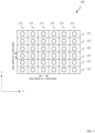
- FIG. 3 schematically illustrates a lens array 120 comprising a plurality of electro-optical lenses 121, according to embodiments of the invention.
- a lens array 120 comprising a plurality of electro-optical lenses 121 is arranged as a 2-dimensional lens array. As depicted in Fig. 3 , the electro-optical lenses 121 are arranged in a rectangular matrix, along an x-direction and a y-direction perpendicular to each other, each electro-optical lens 121 having a rectangular shape.
- the shape of the electro-optical lenses 121 arranged in the lens array 120 is not limited to a specific shape, for example the lenses could also have a hexagonal shape, or could be integrally formed in an array on substrates including a plurality of electrodes, such as a micro-lens arrays.
- the optical active area of an electro-optical lens is not limited to a specific shape.
- the lens array 120 may have a planar surface and may be defined by an x-direction and a y-direction, which are axes perpendicular to each other.
- the electro-optical lenses 121 are arranged in a lens pitch in x-direction
- the electro-optical lenses 121 are arranged in a lens pitch in y-direction.
- the lens pitches denotes the width, or distance, in the respective direction, after which the following lens is arranged.
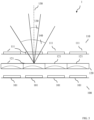
- FIG. 4 schematically illustrates a display device, according to example not forming part of the invention.
- the display device 1 includes a display unit 110 including a plurality of pixels 111 for displaying image information to a user looking at the display device 1.
- the pixels 111 emit light, which is collected and projected forward to a user, or viewer, by optical imaging elements collimating or widening the light into a light beam, such as electro-optical lenses 121.
- the lens array 120 includes a plurality of electro-optical lenses 121, wherein each of the plurality of electro-optical lenses 121 is associated with at least one of the plurality of pixels 111.
- Each electro-optical lens 121 collects the emitted light from the at least one pixel 111 and projects the collected light along an optical projection axis 150 of each electro-optical lens 121.
- each electro-optical lens 121 may collect light from at least one pixel 111, or from a plurality of pixels 111.
- each electro-optical lens may collect and project the light of only one of the plurality of pixels.
- Each electro-optical lens 121 projects the light forward along an optical projection axis 150 within a selected viewing angle 130, 140.
- a first viewing angle 130 bigger or broader then a second viewing angle 140.
- a viewing angle 130,140 may be defined as an angle, in which the display information displayed on the display device can be seen by a user.
- a viewing angle includes all directions, in which the light intensity of the projected light, or a contrast of the display, is over a predefined threshold.
- a predefined threshold may be may be 25%, 10%, 5%, or 1% of the maximum light intensity of the projected light, or the maximum contrast of the display.
- Each electro-optical lens 121 can be configured between a first viewing angle 130 and a second viewing angle 140, which is is narrower than the first viewing angle 130. In various examples, each electro-optical lens 121 can be continuously configured between the two viewing angles, or can be selectively configured to a determined viewing angle. In a public mode, a first broad viewing angle 140 made be chosen, and and a privacy mode, a narrower viewing angle 130 may be chosen.
- viewing angle 130,140 may be an angle including the optical axis 150.
- the optical axis 150 may be the center of the viewing angle 130,140.
- the projected light has a light distribution, or in other words a light intensity distribution over angle, which may be symmetrical to the optical projection axis 150.
- the optical projection axis 150 extends perpendicular to the surface of the display device 1.
- the optical projection axis 115 is directed in a predetermined bias angle from the perpendicular direction at the the surface of the display device 1.
- the electro-optical lenses 121 are configurable such that the optical projection axis 150 of the first viewing angle 130 is in a first direction, and the optical projection axis 150 of the second viewing angle 140 is in a second direction, different from the first direction.
- a maximum of the light intensity may be on the projection axis 150 of an electro-optical lens 121.
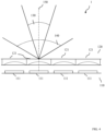
- FIG. 5 schematically illustrates another display device, according to embodiments of the invention.
- the display device 1 includes a backlight unit 100 comprising a plurality of backlight light sources 101.
- the light of the light sources 101 is collected and projected forward onto a plurality of pixels 111 of a display unit 110 by a lens array 120.
- the lens array 120 is arranged between the backlight unit 100 and the display unit 110, wherein each of the electro-optical lenses 121 in the lens array 120 collect the light of at least one of the plurality of light sources 101, and projects the light forward onto, or through, at least one of the plurality of pixels 111.
- the electro-optical lenses 121 can be configured between a public mode and a privacy mode.
- the public mode refers to a first configuration of each of the electro-optical lenses 121, in which the projected light of each of the lenses is projected within a first viewing angle 140.
- the privacy mode to a second configuration of each of the electro-optical lenses 121, in which the projected light of each of the lenses is projected within a second viewing angle 130, which is smaller or narrower than the first viewing angle 140.
- FIG. 6 schematically illustrates a viewing angle 130,140 of a display device 1, according to embodiments of the invention.
- the display device 1 has a surface, on which a user can see the displayed image information. A user looks at the display from a viewing direction relative to the display device 1.
- a viewing angle 130,140 of the display device 1 is defined as including all directions, in which the user can see the image information on the display device 1.
- the viewing angle 130,140 may include an optical projection axis 150, wherein the projected light is projected along the optical projection axis 150.
- a light distribution of the projected light may be symmetrical to the optical projection axis 150, or in other words, the optical projection axis 150 may be in the center of the viewing angle 130,140.
- a bias may be designed into an electro-optical lens. This means the optical projection axis 150 may be offset from the perpendicular by some amount when no electrical field is applied to the electro-optical lens 121.
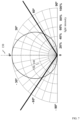
- a viewing angle 130,140 may correspond to the light distribution of the projected light of each of the plurality of pixels 111, as will be explained referring to FIG. 7 , which schematically illustrates a light distribution of an electro-optical lens 121 relative to an optical projection axis 150, according to embodiments of the invention.
- a viewing angle may be characterized by the total shape of the light distribution curve.
- a light distribution curve is a 2D- or polar diagram of the light intensity describing how narrow/broad the light distribution is.
- the projected light of each of the electro-optical lenses 121 has a light distribution over angle with a maximum light intensity, or brightness, at 0°, i.e. along the optical projection axis 150.
- the light intensity diminishes until it reaches 0% of the maximum light intensity at 90°, i.e. in a plane of the electro-optical lens 121.
- a viewing angle 130,140 may be defined as the angle, in which the light intensity is above a light intensity threshold value.
- the light intensity threshold value is 50%.
- the viewing angle includes all directions from -55° to +55°, and is equal to 110° in this example.
- FIG. 8 illustrates a flow chart of a method for operating a display device with adjustable viewing angle, according to embodiments of the invention.
- step S10 a display unit is provided comprising a plurality of pixels arranged in a 2-dimensional pixel array emitting light for displaying image information to a user.
- step S30 a plurality of electro-optical lenses is provided with adjustable optical power arranged in a 2-dimensional lens array at the display unit, wherein each electro-optical lens is configured to collect light from at least one of the plurality of pixels and to project the light along a respective lens projection axis.
- step S40 an operation mode is determined for the display device.
- each electro-optical lens is adjusted based on the determined operation mode between a public mode, in which the electro-optical lens is configured to project the light along the respective lens projection axis within a first viewing angle, and a privacy mode, in which the electro-optical lens is configured to project the light along the respective lens projection axis within a second viewing angle, smaller than the first viewing angle.
- the method ends in step S60.
- FIG. 9 illustrates a flow chart of another method for operating a display device with adjustable viewing angle, according to embodiments of the invention.
- a backlight unit comprising a plurality of light sources.
- a display unit is provided comprising a plurality of pixels arranged in a 2-dimensional pixel array for displaying image information to a user.
- a plurality of electro-optical lenses is provided with adjustable optical power arranged in a 2-dimensional lens array between the backlight unit and the display unit, wherein each electro-optical lens is configured to collect light from at least one of the plurality of light sources to project the light along a respective lens projection axis of each electro-optical lens onto at least one of the plurality of pixels.
- an operation mode is determined for the display device.
- each electro-optical lens is adjusted based on the determined operation mode between a public mode, in which the electro-optical lens is configured to project the light along the respective lens projection axis within a first viewing angle, and a privacy mode, in which the electro-optical lens is configured to project the light along the respective lens projection axis within a second viewing angle, smaller than the first viewing angle.
- the method ends in step T70.
- the light distribution of the projected light of each of the pixels may be the same along the respective optical projection axis.
- the projected light may be distributed having equal viewing angles.
- Each electro-optical lens may be configured to project the light of each of the at least one of the plurality of pixels with a light distribution that covers the complete respective first or second viewing angle.
- the optical axes of each of the plurality of the electro-optical lenses may be parallel to each other. In such a way, the viewing angles, or light distributions of each of the pixels may have the same angular light distributions, such that a high image quality can be ensured.
- the light distribution of the projected light of each of the at least one of the plurality of pixels may be symmetrical with respect to the respective lens projection axis of the associated electro-optical lens, within the respective first or second viewing angle.
- each pixel emits light, which is collected and projected by an associated electro-optical lens along an optical projection axis of the electro-optical lens.
- the projected light of each of the pixels may have the same viewing angle, compared to the projected light of another pixel, of the same or another electro-optical lens.
- the light distribution of the projected light of each of these pixels may have the same beam collimation angle, i.e. viewing angle, and/or the same light distribution, and/or may be projected along the same projection axis of the electro-optical lens.
- the pixel array may be a 2-dimensional pixel array arranged in a plane, in which the pixels may be arranged along a x-direction, and, perpendicular to the x-direction, along a y-direction, wherein the pixels may be arranged along the x-direction having a pixel pitch in x-direction, and along the y-direction having a pixel pitch in y-direction, wherein the lens array may be a 2-dimensional lens array arranged in a plane parallel to the pixel array, in which the electro-optical lenses may be arranged along the x- and y-direction, wherein the electro-optical lenses may be arranged along the x-direction having a lens pitch in x-direction, and along the y-direction having a lens pitch in y-direction, and wherein the lens pitch in x-direction may be the same as, or an integer multiple of, the pixel pitch in x-direction, and the lens pitch in y-dire
- the electro-optical lenses may be electrically driven Liquid Crystal (LC) lenses, which are controlled by by applying an electrical voltage to the electro-optical lens.
- LC Liquid Crystal
- the electro-optical lenses may be integrally formed in a 2-dimensional micro-lens array, having a transparent upper and a lower substrate.
- Each electro-optical lens may be configured to cover the full viewing angle with the projected light of each pixel.
- Each one of the electro-optical lenses may be associated with exactly one pixel, wherein each lens may be associated with a different pixel, and configured to collect and project the light from the associated pixel.
- there may be a one-to-one relationship, or an unambiguous one-to-one association between pixels and lenses, or unique pixel lens pairs, wherein each pixel may be associated with only one lens and each lens may be associated with only one pixel.
- each lens may be associated with a plurality of pixels, wherein every pixel illuminates the complete lens.
- Adjusting the electro-optical lenses may refer to applying an electrical field by an operating voltage to the LC layer, such that the optical power, i.e. focal length, of the lens changes.
- the optical power may change in such a way, that a projection axis of the lens, i.e. the direction, in which the maximum light intensity of the projected light, or the center of the projected light distribution, is projected is changed, or that the viewing angle of the light distribution is changed.
- the association between the electro-optical lenses and the pixels, and the position relative to each other remain unchanged.
- no additional louvers or optical barriers may be used to achieve the optical effect, in particular no interaction effects of louvers or optical barriers with polarization filters may be necessary to achieve the optical effect of varying viewing angles.
- each electro-optical lens may have a respective lens projection axis originating from a center of the electro-optical lens.
- the light of each lens has the same light distribution over angle, i.e. the same viewing angle.
- each lens is located in relation to the at least one associated pixels in such a way, that the light of each of the at least one pixels is collected and projected along the optical projection axis having the same viewing angle and/or light distribution.
- a viewing angle of the display device may be selectively adjustable to one of a plurality of predetermined viewing angles.
- a viewing angle may be solid angle, which may be axially symmetrical around a lens projection axis, and which includes, or limits a light distribution above a predefined threshold intensity.
- the threshold intensity may be defined relative to the maximum intensity of the projected light.
- the projected light of each of the pixels might be projected by a cylindrical electro-optical lens, and thereby might have a mirror symmetry with respect to a plane including the cylinder axis of electro-optical lens and the lens projection axis.
- a light distribution from a pixel may be collimated or widened by complete optical area of an electro-optical lens lens.
- a light beam might be collimated or widened into a light beam with a new light distribution symmetrical about the lens axis, additionally with varying viewing angle, and or varying direction of the lens projection axis, and in general with varying light distribution, however the light of each pixel is projected having the same beam properties, in particular the same projection direction.
- a second viewing angle may, in relation to the first viewing angle, refer to a more focussed light beam, a lower beam divergence, a narrower light distribution.
- the light distributions within the first and/or the second viewing angles may be symmetrical light distributions with respect to the lens axis, which optionally also have varying lens projection axes.
- the public mode may also refer to a state of the electro-optical lens, where the lens has no optical power.
- An optical projection axis may be a symmetry axis of the electro-optical lens, specifically may be orientated in 90° to a surface, in which the electro-optical lens is arranged.
- the lens array may comprises a plurality of identical electro-optical lenses in each direction of lens array.
- the display device may be an on-board display device in a vehicle, and wherein each lens projection axis extends in a direction from the display device towards a codriver position in the vehicle.
- the viewing angle may be directed better towards the intended viewer, thus providing a better image quality.
- the display device may be an on-board display device of a vehicle, wherein at least one of the first viewing angle and the second viewing angle may be determined based on an operating condition of the vehicle, and/or the operation mode may be determined based on user input, or based on a vehicle operation mode.
- the display device may be an on-board display device of a vehicle, wherein the first viewing angle may be determined based on the position of a driver and the position of a codriver in the vehicle, such that the driver and the codriver can see the image information on the display device, and the second viewing angle may be determined based on the positions of the driver and the codriver in the vehicle, such that only the codriver can see the image information on the display device.
- an improved display device by arranging an array of tuneable electro-optical lenses in the display device, such that the viewing angle of the display device may be variably adjusted to a public mode and a privacy mode.
- Embodiments of the present disclosure relate to techniques for a directional backlight, wherein adjustible electro-optical lenses are used, preferably in an integrally formed lens array, with monolithic upper/lower substrates for a plurality of lenses, which may be comprised in or directly adjacent to a backlight unit of a display device.
- a switchable privacy mode may be enabled in a flexible and energy efficient manner for the display device with a low component hight of a switchable directional backlight unit, such that image information may be displayed only to selected users.
Landscapes
- Engineering & Computer Science (AREA)
- Physics & Mathematics (AREA)
- Chemical & Material Sciences (AREA)
- Nonlinear Science (AREA)
- Combustion & Propulsion (AREA)
- Transportation (AREA)
- Mechanical Engineering (AREA)
- General Physics & Mathematics (AREA)
- Optics & Photonics (AREA)
- Mathematical Physics (AREA)
- Crystallography & Structural Chemistry (AREA)
- Liquid Crystal (AREA)
Claims (15)
- Anzeigevorrichtung (1) mit einstellbarem Betrachtungswinkel (130, 140), umfassend:- eine Hintergrundbeleuchtungseinheit (100), die eine Vielzahl von Lichtquellen (101) zum Beleuchten von Pixeln (111) einer Anzeigeeinheit (110) umfasst;- eine Vielzahl von elektrooptischen Linsen (121) mit einstellbarer optischer Leistung, die in einem Linsenarray (120) zwischen der Hintergrundbeleuchtungseinheit (100) und der Anzeigeeinheit (110) angeordnet sind, wobei jede elektrooptische Linse (121) konfiguriert ist, Licht von mindestens einer der Vielzahl von Lichtquellen (101) zu sammeln und das Licht entlang einer jeweiligen Linsenprojektionsachse (150) auf mindestens eines von einer Vielzahl von Pixeln (111) zu projizieren; und- eine Anzeigeeinheit (110), die eine Vielzahl von Pixeln (111) umfasst, die in einem Pixelarray angeordnet sind, um einem Benutzer Bildinformationen anzuzeigen;wobei jede elektrooptische Linse (121) einstellbar ist zwischen:- einem öffentlichen Modus, in dem die elektrooptische Linse (121) konfiguriert ist, das Licht entlang der jeweiligen Linsenprojektionsachse (150) innerhalb eines ersten Betrachtungswinkels (130) zu projizieren, und- einem Privatsphärenmodus, in dem die elektrooptische Linse (121) konfiguriert ist, das Licht entlang der jeweiligen Linsenprojektionsachse (150) innerhalb eines zweiten Betrachtungswinkels (140), der kleiner ist als der erste Betrachtungswinkel (130), zu projizieren,dadurch gekennzeichnet, dassdie optische Projektionsachse (115) in einem vorgegebenen Vorspannungswinkel von einer senkrechten Richtung an der Oberfläche der Anzeigevorrichtung (1) gerichtet ist.
- Anzeigevorrichtung (1) nach Anspruch 1, wobei jede elektrooptische Linse (121) konfiguriert ist, das Licht von jeder der mindestens einer Vielzahl von Lichtquellen (101) mit einer Lichtverteilung zu projizieren, die den gesamten jeweiligen ersten oder zweiten Betrachtungswinkel (130, 140) abdeckt, wobei die optischen Achsen (150) der elektrooptischen Linsen (121) parallel zueinander sind.
- Anzeigevorrichtung (1) nach einem der vorhergehenden Ansprüche, wobei die Lichtverteilung des projizierten Lichts jeder der mindestens einen der Vielzahl von Lichtquellen (101) symmetrisch in Bezug auf die Linsenprojektionsachse (150) innerhalb des jeweiligen ersten oder zweiten Betrachtungswinkels (130, 140) ist.
- Anzeigevorrichtung (1) nach einem der vorhergehenden Ansprüche, wobei das Pixelarray in einer Ebene angeordnet ist, in der die Pixel (111) entlang einer x-Richtung und senkrecht zur x-Richtung entlang einer y-Richtung angeordnet sind, wobei die Pixel (111) entlang der x-Richtung mit einem Pixelabstand in x-Richtung und entlang der y-Richtung mit einem Pixelabstand in y-Richtung angeordnet sind,wobei das Linsenarray (120) in einer zum Pixelarray parallelen Ebene angeordnet ist, in der die elektrooptischen Linsen (121) entlang der x- und y-Richtung angeordnet sind, wobei die elektrooptischen Linsen (121) entlang der x-Richtung mit einem Linsenabstand in x-Richtung und entlang der y-Richtung mit einem Linsenabstand in y-Richtung angeordnet sind, undwobei der Linsenabstand in x-Richtung gleich dem oder ein ganzzahliges Vielfaches des Pixelabstands in x-Richtung ist und der Linsenabstand in y-Richtung gleich dem oder ein ganzzahliges Vielfaches des Pixelabstands in y-Richtung ist.
- Anzeigevorrichtung (1) nach einem der vorhergehenden Ansprüche, wobei jede elektrooptische Linse (121) das Licht von nur einer der Vielzahl von Lichtquellen (101) sammelt und projiziert.
- Anzeigevorrichtung (1) nach einem der vorhergehenden Ansprüche, wobei die elektrooptischen Linsen (121) Flüssigkristall-Linsen (LC-Linsen) sind.
- Anzeigevorrichtung (1) nach einem der vorhergehenden Ansprüche, wobei die elektrooptischen Linsen (121) integral in einem LC-Linsenarray mit monolithischen oberen und unteren Substraten ausgebildet sind, wobei eine elektrooptische Linse (121) einen vordefinierten optischen Leistungsanteil aufweist, der durch die oberen und/oder unteren Substrate bereitgestellt wird, die LC-Moleküle umschließen, und einen variablen optischen Leistungsanteil aufweist, der durch unterschiedliche Ausrichtungen der LC-Moleküle bereitgestellt wird, abhängig von einem variablen elektrischen Feld.
- Anzeigevorrichtung (1) nach einem der vorhergehenden Ansprüche, wobei die Anzeigevorrichtung (1) eine On-Board-Anzeigevorrichtung in einem Fahrzeug ist und wobei sich jede Linsenprojektionsachse (150) in einer Richtung von der Anzeigevorrichtung (1) in Richtung einer Beifahrerposition im Fahrzeug erstreckt.
- Anzeigevorrichtung (1) nach einem der vorhergehenden Ansprüche, wobei die Anzeigevorrichtung (1) eine On-Board-Anzeigevorrichtung eines Fahrzeugs ist und wobei mindestens einer der ersten Betrachtungswinkel (130) und der zweiten Betrachtungswinkel (140) basierend auf einem Betriebszustand des Fahrzeugs bestimmt wird.
- Anzeigevorrichtung (1) nach einem der vorhergehenden Ansprüche, wobei die Anzeigevorrichtung (1) eine On-Board-Anzeigevorrichtung eines Fahrzeugs ist, wobei der erste Betrachtungswinkel (130) basierend auf den Positionen eines Fahrers und eines Beifahrers im Fahrzeug bestimmt wird, sodass der Fahrer und der Beifahrer die Bildinformation auf der Anzeigevorrichtung (1) sehen können, und wobei der zweite Betrachtungswinkel (140) basierend auf den Positionen des Fahrers und des Beifahrers im Fahrzeug bestimmt wird, sodass nur der Beifahrer die Bildinformation auf der Anzeigevorrichtung (1) sehen kann.
- Anzeigevorrichtung (1) mit einstellbarem Betrachtungswinkel (130, 140), umfassend:- eine Anzeigeeinheit (110), die eine Vielzahl von Pixeln (111) umfasst, die in einem Pixelarray angeordnet sind und Licht emittieren, um einem Benutzer Bildinformationen anzuzeigen; und- eine Vielzahl von elektrooptischen Linsen (121) mit einstellbarer optischer Leistung, die in einem Linsenarray (120) an der Anzeigeeinheit (110) angeordnet sind, wobei jede elektrooptische Linse (121) konfiguriert ist, das Licht von mindestens einem der Vielzahl von Pixeln (121) zu sammeln und das Licht entlang einer jeweiligen Linsenprojektionsachse (150) zu projizieren;wobei jede elektrooptische Linse (121) einstellbar ist zwischen:- einem öffentlichen Modus, in dem die elektrooptische Linse (121) konfiguriert ist, das Licht entlang der jeweiligen Linsenprojektionsachse (150) innerhalb eines ersten Betrachtungswinkels (130) zu projizieren, und- einem Privatsphärenmodus, in dem die elektrooptische Linse (121) konfiguriert ist, das Licht entlang der jeweiligen Linsenprojektionsachse (150) innerhalb eines zweiten Betrachtungswinkels (140), der kleiner ist als der erste Betrachtungswinkel (130), zu projizierendadurch gekennzeichnet, dassdie optische Projektionsachse (115) in einem vorgegebenen Vorspannungswinkel von einer senkrechten Richtung an der Oberfläche der Anzeigevorrichtung (1) gerichtet ist.
- Verfahren zum Betrieb einer Anzeigevorrichtung (1) mit einstellbarem Betrachtungswinkel (130, 140), umfassend:- Bereitstellen einer Hintergrundbeleuchtungseinheit (100), die eine Vielzahl von Lichtquellen (101) umfasst;- Bereitstellen einer Anzeigeeinheit (110), die eine Vielzahl von Pixeln (111) umfasst, die in einem Pixelarray angeordnet sind, um einem Benutzer Bildinformationen anzuzeigen; und- Bereitstellen einer Vielzahl von elektrooptischen Linsen (121) mit einstellbarer optischer Leistung, die in einem Linsenarray (120) zwischen der Hintergrundbeleuchtungseinheit (100) und der Anzeigeeinheit (110) angeordnet sind, wobei jede elektrooptische Linse (121) konfiguriert ist, Licht von mindestens einer der Vielzahl von Lichtquellen (101) zu sammeln und das Licht entlang einer jeweiligen Linsenprojektionsachse (150) jeder elektrooptischen Linse (121) auf mindestens eines der Vielzahl von Pixeln (111) zu projizieren,- Bestimmen eines Betriebsmodus der Anzeigevorrichtung;- Anpassen jeder elektrooptischen Linse (121) basierend auf dem bestimmten Betriebsmodus zwischen:dadurch gekennzeichnet, dass- einem öffentlichen Modus, in dem jede elektrooptische Linse (121) konfiguriert ist, das Licht entlang der jeweiligen Linsenprojektionsachse (150) innerhalb eines ersten Betrachtungswinkels (130) zu projizieren, und- einem Privatsphärenmodus, in dem jede elektrooptische Linse (121) konfiguriert ist, das Licht entlang der jeweiligen Linsenprojektionsachse (150) innerhalb eines zweiten Betrachtungswinkels (140), der kleiner ist als der erste Betrachtungswinkel (130), zu projizieren,
die optische Projektionsachse (115) in einem vorgegebenen Vorspannungswinkel von einer senkrechten Richtung an der Oberfläche der Anzeigevorrichtung (1) gerichtet ist. - Verfahren zum Betreiben einer Anzeigevorrichtung (1) mit einstellbarem Betrachtungswinkel (130, 140), umfassend:- Bereitstellen einer Anzeigeeinheit (110), die eine Vielzahl von Pixeln (111) umfasst, die in einem Pixelarray angeordnet sind und Licht emittieren, um einem Benutzer Bildinformationen anzuzeigen; und- Bereitstellen einer Vielzahl von elektrooptischen Linsen (121) mit einstellbarer optischer Leistung, die in einem Linsenarray (120) an der Anzeigeeinheit (110) angeordnet sind, wobei jede elektrooptische Linse (121) konfiguriert ist, Licht von mindestens einem der Vielzahl von Pixeln (121) zu sammeln und das Licht entlang einer jeweiligen Linsenprojektionsachse (150) zu projizieren,- Bestimmen eines Betriebsmodus der Anzeigevorrichtung;- Anpassen jeder elektrooptischen Linse (121) basierend auf dem bestimmten Betriebsmodus zwischen:dadurch gekennzeichnet, dass- einem öffentlichen Modus, in dem die elektrooptische Linse (121) konfiguriert ist, das Licht entlang der jeweiligen Linsenprojektionsachse (150) innerhalb eines ersten Betrachtungswinkels (130) zu projizieren, und- einem Privatsphärenmodus, in dem die elektrooptische Linse (121) konfiguriert ist, das Licht entlang der jeweiligen Linsenprojektionsachse (150) innerhalb eines zweiten Betrachtungswinkels (140), der kleiner ist als der erste Betrachtungswinkel (130), zu projizieren,
die optische Projektionsachse (115) in einem vorgegebenen Vorspannungswinkel von einer senkrechten Richtung an der Oberfläche der Anzeigevorrichtung (1) gerichtet ist. - Verfahren nach Anspruch 12 oder 13, wobei die Anzeigevorrichtung (1) eine On-Board-Anzeigevorrichtung in einem Fahrzeug ist, und wobei der Betriebsmodus basierend auf einer Benutzereingabe oder einem Fahrzeugbetriebsmodus bestimmt wird.
- Fahrzeug, umfassend mindestens eine Anzeigevorrichtung (1) nach Anspruch 1 oder 11.
Applications Claiming Priority (1)
| Application Number | Priority Date | Filing Date | Title |
|---|---|---|---|
| PCT/EP2019/080390 WO2021089138A1 (en) | 2019-11-06 | 2019-11-06 | Display device with adjustable viewing angle |
Publications (2)
| Publication Number | Publication Date |
|---|---|
| EP4055441A1 EP4055441A1 (de) | 2022-09-14 |
| EP4055441B1 true EP4055441B1 (de) | 2025-02-26 |
Family
ID=68468757
Family Applications (1)
| Application Number | Title | Priority Date | Filing Date |
|---|---|---|---|
| EP19798305.9A Active EP4055441B1 (de) | 2019-11-06 | 2019-11-06 | Anzeigevorrichtung mit einstellbarem sichtwinkel |
Country Status (4)
| Country | Link |
|---|---|
| US (1) | US12013623B2 (de) |
| EP (1) | EP4055441B1 (de) |
| CN (1) | CN114600040B (de) |
| WO (1) | WO2021089138A1 (de) |
Families Citing this family (8)
| Publication number | Priority date | Publication date | Assignee | Title |
|---|---|---|---|---|
| US11709411B2 (en) | 2021-07-16 | 2023-07-25 | Meta Platforms Technologies, Llc | Display with image light steering |
| CN118688987A (zh) * | 2023-03-22 | 2024-09-24 | 瀚宇彩晶股份有限公司 | 视角控制装置 |
| CN116047787B (zh) * | 2023-03-30 | 2023-07-07 | 深圳臻像科技有限公司 | 一种高清彩色静态三维显示系统及制备方法 |
| CN118818800A (zh) * | 2023-04-20 | 2024-10-22 | 华为技术有限公司 | 3d显示装置 |
| CN117031814A (zh) * | 2023-07-03 | 2023-11-10 | 联想(北京)有限公司 | 显示装置、处理方法及处理器 |
| CN116798365B (zh) * | 2023-07-12 | 2026-03-17 | 欧摩威汽车电子(芜湖)有限公司 | 用于显示屏的背光调节装置、车载显示器及信息娱乐系统 |
| WO2025032354A1 (en) * | 2023-08-04 | 2025-02-13 | Harman Becker Automotive Systems Gmbh | Systems and methods for adjusting a viewing angle of a display device |
| CN119225000B (zh) * | 2024-11-14 | 2025-09-26 | 重庆赛力斯凤凰智创科技有限公司 | 一种显示屏的显示模式的调节方法和系统 |
Family Cites Families (6)
| Publication number | Priority date | Publication date | Assignee | Title |
|---|---|---|---|---|
| JPH05323307A (ja) | 1992-05-20 | 1993-12-07 | Shunpei Yamazaki | 直視型ディスプレイおよび投光型ディスプレイ |
| US20060238545A1 (en) | 2005-02-17 | 2006-10-26 | Bakin Dmitry V | High-resolution autostereoscopic display and method for displaying three-dimensional images |
| GB2461907A (en) * | 2008-07-17 | 2010-01-20 | Sharp Kk | Angularly restricted display |
| KR20100116079A (ko) * | 2009-04-21 | 2010-10-29 | 삼성전자주식회사 | 가변 확산 필름을 갖는 표시장치 |
| CN106959567A (zh) | 2016-01-08 | 2017-07-18 | 京东方科技集团股份有限公司 | 视角定向光源装置及显示装置 |
| US10705358B2 (en) * | 2016-02-02 | 2020-07-07 | Apple, Inc. | Display apparatus with adjustable angles-of-view comprising backlight structures having an electrically adjustable lens array that adjusts backlight illumination |
-
2019
- 2019-11-06 US US17/774,778 patent/US12013623B2/en active Active
- 2019-11-06 WO PCT/EP2019/080390 patent/WO2021089138A1/en not_active Ceased
- 2019-11-06 CN CN201980101713.8A patent/CN114600040B/zh active Active
- 2019-11-06 EP EP19798305.9A patent/EP4055441B1/de active Active
Also Published As
| Publication number | Publication date |
|---|---|
| WO2021089138A1 (en) | 2021-05-14 |
| US20220382123A1 (en) | 2022-12-01 |
| EP4055441A1 (de) | 2022-09-14 |
| US12013623B2 (en) | 2024-06-18 |
| CN114600040A (zh) | 2022-06-07 |
| CN114600040B (zh) | 2024-07-26 |
Similar Documents
| Publication | Publication Date | Title |
|---|---|---|
| EP4055441B1 (de) | Anzeigevorrichtung mit einstellbarem sichtwinkel | |
| EP1680702B1 (de) | Mehrfachansichtsanzeige | |
| KR100878620B1 (ko) | 광 스위칭 장치 | |
| KR102015590B1 (ko) | 관찰자 추적 방식 디스플레이 | |
| KR20100123710A (ko) | 자동 입체 디스플레이 디바이스 | |
| US10210823B2 (en) | Light deflector and display apparatus | |
| US20200249504A1 (en) | Enhanced privacy switchable backlight system | |
| US20210278663A1 (en) | Head-up display device and image projection unit | |
| JP2020534556A (ja) | 切り替え可能な指向性ディスプレイ向けの光学積層体 | |
| EP2472885A2 (de) | Bildanzeigevorrichtung mit diffraktivem Element | |
| US8982291B2 (en) | Image display device | |
| WO2021113963A1 (en) | Electrode structure for creating electrical potential gradient | |
| US20160011431A1 (en) | Liquid crystal lens device and image display device | |
| JP4950054B2 (ja) | ディスプレイ素子 | |
| WO2005011292A1 (en) | Switchable 2d/3d display | |
| US9557571B2 (en) | Liquid crystal lens device, image display apparatus, drive device, and drive method | |
| KR20190019993A (ko) | 광 편향기 및 디스플레이 장치 | |
| JP2004233659A (ja) | 光偏向素子及び光偏向装置及び画像表示装置 | |
| US12468195B2 (en) | Display device | |
| US12481182B1 (en) | Electronic device | |
| CN119105211B (zh) | 显示组件、显示设备和车辆 | |
| CN119278335A (zh) | 照明装置、车辆用前照灯系统 | |
| HK1107847B (en) | Parallax-reducing, luminance-preserving diffuser | |
| HK1107847A1 (en) | Parallax-reducing, luminance-preserving diffuser |
Legal Events
| Date | Code | Title | Description |
|---|---|---|---|
| STAA | Information on the status of an ep patent application or granted ep patent |
Free format text: STATUS: UNKNOWN |
|
| STAA | Information on the status of an ep patent application or granted ep patent |
Free format text: STATUS: THE INTERNATIONAL PUBLICATION HAS BEEN MADE |
|
| PUAI | Public reference made under article 153(3) epc to a published international application that has entered the european phase |
Free format text: ORIGINAL CODE: 0009012 |
|
| STAA | Information on the status of an ep patent application or granted ep patent |
Free format text: STATUS: REQUEST FOR EXAMINATION WAS MADE |
|
| 17P | Request for examination filed |
Effective date: 20220406 |
|
| AK | Designated contracting states |
Kind code of ref document: A1 Designated state(s): AL AT BE BG CH CY CZ DE DK EE ES FI FR GB GR HR HU IE IS IT LI LT LU LV MC MK MT NL NO PL PT RO RS SE SI SK SM TR |
|
| DAV | Request for validation of the european patent (deleted) | ||
| DAX | Request for extension of the european patent (deleted) | ||
| GRAP | Despatch of communication of intention to grant a patent |
Free format text: ORIGINAL CODE: EPIDOSNIGR1 |
|
| STAA | Information on the status of an ep patent application or granted ep patent |
Free format text: STATUS: GRANT OF PATENT IS INTENDED |
|
| RIC1 | Information provided on ipc code assigned before grant |
Ipc: G02F 1/13357 20060101AFI20241005BHEP |
|
| INTG | Intention to grant announced |
Effective date: 20241107 |
|
| GRAS | Grant fee paid |
Free format text: ORIGINAL CODE: EPIDOSNIGR3 |
|
| GRAA | (expected) grant |
Free format text: ORIGINAL CODE: 0009210 |
|
| STAA | Information on the status of an ep patent application or granted ep patent |
Free format text: STATUS: THE PATENT HAS BEEN GRANTED |
|
| P01 | Opt-out of the competence of the unified patent court (upc) registered |
Free format text: CASE NUMBER: APP_548/2025 Effective date: 20250107 |
|
| AK | Designated contracting states |
Kind code of ref document: B1 Designated state(s): AL AT BE BG CH CY CZ DE DK EE ES FI FR GB GR HR HU IE IS IT LI LT LU LV MC MK MT NL NO PL PT RO RS SE SI SK SM TR |
|
| REG | Reference to a national code |
Ref country code: GB Ref legal event code: FG4D |
|
| REG | Reference to a national code |
Ref country code: CH Ref legal event code: EP |
|
| REG | Reference to a national code |
Ref country code: DE Ref legal event code: R096 Ref document number: 602019066548 Country of ref document: DE |
|
| REG | Reference to a national code |
Ref country code: IE Ref legal event code: FG4D |
|
| REG | Reference to a national code |
Ref country code: NL Ref legal event code: MP Effective date: 20250226 |
|
| PG25 | Lapsed in a contracting state [announced via postgrant information from national office to epo] |
Ref country code: RS Free format text: LAPSE BECAUSE OF FAILURE TO SUBMIT A TRANSLATION OF THE DESCRIPTION OR TO PAY THE FEE WITHIN THE PRESCRIBED TIME-LIMIT Effective date: 20250526 |
|
| PG25 | Lapsed in a contracting state [announced via postgrant information from national office to epo] |
Ref country code: FI Free format text: LAPSE BECAUSE OF FAILURE TO SUBMIT A TRANSLATION OF THE DESCRIPTION OR TO PAY THE FEE WITHIN THE PRESCRIBED TIME-LIMIT Effective date: 20250226 |
|
| PG25 | Lapsed in a contracting state [announced via postgrant information from national office to epo] |
Ref country code: PL Free format text: LAPSE BECAUSE OF FAILURE TO SUBMIT A TRANSLATION OF THE DESCRIPTION OR TO PAY THE FEE WITHIN THE PRESCRIBED TIME-LIMIT Effective date: 20250226 |
|
| PG25 | Lapsed in a contracting state [announced via postgrant information from national office to epo] |
Ref country code: ES Free format text: LAPSE BECAUSE OF FAILURE TO SUBMIT A TRANSLATION OF THE DESCRIPTION OR TO PAY THE FEE WITHIN THE PRESCRIBED TIME-LIMIT Effective date: 20250226 |
|
| REG | Reference to a national code |
Ref country code: LT Ref legal event code: MG9D |
|
| PG25 | Lapsed in a contracting state [announced via postgrant information from national office to epo] |
Ref country code: NO Free format text: LAPSE BECAUSE OF FAILURE TO SUBMIT A TRANSLATION OF THE DESCRIPTION OR TO PAY THE FEE WITHIN THE PRESCRIBED TIME-LIMIT Effective date: 20250526 Ref country code: IS Free format text: LAPSE BECAUSE OF FAILURE TO SUBMIT A TRANSLATION OF THE DESCRIPTION OR TO PAY THE FEE WITHIN THE PRESCRIBED TIME-LIMIT Effective date: 20250626 |
|
| PG25 | Lapsed in a contracting state [announced via postgrant information from national office to epo] |
Ref country code: NL Free format text: LAPSE BECAUSE OF FAILURE TO SUBMIT A TRANSLATION OF THE DESCRIPTION OR TO PAY THE FEE WITHIN THE PRESCRIBED TIME-LIMIT Effective date: 20250226 |
|
| PG25 | Lapsed in a contracting state [announced via postgrant information from national office to epo] |
Ref country code: HR Free format text: LAPSE BECAUSE OF FAILURE TO SUBMIT A TRANSLATION OF THE DESCRIPTION OR TO PAY THE FEE WITHIN THE PRESCRIBED TIME-LIMIT Effective date: 20250226 |
|
| PG25 | Lapsed in a contracting state [announced via postgrant information from national office to epo] |
Ref country code: PT Free format text: LAPSE BECAUSE OF FAILURE TO SUBMIT A TRANSLATION OF THE DESCRIPTION OR TO PAY THE FEE WITHIN THE PRESCRIBED TIME-LIMIT Effective date: 20250626 Ref country code: LV Free format text: LAPSE BECAUSE OF FAILURE TO SUBMIT A TRANSLATION OF THE DESCRIPTION OR TO PAY THE FEE WITHIN THE PRESCRIBED TIME-LIMIT Effective date: 20250226 |
|
| PG25 | Lapsed in a contracting state [announced via postgrant information from national office to epo] |
Ref country code: BG Free format text: LAPSE BECAUSE OF FAILURE TO SUBMIT A TRANSLATION OF THE DESCRIPTION OR TO PAY THE FEE WITHIN THE PRESCRIBED TIME-LIMIT Effective date: 20250226 Ref country code: GR Free format text: LAPSE BECAUSE OF FAILURE TO SUBMIT A TRANSLATION OF THE DESCRIPTION OR TO PAY THE FEE WITHIN THE PRESCRIBED TIME-LIMIT Effective date: 20250527 |
|
| REG | Reference to a national code |
Ref country code: AT Ref legal event code: MK05 Ref document number: 1771207 Country of ref document: AT Kind code of ref document: T Effective date: 20250226 |
|
| PG25 | Lapsed in a contracting state [announced via postgrant information from national office to epo] |
Ref country code: SE Free format text: LAPSE BECAUSE OF FAILURE TO SUBMIT A TRANSLATION OF THE DESCRIPTION OR TO PAY THE FEE WITHIN THE PRESCRIBED TIME-LIMIT Effective date: 20250226 |
|
| PG25 | Lapsed in a contracting state [announced via postgrant information from national office to epo] |
Ref country code: SM Free format text: LAPSE BECAUSE OF FAILURE TO SUBMIT A TRANSLATION OF THE DESCRIPTION OR TO PAY THE FEE WITHIN THE PRESCRIBED TIME-LIMIT Effective date: 20250226 |
|
| PG25 | Lapsed in a contracting state [announced via postgrant information from national office to epo] |
Ref country code: DK Free format text: LAPSE BECAUSE OF FAILURE TO SUBMIT A TRANSLATION OF THE DESCRIPTION OR TO PAY THE FEE WITHIN THE PRESCRIBED TIME-LIMIT Effective date: 20250226 |
|
| PG25 | Lapsed in a contracting state [announced via postgrant information from national office to epo] |
Ref country code: IT Free format text: LAPSE BECAUSE OF FAILURE TO SUBMIT A TRANSLATION OF THE DESCRIPTION OR TO PAY THE FEE WITHIN THE PRESCRIBED TIME-LIMIT Effective date: 20250226 |
|
| PG25 | Lapsed in a contracting state [announced via postgrant information from national office to epo] |
Ref country code: AT Free format text: LAPSE BECAUSE OF FAILURE TO SUBMIT A TRANSLATION OF THE DESCRIPTION OR TO PAY THE FEE WITHIN THE PRESCRIBED TIME-LIMIT Effective date: 20250226 |
|
| PG25 | Lapsed in a contracting state [announced via postgrant information from national office to epo] |
Ref country code: EE Free format text: LAPSE BECAUSE OF FAILURE TO SUBMIT A TRANSLATION OF THE DESCRIPTION OR TO PAY THE FEE WITHIN THE PRESCRIBED TIME-LIMIT Effective date: 20250226 Ref country code: CZ Free format text: LAPSE BECAUSE OF FAILURE TO SUBMIT A TRANSLATION OF THE DESCRIPTION OR TO PAY THE FEE WITHIN THE PRESCRIBED TIME-LIMIT Effective date: 20250226 |
|
| PG25 | Lapsed in a contracting state [announced via postgrant information from national office to epo] |
Ref country code: RO Free format text: LAPSE BECAUSE OF FAILURE TO SUBMIT A TRANSLATION OF THE DESCRIPTION OR TO PAY THE FEE WITHIN THE PRESCRIBED TIME-LIMIT Effective date: 20250226 |
|
| PG25 | Lapsed in a contracting state [announced via postgrant information from national office to epo] |
Ref country code: SK Free format text: LAPSE BECAUSE OF FAILURE TO SUBMIT A TRANSLATION OF THE DESCRIPTION OR TO PAY THE FEE WITHIN THE PRESCRIBED TIME-LIMIT Effective date: 20250226 |
|
| REG | Reference to a national code |
Ref country code: DE Ref legal event code: R097 Ref document number: 602019066548 Country of ref document: DE |
|
| PLBE | No opposition filed within time limit |
Free format text: ORIGINAL CODE: 0009261 |
|
| STAA | Information on the status of an ep patent application or granted ep patent |
Free format text: STATUS: NO OPPOSITION FILED WITHIN TIME LIMIT |
|
| PGFP | Annual fee paid to national office [announced via postgrant information from national office to epo] |
Ref country code: DE Payment date: 20251022 Year of fee payment: 7 |
|
| PGFP | Annual fee paid to national office [announced via postgrant information from national office to epo] |
Ref country code: GB Payment date: 20251023 Year of fee payment: 7 |
|
| 26N | No opposition filed |
Effective date: 20251127 |