EP4055284B1 - Dispositif de fixation - Google Patents
Dispositif de fixation Download PDFInfo
- Publication number
- EP4055284B1 EP4055284B1 EP20816569.6A EP20816569A EP4055284B1 EP 4055284 B1 EP4055284 B1 EP 4055284B1 EP 20816569 A EP20816569 A EP 20816569A EP 4055284 B1 EP4055284 B1 EP 4055284B1
- Authority
- EP
- European Patent Office
- Prior art keywords
- fingers
- finger
- board
- fixing device
- fastener
- Prior art date
- Legal status (The legal status is an assumption and is not a legal conclusion. Google has not performed a legal analysis and makes no representation as to the accuracy of the status listed.)
- Active
Links
- 238000003780 insertion Methods 0.000 claims description 37
- 230000037431 insertion Effects 0.000 claims description 37
- 230000015572 biosynthetic process Effects 0.000 claims description 24
- 238000005755 formation reaction Methods 0.000 claims description 24
- 230000000295 complement effect Effects 0.000 claims description 17
- 239000000463 material Substances 0.000 description 7
- 239000004033 plastic Substances 0.000 description 6
- 229920003023 plastic Polymers 0.000 description 6
- 238000000034 method Methods 0.000 description 5
- 210000002105 tongue Anatomy 0.000 description 5
- 238000009434 installation Methods 0.000 description 4
- 239000002184 metal Substances 0.000 description 4
- 239000011505 plaster Substances 0.000 description 3
- 239000011347 resin Substances 0.000 description 3
- 229920005989 resin Polymers 0.000 description 3
- 239000011449 brick Substances 0.000 description 2
- 239000002991 molded plastic Substances 0.000 description 2
- 239000002023 wood Substances 0.000 description 2
- 239000004743 Polypropylene Substances 0.000 description 1
- 239000000853 adhesive Substances 0.000 description 1
- 230000001070 adhesive effect Effects 0.000 description 1
- 238000004873 anchoring Methods 0.000 description 1
- 239000004566 building material Substances 0.000 description 1
- 238000006243 chemical reaction Methods 0.000 description 1
- 230000000694 effects Effects 0.000 description 1
- 239000002657 fibrous material Substances 0.000 description 1
- 238000004519 manufacturing process Methods 0.000 description 1
- 238000000465 moulding Methods 0.000 description 1
- -1 polypropylene Polymers 0.000 description 1
- 229920001155 polypropylene Polymers 0.000 description 1
- 238000010079 rubber tapping Methods 0.000 description 1
- 239000007787 solid Substances 0.000 description 1
- 239000000758 substrate Substances 0.000 description 1
- 239000011800 void material Substances 0.000 description 1
Images


Classifications
-
- F—MECHANICAL ENGINEERING; LIGHTING; HEATING; WEAPONS; BLASTING
- F16—ENGINEERING ELEMENTS AND UNITS; GENERAL MEASURES FOR PRODUCING AND MAINTAINING EFFECTIVE FUNCTIONING OF MACHINES OR INSTALLATIONS; THERMAL INSULATION IN GENERAL
- F16B—DEVICES FOR FASTENING OR SECURING CONSTRUCTIONAL ELEMENTS OR MACHINE PARTS TOGETHER, e.g. NAILS, BOLTS, CIRCLIPS, CLAMPS, CLIPS OR WEDGES; JOINTS OR JOINTING
- F16B13/00—Dowels or other devices fastened in walls or the like by inserting them in holes made therein for that purpose
- F16B13/04—Dowels or other devices fastened in walls or the like by inserting them in holes made therein for that purpose with parts gripping in the hole or behind the reverse side of the wall after inserting from the front
- F16B13/08—Dowels or other devices fastened in walls or the like by inserting them in holes made therein for that purpose with parts gripping in the hole or behind the reverse side of the wall after inserting from the front with separate or non-separate gripping parts moved into their final position in relation to the body of the device without further manual operation
- F16B13/0808—Dowels or other devices fastened in walls or the like by inserting them in holes made therein for that purpose with parts gripping in the hole or behind the reverse side of the wall after inserting from the front with separate or non-separate gripping parts moved into their final position in relation to the body of the device without further manual operation by a toggle-mechanism
Definitions
- the present invention relates to a fixing device for use with a fastener in making a fixture to a board from a front side of the board at an aperture.
- the invention relates to an expansible anchor (10) for fastening to a panelshaped building material, having an anchor sleeve (12) with forwardly projecting expansion tongues (18) that can be spread open by drawing in an expander body (24) having an expander cone (24).
- the invention proposes to form the expansible anchor (10) with a locking connection (20, 36) which locks the expander body (24) on the expansible anchor (10) in a position in which the expander body (24) is drawn in between the expansion tongues (18) and holds the expansion tongues (18) in a spread-open position.
- the invention has the advantage that the expander body (24) remains in its position in which it is drawn in between the expansion tongues (18) and holds the expansion tongues in a spread-open position even when an expander screw is unscrewed from the expansible anchor (10).
- This invention is a wall fastener to join abutting surfaces such as affixing a bracket to a wall.
- the L-shape arms of the fastener are attached with hinges to a shell or to a slidable nut enclosed in a shell which is inserted in a preformed hole or aperture in the wall.
- the fastener with arms attached to the slidable nut is adjustable for use with walls of varying widths.
- a screw holding the object to be attached is inserted in the shell and threaded through the nut ( FIG. 4 ). The screw then engages the arms of the fastener and forces them to pivot into a clamping position ( FIG. 5 ). The screw is turned until the arms are clamped against the wall ( FIG. 6 ).
- the fastener with the arms attached to the shell is similar in operation to the adjustable fastener except its use is for walls or surfaces of the same width as the device.
- plasterboard anchor fixings are a two-stage that have to first travel axially through a pre-made hole to a substantial depth past the rear surface of the plasterboard and secondly part of the fixing is made to mechanically expand radially at the rear of the plasterboard to a greater diameter than the pre-made hole by mechanically activated further by rotating a screw or bolt to expand the fixing radially at the rear of the plasterboard or using a special installation tool, this further increase the installation time of the fixing.
- most of the current products on the market are complicated with several parts which increases the cost of production. If the plasterboard is adhered to a wall using batons or dabs of adhesive the cavity depth restricts the implement of using many of these types of fixings as most of the current fixings are required to travel substantially past the rear of the plasterboard.
- a one piece plastics moulding fixing device is sold under the RocLoc name, www.fastcap.com/product/rocloc-10-pack . It is L-shaped with the leg of the L intended to be inserted through a board and the foot of the L occupying a hole in the board.
- the foot has a lower rib, directed away from the leg, which tapers and is deeper at the distal end of the foot.
- a lip crosses the distal end of the rib at the distal end of the foot.
- the rib urges the top of the foot against the hole causing the leg to rotate against the inside of the board, with the lip pressed against the board.
- Fixing is effected with a screw inserted in a bore in the foot.
- the object of the present invention is to provide an improved fixing device.
- the current invention overcomes several of the problems with current designs by allowing the fixing device to be made by inserting two or more contra-rotating and opposing 90 degree fingers that when pressed axially into a pre-made hole within the plasterboard engage a lug on the front circumference of the pre-made hole in the plasterboard that force rotation radially of each 90 degree finger to follow an arc expanding from within the pre-made hole to expand radially to a much greater diametrical width when it passes the rear of the pre-made hole but only protruding a small distance past the rear surface of the plasterboard axially where a further lug prevents each finger travelling past the front surface of the plasterboard; they are then mechanically locked together once a screw or bolt is inserted into the fingers at the same time as attaching an article to the anchor point; these fingers can be placed sequentially one at a time or simultaneously together and are pressed into place using the flat surface of a tool such as a mallet for example.
- a fixing device for use with a fastener in making a fixture to a board from a front side of the board at an aperture therein, the fixture device comprising:
- the invention finds particular use with in providing an anchoring point in plasterboard cavity walls or ceilings for the purpose of affixing other articles thereto. However, it is envisaged to have other uses as well.
- the fingers can be formed for sequential insertion in which case:
- the proximal portion of the first to be inserted finger is a ring for passage of the distal portion of the second to be inserted finger, the distal portion of the latter fitting within the ring of the former.
- Both fingers can have a said lug on their proximal portion.
- the finger having the said lug has an abutment for distal portion of the other finger for rotation of the finger to bear against the back of the board.
- the first inserted finger has at its proximal portion a fastener receptacle member, or an integral fastener receptacle part, arranged to bear on the proximal portion of the second inserted finger.
- the fingers can be formed for simultaneous insertion, in which case preferably:
- the fixing device includes a sleeve sized for the distal portions to pass through and to receive the inserted, proximal portions, the sleeve having:
- the sleeve has a rim for abutting the front face of the board and/or external ribs for engaging the board in the aperture.
- two opposing rotational 90 degree fingers have a hole in one finger to accommodate a central hub attached to the other finger.
- the fingers are allowed to contra-rotate freely around each other and can be held together using a spring barbed pushed fit formed at the end of the hub.
- the hub can be an integral part of one of the fingers which allows a threaded hole or star shaped aperture within the hub to align correctly when the fixing in installed and pressed into the pre-made hole fully.
- the finger with the hole can be attached to the hub and held mechanically by a plurality of one way spring retaining fingers for example formed at the end of the hub but not restricted to this method as other methods of retaining the finger such as a plastic or metal welded washer attached to the hub to retain the second finger or retaining screw could be used.
- the fixing in a closed contracted state during the process of been pressed into a pre-formed hole in plasterboard will simultaneously engage lugs attached to the fingers with the front surface of the plasterboard to cause the rotation of the 90 degree fingers that will travel simultaneously axially and radially following a curved trajectory path slightly past the rear of the plasterboard but much greater than the diameter of the pre-made hole.
- the fingers travel only a short distance past the rear of the plasterboard making it suitable for where there is only a small cavity behind the rear of the plasterboard.
- the fixing utilises the maximum space within the plasterboard thickness I to allow the fingers to start mechanically expanding from opposing sides of the pre-made hole has it is pressed into the plasterboard.
- the fingers are shaped in such a way as to allow only a small protrusion of the fingers past the rear of the plasterboard as they follow a curved trajectory at any one time and then lock behind the rear of the plasterboard as the flat side of the fingers meets parallel to the rear of the plasterboard surface.
- Two further lugs on the fingers engage with the front surface to prevent the fingers travelling straight through the plasterboard along with a semi-circular flat flange formed on each finger.
- the fixing dimensions would be made to fit various thicknesses of plasterboard as there is only a small number of standard plasterboard thickness sizes on the market worldwide.
- the fixing can also be made to suit a wide range of pre-made fixing holes.
- the fixing is a low part count fixing that can be made from predominately moulded plastic, metal or resin but is not restricted to such materials. This fixing also travels only a short distance axially past the rear of the plasterboard making it suitable for where there is only a small cavity behind the rear of the plasterboard. The fixing utilises the space within the plasterboard thickness to allow it to start mechanically expanding as it's pressed into the hole.
- the fixing is further strengthened when a bolt or screw is used to attach an object to the fixing and tightened between the fingers and through the central hub. This mechanically locks all the parts together and prevents any further rotation of the fingers in either direction as the fingers contain semi-circular groves that align only in one rotational position when the fingers are fully extended to accommodate the bolt or screw. ;
- the embodiment contains two opposing rotational 90 degree fingers 5a, 5b having a hole 14 in one finger to accommodate a central hub 6 attached to the other finger that are allowed to contra-rotate freely around each other and can be held together by a plurality of non-returning barbed push-fit fingers 13 formed at the end of the hub 6.
- Other means of holding the fingers can be envisaged such as a retaining screw and washer could be used or a plastic retaining welded washer to hold both fingers together but allow rotation.
- the hub 6 can be an integral part of one of the fingers 5a which allows a threaded hole 15 ( Fig3 ) or star shaped aperture 16 ( Fig 4 ) within the hub 6 to align correctly when the fixing is installed and pressed with a mallet 11 ( Fig 2 ) into the pre-made hole 1 of the plasterboard 2.
- the fixing is in a closed contracted state in Fig 2 during the process of been pressed into a pre-formed hole 1 in plasterboard 2 will simultaneously engage lugs 3a, 3b attached to the fingers 5a, 5b with the front surface of the plasterboard 17 to cause the rotation of the 90 degree fingers 5a,5b that will travel simultaneously axially and radially following a curved trajectory path 18 slightly past the rear of the plasterboard 7 but much greater than the diameter of the pre-made hole 1.
- the fingers 5a, 5b travel only a short distance axially past the rear of the plasterboard 7 making it suitable for where there is only a small cavity 14 between the rear of the plasterboard 2 and the wall structure 12 ( Fig 2 ).
- the fixing embodiment utilises the maximum space within the plasterboard thickness to allow the fingers 5a, 5b to start mechanically expanding 18 as it's pressed into the pre-made hole 1 from opposing sides of the pre-made hole 1 on surface 17.
- the fingers are shaped in such a way as to allow only a small protrusion of the fingers 5a, 5b past the rear of the plasterboard 7 as they follow a curved trajectory 18 at any one time and then lock behind the rear of the plasterboard surface 7 as the flat side of the fingers 19 meets parallel to the rear of the plasterboard surface 7.
- Two further lugs 4a, 4b on the fingers 5a, 5b engage with the plasterboard front surface 17 when fully expanded to stop the fingers 5a, 5b travelling straight through the plasterboard front surface 17. These lugs 4a, 4b also prevent rotation of the fixing radially when tightening of a bolt 8 or screw 5b into the fixing by biting into the plasterboard 2 front surface 17.
- the fixing dimensions would be made to fit various thicknesses of i plasterboard 2 as there are only a small number of standard plasterboard thickness sizes on the market worldwide.
- the fixing can also be made to suit a wide range of sizes of pre-made fixing holes 1.
- the fixing is further strengthened when a bolt 8 or screw 5b is used to attach an object such as a picture hook 9 to the fixing and tightened between the fingers 5a, 5b and through the central hub 6. This is achieved using semi-circular groves 10 which are formed within the fingers 5a,5b to accommodate the bolt 8 or a screw 5b fixing to a tight tolerance as it travels towards and exits the hub 6. This mechanically locks all the parts together in its fully expanded form and prevents any further rotational path 18 of the fingers 5a, 5b.
- the fixing is a low part count fixing that can be made from predominately moulded plastic, formed metal or resin but is not restricted to such materials and can be a combination of all materials.
- This fixing also travels only a short distance past the rear of the plasterboard 7 making it suitable for where there is only a small cavity 14 behind the rear of the plasterboard 7.
- the fixing utilises the pre-made hole 1 void within the plasterboard thickness to allow it to start mechanically expanding as it's pressed into the pre-made hole 1.
- the fixing incorporates near maximum permitted surface area that it can utilise for expansion when it changes from a contracted state travelling through the hole ( Fig 2 ) to its fully expanded state as shown in the rear view of the fixing ( Fig 6 ).
- the fixing device can be varied to have partially hollow 90 degree finger with a smaller solid 90 degree finger that travels internally in opposite direction that are inserted into the hole sequentially and that locked together with a bolt or screw.
- a further variant has a larger central finger and then two adjoining opposing fingers that are inserted into the hole sequentially and locked together with a bolt or screw.
- An optional additional sleeve lining 20 ( Fig.9 ) made from plastic, metal or resin can be introduced into a slightly larger designated pre-made hole 1 within the plasterboard 2 which allows for more evenly distributed loading within the pre-made hole laterally into the plasterboard 2 substrate from the fixing embodiment fingers 5a, 5b which is are not perfectly round.
- the sleeve 20 can be made to accommodate the lugs 4a, 4b, 5a, 5b with a recess 22 as so not to interfere with the rotational locking of the fixing when these bite into the front surface of the plasterboard 17.
- the sleeve lining 20 would also contain a lip 21 of low profile but larger than the pre- made hole 1 diameter to stop the sleeve 20 lining travelling straight through the plasterboard front surface 17 when fitted. This can be optionally introduced first into the pre-made hole 1 before the fixing embodiment is inserted or be attached to the fixing embodiment permanently as part of the design and introduced into the hole with the fixing simultaneously.
- a fixing device 101 thereshown has a pair of complementary fingers 102,103. They are identical except for their complementary pivot formations 121,122. Their identical features will be described first, in the singular. Each has distal portion 104 and a proximal portion 105. Both have a flat surface 106, which abuts the same face in the other finger, both at the distal portions when the fixing is arranged for insertion in an aperture 107 in a board 108 and at the proximal portions when the fingers are arranged both for insertion and gripping of the board.
- the distal portions are L-shaped in cross-section through much of their extent from the proximal portion, with one flange 109 having the surface 106 and another flange 110 at right angles. It has a surface 111 with an edge 1112 common with the surface 106. This surface 111 comes into abutment with the back face 112 of the board 108. At its very end 113, the distal portion has a T- shaped cross-section, with a projection 114 beyond the surface 106. This configuration increases the surface area at the end 113 available to abut the board face 112.
- the flanges 109,110 and the projection 114 taper in a curved manner from the proximal portion to the very end, with the very end shaped to enable passage through the aperture, when the fingers are in their insertion arrangement - shown in Figure 12 .
- the surface 111 is relieved in case of burrs at the back face of the aperture 107.
- the proximal portion is generally hemispherical to allow rotation within the aperture 107. It has a lug and abutment formation 115 generally parallel to the surface 111. A lug portion 1161 of the formation projects generally in the direction of the distal portion 104.
- the formation has an outside - in use - surface 117 parallel with the surface 111 and spaced from it by the thickness T of the board 108. At the lug portion of the formation 115, itis angled back 118 towards the hemisphere 119 of the proximal portion.
- an abutment portion 1162 of the formation is generally similar at the other end of the surface 117, except that it has an angular relief 120.
- the function of these features will be described following description of the pivot formations 121,122.
- the male one 121 has a boss 123, extending from the face 106.
- the boss has a pin 124 extending from it and the pin has a cross bar 125 at its end.
- the complementary female formations 122 are a recess 126, a bore 127 and a slot 128.
- the finger 103 has a face 129 parallel to the face 106 for the cross bar to move over, keeping the fingers engaged.
- the face 129 is itself recessed to enable the cross bar to be within the outline of the sphere defined by the two hemispheres when engaged together.
- the boss has a bore 131 and recesses 132 above and below to enable the fastener to access the bore, the axis of the bore being in the plane of the surface 106 and normal to the surface 111.
- the complementary finger needs only the complementary recesses 134.
- the Tee projections 114 abut the flanges 109 at angled faces 135.
- the contours of the fingers are such that they can be inserted into the aperture 107 until the distal portions 104 enter the aperture. Passage of these through the aperture is inhibited by the lugs 1161, specifically by abutment of the angled back surface 118. Pressure on the angular relief surfaces 120 of the abutments 1162 urges the lugs into the front face 135 of the board 108.
- the reaction of the board acts about the pivot centrally of the aperture, tending to turn the fingers about the lugs under the constraint that they are pivoted together.
- the lugs dig more firmly into the board, which is typically plasterboard with the fingers being moulded of plastics material, typically polypropylene. Fingers are turned by this action with the distal portions coming to lie on the backside of the board.
- the fastener will assist in this as it enters the recesses. As it is wound in, it engages in the bore 131.
- the fixing and the fastener will be bracket 136 or the like with a face 137 to be drawn against the front face of the board. Tightening of the fastener urges the face 137 against the formation 115, in particular its surface 117 on the abutment side 1162 of the fastener opposite from the lug 1161.
- the fingers cannot come back out of the aperture, being located at the back face of the board by the root of the distal portion and at the front face by the lugs 1161 .
- Drawing of face of the bracket and the faces of the distal portions by the fastener will have the effect of straightening the faces 117 against the bracket face 137, with final rotation of the very ends of the distal portions against the back of the body.
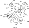
- a sleeve 220 similar to that shown in Figure 9 is provided to line the aperture 207 in the board 208. It has a lip 221 limiting its movement into the bore and external ribs 250 for engaging in the material of the board around the aperture.
- the lugs 2161 and then the abutments 2162 of the fixing device 201 engage in openings 222 extending from the lip part way along the sleeve.
- the arrangement provides enhanced torsional resistance to turning of the entire device when a fastener such as 130 is engaged in the bore 231 for making a fixture.
- the lugs and abutments finish flush with the front 2081 of the board when the fixing is made with the fingers engaging the back of the board. This is shown in Figure 25 .
- the assembly of the fingers needs to be inserted further into the board and the sleeve. This is achieved with a mallet, as the lugs and abutments forced a few millimetres below the front face of the board.
- the openings 222 are provided with bottoms 2221 at a position to be engaged by the lugs 2161 for rotating of the fingers as described above.
- the lugs need project only a few millimetres into the board material, so that they do not provide significant resistance to insertion of the device with a mallet.
- the grooves 232 in the diametric faces 206 of the proximal portions of the fingers are more than likely to be aligned sufficiently for the point of a fastening screw such as 130 to be started in the grooves and led into the bore 231.
- a fastening screw such as 130
- the fingers will be close to, if not already, being fully in their abutting orientation.
- Driving the screw into the grooves 232 will complete this process.
- the article to be secured may still be lose on the screw.
- Final tightening of the screw will be against the abutment of the distal portions of the fixing device on the back of the board and will draw the article against the front of the board. For this thicker board, there will remain a gap inside the sleeve between the lugs 2161 and abutments 2162 and the article. This will not detract from the fixing of the article in place against the board.
Claims (18)
- Dispositif de fixation destiné à être utilisé avec une attache pour fixer un article à un panneau au niveau d'une ouverture en son sein, le dispositif de fixation comprenant :• une paire de doigts complémentaires (102,103), chaque doigt comportant :• une partie distale (104) conçue pour l'insertion à travers l'ouverture du panneau en même temps que ou de manière séquentielle avec la partie distale de l'autre des deux doigts et• une partie proximale (105) conçue pour l'insertion de la même manière en même temps ou de manière séquentielle et la rotation des parties proximales dans l'ouverture,• un ergot (1161) sur l'une et/ou l'autre des parties proximales, espacé de et faisant saillie dans la direction générale de la partie distale respective, pour engager l'avant du panneau lors de l'insertion initiale des parties proximales, avec une rotation lors de l'insertion ultérieure, grâce à quoi les parties distales viennent en butée contre l'arrière du panneau et• un réceptacle d'attache formé dans l'une ou les deux des parties proximales ou formé dans un élément distinct pouvant s'engager avec celles-ci,l'agencement étant tel que :• lors de l'insertion et de la rotation des doigts, une attache peut être reçue dans le réceptacle de l'attache et• lors du serrage de l'attache, les parties distales sont sollicitées en butée contre l'arrière du panneau et l'article fixe peut être tiré par l'attache contre l'avant du panneau.
- Dispositif de fixation selon la revendication 1, lesdits doigts étant formés pour une insertion séquentielle et comportant une symétrie de rotation autour du réceptacle de l'attache formé sous forme de rainures (232) dans des surfaces diamétrales en butée au niveau de leurs parties proximales, grâce à quoi un doigt peut être inséré pour une rotation induite par l'ergot suivi du second doigt passant le long du premier, les rainures s'alignant pour former le réceptacle de l'attache lors de la rotation des doigts pour que les parties distales viennent en butée contre l'arrière du panneau.
- Dispositif de fixation selon la revendication 1, lesdits doigts étant formés pour une insertion séquentielle avec• le second devant être inséré :• étant dédoublé avec deux parties de partie distale adaptées pour passer des deux côtés de la partie proximale du premier doigt inséré, et• comportant une toile entre les parties dédoublées au niveau de la partie proximale du second doigt devant être inséré et• le premier doigt devant être inséré comportant un évidement au niveau de sa partie proximale dimensionné pour être mis en butée par la toile du second doigt devant être inséré.
- Dispositif de fixation selon la revendication 1, lesdits doigts étant formés pour une insertion séquentielle, la partie distale du second doigt devant être inséré étant dimensionnée pour passer à travers une ouverture dans la partie proximale du premier doigt devant être inséré.
- Dispositif de fixation selon la revendication 4, ledit premier doigt inséré comportant au niveau de sa partie proximale un élément de réceptacle d'attache, ou une partie réceptacle d'attache intégrale, agencé pour s'appuyer sur la partie proximale du second doigt inséré.
- Dispositif de fixation selon la revendication 4 ou la revendication 5 lorsqu'elle dépend de la revendication 1, ledit doigt comportant ledit ergot comportant un point d'appui pour la partie distale de l'autre doigt en vue de la rotation de son doigt pour venir en butée contre l'arrière du panneau.
- Dispositif de fixation selon l'une quelconque des revendications 3 à 6, ledit premier doigt inséré comportant au niveau de sa partie proximale un élément fournissant le réceptacle de l'attache, ou une partie réceptacle de fixation intégrale, agencé pour s'appuyer sur la partie proximale du second doigt inséré.
- Dispositif de fixation selon la revendication 1, chaque doigt comportant au niveau de sa partie proximale une partie conformée de pivotement (121,122) définissant un axe de pivotement autour duquel les doigts peuvent tourner lorsque, avant l'insertion, ils sont engagés ensemble pour être utilisés.
- Dispositif de fixation selon la revendication 8, (i) lesdites parties conformées de pivotement des deux doigts étant identiques et un élément distinct, assemblé, comportant le réceptacle de l'attache, étant fourni et comportant des parties conformées de pivotement complémentaires, ou (ii) lesdites parties conformées de pivotement des doigts comprenant une partie réceptacle d'attache, comportant un alésage transversal destiné à recevoir la fixation, et un axe de pivotement intégré à l'un des doigts et une partie conformée complémentaire de l'autre doigt.
- Dispositif de fixation selon la revendication 9, ladite partie réceptacle de l'attache s'étendant à partir d'une surface diamétrale centrale dudit un doigt, laquelle surface étant complémentaire à une surface similaire dans ledit autre doigt, les surfaces diamétrales comportant des rainures alignées avec le réceptacle de l'attache lorsque les doigts se trouvent au niveau de leur angle mutuel d'engagement de l'arrière du panneau, grâce à quoi les rainures prolongent le réceptacle de l'attache.
- Dispositif de fixation selon la revendication 10 ou la revendication 11, ledit axe de pivotement comportant une tête transversale et ladite partie conformée complémentaire comportant une fente pour que la tête transversale passe à travers suivant un angle des doigts différent de leur angle mutuel d'insertion et de leur angle mutuel d'engagement de l'arrière du panneau.
- Dispositif de fixation selon l'une quelconque des revendications précédentes, chaque doigt comprenant un point d'appui s'étendant à l'opposé de son ergot dans le prolongement de la direction de sa partie distale, l'agencement étant tel que lors du serrage de l'attache, celle-ci ou un article qu'elle maintient vient en butée contre les points d'appui provoquant la poussée des doigts vers la face arrière du panneau.
- Dispositif de fixation selon la revendication 12, lesdits points d'appui comprenant des méplats mis en butée par l'attache ou l'article attaché.
- Dispositif de fixation selon l'une quelconque des revendications précédentes, lesdits ergots et lesdits points d'appui lorsqu'ils sont pourvus étant ou comprenant des éléments angulaires destinés à entailler le panneau lors de l'utilisation.
- Dispositif de fixation selon l'une quelconque des revendications précédentes, comprenant un manchon (20) dimensionné pour que les parties distales traversent et reçoivent les parties proximales insérées, le manchon comportant :• une ou plusieurs ouvertures s'étendant depuis une extrémité du manchon pour recevoir ledit ou chaque ergot et• une ou plusieurs butées respectives dans les ouvertures, espacées de l'extrémité du manchon,l'agencement étant tel que :• pour un panneau relativement mince, le serrage de l'attache tire les parties distales contre l'arrière du panneau et le ou les ergots et les points d'appui lorsqu'ils sont pourvus contre l'avant du panneau, sans que ledit ou chaque ergot reçu dans une ouverture respective n'entre en contact avec une butée respective et• pour un panneau relativement épais, comportant une épaisseur supérieure à la partie distale pour l'écartement des ergots, ledit ou chaque ergot peut être plaqué en dessous de l'avant du panneau et contre une ou des butées respectives dans les ouvertures pour tirer les parties distales contre l'arrière du panneau.
- Dispositif de fixation selon la revendication 15, ledit manchon comportant un rebord destiné à venir en butée contre la face avant du panneau et/ou des nervures externes destinées à engager le panneau dans l'ouverture.
- Dispositif de fixation selon la revendication 1,lesdits doigts pouvant être verrouillés en contre-rotation en introduisant un trou dans chaque doigt qui loge un moyeu cylindrique fileté partagé qui permet à deux doigts ou plus d'être attachés au moyeu opposés l'un à l' autre lorsqu'ils sont insérés dans un trou préfabriqué qui permet à la fixation et aux doigts d'être insérés en même temps dans le trou préfabriqué et permet aux doigts de tourner en rotation opposée, oul'un des doigts pouvant avoir le moyeu rendu solidaire de lui-même en alignant les canaux semi-circulaires sur un trou fileté ou une ouverture en forme d'étoile à l'intérieur du moyeu, ou lesdits doigts incorporant des demi-canaux semi-circulaires qui permettent de verrouiller le mouvement de rotation des doigts l'un par rapport à l'autre et par rapport au moyeu central dans un état déployé une fois qu'une vis ou un boulon fileté est utilisé pour fixer un article où les canaux semi-circulaires ont le même rayon que la vis ou le boulon de fixation, oulesdits doigts pouvant comporter une section partiellement creuse d'un doigt permettant au second doigt légèrement plus petit de se déplacer de manière séquentielle à l'intérieur du premier doigt dans un sens de contre-rotation et d'être verrouillés ensemble mécaniquement, oulesdits doigts comportant un seul doigt central fileté qui permet à deux doigts externes reliés ensemble d'être introduits dans le trou dans un sens de contre-rotation et verrouillés ensemble avec un boulon ou une vis.
- Dispositif de fixation selon la revendication 1, comprenant un revêtement de manchon de tuyau supplémentaire facultatif avec une lèvre pour empêcher le revêtement du manchon de se déplacer à travers le trou préfabriqué dans le panneau de plâtre qui loge le dispositif de fixation améliorant la répartition latérale uniforme de la charge dans le trou à partir de la fixation.
Applications Claiming Priority (3)
| Application Number | Priority Date | Filing Date | Title |
|---|---|---|---|
| GB1915976.3A GB2588681A (en) | 2019-11-04 | 2019-11-04 | Plasterboard fixing device |
| GBGB2013127.2A GB202013127D0 (en) | 2020-08-21 | 2020-08-21 | Fixing device |
| PCT/GB2020/052771 WO2021089991A1 (fr) | 2019-11-04 | 2020-11-02 | Dispositif de fixation |
Publications (3)
| Publication Number | Publication Date |
|---|---|
| EP4055284A1 EP4055284A1 (fr) | 2022-09-14 |
| EP4055284B1 true EP4055284B1 (fr) | 2023-09-06 |
| EP4055284C0 EP4055284C0 (fr) | 2023-09-06 |
Family
ID=73646353
Family Applications (1)
| Application Number | Title | Priority Date | Filing Date |
|---|---|---|---|
| EP20816569.6A Active EP4055284B1 (fr) | 2019-11-04 | 2020-11-02 | Dispositif de fixation |
Country Status (9)
| Country | Link |
|---|---|
| US (1) | US20220381279A1 (fr) |
| EP (1) | EP4055284B1 (fr) |
| CN (1) | CN114829790A (fr) |
| AU (1) | AU2020377529A1 (fr) |
| CA (1) | CA3158005A1 (fr) |
| ES (1) | ES2964328T3 (fr) |
| MX (1) | MX2022005246A (fr) |
| PL (1) | PL4055284T3 (fr) |
| WO (1) | WO2021089991A1 (fr) |
Families Citing this family (1)
| Publication number | Priority date | Publication date | Assignee | Title |
|---|---|---|---|---|
| GB2618115A (en) * | 2022-04-27 | 2023-11-01 | Donovan Rule James | Hollow structure anchor |
Family Cites Families (22)
| Publication number | Priority date | Publication date | Assignee | Title |
|---|---|---|---|---|
| US507115A (en) * | 1893-10-24 | friedrichs | ||
| US532187A (en) * | 1895-01-08 | Nathan rubenstein | ||
| US736636A (en) * | 1903-01-20 | 1903-08-18 | Charles Henry Schill | Water-gas generator. |
| US767641A (en) * | 1904-02-01 | 1904-08-16 | Thomas Dudley Gayle | Saw-holder. |
| US1504147A (en) * | 1922-03-04 | 1924-08-05 | Fuller Brush Co | Faucet reducer |
| GB212370A (en) * | 1923-02-01 | 1924-03-13 | George Henry Tonks | An improved device or apparatus for fastening plates such as those employed in a gasometer, boiler, ship and other constructions and which is applicable for uniting various objects |
| US2013503A (en) * | 1934-12-26 | 1935-09-03 | Henry W Pleister | Spring toggle bolt |
| US2248238A (en) * | 1939-10-07 | 1941-07-08 | Harold A Hooper | Connector |
| US3651734A (en) * | 1969-04-23 | 1972-03-28 | Mechanical Plastics Corp | Expansible fastener |
| GB1319961A (en) * | 1969-12-03 | 1973-06-13 | Itw Ltd | Fasteners |
| US4065833A (en) * | 1976-07-06 | 1978-01-03 | Bender Lawrence C | Removable toggle link |
| US4878790A (en) * | 1985-04-02 | 1989-11-07 | Mechanical Plastics Corp. | Expansible fastening element |
| US4752170A (en) * | 1986-09-04 | 1988-06-21 | Mechanical Plastics Corp. | Fastening device with nesting anchoring elements |
| US5028186A (en) * | 1990-01-29 | 1991-07-02 | Mechanical Plastics Corp. | Hollow wall anchor with enhanced holding strength |
| US5252014A (en) * | 1992-12-09 | 1993-10-12 | Textron Inc. | Hole filling blind rivet |
| US5417531A (en) * | 1994-02-09 | 1995-05-23 | Brown; Gordon A. | Locking cam anchor apparatus |
| US6004088A (en) | 1999-01-11 | 1999-12-21 | Hunt; James W. | Wall fastener |
| DE10026886A1 (de) * | 2000-05-30 | 2001-12-06 | Fischer Artur Werke Gmbh | Spreizanker zur Befestigung an einem plattenförmigen Baustoff |
| JP3947698B2 (ja) * | 2002-09-25 | 2007-07-25 | ポップリベット・ファスナー株式会社 | スペーサクリップ |
| US8764364B2 (en) * | 2004-03-24 | 2014-07-01 | Illinois Tool Works Inc. | System and methods for wall and ceiling fastening |
| JP5176211B2 (ja) * | 2008-12-25 | 2013-04-03 | ポップリベット・ファスナー株式会社 | スペーサクリップ |
| US20140154028A1 (en) * | 2011-08-02 | 2014-06-05 | Chunguang Pei | Scisssors type expansion bolt |
-
2020
- 2020-11-02 WO PCT/GB2020/052771 patent/WO2021089991A1/fr unknown
- 2020-11-02 EP EP20816569.6A patent/EP4055284B1/fr active Active
- 2020-11-02 ES ES20816569T patent/ES2964328T3/es active Active
- 2020-11-02 CN CN202080076937.0A patent/CN114829790A/zh active Pending
- 2020-11-02 AU AU2020377529A patent/AU2020377529A1/en active Pending
- 2020-11-02 CA CA3158005A patent/CA3158005A1/fr active Pending
- 2020-11-02 PL PL20816569.6T patent/PL4055284T3/pl unknown
- 2020-11-02 US US17/755,615 patent/US20220381279A1/en active Pending
- 2020-11-02 MX MX2022005246A patent/MX2022005246A/es unknown
Also Published As
| Publication number | Publication date |
|---|---|
| EP4055284A1 (fr) | 2022-09-14 |
| MX2022005246A (es) | 2022-06-08 |
| ES2964328T3 (es) | 2024-04-05 |
| WO2021089991A1 (fr) | 2021-05-14 |
| CN114829790A (zh) | 2022-07-29 |
| PL4055284T3 (pl) | 2023-11-27 |
| US20220381279A1 (en) | 2022-12-01 |
| AU2020377529A1 (en) | 2022-04-14 |
| CA3158005A1 (fr) | 2021-05-14 |
| EP4055284C0 (fr) | 2023-09-06 |
Similar Documents
| Publication | Publication Date | Title |
|---|---|---|
| US5468109A (en) | Quick removable fasteners in particular for furniture | |
| US20200149571A1 (en) | Connecting device and method for connecting two components | |
| US7223045B2 (en) | Device and method for detachably connecting abutting structural parts and tie member for use to form said device | |
| JP3329832B2 (ja) | ねじ込み要素 | |
| US4131376A (en) | Fitting for detachable connecting structural parts | |
| US9644658B2 (en) | Extensible fixing device | |
| EP4055284B1 (fr) | Dispositif de fixation | |
| JP4339932B2 (ja) | 接合部形成装置 | |
| US20110271635A1 (en) | Wall anchor system | |
| WO2017203335A1 (fr) | Dispositif pour l'installation murale d'un article d'ameublement sanitaire, et procédé pour l'installation murale dudit article sanitaire | |
| US7517182B2 (en) | Screw anchor | |
| US8714863B2 (en) | Fasteners | |
| JPH0132369B2 (fr) | ||
| KR20170003058A (ko) | 결합이 용이한 가구조립용 체결구 | |
| US4080081A (en) | Method of joining a rattan pole to a member | |
| US6186695B1 (en) | Dowels for securing objects to walls | |
| US4402116A (en) | Concealed interlocking fastener | |
| KR102419254B1 (ko) | 건축용 앵커 | |
| GB2588681A (en) | Plasterboard fixing device | |
| US10655751B2 (en) | Hose bib handle replacement system | |
| GB1561985A (en) | Grommets for furniture connectors | |
| EP3622185B1 (fr) | Dispositif de fixation | |
| CA1153917A (fr) | Dispositif d'assemblage pour mur creux p.r. | |
| GB2587781A (en) | Tool | |
| AU2020286179A1 (en) | An anchor system |
Legal Events
| Date | Code | Title | Description |
|---|---|---|---|
| STAA | Information on the status of an ep patent application or granted ep patent |
Free format text: STATUS: UNKNOWN |
|
| STAA | Information on the status of an ep patent application or granted ep patent |
Free format text: STATUS: THE INTERNATIONAL PUBLICATION HAS BEEN MADE |
|
| PUAI | Public reference made under article 153(3) epc to a published international application that has entered the european phase |
Free format text: ORIGINAL CODE: 0009012 |
|
| STAA | Information on the status of an ep patent application or granted ep patent |
Free format text: STATUS: REQUEST FOR EXAMINATION WAS MADE |
|
| 17P | Request for examination filed |
Effective date: 20220516 |
|
| AK | Designated contracting states |
Kind code of ref document: A1 Designated state(s): AL AT BE BG CH CY CZ DE DK EE ES FI FR GB GR HR HU IE IS IT LI LT LU LV MC MK MT NL NO PL PT RO RS SE SI SK SM TR |
|
| DAV | Request for validation of the european patent (deleted) | ||
| DAX | Request for extension of the european patent (deleted) | ||
| GRAP | Despatch of communication of intention to grant a patent |
Free format text: ORIGINAL CODE: EPIDOSNIGR1 |
|
| STAA | Information on the status of an ep patent application or granted ep patent |
Free format text: STATUS: GRANT OF PATENT IS INTENDED |
|
| INTG | Intention to grant announced |
Effective date: 20230620 |
|
| GRAS | Grant fee paid |
Free format text: ORIGINAL CODE: EPIDOSNIGR3 |
|
| GRAA | (expected) grant |
Free format text: ORIGINAL CODE: 0009210 |
|
| STAA | Information on the status of an ep patent application or granted ep patent |
Free format text: STATUS: THE PATENT HAS BEEN GRANTED |
|
| AK | Designated contracting states |
Kind code of ref document: B1 Designated state(s): AL AT BE BG CH CY CZ DE DK EE ES FI FR GB GR HR HU IE IS IT LI LT LU LV MC MK MT NL NO PL PT RO RS SE SI SK SM TR |
|
| REG | Reference to a national code |
Ref country code: GB Ref legal event code: FG4D |
|
| REG | Reference to a national code |
Ref country code: CH Ref legal event code: EP |
|
| REG | Reference to a national code |
Ref country code: DE Ref legal event code: R096 Ref document number: 602020017400 Country of ref document: DE |
|
| REG | Reference to a national code |
Ref country code: IE Ref legal event code: FG4D |
|
| U01 | Request for unitary effect filed |
Effective date: 20230908 |
|
| U07 | Unitary effect registered |
Designated state(s): AT BE BG DE DK EE FI FR IT LT LU LV MT NL PT SE SI Effective date: 20230915 |
|
| U20 | Renewal fee paid [unitary effect] |
Year of fee payment: 4 Effective date: 20230920 |
|
| PG25 | Lapsed in a contracting state [announced via postgrant information from national office to epo] |
Ref country code: GR Free format text: LAPSE BECAUSE OF FAILURE TO SUBMIT A TRANSLATION OF THE DESCRIPTION OR TO PAY THE FEE WITHIN THE PRESCRIBED TIME-LIMIT Effective date: 20231207 |
|
| PGFP | Annual fee paid to national office [announced via postgrant information from national office to epo] |
Ref country code: ES Payment date: 20231208 Year of fee payment: 4 |
|
| PG25 | Lapsed in a contracting state [announced via postgrant information from national office to epo] |
Ref country code: RS Free format text: LAPSE BECAUSE OF FAILURE TO SUBMIT A TRANSLATION OF THE DESCRIPTION OR TO PAY THE FEE WITHIN THE PRESCRIBED TIME-LIMIT Effective date: 20230906 Ref country code: NO Free format text: LAPSE BECAUSE OF FAILURE TO SUBMIT A TRANSLATION OF THE DESCRIPTION OR TO PAY THE FEE WITHIN THE PRESCRIBED TIME-LIMIT Effective date: 20231206 Ref country code: HR Free format text: LAPSE BECAUSE OF FAILURE TO SUBMIT A TRANSLATION OF THE DESCRIPTION OR TO PAY THE FEE WITHIN THE PRESCRIBED TIME-LIMIT Effective date: 20230906 Ref country code: GR Free format text: LAPSE BECAUSE OF FAILURE TO SUBMIT A TRANSLATION OF THE DESCRIPTION OR TO PAY THE FEE WITHIN THE PRESCRIBED TIME-LIMIT Effective date: 20231207 |
|
| PGFP | Annual fee paid to national office [announced via postgrant information from national office to epo] |
Ref country code: PL Payment date: 20230920 Year of fee payment: 4 |
|
| REG | Reference to a national code |
Ref country code: ES Ref legal event code: FG2A Ref document number: 2964328 Country of ref document: ES Kind code of ref document: T3 Effective date: 20240405 |
|
| PG25 | Lapsed in a contracting state [announced via postgrant information from national office to epo] |
Ref country code: IS Free format text: LAPSE BECAUSE OF FAILURE TO SUBMIT A TRANSLATION OF THE DESCRIPTION OR TO PAY THE FEE WITHIN THE PRESCRIBED TIME-LIMIT Effective date: 20240106 |
|
| PG25 | Lapsed in a contracting state [announced via postgrant information from national office to epo] |
Ref country code: SM Free format text: LAPSE BECAUSE OF FAILURE TO SUBMIT A TRANSLATION OF THE DESCRIPTION OR TO PAY THE FEE WITHIN THE PRESCRIBED TIME-LIMIT Effective date: 20230906 Ref country code: RO Free format text: LAPSE BECAUSE OF FAILURE TO SUBMIT A TRANSLATION OF THE DESCRIPTION OR TO PAY THE FEE WITHIN THE PRESCRIBED TIME-LIMIT Effective date: 20230906 Ref country code: IS Free format text: LAPSE BECAUSE OF FAILURE TO SUBMIT A TRANSLATION OF THE DESCRIPTION OR TO PAY THE FEE WITHIN THE PRESCRIBED TIME-LIMIT Effective date: 20240106 Ref country code: CZ Free format text: LAPSE BECAUSE OF FAILURE TO SUBMIT A TRANSLATION OF THE DESCRIPTION OR TO PAY THE FEE WITHIN THE PRESCRIBED TIME-LIMIT Effective date: 20230906 Ref country code: SK Free format text: LAPSE BECAUSE OF FAILURE TO SUBMIT A TRANSLATION OF THE DESCRIPTION OR TO PAY THE FEE WITHIN THE PRESCRIBED TIME-LIMIT Effective date: 20230906 |