EP4054411B1 - Analyse von ausgeatmetem gas - Google Patents
Analyse von ausgeatmetem gas Download PDFInfo
- Publication number
- EP4054411B1 EP4054411B1 EP20796787.8A EP20796787A EP4054411B1 EP 4054411 B1 EP4054411 B1 EP 4054411B1 EP 20796787 A EP20796787 A EP 20796787A EP 4054411 B1 EP4054411 B1 EP 4054411B1
- Authority
- EP
- European Patent Office
- Prior art keywords
- sealed housing
- electrode
- housing
- interior
- exhaled
- Prior art date
- Legal status (The legal status is an assumption and is not a legal conclusion. Google has not performed a legal analysis and makes no representation as to the accuracy of the status listed.)
- Active
Links
Images


Classifications
-
- A—HUMAN NECESSITIES
- A61—MEDICAL OR VETERINARY SCIENCE; HYGIENE
- A61B—DIAGNOSIS; SURGERY; IDENTIFICATION
- A61B5/00—Measuring for diagnostic purposes; Identification of persons
- A61B5/08—Measuring devices for evaluating the respiratory organs
- A61B5/082—Evaluation by breath analysis, e.g. determination of the chemical composition of exhaled breath
-
- A—HUMAN NECESSITIES
- A61—MEDICAL OR VETERINARY SCIENCE; HYGIENE
- A61B—DIAGNOSIS; SURGERY; IDENTIFICATION
- A61B5/00—Measuring for diagnostic purposes; Identification of persons
- A61B5/0059—Measuring for diagnostic purposes; Identification of persons using light, e.g. diagnosis by transillumination, diascopy, fluorescence
- A61B5/0075—Measuring for diagnostic purposes; Identification of persons using light, e.g. diagnosis by transillumination, diascopy, fluorescence by spectroscopy, i.e. measuring spectra, e.g. Raman spectroscopy, infrared absorption spectroscopy
-
- A—HUMAN NECESSITIES
- A61—MEDICAL OR VETERINARY SCIENCE; HYGIENE
- A61B—DIAGNOSIS; SURGERY; IDENTIFICATION
- A61B5/00—Measuring for diagnostic purposes; Identification of persons
- A61B5/08—Measuring devices for evaluating the respiratory organs
- A61B5/087—Measuring breath flow
- A61B5/0873—Measuring breath flow using optical means
-
- A—HUMAN NECESSITIES
- A61—MEDICAL OR VETERINARY SCIENCE; HYGIENE
- A61B—DIAGNOSIS; SURGERY; IDENTIFICATION
- A61B5/00—Measuring for diagnostic purposes; Identification of persons
- A61B5/72—Signal processing specially adapted for physiological signals or for diagnostic purposes
- A61B5/7225—Details of analogue processing, e.g. isolation amplifier, gain or sensitivity adjustment, filtering, baseline or drift compensation
-
- G—PHYSICS
- G01—MEASURING; TESTING
- G01N—INVESTIGATING OR ANALYSING MATERIALS BY DETERMINING THEIR CHEMICAL OR PHYSICAL PROPERTIES
- G01N21/00—Investigating or analysing materials by the use of optical means, i.e. using sub-millimetre waves, infrared, visible or ultraviolet light
- G01N21/17—Systems in which incident light is modified in accordance with the properties of the material investigated
- G01N21/25—Colour; Spectral properties, i.e. comparison of effect of material on the light at two or more different wavelengths or wavelength bands
- G01N21/31—Investigating relative effect of material at wavelengths characteristic of specific elements or molecules, e.g. atomic absorption spectrometry
-
- G—PHYSICS
- G01—MEASURING; TESTING
- G01N—INVESTIGATING OR ANALYSING MATERIALS BY DETERMINING THEIR CHEMICAL OR PHYSICAL PROPERTIES
- G01N21/00—Investigating or analysing materials by the use of optical means, i.e. using sub-millimetre waves, infrared, visible or ultraviolet light
- G01N21/62—Systems in which the material investigated is excited whereby it emits light or causes a change in wavelength of the incident light
- G01N21/66—Systems in which the material investigated is excited whereby it emits light or causes a change in wavelength of the incident light electrically excited, e.g. electroluminescence
- G01N21/67—Systems in which the material investigated is excited whereby it emits light or causes a change in wavelength of the incident light electrically excited, e.g. electroluminescence using electric arcs or discharges
-
- G—PHYSICS
- G01—MEASURING; TESTING
- G01N—INVESTIGATING OR ANALYSING MATERIALS BY DETERMINING THEIR CHEMICAL OR PHYSICAL PROPERTIES
- G01N33/00—Investigating or analysing materials by specific methods not covered by groups G01N1/00 - G01N31/00
- G01N33/48—Biological material, e.g. blood, urine; Haemocytometers
- G01N33/483—Physical analysis of biological material
- G01N33/497—Physical analysis of biological material of gaseous biological material, e.g. breath
-
- A—HUMAN NECESSITIES
- A61—MEDICAL OR VETERINARY SCIENCE; HYGIENE
- A61B—DIAGNOSIS; SURGERY; IDENTIFICATION
- A61B2560/00—Constructional details of operational features of apparatus; Accessories for medical measuring apparatus
- A61B2560/02—Operational features
- A61B2560/029—Operational features adapted for auto-initiation
-
- A—HUMAN NECESSITIES
- A61—MEDICAL OR VETERINARY SCIENCE; HYGIENE
- A61B—DIAGNOSIS; SURGERY; IDENTIFICATION
- A61B2562/00—Details of sensors; Constructional details of sensor housings or probes; Accessories for sensors
- A61B2562/02—Details of sensors specially adapted for in-vivo measurements
- A61B2562/0247—Pressure sensors
-
- A—HUMAN NECESSITIES
- A61—MEDICAL OR VETERINARY SCIENCE; HYGIENE
- A61B—DIAGNOSIS; SURGERY; IDENTIFICATION
- A61B5/00—Measuring for diagnostic purposes; Identification of persons
- A61B5/08—Measuring devices for evaluating the respiratory organs
- A61B5/097—Devices for facilitating collection of breath or for directing breath into or through measuring devices
-
- G—PHYSICS
- G01—MEASURING; TESTING
- G01N—INVESTIGATING OR ANALYSING MATERIALS BY DETERMINING THEIR CHEMICAL OR PHYSICAL PROPERTIES
- G01N2201/00—Features of devices classified in G01N21/00
- G01N2201/02—Mechanical
- G01N2201/022—Casings
- G01N2201/0221—Portable; cableless; compact; hand-held
Definitions
- the invention relates to a spectral analysis of gases exhaled by a patient and, more particularly, to a universal portable breath content analyzer and a method of exhaled gas analysis based on the use of the aforementioned analyzer.
- Analysis of gases exhaled by a patient refers to non-invasive methods for diagnosing patients, which causes increased interest.
- gases in the exhalation of a patient may be associated with predetermined diseases.
- provision of acetone (C 3 H 6 O) in an exhale sample in an amount of 4 to 20 ppm may characterize a pancreas function at acute destructive pancreatitis, dietary imbalance, severe heart failure, or lung cancer.
- a presence of methanol (CH 3 OH) or ethanol (C 2 H 6 O) in an amount of > 500 ppm or acetaldehyde (CH 3 CHO) in an amount of 4 - 20 ppm may be associated with diseases of the central nervous system, sugar diabetes, or alcoholism, etc.
- GC gas chromatography
- MS-GC mass spectrometry combined with gas chromatographic separation
- SEC electrochemical sensors
- PS semiconductor sensors
- UVCL UV chemoluminescence
- IR IR spectroscopy
- breath content analyzers and methods of breath content analysis were developed, used in a medical diagnostic practice, and disclosed in the scientific and patent literature.
- a big group of such devices and methods relate to spectral analysis of gas samples exhaled by a patient.
- US Patent No. 7153272 issued on December 26, 2006 to Talton discloses methods of collecting and detecting compounds in a human breath sample.
- the method consists of the steps of exhaling into a handheld sample collector to absorb at least one breath compound in an exhaled breath collector, connecting the handheld sample collector to a breath analyzer, transferring the breath compounds from the exhaled breath collector into the breath analyzer, and detecting breath compounds using two or more sensors.
- the method may be performed to detect breath compounds for determining health or disease diagnosis, or for drug monitoring. detection may be performed using mass spectroscopy, or electronic, optical, or acoustic vapor sensors.
- Sensors may include at least one sensor selected from the group consisting of surface acoustic wave sensors, shear horizontal wave sensors, flexural plate wave sensors, quartz microbalance sensors, conducting polymer sensors, dye-impregnated polymer film on fiber optic detectors, conductive composite sensors, chemiresistors, metal oxide gas sensors, electrochemical gas detectors, chemically sensitive field-effect transistors, and carbon black-polymer composite devices.
- the sensors are removable and/or replaceable.
- a breath sample may comprise multiple breath compounds, including, but not limited to, alcohols, ethers, ketones, amines, aldehydes, carbonyls, carbanions, alkanes, alkenes, alkynes, aromatic hydrocarbons, polynuclear aromatics, biomolecules, sugars, isoprenes, isoprenoids, indoles, pyridines, fatty acids, and off-gases of a microorganism.
- breath compounds including, but not limited to, alcohols, ethers, ketones, amines, aldehydes, carbonyls, carbanions, alkanes, alkenes, alkynes, aromatic hydrocarbons, polynuclear aromatics, biomolecules, sugars, isoprenes, isoprenoids, indoles, pyridines, fatty acids, and off-gases of a microorganism.
- US Patent No. US 6955652 issued on October 18, 2005 to Baum, et al discloses a non-invasive, miniature, breath monitoring apparatus for spectroscopic multi-component breath monitoring and analysis.
- the system is comprised of one or more IR emitters focused by optical elements through a low volume sample cell receiving a sample input of a patient's breath for analysis.
- the patient either at rest or during exercise, inhales C 2 H 2 -SF 6 mixtures (balance of oxygen and nitrogen) which is subsequently monitored upon exhalation for CO 2 , H 2 O, C 2 H 2 , and SF 6 , which can be employed to determine Q (the amount of blood pumped by the heart per minute) directly and accurately. Measurements are performed in real-time or via post-processing of stored original data.
- the miniature analyzer operates on the principle of infrared absorption spectroscopy.
- US Patent No. S5095913 issued on March 17, 1992 to Yelderman, et al. discloses methods and apparatus for constructing optically stabilized, shutterless infrared capnographs.
- the capnographs provide absolute concentrations of the constituents of a patient's respiratory airstream without thermal drift problems normally associated with thermopile detectors, thereby providing a device with a high degree of accuracy.
- the present invention eliminates the need for a mechanical shutter to modulate the incident infrared beam and the need for a modulated source, thereby increasing the reliability and response time of the devices disclosed.
- Capnographs, which are substantially unaffected by changes in the ambient temperature at which they operate, are provided by connecting pairs of optically filtered thermopiles in series and processing the resulting differential pairs.
- US Patent No. 6469303 issued on October 22, 2002 to Sun, et al. discloses a non-dispersive infrared sensor that includes a cylindrical metallic tube, a printed circuit board platform that fits into one end of the tube, a diffusion filter that fits into the opposite end of the tube, and an optical system.
- the optical system includes an infrared source on the platform, a mirror on the inner wall of the tube so as to reflect and focus the infrared light from the infrared source, and a detector assembly that receives the infrared light after reflection.
- the gas sensor may further include a partition between the infrared source and the detector assembly, a removable filter on the diffusion filter, connecting pins attached to the platform, and a sealing layer formed under the platform.
- the detector assembly includes a signal detector and a reference detector. A first and second bandpass filters are respectively formed on the signal and reference detectors.
- US Patent Application Publication No. 20170146449 issued May 25, 2017 discloses a multi-component gas and vapor monitoring sensor device that contains a series of optical spectral sensors for gas and vapor measurements using a combination of solid-state light sources (LED or Broadband) and multi-element detectors, housed within an integrated package that includes the interfacing optics and acquisition and processing electronics. Spectral selectivity is provided by a custom detector eliminating the need for expensive spectral selection components.
- the multi-component gas monitor system has no moving parts, and a gas sample flows through a measurement chamber where it interacts with a light beam created from the light source, such as a MEMS broad band IR source or a matrix of LEDs.
- a custom detector(s) is/are configured with multi-wavelength detection to detect and measure the light beam as it passes through the sample within the measurement chamber.
- US Patent No. 5800360 issued on September 1, 1998 to Kisner, et al. discloses a passive, non-invasive, non-contacting apparatus and method for monitoring the respiration of a subject within a monitored environment.
- the apparatus generally comprises a pair of sensors, which detect changes in infrared energy.
- the first sensor detects changes in infrared energy, which signifies and corresponds to changes in the monitored environments of a component to be monitored and generates the first signal.
- the second sensor detects changes in infrared energy, which signifies reference infrared energy in the monitored environment and generates the second signal.
- a processing system converts the first and second signals into a third signal, which signifies the concentration of the monitored component in the monitored environment.
- the monitored components may be carbon dioxide (CO 2 ), water vapor (H 2 O) or a constituent of exhaled breath such as a ketone, amino acid, insulin or pintane.
- CO 2 carbon dioxide
- H 2 O water vapor
- a constituent of exhaled breath such as a ketone, amino acid, insulin or pintane.
- changes in blood pH may be monitored by adding an additional sensor.
- Micromotion of the subject's body may also be monitored in yet another embodiment through the use of a single sensor together with an appropriate processing system. Imaging techniques may be employed to accomplish high resolution monitoring of the monitored environment.
- US Patent No. 5747809 issued on May 5, 1998 to Eckstrom discloses an NDIR apparatus and method for measuring isotopic ratios in gaseous samples.
- the apparatus provides four separate optical paths for separate measurement of each of two isotopes relative to a reference signal, using spectrally resolved infrared radiation.
- the design permits the measurements to be made accurately without significant time lags between measurements, and without interchanging of cells or filters.
- Trace amounts of infrared active gases can be routinely detected by non-dispersive infrared spectroscopy.
- the filtered IR radiation passes through a gas sample, where it is absorbed in proportion to the amount of that species present, and falls on a detector, which measures the fraction of radiation transmitted.
- the radiation may be filtered after passing through the gas sample.
- An unattenuated reference signal may also be generated by including a filter, which restricts radiation to a range where no absorption occurs.
- the gas analyzer system includes: (1) a transducer for outputting a signal indicative of the concentration of a specified gas in a sample, which may contain that gas, and (2) an airway adapter or cuvette with a flow passage for confining the sample to a particular path traversing the transducer.
- the cuvettes feature radiant energy transmitting windows, which are flush mounted in apertures on opposite sides of the cuvette flow passage and are fabricated from a polymer such as biaxially oriented polypropylene which is malleable, yet resistant to wrinkling, warping, and other forms of distortion. Retainer rings keep the windows flat and distortion free with an accurately reproducible spacing between the windows.
- the mirror is intended for reflecting a dissipated energy of the luminescent light generated by a glow discharge, which is generated in the tubular housing under effect of the voltage applied to the interior of a pre-evacuated tubular housing.
- Generation of the discharge in a predetermined synchronization with the evacuation of air and apply of a voltage of predetermined level is performed under control of the CPU.
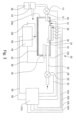
- the device which in an assembled state is designated by reference numeral 20, has a sealed tubular housing 22, which consists of a cylindrical body 24 and end-face wall 24a and 24b.
- a sealed tubular housing 22 which consists of a cylindrical body 24 and end-face wall 24a and 24b.
- an interior 24c of the sealed housing 22, which is defined by the outer wall, in this case the cylindrical body 24, the front end wall 24a, and the rear end face wall 24b, is connected to an air evacuation tube 26, which, in turn, is connected to a vacuum pump (not shown in Figs. 1 and 2 ) and through an electrode 28 that passes through the front wall 24a to a high-voltage source (not shown in Figs. 1 and 2 ).
- a respiratory sampling mouthpiece 30 through which a sample of an air exhaled from a patient is taken also passes into the interior 24c of the sealed tubular housing 22 through the front wall 24a.
- the counter electrode is a mirror that is located outside the outer housing and encompasses said at least a part of the outer wall, which is transparent.
- the entire sealed tubular housing 22 is made, e.g., from a purified fused silica or suprasil glass. From the outer side, the sealed tubular housing 22 is encompassed by a semi-cylindrical mirror 32 ( Fig. 2 ).
- Fig. 3 is a schematic sectional view of the entire system of the device 20 of the invention that illustrates interconnection of the device 20 with components of the control system.
- the mirror 32 is used as a counter electrode relative to the electrode 28 located on the high-voltage source side.
- the tubular housing 22 On the side opposite to the mirror 32, the tubular housing 22 has an opening 36. Inserted into the opening 36 is a flat transparent glass plate 37 made from the same material as the tubular housing 22.
- the glass plate 36 supports a set of replaceable optical filter/waveband sensor assemblies, hereinafter referred to as replaceable optical filter assemblies 38, which contains a number of flat optical bandpass filters 40a, 40b, 40c, and 40d that are shown in Fig. 4 , which is an exploded three-dimensional view of the replaceable optical waveband filter assembly 38.
- Replaceable optical filter assemblies 38 which contains a number of flat optical bandpass filters 40a, 40b, 40c, and 40d that are shown in Fig. 4 , which is an exploded three-dimensional view of the replaceable optical waveband filter assembly 38.
- Four optical waveband filters are shown only as an example and the number of the optical filters may be different.
- each bandwidth filter is intended for filtering out lights of a predetermined bandwidth.
- the optical filter assembly 38 supports sensors 42a, 42b, 42c, and 42d, which are aligned with the respective optical bandwidth filters 40a, 40b, 40c, and 40d and intended for receiving optical signals from the respective filters and for converting these optical signals into electrical signals that correspond to the gas components contained in the respiratory gas sampled and analyzed by the device 20.
- the following sensors/photodiodes can be used for UV wavelengths GaP photodiodes (e.g. FGAP71 from Thorlabs), for visual and in the beginning of infrared range wavelengths Si photodiodes (e.g. FDS010 from Thorlabs), and for near-infrared wavelengths InGaAs photodiodes (e.g. FD10D from Thorlabs).
- GaP photodiodes e.g. FGAP71 from Thorlabs
- Si photodiodes e.g. FDS010 from Thorlabs
- InGaAs photodiodes e.g. FD10
- the optical sensors 42a, 42b, 42c, and 42d are parts of the optical filter assembly 38 and are replaceable together with the filters as an integral unit.
- the breath content analyzer 20 of the invention may contain a set of such replaceable filter assemblies 38 for covering different bandwidth ranges. Since in visible and near-infrared light spectra the light-emitting molecules present in a gas discharge show more than one line of illumination, the use of the aforementioned set of replaceable optical filter assemblies 38 makes it possible to expand an assortment of gas components to be identified and thus increase versatility of the breath content analyzer 20 of the invention.
- reference numerals 42a-1, 42a-2, 42b-1, 42b-2 ?? 42d-1, 42d-2 designate electrical terminals, from which the component-identifying electric signals of the sensors are sent to a central processing unit, hereinafter CPU 40, shown in Fig. 3 .
- the CPU 40 may be comprised of a personal computer, a tablet, or even a smart phone with a special software or App.
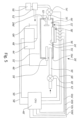
- an analyzer 20' contains some other important parts and components, which are shown in the modification of Fig. 5 .
- This modification which is not according to the invention, differs from those according to the invention shown in Figs. 1 to 4 in that a rod-like counter electrode 32' that passes into the interior 24 of the housing 22 through the rear wall 24b is used instead of the mirror 32.
- a rod-like counter electrode 32' that passes into the interior 24 of the housing 22 through the rear wall 24b is used instead of the mirror 32.
- those parts and assemblies that were described earlier will be designated by the same numeral references as in Figs. 1 to 4 but with addition of a prime (').
- the housing is designated by reference numeral 22'
- the electrode 28 is designated by reference numeral 28', etc.
- the analyzer 20' is also equipped with other important elements, which have not been described above. Among them is a high voltage power source 44', which is connected to the electrode 28' via a link 46'. It is understood that both electrodes have opposite polarities.
- Reference numeral 52' designates a vacuum pump, which evacuates air from the interior 24' of the sealed tubular housing 22' via a cut-off valve 54' of the air evacuation system. The cut-off valve 54' is connected to the CPU 40' via a link 55'. The vacuum pump 52' is controlled by a driver 56', which is connected to the CPU via a link 58'.
- a flow control valve 60' that ensures a metered gas flow into the vacuum system is installed on the inlet end of the respiratory sampling mouthpiece 30'.
- the valve 60' is also linked to the CPU 40' via a link 62'.
- the electrical terminals 42a-1, 42a-2, 42b-1, 42b-2 ?? 42d-1, 42d-2 of the respective sensors 42a, 42b, 42c, and 42c are linked to the CPU 40'.
- these links are designated by reference numerals 64a', 64b,' 64c', and 64d'.
- a pressure sensor 66 Installed in the interior 24 of the sealed tubular housing 22 is a pressure sensor 66, which is linked to the CPU via a link 68.
- a provision of the pressure sensor 66 for measuring the pressure of gas in the interior 24' of the housing 22' is a factor very important for realization of a method according to which at all measurements of the breath components the pressure is maintained at a constant level regardless of the expiratory volume produced by the patient. Accomplishment of this condition is absolutely necessary for obtaining quantitative data on the content of the sought components, which are necessary for the subsequent data analysis and diagnostics.
- a pressure that has to be maintained in the interior 24 is pre-assigned in the CPU 40.
- the valve 60 is shut off, and the air contained in the interior of the housing 22 is evacuated via the valve 54 by the vacuum pump 52.
- the valve 54 is shut off, the valve 60 is open, and the patient exhales a portion of air into the interior 24 of the housing 22 via the valve 60.
- the gas evacuation valve 54 remains closed, the pressure inside the housing is controlled by the pressure sensor 66, and when a given pressure at which all measurements are conducted is achieved the valve 60 is closed.
- a voltage of about 300V-5000V is then applied to the electrode 28, and a glow discharge 34 ( Fig. 2 ) is generated in the interior 24 of the tubular housing between the electrodes, i.e., the mirror 32 and the electrode 28.
- Conditions for generation of the glow discharge in the analyzer of a specific geometry are provided by precondition data inputted to the CPU with reference to the specific dimensions, inter-electrode distance, level of vacuum in the interior 24 of the housing 22, type of the gas, etc.
- tubular housing 22 Since the tubular housing 22 is transparent, the portion of light incident onto the mirror 32 is reflected back to the glow discharge whereby the signal of the luminescent light of glow discharge is intensified.
- the light passes to sensors 42a, 42b, 42c, and 42d that convert the optical signals into electric signals, which are then sent to the CPU from their terminals 42a-1, 42a-2, 42b-1, 42b-2, 42c-1, 42c-2, 42d-1, and 42d-2 via respective lines 64a, 64b, 64c, and 64d.
- both valves 60 and 54 are opened, and the interior 24 of the cylindrical housing 22 is scavenged by evacuating the exhaled air probe from the housing for the preparation of the device to the next breath analysis cycle.
- the analyzer 20' of the second modification shown in Fig.5 which is not according to the invention, works in the same manner as the analyzer 20 except that a metal counter electrode 32' is used instead of a mirror-type electrode 32 of the previous modification.
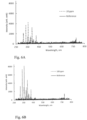
- Fig. 6A and 6B are examples of spectra obtained with the use of a spectrometer in samples of an exhaled gas associated with a glow discharge, wherein Fig. 6A is for 20 ppm concentration of acetone in the exhaled test probe, and Fig. 6B for 100 ppm concentration of acetone in the exhaled test probe.
- main parameters of the optical bandpass filters 40a, 40b, 40c, and 40d are bands of transparency for respective lines of luminescence. Each filter passes only one line of predetermined wavelength. Such an approach makes it possible to reveal and identify specific gas components present in the gas mixture, in this case, an exhaled gas sample.
- the search for components other than those associated with an appropriate group of filters will require replacement of the present kit of filter-sensor assemblies 38 ( Fig. 1 and Fig. 3 ).
- the analyzer 20 of the invention contains a set of such replaceable filter assemblies for covering different bandwidth ranges.
- dependence of the intensity of luminescence from concentration of the sought gas component makes it possible to evaluate the presence of this component quantitatively.
- the analyzer 20 (20') may operate in different modes. Let us consider as an example the operation of the analyzer system, which is not in accordance with the invention, shown in Fig. 5 .
- the valve 54' is open, and air is evacuated from the interior of the housing 22' by activating the pump 52'.
- the pressure inside the housing 22' is controlled by the CPU 40' via the pressure sensor 66'.
- valve 54' When a predetermined pressure optimal from the viewpoint of obtaining the most reliable measurement results is achieved, the valve 54' is shut off, the mouthpiece 30' is inserted into the patient's mouth (not shown), the flow control valve 60' is opened, a sample of an exhaled air is admitted into the housing 22', and when the pressure in the housing reaches a predetermined value, the valve 60' is shut off. Simultaneously with shutting off the valve 60', a high voltage is applied to the electrode 28' from the high-voltage power source 44'. As a result, a glow discharge 34 of the type shown in Fig. 2 is generated inside the housing 22' between the electrode 28' and the counter electrode 24'.
- the light of the discharge is transmitted through the glass plate 36' and the filters 40a, 40b, 40c, and 40d to the respective sensors 42a', 42b', 42c' , and 42d'.
- the sensors 42a', 42b', 42c, and 42d' which receive the discharge emission light that passed through the corresponding filters generate electrical signals the amplitudes of which are proportional to the concentration of the sought components. These signals are transmitted via the respective links 64a', 64b', 64c', and 64d' to the CPU' 40, where the obtained data are analyzed.
- the method consists of providing an exhaled gas analysis device 20 (20') of the type described above.
- Next step is closing the flow control valve 60', opening the shut off valve 54', evacuating air from the sealed housing 22', closing the shut off valve 54' upon completion of air evacuation, opening the flow control valve 60', admitting an air inhaled from a patient into the sealed housing 22' while measuring the pressure inside the sealed housing 22', closing the flow control valve 60' when the pressure measured by the pressure sensor 66' reaches a value of the given constant value, generating a discharge in the sealed housing 22', passing a light produced by the discharge through optical filters 40a, 40b, 40c, and 40d ( Fig.
- the analyzer of the present invention has the following essential distinctions from conventional devices of this class:
- a glow discharge can be used for activation of the emission from the sought components.
- Sensors may be comprise a system of bandwidth filters applied one onto the other.
Landscapes
- Health & Medical Sciences (AREA)
- Life Sciences & Earth Sciences (AREA)
- Physics & Mathematics (AREA)
- Engineering & Computer Science (AREA)
- General Health & Medical Sciences (AREA)
- Molecular Biology (AREA)
- Biomedical Technology (AREA)
- Pathology (AREA)
- Biophysics (AREA)
- Public Health (AREA)
- Surgery (AREA)
- Veterinary Medicine (AREA)
- Heart & Thoracic Surgery (AREA)
- Medical Informatics (AREA)
- Animal Behavior & Ethology (AREA)
- Chemical & Material Sciences (AREA)
- Spectroscopy & Molecular Physics (AREA)
- Physiology (AREA)
- Analytical Chemistry (AREA)
- Immunology (AREA)
- General Physics & Mathematics (AREA)
- Biochemistry (AREA)
- Pulmonology (AREA)
- Signal Processing (AREA)
- Medicinal Chemistry (AREA)
- Hematology (AREA)
- Urology & Nephrology (AREA)
- Food Science & Technology (AREA)
- Artificial Intelligence (AREA)
- Psychiatry (AREA)
- Computer Vision & Pattern Recognition (AREA)
- Power Engineering (AREA)
- Nuclear Medicine, Radiotherapy & Molecular Imaging (AREA)
- Investigating Or Analysing Biological Materials (AREA)
- Sampling And Sample Adjustment (AREA)
- Investigating Or Analysing Materials By Optical Means (AREA)
Claims (11)
- Universeller tragbarer Ateminhaltsanalysator (20), umfassend:ein abgedichtetes Gehäuse (22), das eine Außenwand, eine erste Endflächenwand (24a) und eine zweite Endflächenwand (24b), die sich gegenüber von der ersten Endflächenwand befindet, aufweist, wobei das abgedichtete Gehäuse (22) einen Innenraum aufweist, der durch die Außenwand, die erste Endfläche und die zweite Endfläche definiert ist;eine erste Elektrode (28), die in den Innenraum des abgedichteten Gehäuses (22) durch eine der Endflächen übergeht;eine Spannungsversorgungsquelle, die mit der ersten Elektrode (28) zum Anlegen einer Spannung an die erste Elektrode verbunden ist;eine Gegenelektrode (32) für eine Wechselwirkung mit der ersten Elektrode (28) und zum Generieren einer Entladung in dem Innenraum des abgedichteten Gehäuses (22), wenn eine Spannung, die zum Generieren einer Entladung zwischen der ersten Elektrode (28) und der zweiten Elektrode (32) ausreicht, an die erste Elektrode angelegt wird;ein Mundstück (30) zum Entnehmen einer Probe von ausgeatmeter Luft von einem Patienten und zum Zuführen der ausgeatmeten Luft in den Innenraum des abgedichteten Gehäuses (22);ein Durchflussregelventil (60), das in dem Mundstück (30) installiert ist, um das Mundstück (30) offen oder geschlossen zu halten;ein Luftableitungsröhrchen (26), das in den Innenraum des abgedichteten Gehäuses (22) eingesetzt ist;eine Vakuumpumpe (52) mit einem Antrieb (56), der mit dem Luftableitungsröhrchen (26) verbunden ist;ein Absperrventil (54), das in dem Luftableitungsröhrchen (26) zwischen dem Innenraum des abgedichteten Gehäuses (22) und der Vakuumpumpe (52) installiert ist;einen Drucksensor (66), der sich im Inneren des Innenraums des abgedichteten Gehäuses (22) zum Messen von Druck in dem Innenraum befindet;eine Öffnung (36) in der Außenwand;eine transparente Platte (37), die in der Öffnung (36) installiert ist;einen Satz auswechselbarer optischer Filter/Wellenbandsensor-Baugruppen (38), die auf der transparenten Platte (37) entfernbar installierbar sind, jede auswechselbare optische Filter/Wellenbandfilter-Baugruppe umfassend einen Wellenbandfilter zum Durchlassen von Licht der Entladung mit einem vorbestimmten Wellenband und einen Sensor, der in der Lage ist, optische Signale der Entladung in elektrische Signale umzuwandeln; undeine zentrale Verarbeitungseinheit (40), die mit dem Durchflussregelventil, dem Absperrventil, der Spannungsversorgungsquelle, dem Antrieb (56) der Vakuumpumpe (52) und dem Drucksensor (66) jeder austauschbaren optischen Filter-/Wellenbandfilter-Baugruppe verbunden ist, zum Regeln des Betriebs der vorgenannten Vorrichtungen in Abhängigkeit von dem Druck, der durch den Drucksensor (66) gemessen wird,wobei das Gehäuse (22) ein zylindrischer Körper ist, mindestens ein Teil der Außenwand transparent ist und die Gegenelektrode (32) ein halbzylindrischer Spiegel ist, der sich außerhalb des Außengehäuses (22) befindet und mindestens den einen Teil der Außenwand umgibt, der transparent ist.
- Universeller tragbarer Ateminhaltsanalysator (20) nach Anspruch 1, wobei die CPU aus der Gruppe ausgewählt ist, bestehend aus einem Personalcomputer, einem Tablet und einem Smartphone.
- Universeller tragbarer Ateminhaltsanalysator (20) nach Anspruch 1, wobei die CPU aus der Gruppe ausgewählt ist, bestehend aus einem Personalcomputer, einem Tablet und einem Smartphone.
- Verfahren für die Analyse von ausgeatmetem Gas, das unter konstantem Druck vorgenommen wird, umfassend:a) Bereitstellen einer Vorrichtung für die Analyse von ausgeatmetem Gas, umfassend ein abgedichtetes Gehäuse (22), einen Drucksensor (66) zum Messen des Drucks in dem abgedichteten Gehäuse (22), ein Durchflussregelventil (60) zum Regeln des Einlasses von ausgeatmeter Luft eines Patienten in das abgedichtete Gehäuse (22), ein Absperrventil, das mit einer Vakuumpumpe (52) für die Ableitung von Luft aus dem abgedichteten Gehäuse (22) verbunden ist, wobei das abgedichtete Gehäuse (22) eine Außenwand, eine erste Endflächenwand (24a) und zweite Endflächenwand (24b), die sich gegenüber von der ersten Endfläche befindet, aufweist, wobei das abgedichtete Gehäuse (22) einen Innenraum, der durch die Außenwand, die erste Endfläche und die zweite Endfläche definiert ist, eine erste Elektrode (28), die in den Innenraum des abgedichteten Gehäuses (22) durch eine der Endflächen übergeht, und eine Gegenelektrode (32) für die Wechselwirkung mit der ersten Elektrode (28) und zum Generieren einer Entladung in dem Innenraum des abgedichteten Gehäuses (22), wenn eine Spannung, die zum Generieren einer Entladung zwischen der ersten Elektrode (28) und der zweiten Elektrode (32) ausreicht, an die erste Elektrode angelegt wird, aufweist und wobei das Gehäuse (22) ein zylindrischer Körper ist, mindestens ein Teil der Außenwand transparent ist, und die Gegenelektrode (32) ein halbzylindrischer Spiegel ist, der sich außerhalb des äußeren Gehäuses (22) befindet und mindestens einen Teil der Außenwand umgibt, die transparent ist;b) Schließen des Durchflussregelventils;c) Öffnen (36) des Absperrventils und Ableiten von Luft aus dem abgedichteten Gehäuse (22);d) Schließen des Absperrventils nach Abschluss des Luftableitens; Öffnen (36) des Durchflussregelventils;e) Einlassen von eingeatmeter Luft von einem Patienten in das abgedichtete Gehäuse (22), während eines Messens des Drucks im Inneren des abgedichteten Gehäuses (22);f) Schließen des Durchflussregelventils (60), wenn der Druck, der durch den Drucksensor (66) gemessen wird, einen Wert des konstanten Drucks erreicht;g) Generieren einer Entladung in dem abgedichteten Gehäuse (22);h) Leiten eines Lichts, das durch die Entladung durch optische Filter erzeugt wird, die das Licht einer vorbestimmten Bandbreite entsprechend dem Inhalt von Komponenten, die in der ausgeatmeten Luft enthalten sind, durchleitet;i) Erkennen des Inhalts der Komponenten; undj) Vornehmen einer Spektralanalyse von Komponenten, die in der ausgeatmeten Luft von dem Patienten in das abgedichtete Gehäuse (22) enthalten sind.
- Verfahren nach Anspruch 4, wobei ferner die Vorrichtung für die Analyse von ausgeatmetem Gas mit einer zentralen Verarbeitungseinheit (40) versehen ist; Verbinden der zentralen Verarbeitungseinheit (40) mit dem Durchflussregelventil, dem Absperrventil und dem Drucksensor (66) zum Regeln des Betriebs des Durchflussregelventils, des Absperrventils und des Drucksensors (66), wobei der Druck im Inneren des abgedichteten Gehäuses (22) während des Schritts des Erkennens des Inhalts der Komponenten aufrechterhalten wird; und Senden des Inhalts der Komponenten an die zentrale Verarbeitungseinheit (40).
- Verfahren nach Anspruch 4, ferner umfassend ein Spülen des abgedichteten Gehäuses (22) nach Abschluss mindestens der Schritte von a) bis j).
- Verfahren nach Anspruch 5, ferner umfassend das Spülen des abgedichteten Gehäuses (22) nach Abschluss mindestens der Schritte von a) bis j).
- Verfahren nach Anspruch 4, wobei die Schritte g) und h) vorgenommen werden, durch Versehen der Vorrichtung für die Analyse von ausgeatmetem Gas mit einem Satz auswechselbarer optischer Filter-/Wellenbandsensor-Baugruppen (38), die in dem abgedichteten Gehäuse (22) in einer Position entfernbar installierbar sind, die das Ausführen der Schritte h) und i) ermöglicht.
- Verfahren nach Anspruch 5, wobei die Schritte h) und i) vorgenommen werden, durch Versehen der Vorrichtung für die Analyse von ausgeatmetem Gas mit einem Satz auswechselbarer optischer Filter/Wellenbandsensor-Baugruppen (38), die in dem abgedichteten Gehäuse (22) in einer Position entfernbar installierbar sind, die das Ausführen der Schritte h) und i) ermöglicht.
- Verfahren nach Anspruch 6, wobei die Schritte g) und h) vorgenommen werden, durch Versehen der Vorrichtung für die Analyse von ausgeatmetem Gas mit einem Satz auswechselbarer optischer Filter/Wellenbandsensor-Baugruppen (38), die in dem abgedichteten Gehäuse (22) in einer Position entfernbar installierbar sind, die das Ausführen der Schritte h) und i) ermöglicht.
- Verfahren nach Anspruch 7, wobei die Schritte h) und i) vorgenommen werden, durch Versehen der Vorrichtung für die Analyse von ausgeatmetem Gas mit einem Satz auswechselbarer optischer Filter/Wellenbandsensor-Baugruppen (38), die in dem abgedichteten Gehäuse (22) in einer Position entfernbar installierbar sind, die das Ausführen der Schritte g) und h) ermöglicht.
Applications Claiming Priority (2)
| Application Number | Priority Date | Filing Date | Title |
|---|---|---|---|
| US16/677,333 US20210137413A1 (en) | 2019-11-07 | 2019-11-07 | Method of Exhaled Gas Analysis and a Universal Portable Breath Content Analyzer for Carrying out the Method |
| PCT/EP2020/079769 WO2021089338A2 (en) | 2019-11-07 | 2020-10-22 | Method of exhaled gas analysis and a universal portable breath content analyzer for carrying out the method |
Publications (3)
| Publication Number | Publication Date |
|---|---|
| EP4054411A2 EP4054411A2 (de) | 2022-09-14 |
| EP4054411B1 true EP4054411B1 (de) | 2025-03-12 |
| EP4054411C0 EP4054411C0 (de) | 2025-03-12 |
Family
ID=75846210
Family Applications (1)
| Application Number | Title | Priority Date | Filing Date |
|---|---|---|---|
| EP20796787.8A Active EP4054411B1 (de) | 2019-11-07 | 2020-10-22 | Analyse von ausgeatmetem gas |
Country Status (4)
| Country | Link |
|---|---|
| US (2) | US20210137413A1 (de) |
| EP (1) | EP4054411B1 (de) |
| ES (1) | ES3025934T3 (de) |
| WO (1) | WO2021089338A2 (de) |
Families Citing this family (3)
| Publication number | Priority date | Publication date | Assignee | Title |
|---|---|---|---|---|
| US20210137413A1 (en) * | 2019-11-07 | 2021-05-13 | Vitalii Vorkov | Method of Exhaled Gas Analysis and a Universal Portable Breath Content Analyzer for Carrying out the Method |
| KR102540284B1 (ko) * | 2021-07-01 | 2023-06-07 | 주식회사 템퍼스 | 광학식 호흡 분석 장치 |
| DE102022210349A1 (de) * | 2022-09-29 | 2024-04-04 | Zf Friedrichshafen Ag | Vorrichtung, Verfahren und Computerprogrammprodukt zur Bestimmung einer Sub-stanz in einer Ausatemluft einer Person |
Family Cites Families (17)
| Publication number | Priority date | Publication date | Assignee | Title |
|---|---|---|---|---|
| US3951607A (en) * | 1974-11-29 | 1976-04-20 | Searle Cardio-Pulmonary Systems Inc. | Gas analyzer |
| US5095913A (en) | 1989-09-01 | 1992-03-17 | Critikon, Inc. | Shutterless optically stabilized capnograph |
| US5078494A (en) * | 1990-08-31 | 1992-01-07 | Fraser Robert B | Glow discharge chamber and gas flow system for glow discharge emission spectrometer |
| US5394236A (en) * | 1992-02-03 | 1995-02-28 | Rutgers, The State University | Methods and apparatus for isotopic analysis |
| US5800360A (en) | 1992-02-11 | 1998-09-01 | Spectrum Medical Technologies, Inc. | Apparatus and method for respiratory monitoring |
| US5693944A (en) | 1994-09-02 | 1997-12-02 | Ntc Technology, Inc. | Gas analyzer cuvettes |
| US5747809A (en) | 1996-06-11 | 1998-05-05 | Sri International | NDIR apparatus and method for measuring isotopic ratios in gaseous samples |
| US6469303B1 (en) | 2000-05-17 | 2002-10-22 | Rae Systems, Inc. | Non-dispersive infrared gas sensor |
| US6599253B1 (en) | 2001-06-25 | 2003-07-29 | Oak Crest Institute Of Science | Non-invasive, miniature, breath monitoring apparatus |
| US7153272B2 (en) | 2002-01-29 | 2006-12-26 | Nanotherapeutics, Inc. | Methods of collecting and analyzing human breath |
| AU2003299850A1 (en) * | 2002-12-20 | 2004-07-22 | Amidex, Inc. | Breath aerosol collection system and method |
| US8334505B2 (en) * | 2007-10-10 | 2012-12-18 | Mks Instruments, Inc. | Chemical ionization reaction or proton transfer reaction mass spectrometry |
| CN102445445B (zh) * | 2011-10-08 | 2013-08-21 | 中国地质大学(武汉) | 液体介质阻挡放电发射光谱检测金属离子的方法及装置 |
| US9568465B2 (en) * | 2014-08-21 | 2017-02-14 | Sharp Kabushiki Kaisha | Breath analyser and detection methods |
| US10241095B2 (en) | 2015-11-23 | 2019-03-26 | Sentelligence, Inc. | Multi-component gas and vapor monitoring sensor |
| DE102016012971B4 (de) * | 2016-10-28 | 2023-02-09 | Drägerwerk AG & Co. KGaA | Vorrichtung zur Konzentrationsbestimmung mindestens einer Gaskomponente in einem Atemgasgemisch |
| US20210137413A1 (en) * | 2019-11-07 | 2021-05-13 | Vitalii Vorkov | Method of Exhaled Gas Analysis and a Universal Portable Breath Content Analyzer for Carrying out the Method |
-
2019
- 2019-11-07 US US16/677,333 patent/US20210137413A1/en not_active Abandoned
-
2020
- 2020-10-22 ES ES20796787T patent/ES3025934T3/es active Active
- 2020-10-22 WO PCT/EP2020/079769 patent/WO2021089338A2/en not_active Ceased
- 2020-10-22 EP EP20796787.8A patent/EP4054411B1/de active Active
-
2022
- 2022-05-31 US US17/828,866 patent/US20220287588A1/en not_active Abandoned
Also Published As
| Publication number | Publication date |
|---|---|
| WO2021089338A3 (en) | 2021-08-26 |
| ES3025934T3 (en) | 2025-06-10 |
| EP4054411A2 (de) | 2022-09-14 |
| US20210137413A1 (en) | 2021-05-13 |
| WO2021089338A2 (en) | 2021-05-14 |
| US20220287588A1 (en) | 2022-09-15 |
| EP4054411C0 (de) | 2025-03-12 |
Similar Documents
| Publication | Publication Date | Title |
|---|---|---|
| US20220287588A1 (en) | Universal portable breath content alayzer | |
| US20150289782A1 (en) | Portable breath volatile organic compounds analyser and corresponding unit | |
| KR950014941B1 (ko) | 레이저-실행 라만 광 산란에 의해 다중-채널 분자 개스 분석 장치 및 방법 | |
| EP1012573B1 (de) | Isotopengas-analysator | |
| US7192782B2 (en) | Method and apparatus for determining marker gas concentration in exhaled breath using an internal calibrating gas | |
| EP1418842B1 (de) | Spektroskopische atemanalyse | |
| US20030208133A1 (en) | Breath ketone analyzer | |
| US20070081162A1 (en) | Method And Apparatus For Determining Marker Gas Concentration Using An Internal Calibrating Gas | |
| Lewicki et al. | Real time ammonia detection in exhaled human breath using a distributed feedback quantum cascade laser based sensor | |
| WO2011117572A1 (en) | Analysis of breath | |
| WO1998057145A1 (en) | System and method for detection of a biological condition | |
| US20040137637A1 (en) | Breath gas analyzer for diagnosing diabetes and method of use thereof | |
| US8237927B1 (en) | Multi-color cavity ringdown based detection method and apparatus | |
| EP3331428A1 (de) | Gasphasenfluoreszenzanalyse | |
| US20220095923A1 (en) | System and apparatus for detecting diseases | |
| WO2014132077A1 (en) | Apparatus and method of breath volatile organic compound analysis and calibration method | |
| US11129546B1 (en) | Portable unit for metabolic analysis | |
| JP4158314B2 (ja) | 同位体ガス測定装置 | |
| Tuzson et al. | Human breath acetone analysis by mid-IR laser spectroscopy: development and application | |
| JPH10142153A (ja) | 呼気中成分の光学的測定方法及び装置 | |
| EP0305429A1 (de) | Verfahren zur überwachung eines gases für klinischen gebrauch | |
| RU2697809C1 (ru) | Способ контроля концентрации ацетона в воздухе, выдыхаемом человеком, и устройство для его реализации | |
| Jaffe et al. | Respiratory gas monitoring | |
| US20250152093A1 (en) | Mobile or portable gas measuring device and process for determining the concentration of nitrous oxide and ethanol in a breath sample from a test subject | |
| Thorpe et al. | Human breath analysis via cavity-enhanced optical frequency comb spectroscopy |
Legal Events
| Date | Code | Title | Description |
|---|---|---|---|
| STAA | Information on the status of an ep patent application or granted ep patent |
Free format text: STATUS: UNKNOWN |
|
| STAA | Information on the status of an ep patent application or granted ep patent |
Free format text: STATUS: THE INTERNATIONAL PUBLICATION HAS BEEN MADE |
|
| PUAI | Public reference made under article 153(3) epc to a published international application that has entered the european phase |
Free format text: ORIGINAL CODE: 0009012 |
|
| STAA | Information on the status of an ep patent application or granted ep patent |
Free format text: STATUS: REQUEST FOR EXAMINATION WAS MADE |
|
| 17P | Request for examination filed |
Effective date: 20220420 |
|
| AK | Designated contracting states |
Kind code of ref document: A2 Designated state(s): AL AT BE BG CH CY CZ DE DK EE ES FI FR GB GR HR HU IE IS IT LI LT LU LV MC MK MT NL NO PL PT RO RS SE SI SK SM TR |
|
| DAV | Request for validation of the european patent (deleted) | ||
| DAX | Request for extension of the european patent (deleted) | ||
| REG | Reference to a national code |
Ref country code: DE Ref legal event code: R079 Free format text: PREVIOUS MAIN CLASS: A61B0005080000 Ipc: G01N0021670000 Ref document number: 602020047647 Country of ref document: DE |
|
| GRAP | Despatch of communication of intention to grant a patent |
Free format text: ORIGINAL CODE: EPIDOSNIGR1 |
|
| STAA | Information on the status of an ep patent application or granted ep patent |
Free format text: STATUS: GRANT OF PATENT IS INTENDED |
|
| RIC1 | Information provided on ipc code assigned before grant |
Ipc: G01N 33/497 20060101ALI20241029BHEP Ipc: A61B 5/097 20060101ALI20241029BHEP Ipc: A61B 5/00 20060101ALI20241029BHEP Ipc: A61B 5/08 20060101ALI20241029BHEP Ipc: G01N 21/67 20060101AFI20241029BHEP |
|
| INTG | Intention to grant announced |
Effective date: 20241125 |
|
| RIN1 | Information on inventor provided before grant (corrected) |
Inventor name: VORKOV, VITALII |
|
| GRAS | Grant fee paid |
Free format text: ORIGINAL CODE: EPIDOSNIGR3 |
|
| GRAA | (expected) grant |
Free format text: ORIGINAL CODE: 0009210 |
|
| STAA | Information on the status of an ep patent application or granted ep patent |
Free format text: STATUS: THE PATENT HAS BEEN GRANTED |
|
| RAP3 | Party data changed (applicant data changed or rights of an application transferred) |
Owner name: RESPIRO B.V. |
|
| AK | Designated contracting states |
Kind code of ref document: B1 Designated state(s): AL AT BE BG CH CY CZ DE DK EE ES FI FR GB GR HR HU IE IS IT LI LT LU LV MC MK MT NL NO PL PT RO RS SE SI SK SM TR |
|
| REG | Reference to a national code |
Ref country code: GB Ref legal event code: FG4D |
|
| REG | Reference to a national code |
Ref country code: CH Ref legal event code: EP |
|
| REG | Reference to a national code |
Ref country code: DE Ref legal event code: R096 Ref document number: 602020047647 Country of ref document: DE |
|
| REG | Reference to a national code |
Ref country code: IE Ref legal event code: FG4D |
|
| U01 | Request for unitary effect filed |
Effective date: 20250319 |
|
| U07 | Unitary effect registered |
Designated state(s): AT BE BG DE DK EE FI FR IT LT LU LV MT NL PT RO SE SI Effective date: 20250325 |
|
| REG | Reference to a national code |
Ref country code: ES Ref legal event code: FG2A Ref document number: 3025934 Country of ref document: ES Kind code of ref document: T3 Effective date: 20250610 |
|
| PG25 | Lapsed in a contracting state [announced via postgrant information from national office to epo] |
Ref country code: RS Free format text: LAPSE BECAUSE OF FAILURE TO SUBMIT A TRANSLATION OF THE DESCRIPTION OR TO PAY THE FEE WITHIN THE PRESCRIBED TIME-LIMIT Effective date: 20250612 |
|
| PG25 | Lapsed in a contracting state [announced via postgrant information from national office to epo] |
Ref country code: NO Free format text: LAPSE BECAUSE OF FAILURE TO SUBMIT A TRANSLATION OF THE DESCRIPTION OR TO PAY THE FEE WITHIN THE PRESCRIBED TIME-LIMIT Effective date: 20250612 |
|
| PG25 | Lapsed in a contracting state [announced via postgrant information from national office to epo] |
Ref country code: HR Free format text: LAPSE BECAUSE OF FAILURE TO SUBMIT A TRANSLATION OF THE DESCRIPTION OR TO PAY THE FEE WITHIN THE PRESCRIBED TIME-LIMIT Effective date: 20250312 |
|
| PG25 | Lapsed in a contracting state [announced via postgrant information from national office to epo] |
Ref country code: GR Free format text: LAPSE BECAUSE OF FAILURE TO SUBMIT A TRANSLATION OF THE DESCRIPTION OR TO PAY THE FEE WITHIN THE PRESCRIBED TIME-LIMIT Effective date: 20250613 |
|
| PG25 | Lapsed in a contracting state [announced via postgrant information from national office to epo] |
Ref country code: SM Free format text: LAPSE BECAUSE OF FAILURE TO SUBMIT A TRANSLATION OF THE DESCRIPTION OR TO PAY THE FEE WITHIN THE PRESCRIBED TIME-LIMIT Effective date: 20250312 |
|
| PG25 | Lapsed in a contracting state [announced via postgrant information from national office to epo] |
Ref country code: PL Free format text: LAPSE BECAUSE OF FAILURE TO SUBMIT A TRANSLATION OF THE DESCRIPTION OR TO PAY THE FEE WITHIN THE PRESCRIBED TIME-LIMIT Effective date: 20250312 |
|
| PG25 | Lapsed in a contracting state [announced via postgrant information from national office to epo] |
Ref country code: CZ Free format text: LAPSE BECAUSE OF FAILURE TO SUBMIT A TRANSLATION OF THE DESCRIPTION OR TO PAY THE FEE WITHIN THE PRESCRIBED TIME-LIMIT Effective date: 20250312 |
|
| PG25 | Lapsed in a contracting state [announced via postgrant information from national office to epo] |
Ref country code: SK Free format text: LAPSE BECAUSE OF FAILURE TO SUBMIT A TRANSLATION OF THE DESCRIPTION OR TO PAY THE FEE WITHIN THE PRESCRIBED TIME-LIMIT Effective date: 20250312 |
|
| PG25 | Lapsed in a contracting state [announced via postgrant information from national office to epo] |
Ref country code: IS Free format text: LAPSE BECAUSE OF FAILURE TO SUBMIT A TRANSLATION OF THE DESCRIPTION OR TO PAY THE FEE WITHIN THE PRESCRIBED TIME-LIMIT Effective date: 20250712 |
|
| U20 | Renewal fee for the european patent with unitary effect paid |
Year of fee payment: 6 Effective date: 20251027 |