EP4054401B1 - Detektoranordnung - Google Patents
Detektoranordnung Download PDFInfo
- Publication number
- EP4054401B1 EP4054401B1 EP20804646.6A EP20804646A EP4054401B1 EP 4054401 B1 EP4054401 B1 EP 4054401B1 EP 20804646 A EP20804646 A EP 20804646A EP 4054401 B1 EP4054401 B1 EP 4054401B1
- Authority
- EP
- European Patent Office
- Prior art keywords
- detector
- dialysate
- lactate
- pyruvate
- tube
- Prior art date
- Legal status (The legal status is an assumption and is not a legal conclusion. Google has not performed a legal analysis and makes no representation as to the accuracy of the status listed.)
- Active
Links
Images


Classifications
-
- A—HUMAN NECESSITIES
- A61—MEDICAL OR VETERINARY SCIENCE; HYGIENE
- A61M—DEVICES FOR INTRODUCING MEDIA INTO, OR ONTO, THE BODY; DEVICES FOR TRANSDUCING BODY MEDIA OR FOR TAKING MEDIA FROM THE BODY; DEVICES FOR PRODUCING OR ENDING SLEEP OR STUPOR
- A61M1/00—Suction or pumping devices for medical purposes; Devices for carrying-off, for treatment of, or for carrying-over, body-liquids; Drainage systems
- A61M1/14—Dialysis systems; Artificial kidneys; Blood oxygenators ; Reciprocating systems for treatment of body fluids, e.g. single needle systems for hemofiltration or pheresis
- A61M1/15—Dialysis systems; Artificial kidneys; Blood oxygenators ; Reciprocating systems for treatment of body fluids, e.g. single needle systems for hemofiltration or pheresis with a cassette forming partially or totally the flow circuit for the treating fluid, e.g. the dialysate fluid circuit or the treating gas circuit
- A61M1/154—Dialysis systems; Artificial kidneys; Blood oxygenators ; Reciprocating systems for treatment of body fluids, e.g. single needle systems for hemofiltration or pheresis with a cassette forming partially or totally the flow circuit for the treating fluid, e.g. the dialysate fluid circuit or the treating gas circuit with sensing means or components thereof
-
- A—HUMAN NECESSITIES
- A61—MEDICAL OR VETERINARY SCIENCE; HYGIENE
- A61B—DIAGNOSIS; SURGERY; IDENTIFICATION
- A61B5/00—Measuring for diagnostic purposes; Identification of persons
- A61B5/145—Measuring characteristics of blood in vivo, e.g. gas concentration or pH-value ; Measuring characteristics of body fluids or tissues, e.g. interstitial fluid or cerebral tissue
- A61B5/14507—Measuring characteristics of blood in vivo, e.g. gas concentration or pH-value ; Measuring characteristics of body fluids or tissues, e.g. interstitial fluid or cerebral tissue specially adapted for measuring characteristics of body fluids other than blood
- A61B5/1451—Measuring characteristics of blood in vivo, e.g. gas concentration or pH-value ; Measuring characteristics of body fluids or tissues, e.g. interstitial fluid or cerebral tissue specially adapted for measuring characteristics of body fluids other than blood for interstitial fluid
-
- A—HUMAN NECESSITIES
- A61—MEDICAL OR VETERINARY SCIENCE; HYGIENE
- A61B—DIAGNOSIS; SURGERY; IDENTIFICATION
- A61B5/00—Measuring for diagnostic purposes; Identification of persons
- A61B5/0059—Measuring for diagnostic purposes; Identification of persons using light, e.g. diagnosis by transillumination, diascopy, fluorescence
- A61B5/0075—Measuring for diagnostic purposes; Identification of persons using light, e.g. diagnosis by transillumination, diascopy, fluorescence by spectroscopy, i.e. measuring spectra, e.g. Raman spectroscopy, infrared absorption spectroscopy
-
- A—HUMAN NECESSITIES
- A61—MEDICAL OR VETERINARY SCIENCE; HYGIENE
- A61B—DIAGNOSIS; SURGERY; IDENTIFICATION
- A61B5/00—Measuring for diagnostic purposes; Identification of persons
- A61B5/145—Measuring characteristics of blood in vivo, e.g. gas concentration or pH-value ; Measuring characteristics of body fluids or tissues, e.g. interstitial fluid or cerebral tissue
- A61B5/14525—Measuring characteristics of blood in vivo, e.g. gas concentration or pH-value ; Measuring characteristics of body fluids or tissues, e.g. interstitial fluid or cerebral tissue using microdialysis
-
- A—HUMAN NECESSITIES
- A61—MEDICAL OR VETERINARY SCIENCE; HYGIENE
- A61B—DIAGNOSIS; SURGERY; IDENTIFICATION
- A61B5/00—Measuring for diagnostic purposes; Identification of persons
- A61B5/145—Measuring characteristics of blood in vivo, e.g. gas concentration or pH-value ; Measuring characteristics of body fluids or tissues, e.g. interstitial fluid or cerebral tissue
- A61B5/1455—Measuring characteristics of blood in vivo, e.g. gas concentration or pH-value ; Measuring characteristics of body fluids or tissues, e.g. interstitial fluid or cerebral tissue using optical sensors, e.g. spectral photometrical oximeters
- A61B5/1459—Measuring characteristics of blood in vivo, e.g. gas concentration or pH-value ; Measuring characteristics of body fluids or tissues, e.g. interstitial fluid or cerebral tissue using optical sensors, e.g. spectral photometrical oximeters invasive, e.g. introduced into the body by a catheter
-
- A—HUMAN NECESSITIES
- A61—MEDICAL OR VETERINARY SCIENCE; HYGIENE
- A61B—DIAGNOSIS; SURGERY; IDENTIFICATION
- A61B5/00—Measuring for diagnostic purposes; Identification of persons
- A61B5/40—Detecting, measuring or recording for evaluating the nervous system
- A61B5/4058—Detecting, measuring or recording for evaluating the nervous system for evaluating the central nervous system
- A61B5/4064—Evaluating the brain
-
- A—HUMAN NECESSITIES
- A61—MEDICAL OR VETERINARY SCIENCE; HYGIENE
- A61M—DEVICES FOR INTRODUCING MEDIA INTO, OR ONTO, THE BODY; DEVICES FOR TRANSDUCING BODY MEDIA OR FOR TAKING MEDIA FROM THE BODY; DEVICES FOR PRODUCING OR ENDING SLEEP OR STUPOR
- A61M1/00—Suction or pumping devices for medical purposes; Devices for carrying-off, for treatment of, or for carrying-over, body-liquids; Drainage systems
- A61M1/14—Dialysis systems; Artificial kidneys; Blood oxygenators ; Reciprocating systems for treatment of body fluids, e.g. single needle systems for hemofiltration or pheresis
- A61M1/15—Dialysis systems; Artificial kidneys; Blood oxygenators ; Reciprocating systems for treatment of body fluids, e.g. single needle systems for hemofiltration or pheresis with a cassette forming partially or totally the flow circuit for the treating fluid, e.g. the dialysate fluid circuit or the treating gas circuit
- A61M1/155—Dialysis systems; Artificial kidneys; Blood oxygenators ; Reciprocating systems for treatment of body fluids, e.g. single needle systems for hemofiltration or pheresis with a cassette forming partially or totally the flow circuit for the treating fluid, e.g. the dialysate fluid circuit or the treating gas circuit with treatment-fluid pumping means or components thereof
-
- A—HUMAN NECESSITIES
- A61—MEDICAL OR VETERINARY SCIENCE; HYGIENE
- A61M—DEVICES FOR INTRODUCING MEDIA INTO, OR ONTO, THE BODY; DEVICES FOR TRANSDUCING BODY MEDIA OR FOR TAKING MEDIA FROM THE BODY; DEVICES FOR PRODUCING OR ENDING SLEEP OR STUPOR
- A61M1/00—Suction or pumping devices for medical purposes; Devices for carrying-off, for treatment of, or for carrying-over, body-liquids; Drainage systems
- A61M1/14—Dialysis systems; Artificial kidneys; Blood oxygenators ; Reciprocating systems for treatment of body fluids, e.g. single needle systems for hemofiltration or pheresis
- A61M1/16—Dialysis systems; Artificial kidneys; Blood oxygenators ; Reciprocating systems for treatment of body fluids, e.g. single needle systems for hemofiltration or pheresis with membranes
- A61M1/1601—Control or regulation
- A61M1/1603—Regulation parameters
- A61M1/1605—Physical characteristics of the dialysate fluid
-
- G—PHYSICS
- G01—MEASURING; TESTING
- G01N—INVESTIGATING OR ANALYSING MATERIALS BY DETERMINING THEIR CHEMICAL OR PHYSICAL PROPERTIES
- G01N21/00—Investigating or analysing materials by the use of optical means, i.e. using sub-millimetre waves, infrared, visible or ultraviolet light
- G01N21/17—Systems in which incident light is modified in accordance with the properties of the material investigated
- G01N21/25—Colour; Spectral properties, i.e. comparison of effect of material on the light at two or more different wavelengths or wavelength bands
- G01N21/31—Investigating relative effect of material at wavelengths characteristic of specific elements or molecules, e.g. atomic absorption spectrometry
- G01N21/35—Investigating relative effect of material at wavelengths characteristic of specific elements or molecules, e.g. atomic absorption spectrometry using infrared light
- G01N21/3577—Investigating relative effect of material at wavelengths characteristic of specific elements or molecules, e.g. atomic absorption spectrometry using infrared light for analysing liquids, e.g. polluted water
-
- A—HUMAN NECESSITIES
- A61—MEDICAL OR VETERINARY SCIENCE; HYGIENE
- A61B—DIAGNOSIS; SURGERY; IDENTIFICATION
- A61B2505/00—Evaluating, monitoring or diagnosing in the context of a particular type of medical care
- A61B2505/03—Intensive care
-
- A—HUMAN NECESSITIES
- A61—MEDICAL OR VETERINARY SCIENCE; HYGIENE
- A61B—DIAGNOSIS; SURGERY; IDENTIFICATION
- A61B5/00—Measuring for diagnostic purposes; Identification of persons
- A61B5/145—Measuring characteristics of blood in vivo, e.g. gas concentration or pH-value ; Measuring characteristics of body fluids or tissues, e.g. interstitial fluid or cerebral tissue
- A61B5/14507—Measuring characteristics of blood in vivo, e.g. gas concentration or pH-value ; Measuring characteristics of body fluids or tissues, e.g. interstitial fluid or cerebral tissue specially adapted for measuring characteristics of body fluids other than blood
- A61B5/1451—Measuring characteristics of blood in vivo, e.g. gas concentration or pH-value ; Measuring characteristics of body fluids or tissues, e.g. interstitial fluid or cerebral tissue specially adapted for measuring characteristics of body fluids other than blood for interstitial fluid
- A61B5/14514—Measuring characteristics of blood in vivo, e.g. gas concentration or pH-value ; Measuring characteristics of body fluids or tissues, e.g. interstitial fluid or cerebral tissue specially adapted for measuring characteristics of body fluids other than blood for interstitial fluid using means for aiding extraction of interstitial fluid, e.g. microneedles or suction
-
- A—HUMAN NECESSITIES
- A61—MEDICAL OR VETERINARY SCIENCE; HYGIENE
- A61B—DIAGNOSIS; SURGERY; IDENTIFICATION
- A61B5/00—Measuring for diagnostic purposes; Identification of persons
- A61B5/145—Measuring characteristics of blood in vivo, e.g. gas concentration or pH-value ; Measuring characteristics of body fluids or tissues, e.g. interstitial fluid or cerebral tissue
- A61B5/14525—Measuring characteristics of blood in vivo, e.g. gas concentration or pH-value ; Measuring characteristics of body fluids or tissues, e.g. interstitial fluid or cerebral tissue using microdialysis
- A61B5/14528—Measuring characteristics of blood in vivo, e.g. gas concentration or pH-value ; Measuring characteristics of body fluids or tissues, e.g. interstitial fluid or cerebral tissue using microdialysis invasively
-
- A—HUMAN NECESSITIES
- A61—MEDICAL OR VETERINARY SCIENCE; HYGIENE
- A61B—DIAGNOSIS; SURGERY; IDENTIFICATION
- A61B5/00—Measuring for diagnostic purposes; Identification of persons
- A61B5/145—Measuring characteristics of blood in vivo, e.g. gas concentration or pH-value ; Measuring characteristics of body fluids or tissues, e.g. interstitial fluid or cerebral tissue
- A61B5/14532—Measuring characteristics of blood in vivo, e.g. gas concentration or pH-value ; Measuring characteristics of body fluids or tissues, e.g. interstitial fluid or cerebral tissue for measuring glucose, e.g. by tissue impedance measurement
-
- A—HUMAN NECESSITIES
- A61—MEDICAL OR VETERINARY SCIENCE; HYGIENE
- A61B—DIAGNOSIS; SURGERY; IDENTIFICATION
- A61B5/00—Measuring for diagnostic purposes; Identification of persons
- A61B5/145—Measuring characteristics of blood in vivo, e.g. gas concentration or pH-value ; Measuring characteristics of body fluids or tissues, e.g. interstitial fluid or cerebral tissue
- A61B5/14546—Measuring characteristics of blood in vivo, e.g. gas concentration or pH-value ; Measuring characteristics of body fluids or tissues, e.g. interstitial fluid or cerebral tissue for measuring analytes not otherwise provided for, e.g. ions, cytochromes
-
- A—HUMAN NECESSITIES
- A61—MEDICAL OR VETERINARY SCIENCE; HYGIENE
- A61B—DIAGNOSIS; SURGERY; IDENTIFICATION
- A61B5/00—Measuring for diagnostic purposes; Identification of persons
- A61B5/68—Arrangements of detecting, measuring or recording means, e.g. sensors, in relation to patient
- A61B5/6801—Arrangements of detecting, measuring or recording means, e.g. sensors, in relation to patient specially adapted to be attached to or worn on the body surface
- A61B5/6813—Specially adapted to be attached to a specific body part
- A61B5/6814—Head
-
- A—HUMAN NECESSITIES
- A61—MEDICAL OR VETERINARY SCIENCE; HYGIENE
- A61B—DIAGNOSIS; SURGERY; IDENTIFICATION
- A61B5/00—Measuring for diagnostic purposes; Identification of persons
- A61B5/68—Arrangements of detecting, measuring or recording means, e.g. sensors, in relation to patient
- A61B5/6846—Arrangements of detecting, measuring or recording means, e.g. sensors, in relation to patient specially adapted to be brought in contact with an internal body part, i.e. invasive
- A61B5/6847—Arrangements of detecting, measuring or recording means, e.g. sensors, in relation to patient specially adapted to be brought in contact with an internal body part, i.e. invasive mounted on an invasive device
- A61B5/6852—Catheters
-
- A—HUMAN NECESSITIES
- A61—MEDICAL OR VETERINARY SCIENCE; HYGIENE
- A61M—DEVICES FOR INTRODUCING MEDIA INTO, OR ONTO, THE BODY; DEVICES FOR TRANSDUCING BODY MEDIA OR FOR TAKING MEDIA FROM THE BODY; DEVICES FOR PRODUCING OR ENDING SLEEP OR STUPOR
- A61M2205/00—General characteristics of the apparatus
- A61M2205/33—Controlling, regulating or measuring
- A61M2205/3306—Optical measuring means
- A61M2205/3313—Optical measuring means used specific wavelengths
-
- A—HUMAN NECESSITIES
- A61—MEDICAL OR VETERINARY SCIENCE; HYGIENE
- A61M—DEVICES FOR INTRODUCING MEDIA INTO, OR ONTO, THE BODY; DEVICES FOR TRANSDUCING BODY MEDIA OR FOR TAKING MEDIA FROM THE BODY; DEVICES FOR PRODUCING OR ENDING SLEEP OR STUPOR
- A61M2205/00—General characteristics of the apparatus
- A61M2205/33—Controlling, regulating or measuring
- A61M2205/3331—Pressure; Flow
- A61M2205/3334—Measuring or controlling the flow rate
Definitions
- the present invention relates to a detector assembly for determining a ratio of lactate to pyruvate from dialysis.
- Point-of-care (POC) monitoring of intensive care patients is typically based on intermittent testing, even when samples are continuously collected.
- POC monitoring approaches may be broadly classified into three types: implantable needle-type sensors, minimally invasive sensors based on microdialysis or transdermal fluid transport, and non-invasive optical spectroscopic sensors.
- implantable sensors are limited due to progressive sensor fouling, bio-incompatibility, frequent re-calibrations and/or insufficient sensor life time
- the non-invasive sensors are limited due to high background absorption of water, instrumental drift, lack of sensitivity, overfitting during calibration, poor precision and/or the effect of blood flow on the measurements.
- the minimally invasive sensors based on measuring concentrations of analytes of interest in interstitial or transdermal fluids, for example, are promising.
- a drawback of the minimally invasive sensors is variable recovery rate of the analytes of interest, requiring use of recovery markers, such as acetate or mannitol, in an isotonic perfusate.
- microdialysis catheters mimic blood capillaries, where the analyte transport is based on diffusion through a semipermeable membrane.
- microdialysis probes are placed subcutaneously to allow compounds of low relative molecular mass, such as glucose from the interstitial fluid, to penetrate the dialysis membrane into the dialysate.
- an extracorporeal measuring device such as an ISCUSflex Microdialysis Analyser (available from M Dialysis AB, Sweden).
- the time lag between sampling and signal detection and the tissue reaction after the insertion of a microdialysis catheter into the subcutaneous adipose tissue are the major limitations.
- the subcutaneous body interface can be replaced by a vascular body interface that includes a double-lumen venous catheter in combination with whole blood dilution using a heparin solution.
- the diluted whole blood can be transported to a flow-through dialysis cell, where the harvesting of analytes across a flat microdialysis membrane takes place at high recovery rates.
- the dialysate again can be transported to an extra-corporeal sensor.
- ex vivo extracorporeal microdialysis of continuously sampled and heparinized whole blood may be performed, from which dialysates can be harvested without a larger time delay.
- Infrared (IR) spectroscopy is often successfully exploited for clinical chemistry applications due to its inherent reagent-free multi-analyte capability for whole blood, interstitial fluid or dialysate measurements.
- a combination of micro-dialysis and IR spectroscopy has been shown to be applicable for patient monitoring.
- multivariate calibration methods are typically required for concentration determinations, using recovery markers, of analytes such as glucose, lactate, urea and others, requiring that broad spectral intervals should be recorded for reliable quantification.
- US 2018/125399 A1 describes methods and systems including a long-term implantable ultra-filtrate monitoring system that uses micro-porous membranes to produce an ultra-filtrate of tissue interstitial fluid or blood plasma.
- US 2013/041242 A1 describes a medical monitoring unit for continuously monitoring a glucose value and a lactate value. Abdelhakim Khellaf, Danyal Zaman Khan and Adel Helmy: "Recent advances in traumatic brain injury", Journal of Neurology - Zeitschrift fuer Neurologie, Springer Verlag, Berlin, DE, vol. 255, no.
- TBI traumatic brain injury
- the scientific article " Advanced neurological monitoring” (DOI: 10.1016/J.MPSUR.2015.11.006, XP029440696, 2019-09-28 ) relies on cerebral microdialysis to monitor non-continuously the ratio lactate to pyruvate in the brain of a patient. Samples of the dialysate are analysed every 10 to 60 minutes by a spectrometer.
- US 2013/131470 A1 (GALINKIN ET AL, 2013-05-23 ) discloses continuous monitoring of a dialysate by an IR spectrometer. This document is aimed at monitoring drugs levels in a patient to obtain pharmacokinetics information. This document does not disclose the determination of lactate and pyruvate levels.
- a detector assembly for determining a ratio of lactate to pyruvate from dialysis, preferably microdialysis for example cerebral microdialysis, that has a smaller time lag between sampling and determining the ratio (i.e. signal detection), that is more suitable for at POC and/or that determines the ratio more frequently and/or continuously, compared with conventional detector assemblies.
- a first aspect provides a detector assembly for determining a ratio of lactate to pyruvate from dialysis, preferably microdialysis for example cerebral microdialysis, the detector assembly comprising:
- a second aspect which is not claimed, provides a method of determining a ratio of lactate to pyruvate from dialysis, preferably microdialysis for example cerebral microdialysis, the method comprising:
- the first aspect provides a detector assembly for determining a ratio of lactate to pyruvate from dialysis, preferably microdialysis for example cerebral microdialysis, the detector assembly comprising:
- the ratio of lactate to pyruvate (L:P) in the dialysate is determined from the respective absorbances detected by the IR detector.
- the L:P ratio may be a significant independent predictor of outcome in patients with subarachnoid haemorrhage.
- the determining of the ratio of lactate to pyruvate from the dialysis may have a smaller time lag between sampling and determining the ratio, that is more suitable for at POC and/or that determines the ratio more frequently and/or continuously, compared with conventional detector assemblies.
- the determining of the ratio of lactate to pyruvate from dialysis may have an improved accuracy and/or precision, is suitable for lower concentrations of lactate and/or pyruvate, and/or does not require a recovery marker, compared with conventional methods.
- TBI remains a major cause of mortality, morbidity and long-term disability, with profound and often long-lasting social and economic consequences. It is recognized that outcome following TBI is related to the initial characteristics of injury, reflecting its severity, such as Glasgow Coma Scale score, pupillary reactivity and radiological appearance, as well as the patient's age and presence or absence of early physiological insults (hypoxia and hypotension). This relationship of early and largely non-modifiable factors to mortality and neurological outcome has been confirmed by the analysis of demographic data from the several large randomized controlled trials and has led to development of prognostic scoring systems, which can be used to predict outcome at a group level.
- Direct monitoring of cerebral extracellular chemistry by microdialysis is a promising technique that has enhanced understanding of the pathophysiology of brain injury and is maturing as a clinical monitor that can be employed in combination with other monitoring methods (such as cerebral oximetry and intracranial pressure monitoring) to assist in the management of patients on an individual intention-to-treat basis.
- the blood L:P molar ratio reflects the equilibrium between product and substrate of the reaction catalyzed by lactate dehydrogenase.
- the L:P ratio is correlated with the cytoplasmic NADH:NAD + ratio and is used as a surrogate measure of the cytosolic oxido-reduction state.
- NADH, FADH 2 oxido-reduction coenzymes
- the metabolic block is upstream of the respiratory chain, and thus the cytoplasmic oxido-reduction state is predicted to be unaltered and the L:P ratio is normal or low.
- the L:P ratio may be used to distinguish between pyruvate dehydrogenase deficiency and other causes of congenital lactic acidosis.
- an L:P molar ratio >25 is considered increased and suggestive of a primary (or secondary) respiratory chain dysfunction, whereas a ratio ⁇ 20 is thought to be consistent with PDH-D. Rapid distinction between PDH-D and respiratory chain diseases is desirable because there are specific treatments for PDH-D.
- an L:P ratio greater than 30 suggests inherited disorders of the respiratory chain complex or tricarboxylic acid cycle disorders. An abnormally high L:P ratio can be observed in acutely ill individuals.
- the L:P ratio is regarded as an important indicator of the brain's metabolic state and shows statistical association with clinical outcome.
- both the L:P ratio and glutamate concentration may be significant independent predictors of clinical outcome along with known strong predictors, such as age and World Federation of Neurosurgical Societies grade.
- TBI traumatic brain injury
- the L:P ratio reflects the metabolic state, and the elevation of L:P ratio may reflect the presence of either mitochondrial dysfunction or lack of oxygen supply, due to ischaemia or hypoxia.
- L:P ratio The biological significance of the L:P ratio is incompletely understood. Originally, a high L:P ratio was interpreted as ischaemia, but more recently it has also come to be regarded as arising from mitochondrial dysfunction, although the precise biological and biochemical details of this dysfunction in patients with TBI remain unclear. Evidence from experimental models of TBI indicates various mitochondrial abnormalities microscopically and biochemically. The L:P ratio in patients with TBI can be regarded as a surrogate marker based on statistics, and is clearly not 100% selective for outcome. Even so, the incidence (%) of the L:P ratio >25 emerges as a much better discriminator between outcome groups than incidence (%) of L:P ratio >40.
- physiological thresholds may be used to calculate the time periods of abnormal values: intracranial pressure >25 mmHg, cerebral perfusion pressure ⁇ 60 mmHg, PRx >0.2, glucose ⁇ 1.0 mmol/l, lactate >4 mmol/l, pyruvate ⁇ 50 ⁇ mol/l, glutamate >10 ⁇ mol/l, glycerol >150 ⁇ mol/l, L:P ratio >25 and >40 and lactate/glucose ratio >10.
- the detector assembly is suitable for determining the ratio of lactate to pyruvate from the dialysis, preferably microdialysis for example cerebral microdialysis. It should be understood that the detector assembly may be suitable for determining ratios and/or concentrations of other analytes of interest (such as lactate and pyruvate), for example in vivo of bodily fluids and/or organs and/or ex vivo , such as for monitoring health of transplant organs from human and/or non-human donors and/or synthetic organs synthesised by organic growth and/or by additive manufacturing.
- the ratio of lactate to pyruvate comprises and/or is a molar ratio.
- the detector assembly comprises the first pump of the set of pumps.
- the detector assembly comprises the set of pumps including the first pump.
- Pumps for dialysis probes preferably microdialysis probes, are known. Suitable pumps are available from Harvard Apparatus (USA), such as CMA 402 Microdialysis Syringe Pump and CMA 4004 Microdialysis Syringe Pump, which are for use in animals or other non-human situations.
- the first pump comprises and/or is a syringe pump, such as a single channel syringe pump or a dual channel syringe pump, and/or a peristaltic pump.
- the first pump provides non-pulsatile flow characteristics.
- the set of pumps includes P pumps, including the first pump, wherein P is a natural number greater than or equal to 1, for example 1, 2, 3, 4, 5, 6, 7, 8, 9, 10 or more.
- P is a natural number greater than or equal to 1, for example 1, 2, 3, 4, 5, 6, 7, 8, 9, 10 or more.
- the P pumps may be as described with respect to the first pump.
- the first pump is arranged to pump the perfusate at the first flow rate of the set of flow rates to the dialysis probe, inserted into the fluid, for example a bodily fluid, and/or the organ of and/or for the patient, via the first tube and to in turn pump, at least in part, the dialysate at the second flow rate of the set of flow rates from the dialysis probe to the IR detector via the second tube.
- the second flow rate is substantially the same, preferably the same, as the first flow rate. That is, the flow rate of the dialysate out of the dialysis probe is substantially the same, preferably the same, as the flow rate of the perfusate into the dialysis probe.
- the first flow rate is an a range from 0.01 ⁇ L/min to 250 ⁇ L/min, preferably in a range from 0.05 ⁇ L/min to 100 ⁇ L/min, more preferably in a range from 0.1 ⁇ L/min to 50 ⁇ L/min, most preferably in a range from 0.2 ⁇ L/min to 1 ⁇ L/min, for example 0.3 ⁇ L/min.
- the second flow rate may be as described with respect to the first flow rate. It should be understood that the first flow rate may be selected according to a type and/or size of the dialysis probe. By increasing the first flowrate and hence the second flowrate, a time lag between sampling and signal detection may be reduced.
- the first flowrate and hence the second flowrate recovery of an analyte of interest, for example lactate and/or pyruvate, may be reduced, thereby degrading a signal to noise ratio of the respective analyte of interest.
- an analyte of interest for example lactate and/or pyruvate
- the first flow rate and/or the second flowrate of about 0.3 ⁇ L/min is preferred.
- the set of pumps comprises a second pump arranged to pump, at least in part, the dialysate at the second flow rate of the set of flow rates from the dialysis probe to the IR detector via the second tube, wherein the second flow rate is greater than the first flow rate.
- the dialysate may be pumped more quickly from the outlet of the dialysis probe to the IR detector, thereby reducing a time lag between sampling and signal detection.
- the detector assembly comprises a dialysis probe, preferably a microdialysis probe, having an inlet and an outlet.
- Dialysis probes and microdialysis probes are known. Suitable microdialysis probes are available from Harvard Apparatus (MA, USA) and BASi (IN, USA), which are for use in animals or other non-human situations.
- Microdialysis probes - also known as microdialysis catheters - suitable for use in humans are available from M Dialysis AB, Sweden.
- Microdialysis probe models for use in human brain are M Dialysis 71 (100 kDa nominal molecular weight cutoff) and M Dialysis 70 (20 kDa nominal molecular weight cutoff).
- Microdialysis probes optimised for other organs and tissues are also available from M Dialysis, including M Dialysis 61 (hepatic), M Dialysis 62 (gastrointestinal), M Dialysis 63 (adipose tissue, resting skeletal muscle, hepatic tissue), 66 (skin, adipose and resting skeletal muscle) and M Dialysis 67 IV (intravenous, for blood monitoring). It should be understood that the perfusate enters the inlet and the dialysate exits the outlet.
- microdialysis is a minimally-invasive sampling technique that is used for measurement of free, unbound analyte concentrations in extracellular fluid of tissues.
- Analytes may include endogenous molecules (e.g. neurotransmitters, hormones, cytokines, glucose, etc.) to assess their biochemical functions in the body, or exogenous compounds (e.g. pharmaceuticals) to determine their distribution within the body.
- Endogenous molecules e.g. neurotransmitters, hormones, cytokines, glucose, etc.
- exogenous compounds e.g. pharmaceuticals
- the microdialysis probe is designed to mimic a blood capillary and comprises a shaft with a semipermeable hollow fibre membrane at its tip, which is connected to inlet and outlet tubing.
- the microdialysis probe is continuously perfused with an aqueous solution (i.e. the perfusate) that closely resembles the (ionic) composition of the surrounding tissue fluid at a low flow rate of approximately 0.1-5 ⁇ L/min.
- an aqueous solution i.e. the perfusate
- small solutes can cross the semipermeable membrane by passive diffusion.
- the direction of the analyte flux is determined by the respective concentration gradient and allows the usage of microdialysis probes as sampling as well as delivery tools.
- the solution leaving the probe (dialysate) is conventionally collected at certain time intervals for analysis.
- the molecular weight cut-off of commercially available microdialysis probes covers a wide range of approximately 6-100kDa, but also 1000 kDa is available, for example for pre-clinical and/or animal applications. While water-soluble compounds generally diffuse freely across the microdialysis membrane, the situation is not as clear for highly lipophilic analytes, where both successful (e.g. corticosteroids) and unsuccessful microdialysis experiments (e.g. estradiol, fusidic acid) have been reported. However, the recovery of water-soluble compounds usually decreases rapidly if the molecular weight of the analyte exceeds 25% of the membrane's molecular weight cut-off.
- the detector assembly comprises the set of tubes, including the first tube arranged to fluidically couple the first pump to the inlet of the dialysis probe and the second tube arranged to fluidically couple the outlet of the dialysis probe to the IR detector.
- the first pump is in fluid communication with the IR detector via the first tube, the dialysis probe and the second probe.
- the first tube has an internal diameter (ID, also known as a bore) in a range from 10 ⁇ m to 1,000 ⁇ m, preferably in a range from 50 ⁇ m to 500 ⁇ m, more preferably in a range from 100 ⁇ m to 250 ⁇ m, for example 150 ⁇ m.
- the first tube has a length in a range from 10 mm to 1,000 mm, preferably in a range from 50 mm to 500 mm, more preferably in a range from 100 mm to 250 mm.
- the second tube has a length in a range from 10 mm to 1,000 mm, preferably in a range from 50 mm to 500 mm, more preferably in a range from 100 mm to 750 mm, for example 600 mm.
- the first tube comprises and/or is a flexible tube.
- the second tube may be as described with respect to the first tube.
- an internal diameter and/or a length of the first tube and/or the second tube is selected to decrease, for example minimise, a dwell volume of the respective tube. In this way, a time lag between sampling and signal detection may be reduced, for example reducing a volume of the second tube (and hence of the dialysate) between the dialysis probe and the IR detector.
- an internal diameter and/or a length of the first tube and/or the second tube is selected to increase, for example maximise, a signal to noise ratio (SNR) of the detect respective absorbances, for example by reducing the diameter of the second tube so as to reduce spreading (i.e.
- SNR signal to noise ratio
- the first tube comprises PEEK.
- the set of tubes includes T tubes, including the first tube and the second tube, wherein T is a natural number greater than or equal to 2, for example 2, 3, 4, 5, 6, 7, 8, 9, 10 or more.
- T is a natural number greater than or equal to 2, for example 2, 3, 4, 5, 6, 7, 8, 9, 10 or more.
- the T tubes may be as described with respect to the first tube.
- suitable tubing is available from PEEK tubing KIT 0.15 mm ID, 1.6 mm OD, catalogue no. 18115659, GE Healthcare Life Sciences.
- the detector assembly comprises the infrared, IR, detector.
- IR detectors are known. Suitable IR detectors are available from DRS Daylight Solutions Inc (San Diego, CA USA).
- the IR detector comprises and/or is a IR spectrometer, arranged to detect IR absorbances for a range of wavenumbers.
- the IR detector comprises and/or is a tuneable IR detector, arranged to detect IR absorbances for selected wavenumbers.
- the IR detector comprises and/or is a mid IR, MIR, detector.
- the IR detector comprises and/or is a quantum cascade laser, QCL, based IR detector. In this way, lower concentrations of lactate and/or pyruvate, for example, may be detected due to a higher power of the QCL IR beam, compared with conventional IR detectors.
- IR detection is non-destructive such that the dialysate may be collected for other analyses, after IR analysis using the IR detector.
- the IR detector comprises a flow cell for flow of the dialysate therethrough.
- the flow cell has a path length in a range from 10 ⁇ m to 1000 ⁇ m, preferably in a range from 25 ⁇ m to 500 ⁇ m, more preferably in a range from 50 ⁇ m to 250 ⁇ m, for example 76 ⁇ m, 127 ⁇ m, 152 ⁇ m or 203 ⁇ m.
- a relatively longer path length is preferred, enabling detection of analytes of interest at relatively lower concentrations for a given intensity of the IR beam.
- scattering of the IR beam for example, by the dialysate reduces a detection limit.
- the path length may be selected according to an intensity of the IR beam and/or the dialysate, for example.
- QCL based IR detectors for example, generate IR beams having relatively higher intensities, allowing selection of relatively longer path lengths and thus enabling detection of analytes of interest at relatively lower concentrations.
- the flow cell has a volume in a range from 0.01 ⁇ L to 50 ⁇ L, preferably in a range from 0.05 ⁇ L to 10 ⁇ L, more preferably in a range from 0.1 ⁇ L to 5 ⁇ L, for example 1 ⁇ L or ⁇ 1 ⁇ L.
- a relatively smaller volume is preferred, enabling increased volumetric resolution.
- further reducing the volume may degrades a signal to noise ratio for the analytes of interest.
- the IR detector is arranged to detect respective absorbances due, at least in part, to lactate and pyruvate in the dialysate.
- the IR detector is arranged to detect respective absorbances at one or more wavenumbers according to Table 1.
- Table 1 Wavenumbers for detecting absorbance due to analytes of interest. Analyte of interest Wavenumber(s) (cm -1 ) Lactate 1042, 1126 Pyruvate 1176 Glucose 1036, 1080, 1108, 1152
- mannitol absorbance due to mannitol overlaps with that due to glucose, adversely affecting use thereof as a recovery marker, for example.
- Use of mannitol as a microdialysis recovery marker is generally not widespread. Mannitol is not really a good choice as a recovery marker in this context, as mannitol may be administered therapeutically for other reasons, thereby precluding use of mannitol as a recovery marker.
- intravenous mannitol is often used in the management of cerebral oedema and raised intracranial pressure (ICP) from various causes, e.g. TBI or hepatic encephalopathy.
- ICP intracranial pressure
- Mannitol is sometimes used for renal protection in cardiac and vascular surgery and during renal transplantation and in the management of rhabdomyolysis.
- Intravenous mannitol for managing ICP is regarded as acting as a hyperosmolar agent, drawing fluid out of the brain.
- the mannitol molecule is often regarded as not readily crossing the blood-brain barrier (BBB).
- BBB blood-brain barrier
- mannitol is sometimes used to improve delivery of drugs or stem cells across the BBB), and then the mannitol can enter the brain parenchyma.
- the IR detector is arranged to detect respective absorbances due, at least in part, to lactate and pyruvate in the dialysate for an integration time in a range from 1 s to 1,000 s, preferably in a range from 5 s to 500 s, more preferably in a range from 10 s to 100 s.
- an integration time in a range from 1 s to 1,000 s, preferably in a range from 5 s to 500 s, more preferably in a range from 10 s to 100 s.
- the integration time may be selected according to, for example, the concentrations of lactate and/or pyruvate in the dialysate, a signal to noise ratio for the lactate and/or pyruvate in the dialysate and/or a desired frequency of determining the ratio of lactate to pyruvate in the dialysate.
- the IR detector is arranged to detect an absorbance due, at least in part, to other relevant molecules, for example glucose, glutamate, alanine, glutamine and/or glycerol, and other analytes of interest, in the dialysate.
- other relevant molecules for example glucose, glutamate, alanine, glutamine and/or glycerol, and other analytes of interest.
- the IR detector comprises a flow cell arranged proximal to the outlet of the dialysis probe, for example within 500 mm, preferably within 250 mm, more preferably within 100 mm of the outlet of the dialysis probe (i.e. a length of the second tube is at most 500 mm, preferably at most 250 mm, more preferably at most 100 mm).
- the flow cell may be remote from the IR detector, coupled thereto via optical fibres for example. In this way, a time lag between sampling and signal detection may be reduced since the flow cell may be arranged relatively more proximal the outlet of the dialysis probe and hence the patient.
- the flow cell is fluidically coupled directly to the outlet of the dialysis probe.
- the detector assembly comprises the controller.
- the controller comprises a processor and a memory, including instructions executable by the processor to perform functions of the controller, as described herein.
- the controller is arranged to determine the ratio of lactate to pyruvate in the dialysate based, at least in part, on the detected respective absorbances (i.e. of lactate and pyruvate).
- the IR detector is arranged to transmit and/or store respective absorbances, for example as values, for lactate and pyruvate and the controller is arranged to receive and/or read the respective absorbances.
- the controller is arranged to determine the ratio of lactate to pyruvate in the dialysate as the ratio of the detected absorbance due to lactate to the detected absorbance due pyruvate. It should be understood that spectral interference, for example due to other analytes, may contribute to the respective detected absorbances, requiring correction thereof, for example according to a predetermined calibration curve, and/or database of spectra and spectral fitting algorithm.
- microdialysis is often limited by the determination of the microdialysis probe's recovery, especially for in vivo experiments. Determination of the recovery may be time-consuming and may require additional subjects or pilot experiments.
- the recovery is largely dependent on the flow rate: the lower the flow rate, the higher the relative recovery (where relative recovery of the species of interest is defined as its concentration in the microdialysate, divided by its concentration in the extracellular fluid, and is usually expressed as a percentage).
- the flow rate cannot be decreased too much since either the sample volume obtained for analysis will be insufficient or the temporal resolution of the experiment will be lost. It is therefore generally important to optimize the relationship between flow rate and sensitivity of the analytical assay.
- the situation may be more complex for lipophilic or hydrophobic compounds as they can stick to the microdialysis membrane, tubing or other probe components, resulting in a low or no analyte recovery.
- changes in respective recoveries of the lactate and pyruvate are attenuated.
- changes in respective recoveries of the lactate and pyruvate tend to track or trend together, such that the determined ratio of lactate to pyruvate in the dialysate is relatively unaffected, thereby improving an accuracy and/or precision of the determined ratio.
- use of a recovery marker in the perfusate is not required.
- the perfusate does not include a recovery marker.
- Mannitol for example, interfers with detection of glucose while other recovery markers may similarly affect detection of other analytes of interest.
- a recovery marker By avoiding use of a recovery marker, a complexity and/or cost of the perfusate is reduced, while eliminating potential spectral interferences.
- the controller is arranged to control the set of pumps, the first pump, and/or the IR detector, for example by being unidirectionally or bidirectionally communicatively coupled thereto via wires and/or wirelessly.
- the controller is arranged to provide a first output signal, based, at least in part, on the ratio of lactate to pyruvate in the dialysate for controlling infusion of an infusate, for example comprising glucose, into the fluid, for example a bodily fluid, and/or the organ of and/or for the patient the patient.
- an infusate for example comprising glucose
- infusion of the infusate may be dynamically controlled, for example responsively and/or in real time, based on feedback from the dialysis, thereby improving organ health and/or patient outcome.
- the controller may implement an algorithm that determines how much of the infusate is needed, and the ensuing instructions are sent automatically to an infusion pump that adjusts infusate delivery to the tissue, for example under the skin.
- the controller is arranged to provide a second output signal, based, at least in part, on a change, preferably a rate of change, of a detected absorbance, for example of glucose.
- a change preferably a rate of change
- the second output signal may be used as an indicator of such a comorbidity.
- the controller is arranged to determine the ratio of lactate to pyruvate in the dialysate in response to a request, intermittently, periodically (for example every second, every S seconds where S is a natural number greater than or equal to 1, every minute, every M minutes where M is a natural number greater than or equal to 1), frequently (for example in a frequency range from 0.001 Hz to 100 Hz) and/or continuously.
- the controller is arranged to determine the ratio of lactate to pyruvate in the dialysate online and/or in real time.
- the controller is arranged to control the second pump to pump the perfusate at the first flow rate of the set of flow rates.
- the controller is arranged to compare the ratio of lactate to pyruvate in the dialysate with respective output signals from a set of patient sensors including, for example, an oxygen sensor such as for cerebral oximetry and/or a pressure sensor such as for intracranial pressure monitoring. In this way, the ratio of lactate to pyruvate in the dialysate may be correlated with other sensed measurements of the patient.
- the detector assembly comprises a first valve of a set of valves arranged to direct the dialysate at the second flow rate of the set of flow rates from the outlet of the dialysis probe to the IR detector via the second tube.
- the first valve is thus arranged between the outlet of the dialysis probe and the IR detector, for example providing a selectable passageway in a pathway of the second tube.
- a portion of the dialysate may be diverted, for example by a heart cut valve, to the IR detector via the second tube for determination of the ratio of lactate to pyruvate from the diverted portion, while the remainder of the dialysate may be collected, for example for other analyses.
- the detector assembly comprises a first valve of a set of valves arranged to direct the dialysate at the second flow rate of the set of flow rates from the outlet of the dialysis probe to the IR detector via the second tube and the set of pumps comprises a second pump arranged to pump, at least in part, the dialysate at the second flow rate of the set of flow rates from the dialysis probe to the IR detector via the second tube, wherein the second flow rate is greater than the first flow rate.
- a portion of the dialysate may be diverted, for example by a heart cut valve, to the IR detector via the second tube for determination of the ratio of lactate to pyruvate from the diverted portion, while the remainder of the dialysate may be collected, for example for other analyses.
- the portion of the dialysate diverted, for example by the heart cut valve, to the IR detector via the second tube may be pumped more quickly by the second pump from the first valve to the IR detector, thereby reducing a time lag between sampling and signal detection.
- the second pump is arranged to pump perfusate. In this way, the portion of the dialysate is between other portions of perfusate (i.e. serially).
- the second aspect which is not claimed, provides a method of determining a ratio of lactate to pyruvate from dialysis, preferably microdialysis for example cerebral microdialysis, the method comprising:
- the ratio of lactate to pyruvate, the dialysis, the microdialysis, the cerebral microdialysis, the first pump of the set of pumps, the dialysis probe, the microdialysis probe, the first tube of the set of tubes, the IR detector, the second tube of the set of tubes, the controller, the first flowrate of the set of flowrates, the perfusate, the second flowrate, the dialysate and/or the respective absorbances may be as described with respect to the first aspect.
- the method comprises:
- the method comprises:
- the method comprises: providing, by the controller, a second output signal, based, at least in part, on a change, preferably a rate of change, of a detected absorbance, for example of glucose.
- the method comprises: detecting, by the IR detector, an absorbance due, at least in part, to glycerol in the dialysate.
- the method comprises: controlling, by the controller, the first pump to pump the perfusate at the first flow rate of the set of flow rates.
- the method comprises: pumping, by a second pump of the set of pumps, at least in part, the dialysate at the second flow rate of the set of flow rates from the dialysis probe to the IR detector via the second tube, wherein the second flow rate is greater than the first flow rate.
- the method comprises: directing, by a first valve of a set of valves, the dialysate at the second flow rate of the set of flow rates from the dialysis probe to the IR detector via the second tube.
- the perfusate does not include a recovery marker.
- a concentration of the lactate in the dialysate is at most 10 millmol/L, preferably at most 8 millimol/L, more preferably at most 6 millimol/L, and preferably at least 1 millmol/L, while for pyruvate a concentration in the dialysate is at most 400 micromol/L, more preferably at most 200 micromol/L, and preferably at least 50 micromol/L.
- the method comprises predicting respective concentrations of lactate, pyruvate and/or glucose in the dialysate using a model, for example a statistical model such as multivariate calibration including classical and inverse methods and/or supervised multivariate classification for example multivariate discriminant analysis, logistic regression, neural networks, regression/classification trees and/or Partial Least Squares Regression (PLSR), relating the respective absorbances and the respective concentrations.
- a model for example a statistical model such as multivariate calibration including classical and inverse methods and/or supervised multivariate classification for example multivariate discriminant analysis, logistic regression, neural networks, regression/classification trees and/or Partial Least Squares Regression (PLSR), relating the respective absorbances and the respective concentrations.
- PLSR Partial Least Squares Regression
- the method comprises generating the model using synthetic samples of the dialysate.
- the synthetic samples correspond with the dialysate such that the model is suitable for use with patient dialysate.
- the term “comprising” or “comprises” means including the component(s) specified but not to the exclusion of the presence of other components.
- the term “consisting essentially of” or “consists essentially of” means including the components specified but excluding other components except for materials present as impurities, unavoidable materials present as a result of processes used to provide the components, and components added for a purpose other than achieving the technical effect of the invention, such as colourants, and the like.
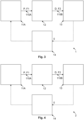
- Figure 1 depicts a simplified schematic of major energy pathways in the brain include glycolysis, which takes places in the cytosol and produces pyruvate, which enters mitochondria and is converted into acetyl CoA that enters the TCA cycle. Alternatively, pyruvate can stay in the cytosol and is converted into lactate that is exported out of the cell.
- the pentose phosphate pathway (PPP) takes place in the cytosol and is an alternative energy pathway that can be up-regulated after injury; it is an important source of NADPH used to produce the reduced form of glutathione (GSH) for preventing oxidative stress.
- PPP pentose phosphate pathway
- Figure 2A is a photograph of a microdialysis probe inserted into a brain of a patient; and Figure 2B is a magnetic resonance imaging (MRI) scan of a microdialysis probe inserted into a brain of a patient.
- Figure 2A shows the microdialysis probe together with an oxygen sensor for cerebral oximetry and a pressure sensor for intracranial pressure monitoring inserted into the brain of the patient.
- Figure 2B depicts an MRI scan, using 3D MP-RAGE sequence, at 3 Tesla, showing the brain of a TBI patient with a microdialysis catheter (via a cranial access device) in position, the catheter tip indicated by an arrow (yellow). Scale bar (green) shows centimetre divisions.
- FIG. 3 schematically depicts a detector assembly 1 according to an exemplary embodiment.
- the detector assembly 1 is for determining a ratio of lactate to pyruvate from dialysis, preferably microdialysis for example cerebral microdialysis.
- the detector assembly comprises: a first pump 11A of a set of pumps 11, a dialysis probe 12, preferably a microdialysis probe, having an inlet 121 (not shown) and an outlet 122 (not shown), a first tube 110A of a set of tubes 110 arranged to fluidically couple the first pump 11A to the inlet 121 of the dialysis probe 12, an infrared, IR, detector 13, a second tube 110B of the set of tubes 110 arranged to fluidically couple the outlet 122 of the dialysis probe 12 to the IR detector 13 and a controller 14; wherein the first pump 11A is arranged to pump a perfusate P at a first flow rate F1 of a set of flow rates to the dialysis probe 12, inserted into a
- the IR detector 13 comprises a flow cell 131 arranged proximal to the outlet 122 of the dialysis probe 12, for example within 500 mm, preferably within 250 mm, more preferably within 100 mm of the outlet of the dialysis probe 12.
- Figure 4 schematically depicts a detector assembly 2 according to an exemplary embodiment.
- the detector assembly 2 is generally as described with respect to the detector assembly 1.
- the detector assembly 2 comprises a first valve 15A (not shown) of a set of valves 15 arranged to direct the dialysate D at the second flow rate F2 of the set of flow rates from the outlet of the dialysis probe 12 to the IR detector 13 via the second tube 110B and the set of pumps 11 comprises a second pump 11B (not shown) arranged to pump, at least in part, the dialysate D at the second flow rate F2 of the set of flow rates from the dialysis probe 12 to the IR detector 13 via the second tube 110B, wherein the second flow rate F2 is greater than the first flow rate F1.
- the IR detector 13 comprises a flow cell 131 arranged proximal to the outlet 122 of the dialysis probe 12, for example within 500 mm, preferably within 250 mm, more preferably within 100 mm of the outlet of the dialysis probe 12.
- the flow cell 131 may be remote from the IR detector 13 (particularly, an absorbance sensor thereof), coupled thereto via optical fibres for example (i.e. via a first optical fibre to an IR source and via a second optical fibre to the absorbance sensor).
- FIG. 5 is a photograph of an infrared (IR) detector 13 for a detector assembly 1, 2 according to an exemplary embodiment.
- the IR detector 13 comprises an IR source, particularly a QCL, a flow cell and an absorbance sensor.
- An inlet of the flow cell is fluidically coupled to an end of the second tube and an outlet of the flow cell is fluidically coupled to an end of a third tube of the set of tubes, for collection of the dialysate D in a vial, for example, for subsequent analysis.
- measurements were acquired using a ChemDetect Analyzer (Daylight Solutions, Inc.), comprising a tunable QCL light source, a microfluidic flow-cell and a thermoelectrically-cooled InAsSb (indium arsenide antimonide) detector.
- the QCL is broadly tunable within the MIR fingerprint region between 982 and 1258 cm -1 , and sweeps are made with 0.2 cm -1 steps and averaged to 2 cm -1 resolution. A single sweep is taken in approximately 1 second, but several sweeps can be averaged for an increased SNR in the final spectrum.
- a cooling system (UC160-190, Solid State Cooling Systems, USA) was used in conjunction with ChemDetect Analyzer to ensure temperature stability during measurements by recirculating a mixture of chilled water and liquid coolant (702 Liquid Coolant, Koolance, South Korea) in the bottom plate of the instrument via two rear inlet/outlet connectors.
- the flow-cell of ChemDetect is the core of the sample interface. It has a small channel volume of 1 ⁇ L and a path-length, which can be adjusted through the selection of different polytetrafluoroethylene (PTFE)-gasket thicknesses, between 25 and 200 ⁇ m.
- PTFE polytetrafluoroethylene
- the flow-cell incorporates two diamond windows through which the laser beam transmits to interact with the flowing sample.
- Inlet and outlet tubing are connected to the flow-cell using appropriate connectors (M660 Nut and super flangeless M650 Ferrule for 1.6 mm OD tubing, Cole-Parmer Ltd., UK).
- the flow-cell is mounted into the sample compartment using alignment pins and attachment screws, and two coned 10-32 ports are used to connect external sample-carrying tubing to the ChemDetect, allowing the sample to enter/exit the inlet/outlet tubing of the flow-cell.
- the cell can easily be disassembled for cleaning and/or gasket changing if different optical path-lengths are required.
- Figure 6A is a photograph of a flow cell for an infrared (IR) detector 13 for a detector assembly 1, 2 according to an exemplary embodiment
- Figure 6B is a photograph of a flow cell for an infrared (IR) detector 13 for a detector assembly 1, 2 according to an exemplary embodiment
- Figure 6C is a photograph of a flow cell for an infrared (IR) detector 13 for a detector assembly 1, 2 according to an exemplary embodiment.
- these flow cells are configured to be remote from the IR detector 13 (particularly, an absorbance sensor thereof), coupled thereto via optical fibres for example (i.e. via a first optical fibre to an IR source and via a second optical fibre to the absorbance sensor).
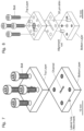
- FIG 7 is an exploded perspective CAD drawing of the flow cell of Figure 6A , in more detail.
- Figure 7 is an exploded perspective CAD drawing of the flow cell of Figure 6A , showing the different components comprising the latter.
- This flow cell consists of two layers of polytetrafluoroethylene (PTFE), which are stacked and tightly assembled using four bolts.
- the bottom layer provides a channel for the sample fluid to flow through and also holds two lateral and aligned holes to place a fibre optic cable on either side of the channel.
- the analytes within the flowing sample are detected via transmission of light through the channel, from one fibre to the other.
- the top layer comprises of two holes at the same distance apart as the channel length, which serve as the channel inlet and outlet, where the sample-carrying tubing is inserted.
- the channel volume of this flow-cell is 2.5 ⁇ L.
- Figure 8 is an exploded perspective CAD drawing of the flow cell of Figure 6B .
- Figure 8 is an exploded perspective CAD drawing of the flow cell of Figure 6B .
- This flow cell comprises of three stainless-steel layers which are stacked and fastened together using four bolts. All three layers provide four threaded holes to accept the bolts and two smaller holes for inserting stainless-steel alignment rods which are used to ensure careful alignment of the layers during assembly.
- the top and bottom layers provide a central threaded hole for connecting two optical fibres.
- a rubber O-ring of 2 mm inner diameter is initially placed in the connector insert before connecting the fibres.
- the top layer provides an additional two holes, which are used as the channel inlet and outlet, where hollow PTFE cylinders are inserted to provide a tight fit for the sample-carrying tubing.
- the middle layer consists of a 50 ⁇ m stainless-steel shim and provides the fluidic channel.
- the fibre inserted in the top layer is used as the light source while the fibre inserted in the bottom layer is used as the light detector.
- the channel volume of this flow-cell is 1.6 ⁇ L.
- Figure 9A is a perspective CAD drawing of the flow cell of Figure 6C ; and Figure 9B is a cross-sectional view of the flow cell of Figure 9A .
- Figure 9A is a perspective CAD drawing of the flow cell of Figure 6C ;
- Figure 9B is a cross-sectional view of the flow cell of Figure 9A .
- This flow cell comprises of two PEEK layers (top and bottom) and one PTFE gasket, which is sandwiched between the two layers using four bolts.
- the top layer holds two lateral threaded holes to insert a standard tubbing connector on either side of the flow-cell.
- the top and bottom layers provide a central threaded hole for connecting optical fibres, one which is used as the light source and the other which is used as the light detector.
- the channel volume of this flow-cell is 0.65 ⁇ L.
- Figure 10 schematically depicts a method according to an exemplary embodiment.
- the method is of determining a ratio of lactate to pyruvate from dialysis, preferably microdialysis for example cerebral microdialysis.
- a perfusate is pumped, by a first pump of a set of pumps, at a first flow rate of a set of flow rates to a dialysis probe, preferably a microdialysis probe, inserted into a fluid, for example a bodily fluid, and/or an organ of and/or for a patient, via a first tube of a set of tubes and in turn pumping, at least in part, a dialysate at a second flow rate of the set of flow rates from the dialysis probe to an infrared, IR, detector via a second tube of the set of tubes.
- a dialysis probe preferably a microdialysis probe
- respective absorbances due, at least in part, to lactate and pyruvate in the dialysate are detected, by the IR detector.
- the ratio of lactate to pyruvate in the dialysate is determined, by a controller, based, at least in part, on the detected respective absorbances.
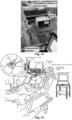
- Figure 11 is a photograph of a detector assembly 3 according to an exemplary embodiment, in use, particularly for in vitro analysis.
- the IR detector 13 comprises the flow cell 131C, as described above.
- Figure 12 schematically depicts a detector assembly 4 according to an exemplary embodiment, in use, particularly for in vitro analysis or ex vivo analysis.
- the dialysis probe 12 is inserted into synthetic extracellular brain fluid at 37 °C (i.e. human body temperature).
- the IR detector 13 comprises the flow cell 131C, as described above.
- Figure 12 shows the laboratory setup created to mimic clinical monitoring using the ChemDetect Analyzer in order to assess its performance for carrying out continuous microdialysate monitoring in conjunction with the clinically used standard microdialysis catheter and pump.
- an external standard (ES) solution i.e. artificial extracellular brain fluid
- HAS human serum albumin
- S2002 0.05 % w/v sodium azide
- a desired amount of any or all metabolites can be added at the beginning or throughout the experiment in order to track changes.
- a small magnetic stirrer was added to the ES in the Falcon tube, after which a 20 cm 2 of cling film was folded into a 4-layer square and used to cover the top of the open tube, secured by a rubber band.
- the cling film was then gently pierced and a triple lumen cranial access device held in place in the-Falcon tube within a glycerol (G9012, ⁇ 99.5%, Sigma-Aldrich) bath on a thermostatically-controlled hotplate-stirrer (97042-754, VWR, USA) at 37°C, with the stirrer speed set to 60 rpm.
- a standard MD catheter 8010320, M Dialysis 71 High Cut-Off Brain Microdialysis Catheter, M Dialysis AB, Sweden, with 100 kDa MWCO and a 10 mm membrane length was placed into the ES through the triple lumen cranial access device.
- Figure 13 is a photograph of a detector assembly 5 according to an exemplary embodiment, in use, particularly for in vivo analysis.
- Figure 14 schematically depicts a detector assembly 6 according to an exemplary embodiment, in use, particularly for in vivo analysis.
- the flow cell is arranged proximal the outlet of the microdialysis probe.
- Figure 15A is a graph of absorbance as a function of wavenumber for 24 mM glucose for path lengths of 20 ⁇ m, 50 ⁇ m and 100 ⁇ m
- Figure 15B is a graph of absorbance as a function of wavenumber for 6 mM glucose for path lengths of 20 ⁇ m, 50 ⁇ m and 100 ⁇ m
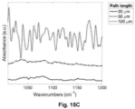
- Figure 15C is a graph of absorbance as a function of wavenumber for 1.5 mM glucose for path lengths of 20 ⁇ m, 50 ⁇ m and 100 ⁇ m.
- the absorbances were measured using the detector assembly 3, generally as described with respect to Figure 11 , measured on standard FTIR with transmission cell accessory (Pearl, Specac) using different cell path-lengths: 20, 50 and 100 ⁇ m.
- the results obtained with a path-length of 50 ⁇ m showed higher S-N-R. Note: For clarity, each spectrum has been plotted with a vertical offset with respect to the other spectra.
- Figure 16A is a graph of absorbance as a function of wavenumber for 1.5 mM glucose and 1.5 mM pyruvate for a path length of 127 ⁇ m; and Figure 16B is a graph of absorbance as a function of wavenumber for 1 mM pyruvate for path lengths of 76 ⁇ m, 127 ⁇ m, 150 ⁇ m and 200 ⁇ m.
- the absorbances were measured using the detector assembly 3, generally as described with respect to Figure 11 , measured on a ChemDetect IR detector. The results obtained with a path-length of 127 ⁇ m showed higher S-N-R. Note: For clarity, each spectrum has been plotted with a vertical offset with respect to the other spectra.
- SNR signal-to-noise
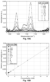
- Figure 18A is a graph of absorbance as a function of wavenumber for pyruvate (1.5mM), lactate (1.5 mM) and glucose (1.5 mM), for a path length of 127 ⁇ m;
- the calibration curve of Figure 18C is linear.
- Figure 19B is a graph of relative peak height as a function of concentration for lactate (wavenumber 1124 cm -1 ) having a concentration in a range from 0 to 12 mM for a path length of 127 ⁇ m.
- the calibration curve of Figure 19B is linear.
- the calibration curve of Figure 20B is linear.
- the absorbance increases linearly with concentration and is relatively constant as a function of time for a given concentration.
- the response time is entirely dependent on the tubing length and flow-rate.
- a standard flow-rate of 0.3 ⁇ L/min was used but a smaller tubing length (20 cm of 0.15 mm ID tubing + 4 cm of 0.3 mm ID tubing) in order to speed up the process.
- the lag time will correspond to approx. 23.50 mins for a flow-rate of 0.3 ⁇ L/min through 20 cm of 0.15 mm ID tubing + 4 cm of 0.3 mm ID tubing + adaptor.
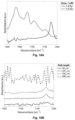
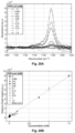
- Figure 22 depicts infra-red (IR) sensor signals collected during 2 hours of microdialysis, in a TBI patient, showing a stacked plot of the spectra, with the position of peaks for glucose, lactate and pyruvate indicated.
- IR infra-red
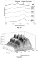
- Figure 23A is a 3-dimensional graph of infra-red (IR) absorbance as a function of time and wavenumber for a TBI patient, showing 21 hours of monitoring. These spectra suggest variations with time for glucose and lactate, accompanied by a relatively constant level of pyruvate.
- Figure 24 is a graph of a ratio of lactate to pyruvate as a function of time for the patient of Figures 23A to 23B .
- Other methods such a multivariate analysis may offer an alternative and/or a more accurate method of ratio determination.
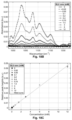
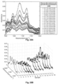
- Figure 25A shows the mid-infrared spectra of the 16 samples of patient 1 as well as the corresponding concentrations of each compound obtained from the ISCUSflex analysis.
- Three strong peaks were observed in all spectra at 1042 cm -1 , 1080 cm -1 , and 1124 cm -1 .
- An immediate analysis suggests that these correspond to the C-O stretches of lactate (1124 cm -1 and 1042 cm -1 ) and glucose (1080 cm -1 ).
- the glucose peak at 1080 cm -1 is prominent compared to its usually stronger peak at 1036 cm -1 , which is not seen in the spectra, it is possible that there is a large contribution from the weak lactate peak at 1086 cm -1 .
- Figures 25D demonstrates a strong correlation between the absorbance intensities of the (predominant) glucose peaks and these glucose concentrations (i.e. when the glucose concentration increases, the absorbance intensities of the glucose peaks increase and vice-versa).
- Figure 25E shows agreement between peak intensities for lactate measured on the ChemDetect Analyzer and the concentrations obtained by the ISCUSflex.
- Figures 25F to 25G show limit of quantitation (LOQ) determinations for glucose, lactate and pyruvate, respectively, as summarised in Table 2. Table 2: LOQ for analytes of interest.
- PLSR Partial Least Squares Regression
- Synthetic samples were used for development of a Partial Least Squares Regression (PLSR) model for subsequent use in predicting patient-sample concentrations.
- PLSR Partial Least Squares Regression
- a simple uniform selection algorithm with reject sampling was developed and used to generate a list of 50 samples containing different combinations of glucose, lactate and pyruvate concentrations within ranges that are typical TBI-patient microdialysate compound concentrations
- Four outliers were excluded, and the remaining 46 spectra used to generate and test the model are shown in Figure 26A .
- the first derivative of the spectra was calculated and the spectral range used was between 1025 and 1150 cm -1 .
- the processed spectra are shown in Figure 26B .
- a PLSR model was built, and the number of PLSR components used, 3 was calibrated based on k-fold cross validation, where the spectral data were randomly split into the following sub-sample sets: the in-sample set, comprising of 19 spectra; the out-sample set comprising of 13 spectra; and the test sample set, comprising of the remaining 14 spectra.
- a single sub-sample (test sample) was retained as the final validation for testing of the model.
- the performance of the PLSR model in predicting each compound was evaluated using the Root Mean Squared Error (RMSE) of each compound in the test set as shown in Table 3.
- RMSE Root Mean Squared Error
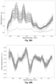
- FIGS. 28A and 28B show the absorbance spectra obtained for each sample, plotted in the relevant spectral range, before and after data preprocessing.
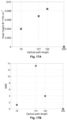
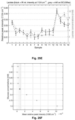
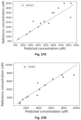
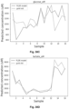
- Figures 29A and 29B show the predicted glucose and lactate concentrations for the 40 microdialysis samples from patient 2.
- the respective RMSE values for each compound are shown in Table 4.
- Table 4 RMSE for analytes of interest Test sample RMSE ( ⁇ M ) glucose 796 lactate 809
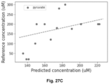
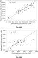
- Figures 30A and 30B show the concentrations; real vs. predicted for the consecutively collected patient 2 samples. The results show that there is a very good correlation between the gold standard (ISCUSflex) and the developed model.
- Figures 30C and 30D similarly show the concentrations; real vs. predicted for the 16 consecutively collected patient 1 samples. The results again show that there is a very good correlation between the gold standard (ISCUSflex) and the developed model.
Landscapes
- Health & Medical Sciences (AREA)
- Life Sciences & Earth Sciences (AREA)
- Heart & Thoracic Surgery (AREA)
- Physics & Mathematics (AREA)
- General Health & Medical Sciences (AREA)
- Animal Behavior & Ethology (AREA)
- Biomedical Technology (AREA)
- Engineering & Computer Science (AREA)
- Public Health (AREA)
- Veterinary Medicine (AREA)
- Urology & Nephrology (AREA)
- Pathology (AREA)
- Hematology (AREA)
- Anesthesiology (AREA)
- Vascular Medicine (AREA)
- Emergency Medicine (AREA)
- Biophysics (AREA)
- Surgery (AREA)
- Molecular Biology (AREA)
- Medical Informatics (AREA)
- Spectroscopy & Molecular Physics (AREA)
- Optics & Photonics (AREA)
- Neurology (AREA)
- Chemical & Material Sciences (AREA)
- Immunology (AREA)
- General Physics & Mathematics (AREA)
- Biochemistry (AREA)
- Analytical Chemistry (AREA)
- Neurosurgery (AREA)
- Physiology (AREA)
- Psychology (AREA)
- External Artificial Organs (AREA)
Claims (14)
- Detektoranordnung (1) zum Bestimmen eines Verhältnisses von Laktat zu Pyruvat aus der Dialyse, vorzugsweise der Mikrodialyse, beispielsweise der zerebralen Mikrodialyse, wobei die Detektoranordnung umfasst:eine erste Pumpe (11A) einer Gruppe von Pumpen (11), eine Dialysesonde (12), vorzugsweise eine Mikrodialysesonde, mit einem Einlass (121) und einem Auslass (122), einem ersten Schlauch (110A) einer Gruppe von Schläuchen (110), der dafür ausgelegt ist, die erste Pumpe (11A) mit dem Einlass (121) der Dialysesonde (12) fluidisch zu koppeln, einen Infrarot, IR, -Detektor (13), einen zweiten Schlauch (110B) der Gruppe von Schläuchen (110), der dafür ausgelegt ist, den Auslass (122) der Dialysesonde (12) mit dem IR-Detektor (13) fluidisch zu koppeln, und eine Steuerung (14);wobei die erste Pumpe (11A) dafür ausgelegt ist, ein Perfusat (P) mit einer ersten Fließgeschwindigkeit (F1) einer Gruppe von Fließgeschwindigkeiten über den ersten Schlauch (110A) zur Dialysesonde (12) zu pumpen, die in eine Flüssigkeit oder ein Organ eines Patienten eingeführt ist, und wiederum wenigstens teilweise ein Dialysat (D) mit einer zweiten Fließgeschwindigkeit (F2) der Gruppe von Fließgeschwindigkeiten von der Dialysesonde (12) über den zweiten Schlauch (110B) zum IR-Detektor (13) zu pumpen, wobei das Perfusat (P) in den Einlass (121) der Dialysesonde (12) eintritt und das Dialysat (D) aus dem Auslass (122) der Dialysesonde (12) austritt;wobei der IR-Detektor (13) dafür ausgelegt ist, jeweilige Absorptionen zu detektieren, die wenigstens teilweise auf Laktat und Pyruvat im Dialysat (D) zurückzuführen sind; undwobei die Steuerung (14) dafür ausgelegt ist, das Verhältnis von Laktat zu Pyruvat im Dialysat (D) basierend, wenigstens teilweise, auf den detektierten jeweiligen Absorptionswerten zu bestimmen.
- Detektoranordnung (1) nach einem der vorstehenden Ansprüche, wobei der IR-Detektor (13) dafür ausgelegt ist, eine Absorption zu detektieren, die wenigstens teilweise auf Glukose, Glutamat, Alanin, Glutamin und/oder Glycerin im Dialysat zurückzuführen ist.
- Detektoranordnung (1) nach einem der vorstehenden Ansprüche, wobei die Steuerung (14) dafür ausgelegt ist, ein erstes Ausgangssignal bereitzustellen, basierend, wenigstens teilweise, auf dem Verhältnis von Laktat zu Pyruvat im Dialysat (D), um die Infusion eines Infusats in die Flüssigkeit und/oder das Organ zu steuern.
- Detektoranordnung (1) nach einem der vorstehenden Ansprüche, wobei die Steuerung (14) dafür ausgelegt ist, ein zweites Ausgangssignal bereitzustellen, basierend, wenigstens teilweise, auf einer Veränderung, vorzugsweise einer Änderungsrate, einer detektierten Absorption, beispielsweise von Glukose.
- Detektoranordnung (1) nach einem der vorstehenden Ansprüche, wobei die Steuerung (14) dafür ausgelegt ist, das Verhältnis von Laktat zu Pyruvat im Dialysat periodisch und/oder kontinuierlich zu bestimmen.
- Detektoranordnung (1) nach einem der vorstehenden Ansprüche, wobei die Steuerung (14) dafür ausgelegt ist, das Verhältnis von Laktat zu Pyruvat im Dialysat (D) online und/oder in Echtzeit zu bestimmen.
- Detektoranordnung (1) nach einem der vorstehenden Ansprüche, wobei die Gruppe von Pumpen (11) eine zweite Pumpe (11B) umfasst, die dafür ausgelegt ist, wenigstens teilweise, das Dialysat (D) mit der zweiten Fließgeschwindigkeit (F2) der Gruppe von Fließgeschwindigkeiten von der Dialysesonde (12) über den zweiten Schlauch (110B) zum IR-Detektor (13) zu pumpen, wobei die zweite Fließgeschwindigkeit (F2) größer als die erste Fließgeschwindigkeit (F1) ist.
- Detektoranordnung (1) nach Anspruch 6, wobei die Steuerung (14) dafür ausgelegt ist, die zweite Pumpe (110B) zu steuern, um das Dialysat (F2) mit der zweiten Fließgeschwindigkeit (F2) der Gruppe von Fließgeschwindigkeiten zu pumpen.
- Detektoranordnung (1) nach einem der vorstehenden Ansprüche, die ein erstes Ventil einer Gruppe von Ventilen, die dafür ausgelegt sind, das Dialysat (D) mit der zweiten Fließgeschwindigkeit (F2) der Gruppe von Fließgeschwindigkeiten vom Auslass (122) der Dialysesonde (12) über den zweiten Schlauch (110B) zum IR-Detektor (13) zu leiten, umfasst.
- Detektoranordnung (1) nach einem der vorstehenden Ansprüche, wobei der IR-Detektor (13) eine Durchflusszelle umfasst, die in der Nähe des Auslasses (122) der Dialysesonde (12) angeordnet ist.
- Detektoranordnung (1) nach einem der vorstehenden Ansprüche, wobei die Steuerung (14) dafür ausgelegt ist, das Verhältnis von Laktat zu Pyruvat im Dialysat (D) mit entsprechenden Ausgangssignalen von einer Gruppe von Patientensensoren, die beispielsweise einen Sauerstoffsensor und/oder einen Drucksensor beinhalten, zu vergleichen.
- Detektoranordnung (1) nach einem der vorstehenden Ansprüche, wobei der erste Schlauch einen Innendurchmesser in einem Bereich von 10 µm bis 1.000 µm, vorzugsweise in einem Bereich von 50 µm bis 500 µm, besonders bevorzugt in einem Bereich von 100 µm bis 250 µm, beispielsweise 150 µm, aufweist; und/oder wobei der erste Schlauch eine Länge in einem Bereich von 10 mm bis 1.000 mm, vorzugsweise in einem Bereich von 50 mm bis 500 mm, besonders bevorzugt in einem Bereich von 100 mm bis 250 mm aufweist.
- Detektoranordnung (1) nach einem der vorstehenden Ansprüche, wobei der zweite Schlauch einen Innendurchmesser in einem Bereich von 10 µm bis 1.000 µm, vorzugsweise in einem Bereich von 50 µm bis 500 µm, besonders bevorzugt in einem Bereich von 100 µm bis 250 µm, beispielsweise 150 µm, aufweist; und/oder wobei der zweite Schlauch eine Länge in einem Bereich von 10 mm bis 1.000 mm, vorzugsweise in einem Bereich von 50 mm bis 500 mm, besonders bevorzugt in einem Bereich von 100 mm bis 750 mm, beispielsweise 600 mm, aufweist.
- Detektoranordnung (1) nach einem der vorstehenden Ansprüche, wobei der IR-Detektor einen auf einem Quantenkaskadenlaser (QCL, Quantum Cascade Laser) basierenden IR-Detektor umfasst und/oder ein solcher ist.
Applications Claiming Priority (2)
| Application Number | Priority Date | Filing Date | Title |
|---|---|---|---|
| GBGB1916168.6A GB201916168D0 (en) | 2019-11-06 | 2019-11-06 | Detector assembly and method |
| PCT/GB2020/052815 WO2021090017A1 (en) | 2019-11-06 | 2020-11-06 | Detector assembly and method |
Publications (3)
| Publication Number | Publication Date |
|---|---|
| EP4054401A1 EP4054401A1 (de) | 2022-09-14 |
| EP4054401B1 true EP4054401B1 (de) | 2025-02-19 |
| EP4054401C0 EP4054401C0 (de) | 2025-02-19 |
Family
ID=69059100
Family Applications (1)
| Application Number | Title | Priority Date | Filing Date |
|---|---|---|---|
| EP20804646.6A Active EP4054401B1 (de) | 2019-11-06 | 2020-11-06 | Detektoranordnung |
Country Status (5)
| Country | Link |
|---|---|
| US (1) | US20220387680A1 (de) |
| EP (1) | EP4054401B1 (de) |
| CA (1) | CA3156966A1 (de) |
| GB (1) | GB201916168D0 (de) |
| WO (1) | WO2021090017A1 (de) |
Family Cites Families (9)
| Publication number | Priority date | Publication date | Assignee | Title |
|---|---|---|---|---|
| DE10328998A1 (de) * | 2003-06-27 | 2005-01-20 | Bayer Technology Services Gmbh | IR-ATR basiertes Verfahren und Vorrichtung zur Analyse geringster Probenmengen |
| US20070258083A1 (en) * | 2006-04-11 | 2007-11-08 | Optiscan Biomedical Corporation | Noise reduction for analyte detection systems |
| WO2009008830A1 (en) * | 2007-07-10 | 2009-01-15 | Cma Microdialysis Ab | Linear device for microdialysis, method of manufacturing the device and method for studying a tissue with the device |
| US9763610B2 (en) * | 2009-12-30 | 2017-09-19 | Maquet Critical Care Mb | System and method for continuously monitoring and presenting body substances |
| EP2593790A4 (de) * | 2010-07-14 | 2015-04-01 | Univ Colorado Regents | Verfahren und systeme zur in-vivo-messung klinischer daten von analyten |
| US9814413B2 (en) * | 2014-07-24 | 2017-11-14 | Thomas Jefferson University | Long-term implantable monitoring system and methods of use |
| GB2538731B (en) * | 2015-05-26 | 2019-05-22 | Imperial Innovations Ltd | Methods |
| US11661586B2 (en) * | 2017-12-04 | 2023-05-30 | The General Hospital Corporation | Extracellular redox enzyme system to alleviate disease |
| US20200355605A1 (en) * | 2019-03-05 | 2020-11-12 | Optiscan Biomedical Corporation | Automated fluid analysis using tunable optical sources |
-
2019
- 2019-11-06 GB GBGB1916168.6A patent/GB201916168D0/en not_active Ceased
-
2020
- 2020-11-06 CA CA3156966A patent/CA3156966A1/en active Pending
- 2020-11-06 US US17/774,885 patent/US20220387680A1/en active Pending
- 2020-11-06 EP EP20804646.6A patent/EP4054401B1/de active Active
- 2020-11-06 WO PCT/GB2020/052815 patent/WO2021090017A1/en not_active Ceased
Also Published As
| Publication number | Publication date |
|---|---|
| US20220387680A1 (en) | 2022-12-08 |
| WO2021090017A1 (en) | 2021-05-14 |
| CA3156966A1 (en) | 2021-05-14 |
| EP4054401C0 (de) | 2025-02-19 |
| EP4054401A1 (de) | 2022-09-14 |
| GB201916168D0 (en) | 2019-12-18 |
Similar Documents
| Publication | Publication Date | Title |
|---|---|---|
| Hutchinson et al. | Consensus statement from the 2014 international microdialysis forum | |
| EP1545296B1 (de) | Kalibrationstechnik für nichtinvasive medizinische vorrichtungen | |
| Hillered et al. | Translational neurochemical research in acute human brain injury: the current status and potential future for cerebral microdialysis | |
| Bolincier et al. | Microdialysis measurement of the absolute glucose concentration in subcutaneous adipose tissue allowing glucose monitoring in diabetic patients | |
| Mohammadi et al. | In vivo evaluation of a chip based near infrared sensor for continuous glucose monitoring | |
| Bhatia et al. | Neuromonitoring in the intensive care unit. II. Cerebral oxygenation monitoring and microdialysis | |
| US20110009720A1 (en) | Continuous whole blood glucose monitor | |
| US20040260162A1 (en) | Analysis system for reagent-free determination of the concentration of an analyte in living tissue | |
| Rogers et al. | Real-time clinical monitoring of biomolecules | |
| CN109171761A (zh) | 对生物体进行监视的监视器和系统 | |
| US20120035583A1 (en) | Multimode neurobiophysiology probe | |
| Gupta | Monitoring the injured brain in the intensive care unit | |
| Gowers et al. | An improved rapid sampling microdialysis system for human and porcine organ monitoring in a hospital setting | |
| Landolt et al. | Cerebral microdialysis as a diagnostic tool in acute brain injury | |
| Sarrafzadeh et al. | Neuromonitoring: brain oxygenation and microdialysis | |
| Lang et al. | Invasive neuromonitoring modalities in the pediatric population | |
| EP4054401B1 (de) | Detektoranordnung | |
| Rhemrev-Boom et al. | A lightweight measuring device for the continuous in vivo monitoring of glucose by means of ultraslow microdialysis in combination with a miniaturised flow-through biosensor | |
| De Boer et al. | In vivo monitoring of lactate and glucose with microdialysis and enzyme reactors in intensive care medicine | |
| US20100062478A1 (en) | Drug for analysis of water transport function of membrane protein in biological tissue | |
| Klaus et al. | Clinical biochemical tissue monitoring during ischaemia and reperfusion in major vascular surgery | |
| Gu et al. | Development of a real-time blood damage monitoring device for cardiopulmonary bypass system using near-infrared spectroscopy | |
| Dager et al. | Application of a novel fiber-optic biosensor in situ to investigate the metabolic effect of lactate infusion | |
| Boutelle | Analytical Methods | |
| Hollinger et al. | Brain Tissue Oxygenation |
Legal Events
| Date | Code | Title | Description |
|---|---|---|---|
| STAA | Information on the status of an ep patent application or granted ep patent |
Free format text: STATUS: UNKNOWN |
|
| STAA | Information on the status of an ep patent application or granted ep patent |
Free format text: STATUS: THE INTERNATIONAL PUBLICATION HAS BEEN MADE |
|
| PUAI | Public reference made under article 153(3) epc to a published international application that has entered the european phase |
Free format text: ORIGINAL CODE: 0009012 |
|
| STAA | Information on the status of an ep patent application or granted ep patent |
Free format text: STATUS: REQUEST FOR EXAMINATION WAS MADE |
|
| 17P | Request for examination filed |
Effective date: 20220606 |
|
| AK | Designated contracting states |
Kind code of ref document: A1 Designated state(s): AL AT BE BG CH CY CZ DE DK EE ES FI FR GB GR HR HU IE IS IT LI LT LU LV MC MK MT NL NO PL PT RO RS SE SI SK SM TR |
|
| DAV | Request for validation of the european patent (deleted) | ||
| DAX | Request for extension of the european patent (deleted) | ||
| GRAP | Despatch of communication of intention to grant a patent |
Free format text: ORIGINAL CODE: EPIDOSNIGR1 |
|
| STAA | Information on the status of an ep patent application or granted ep patent |
Free format text: STATUS: GRANT OF PATENT IS INTENDED |
|
| INTG | Intention to grant announced |
Effective date: 20240920 |
|
| GRAS | Grant fee paid |
Free format text: ORIGINAL CODE: EPIDOSNIGR3 |
|
| GRAA | (expected) grant |
Free format text: ORIGINAL CODE: 0009210 |
|
| STAA | Information on the status of an ep patent application or granted ep patent |
Free format text: STATUS: THE PATENT HAS BEEN GRANTED |
|
| AK | Designated contracting states |
Kind code of ref document: B1 Designated state(s): AL AT BE BG CH CY CZ DE DK EE ES FI FR GB GR HR HU IE IS IT LI LT LU LV MC MK MT NL NO PL PT RO RS SE SI SK SM TR |
|
| REG | Reference to a national code |
Ref country code: GB Ref legal event code: FG4D |
|
| REG | Reference to a national code |
Ref country code: CH Ref legal event code: EP |
|
| REG | Reference to a national code |
Ref country code: IE Ref legal event code: FG4D |
|
| REG | Reference to a national code |
Ref country code: DE Ref legal event code: R096 Ref document number: 602020046411 Country of ref document: DE |
|
| U01 | Request for unitary effect filed |
Effective date: 20250224 |
|
| U07 | Unitary effect registered |
Designated state(s): AT BE BG DE DK EE FI FR IT LT LU LV MT NL PT RO SE SI Effective date: 20250228 |
|
| PG25 | Lapsed in a contracting state [announced via postgrant information from national office to epo] |
Ref country code: RS Free format text: LAPSE BECAUSE OF FAILURE TO SUBMIT A TRANSLATION OF THE DESCRIPTION OR TO PAY THE FEE WITHIN THE PRESCRIBED TIME-LIMIT Effective date: 20250519 |
|
| PG25 | Lapsed in a contracting state [announced via postgrant information from national office to epo] |
Ref country code: PL Free format text: LAPSE BECAUSE OF FAILURE TO SUBMIT A TRANSLATION OF THE DESCRIPTION OR TO PAY THE FEE WITHIN THE PRESCRIBED TIME-LIMIT Effective date: 20250219 |
|
| PG25 | Lapsed in a contracting state [announced via postgrant information from national office to epo] |
Ref country code: ES Free format text: LAPSE BECAUSE OF FAILURE TO SUBMIT A TRANSLATION OF THE DESCRIPTION OR TO PAY THE FEE WITHIN THE PRESCRIBED TIME-LIMIT Effective date: 20250219 |
|
| PG25 | Lapsed in a contracting state [announced via postgrant information from national office to epo] |
Ref country code: IS Free format text: LAPSE BECAUSE OF FAILURE TO SUBMIT A TRANSLATION OF THE DESCRIPTION OR TO PAY THE FEE WITHIN THE PRESCRIBED TIME-LIMIT Effective date: 20250619 Ref country code: NO Free format text: LAPSE BECAUSE OF FAILURE TO SUBMIT A TRANSLATION OF THE DESCRIPTION OR TO PAY THE FEE WITHIN THE PRESCRIBED TIME-LIMIT Effective date: 20250519 |
|
| PG25 | Lapsed in a contracting state [announced via postgrant information from national office to epo] |
Ref country code: HR Free format text: LAPSE BECAUSE OF FAILURE TO SUBMIT A TRANSLATION OF THE DESCRIPTION OR TO PAY THE FEE WITHIN THE PRESCRIBED TIME-LIMIT Effective date: 20250219 |
|
| PG25 | Lapsed in a contracting state [announced via postgrant information from national office to epo] |
Ref country code: GR Free format text: LAPSE BECAUSE OF FAILURE TO SUBMIT A TRANSLATION OF THE DESCRIPTION OR TO PAY THE FEE WITHIN THE PRESCRIBED TIME-LIMIT Effective date: 20250520 |
|
| PG25 | Lapsed in a contracting state [announced via postgrant information from national office to epo] |
Ref country code: SM Free format text: LAPSE BECAUSE OF FAILURE TO SUBMIT A TRANSLATION OF THE DESCRIPTION OR TO PAY THE FEE WITHIN THE PRESCRIBED TIME-LIMIT Effective date: 20250219 |
|
| PG25 | Lapsed in a contracting state [announced via postgrant information from national office to epo] |
Ref country code: CZ Free format text: LAPSE BECAUSE OF FAILURE TO SUBMIT A TRANSLATION OF THE DESCRIPTION OR TO PAY THE FEE WITHIN THE PRESCRIBED TIME-LIMIT Effective date: 20250219 |
|
| PG25 | Lapsed in a contracting state [announced via postgrant information from national office to epo] |
Ref country code: SK Free format text: LAPSE BECAUSE OF FAILURE TO SUBMIT A TRANSLATION OF THE DESCRIPTION OR TO PAY THE FEE WITHIN THE PRESCRIBED TIME-LIMIT Effective date: 20250219 |
|
| PLBE | No opposition filed within time limit |
Free format text: ORIGINAL CODE: 0009261 |
|
| STAA | Information on the status of an ep patent application or granted ep patent |
Free format text: STATUS: NO OPPOSITION FILED WITHIN TIME LIMIT |
|
| U20 | Renewal fee for the european patent with unitary effect paid |
Year of fee payment: 6 Effective date: 20251126 |
|
| PGFP | Annual fee paid to national office [announced via postgrant information from national office to epo] |
Ref country code: GB Payment date: 20251230 Year of fee payment: 6 |
|
| 26N | No opposition filed |
Effective date: 20251120 |