EP4053954A1 - Secondary battery and manufacturing method of secondary battery - Google Patents
Secondary battery and manufacturing method of secondary battery Download PDFInfo
- Publication number
- EP4053954A1 EP4053954A1 EP20935560.1A EP20935560A EP4053954A1 EP 4053954 A1 EP4053954 A1 EP 4053954A1 EP 20935560 A EP20935560 A EP 20935560A EP 4053954 A1 EP4053954 A1 EP 4053954A1
- Authority
- EP
- European Patent Office
- Prior art keywords
- separator
- negative electrode
- electrode
- positive electrode
- electrode assembly
- Prior art date
- Legal status (The legal status is an assumption and is not a legal conclusion. Google has not performed a legal analysis and makes no representation as to the accuracy of the status listed.)
- Pending
Links
Images




Classifications
-
- H—ELECTRICITY
- H01—ELECTRIC ELEMENTS
- H01M—PROCESSES OR MEANS, e.g. BATTERIES, FOR THE DIRECT CONVERSION OF CHEMICAL ENERGY INTO ELECTRICAL ENERGY
- H01M10/00—Secondary cells; Manufacture thereof
- H01M10/04—Construction or manufacture in general
- H01M10/049—Processes for forming or storing electrodes in the battery container
-
- H—ELECTRICITY
- H01—ELECTRIC ELEMENTS
- H01M—PROCESSES OR MEANS, e.g. BATTERIES, FOR THE DIRECT CONVERSION OF CHEMICAL ENERGY INTO ELECTRICAL ENERGY
- H01M10/00—Secondary cells; Manufacture thereof
- H01M10/05—Accumulators with non-aqueous electrolyte
- H01M10/058—Construction or manufacture
- H01M10/0583—Construction or manufacture of accumulators with folded construction elements except wound ones, i.e. folded positive or negative electrodes or separators, e.g. with "Z"-shaped electrodes or separators
-
- H—ELECTRICITY
- H01—ELECTRIC ELEMENTS
- H01M—PROCESSES OR MEANS, e.g. BATTERIES, FOR THE DIRECT CONVERSION OF CHEMICAL ENERGY INTO ELECTRICAL ENERGY
- H01M10/00—Secondary cells; Manufacture thereof
- H01M10/04—Construction or manufacture in general
- H01M10/0459—Cells or batteries with folded separator between plate-like electrodes
-
- H—ELECTRICITY
- H01—ELECTRIC ELEMENTS
- H01M—PROCESSES OR MEANS, e.g. BATTERIES, FOR THE DIRECT CONVERSION OF CHEMICAL ENERGY INTO ELECTRICAL ENERGY
- H01M50/00—Constructional details or processes of manufacture of the non-active parts of electrochemical cells other than fuel cells, e.g. hybrid cells
- H01M50/10—Primary casings; Jackets or wrappings
- H01M50/102—Primary casings; Jackets or wrappings characterised by their shape or physical structure
- H01M50/105—Pouches or flexible bags
-
- H—ELECTRICITY
- H01—ELECTRIC ELEMENTS
- H01M—PROCESSES OR MEANS, e.g. BATTERIES, FOR THE DIRECT CONVERSION OF CHEMICAL ENERGY INTO ELECTRICAL ENERGY
- H01M50/00—Constructional details or processes of manufacture of the non-active parts of electrochemical cells other than fuel cells, e.g. hybrid cells
- H01M50/30—Arrangements for facilitating escape of gases
- H01M50/394—Gas-pervious parts or elements
-
- H—ELECTRICITY
- H01—ELECTRIC ELEMENTS
- H01M—PROCESSES OR MEANS, e.g. BATTERIES, FOR THE DIRECT CONVERSION OF CHEMICAL ENERGY INTO ELECTRICAL ENERGY
- H01M50/00—Constructional details or processes of manufacture of the non-active parts of electrochemical cells other than fuel cells, e.g. hybrid cells
- H01M50/50—Current conducting connections for cells or batteries
- H01M50/531—Electrode connections inside a battery casing
- H01M50/54—Connection of several leads or tabs of plate-like electrode stacks, e.g. electrode pole straps or bridges
-
- H—ELECTRICITY
- H01—ELECTRIC ELEMENTS
- H01M—PROCESSES OR MEANS, e.g. BATTERIES, FOR THE DIRECT CONVERSION OF CHEMICAL ENERGY INTO ELECTRICAL ENERGY
- H01M10/00—Secondary cells; Manufacture thereof
- H01M10/05—Accumulators with non-aqueous electrolyte
- H01M10/052—Li-accumulators
-
- Y—GENERAL TAGGING OF NEW TECHNOLOGICAL DEVELOPMENTS; GENERAL TAGGING OF CROSS-SECTIONAL TECHNOLOGIES SPANNING OVER SEVERAL SECTIONS OF THE IPC; TECHNICAL SUBJECTS COVERED BY FORMER USPC CROSS-REFERENCE ART COLLECTIONS [XRACs] AND DIGESTS
- Y02—TECHNOLOGIES OR APPLICATIONS FOR MITIGATION OR ADAPTATION AGAINST CLIMATE CHANGE
- Y02E—REDUCTION OF GREENHOUSE GAS [GHG] EMISSIONS, RELATED TO ENERGY GENERATION, TRANSMISSION OR DISTRIBUTION
- Y02E60/00—Enabling technologies; Technologies with a potential or indirect contribution to GHG emissions mitigation
- Y02E60/10—Energy storage using batteries
-
- Y—GENERAL TAGGING OF NEW TECHNOLOGICAL DEVELOPMENTS; GENERAL TAGGING OF CROSS-SECTIONAL TECHNOLOGIES SPANNING OVER SEVERAL SECTIONS OF THE IPC; TECHNICAL SUBJECTS COVERED BY FORMER USPC CROSS-REFERENCE ART COLLECTIONS [XRACs] AND DIGESTS
- Y02—TECHNOLOGIES OR APPLICATIONS FOR MITIGATION OR ADAPTATION AGAINST CLIMATE CHANGE
- Y02P—CLIMATE CHANGE MITIGATION TECHNOLOGIES IN THE PRODUCTION OR PROCESSING OF GOODS
- Y02P70/00—Climate change mitigation technologies in the production process for final industrial or consumer products
- Y02P70/50—Manufacturing or production processes characterised by the final manufactured product
Definitions
- the present invention relates to a method for manufacturing a secondary battery and a secondary battery that is capable of being applied to the manufacturing method, and more particularly, to a method for manufacturing a secondary battery, which is disposed toward a gas pocket part of a pouch, in which an electrode has as many openings as possible, to improve a gas discharge effect, and a secondary battery to which the manufacturing method is capable of being applied.
- Lithium batteries have advantages of long lifespan and large capacity and are widely used in portable electronic devices.
- the lithium batteries comprise lithium metal batteries and lithium ion batteries, which use a liquid electrolyte, and lithium polymer batteries using a polymer solid battery depending on types of electrolytes.
- lithium secondary batteries are classified into a prismatic battery using a prismatic can, a cylindrical battery using a cylindrical can, and a pouch-type battery using a pouch according to types of exteriors that seal an electrode assembly.
- the pouch comprises a body part, in which an electrode assembly and an electrolyte are embedded, and a gas pocket part that is expanded to one side from the body part and is opened to allow a gas to be introduced and discharged.
- the gas pocket part is a portion at which the gas is collected during an activation process of performing initial charging and discharging and a degassing process performed after the activation process.
- the portion may be cut to be removed, and a cut portion between the gas pocket part and the body part is sealed by applying heat and a pressure.
- sealing is performed by the heat and pressure before the body part and the gas pocket part are cut, and then cutting is performed after the sealing.
- the electrode assembly inserted into the pouch-type battery is classified into a winding type electrode assembly in which the separator is stacked between the negative electrode and the positive electrode and then wound to manufacture an electrode assembly, a stacking type electrode assembly in which each of a negative electrode and a positive electrode is cut by a desired width and length, and then, the negative electrode, the separator, the positive electrode are repeatedly stacked to form an electrode assembly, and a stack and folding type electrode assembly in which unit cells are placed parallel to each other on a folding separator and then folded from one side to manufacture an electrode assembly.
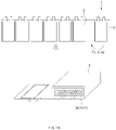
- the stack and folding type electrode assembly 1 may be manufactured by folding a folding separator 2 from one side after a plurality of unit cells 3 are placed side by side on the folding separator 2 at a predetermined interval.
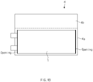
- FIG. 1b shows a state in which the electrode assembly is embedded in the pouch
- the electrode assembly 1 is embedded in a body part 4a of the pouch 4, and then, an electrolyte is injected into the body part 4a so that the electrode assembly is impregnated in the electrolyte.
- the pouch is sealed by bonding a portion, into which the electrode assembly 1 is inserted, through thermal fusion.
- a charging/discharging process is performed to activate the battery.
- degassing is performed to discharge the gas generated therein.
- a predetermined pressure is vertically applied to the body part 4a to allow the gas generated in the body part 4a to move to a gas pocket part 4b, and simultaneously, a gas inhaler is inserted into the gas pocket part 4b to inhale the gas.
- the electrode assembly 1 manufactured in the stack and folding manner has a structure in which a long side facing the gas pocket part 4b is closed, but a short side perpendicular to the gas pocket part 4b is opened.
- efficiency of the degassing process is deteriorated because the gas generated in the body part 4a does not move smoothly to the gas pocket part 4b.
- the gas is not normally discharged to remain in the body part 4a, swelling, lithium precipitation, etc. may occur, and also, the electrode assembly is deformed and deteriorated in performance.
- a main object of the present invention for solving the above problems is to provide a method for manufacturing a secondary battery, which is capable of smoothly discharging a gas during an activation process and a degassing process, and a secondary battery to which the above manufacturing method is capable of being applied.
- the present invention for achieving the above object provides a degassing method for a secondary battery and a secondary battery to which the degassing method is applied.
- a method for degassing a secondary battery comprises: an electrode assembly providing step (S10) of manufacturing an electrode assembly having a stacked structure in which a negative electrode, an individual layer of a separator, a positive electrode, and an individual layer of the separator are repeated by alternately inserting the positive electrode and the negative electrode between the adjacent individual layers of the separator, wherein fold lines are formed on the separator at a predetermined interval, and the separator is folded in a zigzag shape along a vertical direction by the fold lines to form the plurality of individual layers; an insertion step (S20) of inserting the electrode assembly into a pouch; and a degassing step (S30) of discharging a gas from the pouch, wherein, in the electrode assembly providing step (S10), each of the positive electrode and the negative electrode is manufactured in a square shape so that remaining three sides except for one side facing the fold lines among four sides formed along a circumference thereof are opened.
- a negative electrode tab protruding from the negative electrode and a positive electrode tab protruding from the positive electrode may be disposed to protrude from the separator in opposite directions.
- each of the positive electrode and the negative electrode may be formed in a rectangular shape having two short sides, each of which has a relatively short length, and two long sides, each of which has a relatively long length, and each of the fold lines of the separator may have a length greater than that of the short side of each of the positive electrode and the negative electrode and less than that of the long side of each of the positive electrode and the negative electrode, wherein one of the short sides of each of the positive electrode and the negative electrode may be inserted between the individual layers of the separator to face the fold line of the separator so that all both the long sides of each of the positive electrode and the negative electrode are opened.
- a negative electrode tab protruding from the negative electrode and a positive electrode tab protruding from the positive electrode may be disposed to protrude from the separator in the same direction.
- each of the positive electrode and the negative electrode may be formed in a rectangular shape having two short sides, each of which has a relatively short length, and two long sides, each of which has a relatively long length, and each of the fold lines of the separator may have a length greater than that of the long side of each of the positive electrode and the negative electrode, wherein one of the long sides of each of the positive electrode and the negative electrode may be inserted between the individual layers of the separator to face the fold line of the separator so that all both the short sides of each of the positive electrode and the negative electrode are opened.
- the pouch may comprise a body part into which the electrode assembly is inserted and a gas pocket part communicating with the body part and extending from one side of the body part, wherein, in the insertion step (S20), one of the long sides of each of the positive electrode and the negative electrode may be inserted to face the gas pocket part.
- the negative electrode may be opened toward the gas pocket part at the long sides of the electrode assembly, which face the gas pocket part.
- the electrode assembly providing step (S10) may comprise: a support bar insertion step (S11) of inserting a plurality of support bars so that one surface and the other surface of the separator are alternately disposed at a predetermined interval; an individual layer formation step (S12) of allowing the support bar disposed to face the one surface of the separator and the support bar disposed to face the other surface of the separator to move in directions crossing each other so as to form the individual layers on the separator; an electrode insertion step (S13) of alternately inserting the positive electrode and the negative electrode between the individual layers of the separator adjacent to each other; and a pulling step (S14) of pulling both ends of the separator at a predetermined pressure in the state in which the electrodes are inserted.
- the present invention may additionally provide a secondary battery to which the degassing method as described above is capable of being applied.
- a secondary battery comprises: an electrode assembly having a stacked structure in which a negative electrode, an individual layer of a separator, a positive electrode, and an individual layer of the separator are repeated by alternately inserting the positive electrode and the negative electrode between the adjacent individual layers of the separator, wherein fold lines are formed on the separator at a predetermined interval, and the separator is folded in a zigzag shape along a vertical direction by the fold lines to form the plurality of individual layers; and a pouch comprising a body part into which the electrode assembly is inserted and a gas pocket part communicating with the body part and extending from one side of the body part, wherein each of the positive electrode and the negative electrode is manufactured in a square shape so that remaining three sides except for one side facing the fold lines among four sides formed along a circumference thereof are opened, and the electrode assembly is inserted into the pouch so that one of the opened sides of the positive electrode or the opened sides of the negative electrode faces the gas pocket part.
- the electrode assembly may be inserted into the pouch so that the opened sides of the negative electrode face the gas pocket part.
- the gas pocket part may be cut and separated from the body part.
- the negative electrode and the positive electrode may be manufactured in the square shape, but the remaining three sides except for one side may be opened in the separator so that gas is efficiently discharged.
- the gas since at least one of the negative electrode or the positive electrode has the opened long side to face the gas pocket part of the pouch, the gas may more quickly move to the gas pocket part.
- the long side of the negative electrode having the relatively large gas discharge amount in the positive electrode and the negative electrode may be opened to more improve the gas discharge efficiency.
- the present invention relates to a method of manufacturing a secondary battery, in which a gas is smoothly discharged during an activation process of performing initial charging and discharging and a degassing process, and a secondary battery to which the manufacturing method is applied.
- a gas is smoothly discharged during an activation process of performing initial charging and discharging and a degassing process, and a secondary battery to which the manufacturing method is applied.
- a manufacturing method comprises an electrode assembly providing step (S10), an insertion step (S20), and a degassing step (S30).
- the insertion step (S20) is a step of inserting an electrode assembly into a pouch
- the degassing step (S30) is a step of inhaling a gas moving to a gas pocket part to the outside.
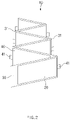
- FIGS. 2 and 3 are perspective and side views illustrating a state of being disposed between individual layers of a separator 30 when manufactured in an electrode assembly providing step according to the present invention, i.e., when a positive electrode tab 21 and a negative electrode tab 41 are manufactured to protrude in opposite directions
- the separator 30 is provided by a predetermined length, and also, the separator 30 is provided to be folded so as to form fold lines 31 with a size of a positive electrode 20 and a negative electrode 40 or an interval that is slightly greater than the size therebetween.
- the separator 30 may be folded in a zigzag shape along a vertical direction by the fold lines 31 formed at a predetermined interval to form a plurality of individual layers.
- the positive electrode 20 when the positive electrode 20 is inserted between an individual layer of the separator 30, which is disposed at the lowermost side, and a second individual layer above on the lowermost individual layer, the negative electrode 40 is inserted between the second individual layer and a third individual layer, and the positive electrode 20 is inserted again between the third individual layer and a fourth individual layer.
- the positive electrode 20 and the negative electrode 40 are alternately inserted in this manner to provide the electrode assembly 10 having a stacked structure in which the negative electrode 40, the individual layer of the separator 30, the positive electrode 20, and the individual layer of the separator 30 are repeated.
- each of the negative electrode 40 and the positive electrode 20 are manufactured in a square shape, and since remaining three sides except for one side facing the fold line 31 among four sides formed along a circumference of the electrode assembly 10 are disposed at opened portions of the separator 30, the sides are opened to be exposed.
- each of the positive electrode 20 and the negative electrode 40 has a rectangular shape having two short sides, each of which has a relatively short length, and two long sides, each of which has a relatively long length.
- the separator 30 is provided so that the fold line 31 has a length greater than that of the short sides of each of the positive electrode 20 and the negative electrode 40 and less than that of the long sides of each of the positive electrode 20 and the negative electrode 40.
- one of the short sides of the positive electrode 20 and the negative electrode 40 is inserted between the individual layers of the separator to face the fold line of the separator so that both the long sides of the positive electrode 20 and the negative electrode 40 are opened.
- each of the positive electrode 20 and the negative electrode 40 has the rectangular shape
- each of the positive electrode 20 and the negative electrode 40 may have a square shape of which four sides have the same length.
- each of the fold lines may have the same length as each of the sides of the positive electrode 20 and the negative electrode 40.
- FIG. 4 that illustrates a see-through state when the electrode assembly 10 according to Embodiment 1 is inserted into a body part 50a of a pouch 50
- openings of the separator 30 are formed in all both the long sides of the positive electrode 20 and the negative electrode 40 (since both the long sides of the positive electrode and both the long sides of the negative electrode are not covered by the separator)
- a gas may more smoothly move to the gas pocket part 50b of the pouch 50. That is to say, since the openings of the separator 30 are formed toward the gas pocket part at the sides of the positive electrode 20 and the negative electrode 40, which face the gas pocket part, the gas may be more smoothly move.
- a positive electrode tab 21 and a negative electrode tab 41 may be manufactured to protrude in opposite directions, but the positive electrode tab 21 and the negative electrode tab 41 may also be manufactured to protrude in the same direction.
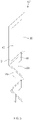
- FIGS. 5 and 6 are perspective and side views illustrating a state in which the positive electrode tab 21 and the negative electrode tab 41 are disposed between individual layers of a separator 30 to protrude in the same direction when manufactured in an electrode assembly providing step
- the positive electrode tab 21 and the negative electrode tab 41 may be disposed in the same direction according to a direction in which the positive electrode 20 and the negative electrode 40 are inserted between the adjacent individual layers of the separator 30.
- each of a positive electrode 20 and a negative electrode 40 has a rectangular shape having two short sides, each of which has a relatively short length, and two long sides, each of which has a relatively long length.
- each of the positive electrode 20 and the negative electrode 40 has the rectangular shape, each of the positive electrode 20 and the negative electrode 40 may have a square shape of which four sides have the same length.
- the separator 30 is configured so that a fold line 31 has a length greater than each of the long sides of the positive electrode 20 and the negative electrode 40, and one of the long sides of the positive electrode 20 and the negative electrode 40 is inserted between the individual layers of the separator 30 to face the fold line 31 of the separator 30 so that all both short sides of the positive electrode 20 and the negative electrode 40 are opened.
- the fold line 31 of the separator 30 has a length that is equal to or greater than that of each of the sides of the negative electrode 40 and the positive electrode 20.
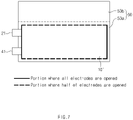
- FIG. 7 that illustrates a see-through state when an electrode assembly 10' according to Embodiment 2 is inserted into a body part 50a of a pouch 50
- openings of a separator 30 are formed in all both short sides of a positive electrode 20 and a negative electrode 40, but one of the positive electrode 20 and the negative electrode 40 is covered by a fold line 31 of the separator 30 in a direction of a gas pocket part 50b at both the long sides.
- the openings of the separator 30 are formed in a side, on which the electrode tab is disposed, and a side facing the side on which the electrode tab is disposed, but one of the positive electrode 20 and the negative electrode 40 is covered by the fold line 31 in the direction of the gas pocket part 50b at two sides perpendicular to the side, on which the electrode tab is disposed.
- FIG. 8 which illustrates a state in which one of the long sides of the negative electrode 40 is opened, and the opened long side is disposed toward the gas pocket part 50b of the pouch 50
- a direction indicated by a 'gas generation arrow' is a direction toward the gas pocket part when the electrode assembly according to Embodiment 2 is inserted into a body part.
- the negative electrode 40 is opened in the direction toward the gas pocket part 50b, but the opposite side thereof is blocked by the fold line 31 of the separator 30.
- the positive electrode 20 is blocked in the direction toward the gas pocket part 50b, but the opposite side is opened.
- the pouch 50 has a structure that extends from the body part 50a, into which the electrode assembly 10' is inserted, to one side of the gas pocket part 50b that communicates with the body part 50a and extends to one side of the body part 50a.
- the electrode assembly 10' manufactured as described above may be selectively mounted in the direction, in which the negative electrode 40 is opened, toward the gas pocket part 50b or in the direction, in which the positive electrode 20 is opened, toward the gas pocket part 50b.
- the electrode assembly 10' having the same configuration as in Embodiments 2 is provided in the electrode assembly providing step (S10), in the insertion step (S20) of the degassing method according to the present invention, it is more preferable that the electrode assembly 10' is inserted into the body part 50a in the direction, in which the negative electrode 20 is opened toward the gas pocket part 50b at the long side of the electrode assembly 10' (or at one side at which one of the negative electrode and the positive electrode is opened, and the other is blocked in the case of the square shape) when compared to the opposite case.
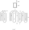
- the electrode assembly providing step (S10) detailed steps of interposing the negative electrode 40 and the positive electrode 20 between the individual layers of the separator 30 may be additionally provided. That is, referring to FIG. 9 , which simplifies and illustrates states in which the electrode assembly is manufactured in the electrode assembly providing step (S10) according to the present invention, when the separator 30 is provided by a predetermined length, a support bar insertion step (S11) of inserting a plurality of support bars 60 so that one surface and the other surface of the separator 30 are alternately disposed at a predetermined interval is performed.
- an individual layer formation step (S12) of allowing the support bar 60 disposed to face the one surface of the separator 30 and the support bar 60 disposed to face the other surface of the separator 30 to move in directions crossing each other, thereby forming individual layers on the separator 30 is performed.
- an electrode insertion step (S13) of alternately inserting the positive electrode 20 and the negative electrode 40 between the individual layers of the separator 30 adjacent to each other is performed.
- a pulling step (S14) of pulling both ends of the separator 30 at a predetermined pressure in the state in which the electrodes (the positive and negative electrodes) are inserted is performed, and thus, the separator 30 has a structure in which the negative electrode 40 and the positive electrode 20 are stacked in the state in which predetermined tension is applied. Finally, both ends of the separator 30 is cut at an appropriate position.
- the negative electrode and the positive electrode may be manufactured in a rectangular shape, but the remaining three sides except for one side may be opened in the separator so that gas is efficiently discharged.
- At least one of the negative electrode 40 or the positive electrode 20 may be disposed to face the gas pocket part 50b of the pouch 50 so that the gas more quickly moves to the gas pocket part 50b.
- the long side of the negative electrode 40 having a relatively large gas discharge amount in the positive electrode 20 and the negative electrode 40 may be opened to more improve gas discharge efficiency.
- positive active material slurry was manufactured by adding 40 parts by weight of solid at a ratio of 90:5.5 (wt%) based on parts by weight, at which a ternary active material (Li(Ni 0 . 5 Mn 0 . 3 Co 0 . 2 )O 2 ) as a positive electrode active material, carbon black as a conductive material, polyvinylidene fluoride (PVDF) as a binder are mixed in 100 parts by weight of N-methyl-2-pyrrolidone (NMP).
- the positive electrode active material slurry was applied to a positive electrode collector (aluminum thin film) 20a having a thickness of 100 ⁇ m and then was dried. Then, roll press was performed to manufacture the positive electrode.
- negative active material slurry was manufactured by adding 100 parts by weight of solid at a ratio of 90:5:2:3 (wt%) based on parts by weight, at which natural graphite and SiO x (0 ⁇ x ⁇ 1) as negative active materials, PVDF as a binder, and carbon black as a conductive material are mixed in 100 parts by weight of NMP.
- the negative electrode active material slurry was applied to a negative electrode collector (copper thin film) 40a having a thickness of 90 ⁇ m and then was dried. Then, roll press was performed to manufacture the negative electrode.
- Ethylene carbonate (EC) and ethyl methyl carbonate (EMC) were mixed at a ratio of 30:70 (vol%) based on volume percentage and then dissolved so that LiPF6 has a concentration of 1M to manufacture an organic mixture. Then, 1 part by weight of vinylene carbonate (VC) and 1 part by weight of 1,3-propenesultone (PS) were added to manufacture the electrolyte.
- EC Ethylene carbonate
- EMC ethyl methyl carbonate
- An electrode assembly having the same structure as in Embodiment 1 was manufactured using a negative electrode 40 and a positive electrode 20, which are manufactured in the same manner as described above, and after the electrode assembly was embedded in a body part 50a of a pouch, the above-described electrolyte was injected.
- An electrode assembly having the same structure as in Embodiment 2 was manufactured using a negative electrode 40 and a positive electrode 20, which are manufactured in the same manner as described above, and after the electrode assembly was embedded in a pouch, the above-described electrolyte was injected. However, the electrode assembly was inserted into a body part 50a so that an electrode that is opened in a direction toward a gas pocket part 50b is the positive electrode 20, and the negative electrode 40 is closed in the direction toward the gas pocket part 50b.
- An electrode assembly having the same structure as in Embodiment 2 was manufactured using a negative electrode 40 and a positive electrode 20, which are manufactured in the same manner as described above, and after the electrode assembly was embedded in a pouch, the above-described electrolyte was injected. However, the electrode assembly was inserted into a body part 50a so that an electrode that is opened in a direction toward a gas pocket part 50b is the negative electrode 40, and the positive electrode 20 is closed in the direction toward the gas pocket part 50b.
- a stack and folding type electrode assembly was manufactured using a negative electrode and a positive electrode in the same manner as described above. Here, tabs of the positive electrode and the negative electrode were disposed in different directions. After the electrode assembly is embedded in a pouch 50, an electrolyte as described above was injected.
- a stack and folding type electrode assembly was manufactured using a negative electrode and a positive electrode in the same manner as described above. Here, tabs of the positive electrode and the negative electrode were disposed in the same direction. After the electrode assembly is embedded in a pouch 50, an electrolyte as described above was injected.
- Table 1 below shows experimental data.
- Type of electrode assembly Position of electrode tab Whether opened or not between positive electrode and gas pocket Whether opened or not between negative electrode and gas pocket Amount of gas in gas pocket part Lithium precipitat ion Discharge capacity compared to Comparativ e
- Example 1 Capacity retention rate
- Manufacturin g Example 1 Structure according to Embodiment 1 Bidirection al Open Open 107.2 None 102.1 93.6 Manufacturing
- Example 2 Structure according to Embodiment 2 Unidirectional Open Close 105.4 Small amount generation 101.4 93.1 Manufacturin g
- Example 3 Structure according to Embodimen t 3 Unidirectio nal Close Open 110.3 None 103.5 95.7 Comparative Example 1 Stack and folding structure according to related art Bidirection al Close Close 100.0 Large amount generatio n 100 87.5 Comparative Example 2 Stack and folding structure according to related art Unidirectio nal Close Close 100.0 Large amount generatio n 100 89.2
- each secondary battery was disassembled to observe whether lithium is precipitated.
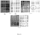
- FIG. 10 is a photograph illustrating a state ⁇ i> of a disassembled negative electrode of a secondary battery manufactured according to Manufacturing Example 1 of the present invention and a separator facing the negative electrode, a state ⁇ ii> in which a disassembled negative electrode of a secondary battery manufactured according to Manufacturing Example 2 of the present invention and a separator facing the negative electrode, and a state ⁇ iii> in which a disassembled negative electrode of a secondary battery, in which an electrode assembly according to a related art is mounted, and a separator facing the negative electrode.
- the lithium precipitation affects the discharge capacity.
- the initial discharge capacity is not substantially different, but the difference is widened in the capacity retention rate after the charging and discharging are performed 100 times. That is, the case of Comparative Example 1, in which the gas remains in the body part 50a exhibits a lower capacity retention rate compared to Manufacturing Example 1, and the case of Comparative Example 2 exhibits a lower capacity retention rate compared to Manufacturing Examples 2 and 3. It is seen that the capacity retention rate is greater in an order (order of Manufacturing Example 3 and Manufacturing Example 2), in which the gas is discharged more smoothly.
Landscapes
- Chemical & Material Sciences (AREA)
- Chemical Kinetics & Catalysis (AREA)
- Electrochemistry (AREA)
- General Chemical & Material Sciences (AREA)
- Engineering & Computer Science (AREA)
- Manufacturing & Machinery (AREA)
- Secondary Cells (AREA)
Abstract
Description
- The present application claims the benefit of the priority of
Korean Patent Application No. 10-2020-0056068, filed on May 11, 2020 - The present invention relates to a method for manufacturing a secondary battery and a secondary battery that is capable of being applied to the manufacturing method, and more particularly, to a method for manufacturing a secondary battery, which is disposed toward a gas pocket part of a pouch, in which an electrode has as many openings as possible, to improve a gas discharge effect, and a secondary battery to which the manufacturing method is capable of being applied.
- Recently, with the rapid development of the electric, electronic, telecommunication and computer industries, the demand for high performance and high safety batteries is gradually increasing. Particularly, as electronic devices are becoming more compact, thinner and lighter, the demands for miniaturization and thinning of batteries is gradually increasing. In response to these demands, a lithium secondary battery with a high energy density is drawing the most attention.
- Lithium batteries have advantages of long lifespan and large capacity and are widely used in portable electronic devices. The lithium batteries comprise lithium metal batteries and lithium ion batteries, which use a liquid electrolyte, and lithium polymer batteries using a polymer solid battery depending on types of electrolytes.
- In addition, lithium secondary batteries are classified into a prismatic battery using a prismatic can, a cylindrical battery using a cylindrical can, and a pouch-type battery using a pouch according to types of exteriors that seal an electrode assembly.
- In the pouch-type battery, the pouch comprises a body part, in which an electrode assembly and an electrolyte are embedded, and a gas pocket part that is expanded to one side from the body part and is opened to allow a gas to be introduced and discharged. The gas pocket part is a portion at which the gas is collected during an activation process of performing initial charging and discharging and a degassing process performed after the activation process. When the degassing is completed, the portion may be cut to be removed, and a cut portion between the gas pocket part and the body part is sealed by applying heat and a pressure. Alternatively, sealing is performed by the heat and pressure before the body part and the gas pocket part are cut, and then cutting is performed after the sealing.
- Also, as is known, the electrode assembly inserted into the pouch-type battery is classified into a winding type electrode assembly in which the separator is stacked between the negative electrode and the positive electrode and then wound to manufacture an electrode assembly, a stacking type electrode assembly in which each of a negative electrode and a positive electrode is cut by a desired width and length, and then, the negative electrode, the separator, the positive electrode are repeatedly stacked to form an electrode assembly, and a stack and folding type electrode assembly in which unit cells are placed parallel to each other on a folding separator and then folded from one side to manufacture an electrode assembly.
- Referring to
FIG. 1a , which shows a state in which the stack and folding type electrode assembly is manufactured, the stack and foldingtype electrode assembly 1 may be manufactured by folding afolding separator 2 from one side after a plurality ofunit cells 3 are placed side by side on thefolding separator 2 at a predetermined interval. - However, in the case of this structure, only a side, to which an electrode tab protrudes, and an opposite side are opened (only one side of each of a negative electrode and a positive electrode is opened), and the folded side surface is closed by the
folding separator 2. That is, based on the rectangular electrode assembly, a short side at which the electrode tab protrudes is opened, but a long side perpendicular to the short side is closed. - Also, as illustrated in
FIG. 1b that shows a state in which the electrode assembly is embedded in the pouch, theelectrode assembly 1 is embedded in abody part 4a of thepouch 4, and then, an electrolyte is injected into thebody part 4a so that the electrode assembly is impregnated in the electrolyte. When the electrolyte is injected as described above, the pouch is sealed by bonding a portion, into which theelectrode assembly 1 is inserted, through thermal fusion. - Also, after an aging process is performed for stabilization, a charging/discharging process is performed to activate the battery. During the charging and discharging process, since a gas is generated inside the pouch, degassing is performed to discharge the gas generated therein.
- In the degassing process, after inserting the
body part 4a between an upper mold (not shown) and a lower mold (not shown), a predetermined pressure is vertically applied to thebody part 4a to allow the gas generated in thebody part 4a to move to agas pocket part 4b, and simultaneously, a gas inhaler is inserted into thegas pocket part 4b to inhale the gas. - After the degassing process is performed, a portion to be cut between the
gas pocket part 4b and thebody part 4a is sealed, and thegas pocket part 4b is cut and discarded to manufacture a secondary battery. - As illustrated in
FIG. 1b , as described above, theelectrode assembly 1 manufactured in the stack and folding manner has a structure in which a long side facing thegas pocket part 4b is closed, but a short side perpendicular to thegas pocket part 4b is opened. Thus, there is a problem in that efficiency of the degassing process is deteriorated because the gas generated in thebody part 4a does not move smoothly to thegas pocket part 4b. - Also, if the gas is not normally discharged to remain in the
body part 4a, swelling, lithium precipitation, etc. may occur, and also, the electrode assembly is deformed and deteriorated in performance. - Accordingly, a main object of the present invention for solving the above problems is to provide a method for manufacturing a secondary battery, which is capable of smoothly discharging a gas during an activation process and a degassing process, and a secondary battery to which the above manufacturing method is capable of being applied.
- The present invention for achieving the above object provides a degassing method for a secondary battery and a secondary battery to which the degassing method is applied.
- A method for degassing a secondary battery according to the present invention comprises: an electrode assembly providing step (S10) of manufacturing an electrode assembly having a stacked structure in which a negative electrode, an individual layer of a separator, a positive electrode, and an individual layer of the separator are repeated by alternately inserting the positive electrode and the negative electrode between the adjacent individual layers of the separator, wherein fold lines are formed on the separator at a predetermined interval, and the separator is folded in a zigzag shape along a vertical direction by the fold lines to form the plurality of individual layers; an insertion step (S20) of inserting the electrode assembly into a pouch; and a degassing step (S30) of discharging a gas from the pouch, wherein, in the electrode assembly providing step (S10), each of the positive electrode and the negative electrode is manufactured in a square shape so that remaining three sides except for one side facing the fold lines among four sides formed along a circumference thereof are opened.
- In the electrode assembly providing step (S10), a negative electrode tab protruding from the negative electrode and a positive electrode tab protruding from the positive electrode may be disposed to protrude from the separator in opposite directions.
- In the electrode assembly providing step (S10), each of the positive electrode and the negative electrode may be formed in a rectangular shape having two short sides, each of which has a relatively short length, and two long sides, each of which has a relatively long length, and each of the fold lines of the separator may have a length greater than that of the short side of each of the positive electrode and the negative electrode and less than that of the long side of each of the positive electrode and the negative electrode, wherein one of the short sides of each of the positive electrode and the negative electrode may be inserted between the individual layers of the separator to face the fold line of the separator so that all both the long sides of each of the positive electrode and the negative electrode are opened.
- In the electrode assembly providing step (S10), a negative electrode tab protruding from the negative electrode and a positive electrode tab protruding from the positive electrode may be disposed to protrude from the separator in the same direction.
- In the electrode assembly providing step (S10), each of the positive electrode and the negative electrode may be formed in a rectangular shape having two short sides, each of which has a relatively short length, and two long sides, each of which has a relatively long length, and each of the fold lines of the separator may have a length greater than that of the long side of each of the positive electrode and the negative electrode, wherein one of the long sides of each of the positive electrode and the negative electrode may be inserted between the individual layers of the separator to face the fold line of the separator so that all both the short sides of each of the positive electrode and the negative electrode are opened.
- The pouch may comprise a body part into which the electrode assembly is inserted and a gas pocket part communicating with the body part and extending from one side of the body part, wherein, in the insertion step (S20), one of the long sides of each of the positive electrode and the negative electrode may be inserted to face the gas pocket part.
- In the insertion step (S20), the negative electrode may be opened toward the gas pocket part at the long sides of the electrode assembly, which face the gas pocket part.
- The electrode assembly providing step (S10) may comprise: a support bar insertion step (S11) of inserting a plurality of support bars so that one surface and the other surface of the separator are alternately disposed at a predetermined interval; an individual layer formation step (S12) of allowing the support bar disposed to face the one surface of the separator and the support bar disposed to face the other surface of the separator to move in directions crossing each other so as to form the individual layers on the separator; an electrode insertion step (S13) of alternately inserting the positive electrode and the negative electrode between the individual layers of the separator adjacent to each other; and a pulling step (S14) of pulling both ends of the separator at a predetermined pressure in the state in which the electrodes are inserted.
- Furthermore, the present invention may additionally provide a secondary battery to which the degassing method as described above is capable of being applied.
- A secondary battery according to the present invention comprises: an electrode assembly having a stacked structure in which a negative electrode, an individual layer of a separator, a positive electrode, and an individual layer of the separator are repeated by alternately inserting the positive electrode and the negative electrode between the adjacent individual layers of the separator, wherein fold lines are formed on the separator at a predetermined interval, and the separator is folded in a zigzag shape along a vertical direction by the fold lines to form the plurality of individual layers; and a pouch comprising a body part into which the electrode assembly is inserted and a gas pocket part communicating with the body part and extending from one side of the body part, wherein each of the positive electrode and the negative electrode is manufactured in a square shape so that remaining three sides except for one side facing the fold lines among four sides formed along a circumference thereof are opened, and the electrode assembly is inserted into the pouch so that one of the opened sides of the positive electrode or the opened sides of the negative electrode faces the gas pocket part.
- The electrode assembly may be inserted into the pouch so that the opened sides of the negative electrode face the gas pocket part.
- After a gas is collected in the gas pocket part, the gas pocket part may be cut and separated from the body part.
- According to the present invention having the configuration as described above, in the electrode assembly, the negative electrode and the positive electrode may be manufactured in the square shape, but the remaining three sides except for one side may be opened in the separator so that gas is efficiently discharged.
- In addition, according to the present invention, since at least one of the negative electrode or the positive electrode has the opened long side to face the gas pocket part of the pouch, the gas may more quickly move to the gas pocket part.
- In particular, the long side of the negative electrode having the relatively large gas discharge amount in the positive electrode and the negative electrode may be opened to more improve the gas discharge efficiency.
-
-
FIG. 1a is a view illustrating a state in which a stack and folding type electrode assembly is manufactured. -
FIG. 1b is a plan view illustrating a see-through state in which the electrode assembly ofFIG. 1a is embedded in a pouch. -
FIG. 2 is a view illustrating a state of being disposed between individual layers of a separator when manufactured in an electrode assembly providing step according to the present invention, i.e., when a positive electrode tab and a negative electrode tab are manufactured to protrude in opposite directions. -
FIG. 3 is a side view illustrating a state when a negative electrode and a positive electrode are disposed between the individual layers of the separator as illustrated inFIG. 2 . -
FIG. 4 is a plan view illustrating a see-through state when the electrode assembly stacked as illustrated inFIGS. 2 and3 is inserted into a body part of the pouch. -
FIG. 5 is a view illustrating a state of being disposed between the individual layers of the separator when manufactured in the electrode assembly providing step according to the present invention, i.e., when the positive electrode tab and the negative electrode tab are manufactured to protrude in the same direction. -
FIG. 6 is a side view illustrating a state when the negative electrode and the positive electrode are disposed between the individual layers of the separator as illustrated inFIG. 5 . -
FIG. 7 is a plan view illustrating a see-through state when the electrode assembly stacked as illustrated inFIGS. 5 and6 is inserted into the body part of the pouch. -
FIG. 8 is a view illustrating a state in which one of sides of the negative electrode is opened, and the opened corresponding side is disposed toward a gasket part of the pouch. -
FIG. 9 is a simplified view illustrating states in which the electrode assembly is manufactured in the electrode assembly providing step (S10) according to the present invention. -
FIG. 10 is a photograph illustrating a state <i> of a disassembled negative electrode of a secondary battery manufactured according to Manufacturing Example 1 of the present invention and a separator facing the negative electrode, a state <ii> in which a disassembled negative electrode of a secondary battery manufactured according to Manufacturing Example 2 of the present invention and a separator facing the negative electrode, and a state <iii> in which a disassembled negative electrode of a secondary battery, in which an electrode assembly according to a related art is mounted, and a separator facing the negative electrode, i.e., photographs illustrating respective states in which lithium precipitation occurs. - Hereinafter, preferred embodiments of the present invention will be described in detail with reference to the accompanying drawings in such a manner that the technical idea of the present invention may easily be carried out by a person with ordinary skill in the art to which the invention pertains. The present invention may, however, be embodied in different forms and should not be construed as limited to the embodiments set forth herein.
- In order to clearly illustrate the present invention, parts that are not related to the description are omitted, and the same or similar components are denoted by the same reference numerals throughout the specification.
- Also, terms or words used in this specification and claims should not be restrictively interpreted as ordinary meanings or dictionary-based meanings, but should be interpreted as meanings and concepts conforming to the scope of the present invention on the basis of the principle that an inventor can properly define the concept of a term to describe and explain his or her invention in the best ways.
- The present invention relates to a method of manufacturing a secondary battery, in which a gas is smoothly discharged during an activation process of performing initial charging and discharging and a degassing process, and a secondary battery to which the manufacturing method is applied. Hereinafter, the present invention will be described in more detail with reference to the accompanying drawings.
- A manufacturing method according to the present invention comprises an electrode assembly providing step (S10), an insertion step (S20), and a degassing step (S30). The insertion step (S20) is a step of inserting an electrode assembly into a pouch, and the degassing step (S30) is a step of inhaling a gas moving to a gas pocket part to the outside. Here, since the steps are performed in various manners, detailed descriptions with respect to a specific manner will be omitted.
- Referring to
FIGS. 2 and3 which are perspective and side views illustrating a state of being disposed between individual layers of aseparator 30 when manufactured in an electrode assembly providing step according to the present invention, i.e., when apositive electrode tab 21 and anegative electrode tab 41 are manufactured to protrude in opposite directions, in the electrode assembly providing step according to this embodiment, theseparator 30 is provided by a predetermined length, and also, theseparator 30 is provided to be folded so as to formfold lines 31 with a size of apositive electrode 20 and anegative electrode 40 or an interval that is slightly greater than the size therebetween. - That is, as illustrated in the drawings, the
separator 30 may be folded in a zigzag shape along a vertical direction by the fold lines 31 formed at a predetermined interval to form a plurality of individual layers. - Also, as illustrated in
FIG. 3 , when thepositive electrode 20 is inserted between an individual layer of theseparator 30, which is disposed at the lowermost side, and a second individual layer above on the lowermost individual layer, thenegative electrode 40 is inserted between the second individual layer and a third individual layer, and thepositive electrode 20 is inserted again between the third individual layer and a fourth individual layer. For example, thepositive electrode 20 and thenegative electrode 40 are alternately inserted in this manner to provide theelectrode assembly 10 having a stacked structure in which thenegative electrode 40, the individual layer of theseparator 30, thepositive electrode 20, and the individual layer of theseparator 30 are repeated. - In the
electrode assembly 10, each of thenegative electrode 40 and thepositive electrode 20 are manufactured in a square shape, and since remaining three sides except for one side facing thefold line 31 among four sides formed along a circumference of theelectrode assembly 10 are disposed at opened portions of theseparator 30, the sides are opened to be exposed. - As illustrated in
FIGS. 2 and3 , each of thepositive electrode 20 and thenegative electrode 40 has a rectangular shape having two short sides, each of which has a relatively short length, and two long sides, each of which has a relatively long length. Theseparator 30 is provided so that thefold line 31 has a length greater than that of the short sides of each of thepositive electrode 20 and thenegative electrode 40 and less than that of the long sides of each of thepositive electrode 20 and thenegative electrode 40. Also, one of the short sides of thepositive electrode 20 and thenegative electrode 40 is inserted between the individual layers of the separator to face the fold line of the separator so that both the long sides of thepositive electrode 20 and thenegative electrode 40 are opened. - For reference, although each of the
positive electrode 20 and thenegative electrode 40 has the rectangular shape, each of thepositive electrode 20 and thenegative electrode 40 may have a square shape of which four sides have the same length. Here, when thefold line 31 of theseparator 30, which is a portion folded at ends of thepositive electrode 20 and thenegative electrode 40, is folded, each of the fold lines may have the same length as each of the sides of thepositive electrode 20 and thenegative electrode 40. However, it is preferable that each of the fold lines 31 has a length greater than that of each of thepositive electrode 20 and thenegative electrode 40 to prevent the electrode assembly from being biased to be exposed. - Therefore, as illustrated in
FIG. 4 that illustrates a see-through state when theelectrode assembly 10 according toEmbodiment 1 is inserted into abody part 50a of apouch 50, when theelectrode assembly 10 according toEmbodiment 1 is inserted into thepouch 50, openings of theseparator 30 are formed in all both the long sides of thepositive electrode 20 and the negative electrode 40 (since both the long sides of the positive electrode and both the long sides of the negative electrode are not covered by the separator), a gas may more smoothly move to thegas pocket part 50b of thepouch 50. That is to say, since the openings of theseparator 30 are formed toward the gas pocket part at the sides of thepositive electrode 20 and thenegative electrode 40, which face the gas pocket part, the gas may be more smoothly move. - As illustrated in
FIGS. 2 and3 , apositive electrode tab 21 and anegative electrode tab 41 may be manufactured to protrude in opposite directions, but thepositive electrode tab 21 and thenegative electrode tab 41 may also be manufactured to protrude in the same direction. - That is, as illustrated in
FIGS. 5 and6 , which are perspective and side views illustrating a state in which thepositive electrode tab 21 and thenegative electrode tab 41 are disposed between individual layers of aseparator 30 to protrude in the same direction when manufactured in an electrode assembly providing step, thepositive electrode tab 21 and thenegative electrode tab 41 may be disposed in the same direction according to a direction in which thepositive electrode 20 and thenegative electrode 40 are inserted between the adjacent individual layers of theseparator 30. - As illustrated in
FIGS. 5 and6 , even in an electrode assembly 10' according to this embodiment, each of apositive electrode 20 and anegative electrode 40 has a rectangular shape having two short sides, each of which has a relatively short length, and two long sides, each of which has a relatively long length. - As mentioned above, although each of the
positive electrode 20 and thenegative electrode 40 has the rectangular shape, each of thepositive electrode 20 and thenegative electrode 40 may have a square shape of which four sides have the same length. - However, unlike
Embodiment 1, theseparator 30 is configured so that afold line 31 has a length greater than each of the long sides of thepositive electrode 20 and thenegative electrode 40, and one of the long sides of thepositive electrode 20 and thenegative electrode 40 is inserted between the individual layers of theseparator 30 to face thefold line 31 of theseparator 30 so that all both short sides of thepositive electrode 20 and thenegative electrode 40 are opened. When each of thenegative electrode 40 and thepositive electrode 20 has a square shape, thefold line 31 of theseparator 30 has a length that is equal to or greater than that of each of the sides of thenegative electrode 40 and thepositive electrode 20. - Therefore, as illustrated in
FIG. 7 that illustrates a see-through state when an electrode assembly 10' according toEmbodiment 2 is inserted into abody part 50a of apouch 50, when the electrode assembly 10' according toEmbodiment 2 is inserted into thepouch 50, openings of aseparator 30 are formed in all both short sides of apositive electrode 20 and anegative electrode 40, but one of thepositive electrode 20 and thenegative electrode 40 is covered by afold line 31 of theseparator 30 in a direction of agas pocket part 50b at both the long sides. That is to say, the openings of theseparator 30 are formed in a side, on which the electrode tab is disposed, and a side facing the side on which the electrode tab is disposed, but one of thepositive electrode 20 and thenegative electrode 40 is covered by thefold line 31 in the direction of thegas pocket part 50b at two sides perpendicular to the side, on which the electrode tab is disposed. - That is, as illustrated in
FIG. 8 , which illustrates a state in which one of the long sides of thenegative electrode 40 is opened, and the opened long side is disposed toward thegas pocket part 50b of thepouch 50, inFIG. 8 , a direction indicated by a 'gas generation arrow' is a direction toward the gas pocket part when the electrode assembly according toEmbodiment 2 is inserted into a body part. Here, thenegative electrode 40 is opened in the direction toward thegas pocket part 50b, but the opposite side thereof is blocked by thefold line 31 of theseparator 30. On the other hand, thepositive electrode 20 is blocked in the direction toward thegas pocket part 50b, but the opposite side is opened. - The
pouch 50 has a structure that extends from thebody part 50a, into which the electrode assembly 10' is inserted, to one side of thegas pocket part 50b that communicates with thebody part 50a and extends to one side of thebody part 50a. Thus, the electrode assembly 10' manufactured as described above may be selectively mounted in the direction, in which thenegative electrode 40 is opened, toward thegas pocket part 50b or in the direction, in which thepositive electrode 20 is opened, toward thegas pocket part 50b. - However, during an activation process, more gas generated by water decomposition or film formation inside the electrode assembly 10' is generated in the
negative electrode 40 than in thepositive electrode 20. That is, since the gas generated during the activation process is mainly generated on a surface of thenegative electrode 40 due to the film formation on thenegative electrode 40, it is considered that gas discharge from thenegative electrode 40 is more important than gas discharge from thepositive electrode 20. - Therefore, if the electrode assembly 10' having the same configuration as in
Embodiments 2 is provided in the electrode assembly providing step (S10), in the insertion step (S20) of the degassing method according to the present invention, it is more preferable that the electrode assembly 10' is inserted into thebody part 50a in the direction, in which thenegative electrode 20 is opened toward thegas pocket part 50b at the long side of the electrode assembly 10' (or at one side at which one of the negative electrode and the positive electrode is opened, and the other is blocked in the case of the square shape) when compared to the opposite case. - In the electrode assembly providing step (S10), detailed steps of interposing the
negative electrode 40 and thepositive electrode 20 between the individual layers of theseparator 30 may be additionally provided. That is, referring toFIG. 9 , which simplifies and illustrates states in which the electrode assembly is manufactured in the electrode assembly providing step (S10) according to the present invention, when theseparator 30 is provided by a predetermined length, a support bar insertion step (S11) of inserting a plurality of support bars 60 so that one surface and the other surface of theseparator 30 are alternately disposed at a predetermined interval is performed. - Also, an individual layer formation step (S12) of allowing the
support bar 60 disposed to face the one surface of theseparator 30 and thesupport bar 60 disposed to face the other surface of theseparator 30 to move in directions crossing each other, thereby forming individual layers on theseparator 30 is performed. - Thus, when the plurality of individual layers are formed in a vertical direction, an electrode insertion step (S13) of alternately inserting the
positive electrode 20 and thenegative electrode 40 between the individual layers of theseparator 30 adjacent to each other is performed. - Also, after the support bars 60 are removed, a pulling step (S14) of pulling both ends of the
separator 30 at a predetermined pressure in the state in which the electrodes (the positive and negative electrodes) are inserted is performed, and thus, theseparator 30 has a structure in which thenegative electrode 40 and thepositive electrode 20 are stacked in the state in which predetermined tension is applied. Finally, both ends of theseparator 30 is cut at an appropriate position. - In the degassing method according to the present invention having the configuration as described above, in the electrode assembly, the negative electrode and the positive electrode may be manufactured in a rectangular shape, but the remaining three sides except for one side may be opened in the separator so that gas is efficiently discharged.
- Furthermore, according to the present invention, at least one of the
negative electrode 40 or thepositive electrode 20 may be disposed to face thegas pocket part 50b of thepouch 50 so that the gas more quickly moves to thegas pocket part 50b. - In particular, the long side of the
negative electrode 40 having a relatively large gas discharge amount in thepositive electrode 20 and thenegative electrode 40 may be opened to more improve gas discharge efficiency. - In Manufacturing Example 1, Manufacturing Example 2, and Comparative Example 1 described below, a
positive electrode 20, anegative electrode 40, and an electrolyte, which are manufactured in the same manner, are provided. - In the
positive electrode 20, positive active material slurry was manufactured by adding 40 parts by weight of solid at a ratio of 90:5.5 (wt%) based on parts by weight, at which a ternary active material (Li(Ni0.5Mn0.3Co0.2)O2) as a positive electrode active material, carbon black as a conductive material, polyvinylidene fluoride (PVDF) as a binder are mixed in 100 parts by weight of N-methyl-2-pyrrolidone (NMP). The positive electrode active material slurry was applied to a positive electrode collector (aluminum thin film) 20a having a thickness of 100 µm and then was dried. Then, roll press was performed to manufacture the positive electrode. - In the
negative electrode 40, negative active material slurry was manufactured by adding 100 parts by weight of solid at a ratio of 90:5:2:3 (wt%) based on parts by weight, at which natural graphite and SiOx (0<x<1) as negative active materials, PVDF as a binder, and carbon black as a conductive material are mixed in 100 parts by weight of NMP. The negative electrode active material slurry was applied to a negative electrode collector (copper thin film) 40a having a thickness of 90 µm and then was dried. Then, roll press was performed to manufacture the negative electrode. - Ethylene carbonate (EC) and ethyl methyl carbonate (EMC) were mixed at a ratio of 30:70 (vol%) based on volume percentage and then dissolved so that LiPF6 has a concentration of 1M to manufacture an organic mixture. Then, 1 part by weight of vinylene carbonate (VC) and 1 part by weight of 1,3-propenesultone (PS) were added to manufacture the electrolyte.
- An electrode assembly having the same structure as in
Embodiment 1 was manufactured using anegative electrode 40 and apositive electrode 20, which are manufactured in the same manner as described above, and after the electrode assembly was embedded in abody part 50a of a pouch, the above-described electrolyte was injected. - An electrode assembly having the same structure as in
Embodiment 2 was manufactured using anegative electrode 40 and apositive electrode 20, which are manufactured in the same manner as described above, and after the electrode assembly was embedded in a pouch, the above-described electrolyte was injected. However, the electrode assembly was inserted into abody part 50a so that an electrode that is opened in a direction toward agas pocket part 50b is thepositive electrode 20, and thenegative electrode 40 is closed in the direction toward thegas pocket part 50b. - An electrode assembly having the same structure as in
Embodiment 2 was manufactured using anegative electrode 40 and apositive electrode 20, which are manufactured in the same manner as described above, and after the electrode assembly was embedded in a pouch, the above-described electrolyte was injected. However, the electrode assembly was inserted into abody part 50a so that an electrode that is opened in a direction toward agas pocket part 50b is thenegative electrode 40, and thepositive electrode 20 is closed in the direction toward thegas pocket part 50b. - A stack and folding type electrode assembly was manufactured using a negative electrode and a positive electrode in the same manner as described above. Here, tabs of the positive electrode and the negative electrode were disposed in different directions. After the electrode assembly is embedded in a
pouch 50, an electrolyte as described above was injected. - A stack and folding type electrode assembly was manufactured using a negative electrode and a positive electrode in the same manner as described above. Here, tabs of the positive electrode and the negative electrode were disposed in the same direction. After the electrode assembly is embedded in a
pouch 50, an electrolyte as described above was injected. - Charging under constant current/constant voltage conditions and 0.05C cut-off charging were performed up to a voltage of 4.35V at 0.8C-rate in each of secondary batteries according to Manufacturing Examples 1 to 3 and Comparative Example 1. After sealing a gap between the
gas pocket 50b of thepouch 50 and thebody part 50a, an amount of gas in thegas pocket 50b was measured. Here, a gas generation amount according to Comparative Example 1 was set as a reference value of 100, and an amount of gas in each of the secondary batteries according to the remaining Manufacturing Examples 1 to 3 were shown as a relative percentage. - Table 1 below shows experimental data.
[Table 1] Type of electrode assembly Position of electrode tab Whether opened or not between positive electrode and gas pocket Whether opened or not between negative electrode and gas pocket Amount of gas in gas pocket part Lithium precipitat ion Discharge capacity compared to Comparativ e Example 1 Capacity retention rate Manufacturin g Example 1 Structure according to Embodiment 1Bidirection al Open Open 107.2 None 102.1 93.6 Manufacturing Example 2 Structure according to Embodiment 2Unidirectional Open Close 105.4 Small amount generation 101.4 93.1 Manufacturin g Example 3 Structure according to Embodimen t 3Unidirectio nal Close Open 110.3 None 103.5 95.7 Comparative Example 1 Stack and folding structure according to related art Bidirection al Close Close 100.0 Large amount generatio n 100 87.5 Comparative Example 2 Stack and folding structure according to related art Unidirectio nal Close Close 100.0 Large amount generatio n 100 89.2 - After conducting the above experiment, each secondary battery was disassembled to observe whether lithium is precipitated.
-
FIG. 10 is a photograph illustrating a state <i> of a disassembled negative electrode of a secondary battery manufactured according to Manufacturing Example 1 of the present invention and a separator facing the negative electrode, a state <ii> in which a disassembled negative electrode of a secondary battery manufactured according to Manufacturing Example 2 of the present invention and a separator facing the negative electrode, and a state <iii> in which a disassembled negative electrode of a secondary battery, in which an electrode assembly according to a related art is mounted, and a separator facing the negative electrode. - As illustrated in
FIG. 10 , in the structure according to Manufacturing Example 1 in which both thenegative electrode 40 and thepositive electrode 20 are opened toward thegas pocket part 50b, the lithium precipitation was not observed in the negative electrode. Furthermore, although not described with reference toFIG. 10 , even in the structure according to Manufacturing Example 3 having the structure, in which one side of thenegative electrode 40 is opened toward thegas pocket part 50b, like Manufacturing Example 3, the lithium precipitation was not observed in each of thenegative electrode collector 40a and thepositive electrode collector 20a, like Manufacturing Example 1. - On the other hand, in the structure according to Manufacturing Example 2, in which one side of the
positive electrode 20 is opened toward thegas pocket part 50b, but one side of thenegative electrode 40 is closed in the direction toward thegas pocket part 50b, the precipitation of a relatively small amount of lithium was observed. - However, in the structure according to Comparative Example 1, in which both the
negative electrode 40 and thepositive electrode 20 are closed in the direction toward thegas pocket part 50b, the precipitation of a relatively large amount of lithium was observed in the negative electrode. - Furthermore, charging under constant current/constant voltage conditions and 0.05C cut-off charging were performed up to a voltage of 4.35V at 0.8C-rate in each of the secondary batteries according to Manufacturing Examples 1 to 3 and Comparative Example 1, and discharging was performed at 0.5C and 3.0V. Also, each discharge capacity was measured. The discharge capacity according to Comparative Example 1 was set as a reference value of 100, and the rest were shown as a relative ratio.
- Thereafter, the charging and discharging by the above method at 60 degrees Celsius was performed as one cycle, and the capacity after 100 cycles was measured as a percentage to an initial cycle capacity.
- In each of the secondary batteries, since the electrode assembly having the same capacity is mounted in the
body part 50b of thepouch 50, an amount of gas generated inside the pouch is the same. Here, in the secondary batteries according to Manufacturing Examples 1 to 3, when an amount of gas moving to thegas pocket part 50b is greater than that according to Comparative Example 1, this means that the gas generated inside thebody part 50a more smoothly moves to thegas pocket part 50b. - That is, in the case of Comparative Example 1, this means that more gas remains inside the body part. Even if the residual gas is in a small amount, the residual gas may exist in a state of micro bubbles between the negative electrode and the positive electrode to adversely affect performance and cause the lithium precipitation.
- In the case of Manufacturing Examples 1 and 3, in which the gas is discharged relatively smoothly, there was no precipitated lithium. In the case of Manufacturing Example 2, a small amount of lithium was precipitated. In the case of Comparative Examples 1 and 2, a large amount of lithium was precipitated. As described above, this is presumed to be due to the residual gas.
- Furthermore, the lithium precipitation affects the discharge capacity. The initial discharge capacity is not substantially different, but the difference is widened in the capacity retention rate after the charging and discharging are performed 100 times. That is, the case of Comparative Example 1, in which the gas remains in the
body part 50a exhibits a lower capacity retention rate compared to Manufacturing Example 1, and the case of Comparative Example 2 exhibits a lower capacity retention rate compared to Manufacturing Examples 2 and 3. It is seen that the capacity retention rate is greater in an order (order of Manufacturing Example 3 and Manufacturing Example 2), in which the gas is discharged more smoothly. - While the embodiments of the present invention have been described with reference to the specific embodiments, it will be apparent to those skilled in the art that various changes and modifications may be made without departing from the spirit and scope of the invention as defined in the following claims.
-
- 10, 10':
- Electrode assembly
- 20:
- Positive electrode
- 30:
- Separator
- 31:
- Fold line
- 40:
- Negative electrode
- 50:
- Pouch
Claims (11)
- A method for manufacturing a secondary battery, the method comprising:an electrode assembly providing step (S10) of manufacturing an electrode assembly having a stacked structure in which a negative electrode, an individual layer of a separator, a positive electrode, and an individual layer of the separator are repeated by alternately inserting the positive electrode and the negative electrode between the adjacent individual layers of the separator, wherein fold lines are formed on the separator at a predetermined interval, and the separator is folded in a zigzag shape along a vertical direction by the fold lines to form the plurality of individual layers;an insertion step (S20) of inserting the electrode assembly into a pouch; anda degassing step (S30) of discharging a gas from the pouch,wherein, in the electrode assembly providing step (S10), each of the positive electrode and the negative electrode is manufactured in a square shape so that remaining three sides except for one side facing the fold lines among four sides formed along a circumference thereof are opened.
- The method of claim 1, wherein, in the electrode assembly providing step (S10), a negative electrode tab protruding from the negative electrode and a positive electrode tab protruding from the positive electrode are disposed to protrude from the separator in opposite directions.
- The method of claim 2, wherein, in the electrode assembly providing step (S10), each of the positive electrode and the negative electrode is formed in a rectangular shape having two short sides, each of which has a relatively short length, and two long sides, each of which has a relatively long length, and
each of the fold lines of the separator has a length greater than that of the short side of each of the positive electrode and the negative electrode and less than that of the long side of each of the positive electrode and the negative electrode, wherein one of the short sides of each of the positive electrode and the negative electrode is inserted between the individual layers of the separator to face the fold line of the separator so that all both the long sides of each of the positive electrode and the negative electrode are opened. - The method of claim 1, wherein, in the electrode assembly providing step (S10), a negative electrode tab protruding from the negative electrode and a positive electrode tab protruding from the positive electrode are disposed to protrude from the separator in the same direction.
- The method of claim 4, wherein, in the electrode assembly providing step (S10), each of the positive electrode and the negative electrode is formed in a rectangular shape having two short sides, each of which has a relatively short length, and two long sides, each of which has a relatively long length, and
each of the fold lines of the separator has a length greater than that of the long side of each of the positive electrode and the negative electrode, wherein one of the long sides of each of the positive electrode and the negative electrode is inserted between the individual layers of the separator to face the fold line of the separator so that all both the short sides of each of the positive electrode and the negative electrode are opened. - The method of claim 3 or 5, wherein the pouch comprises a body part into which the electrode assembly is inserted and a gas pocket part communicating with the body part and extending from one side of the body part,
wherein, in the insertion step (S20), one of the long sides of each of the positive electrode and the negative electrode is inserted to face the gas pocket part. - The method of claim 6, wherein, in the insertion step (S20), the negative electrode is opened toward the gas pocket part at the long sides of the electrode assembly, which face the gas pocket part.
- The method of any one of claims 1 to 5, wherein the electrode assembly providing step (S10) comprises:a support bar insertion step (S11) of inserting a plurality of support bars so that one surface and the other surface of the separator are alternately disposed at a predetermined interval;an individual layer formation step (S12) of allowing the support bar disposed to face the one surface of the separator and the support bar disposed to face the other surface of the separator to move in directions crossing each other so as to form the individual layers on the separator;an electrode insertion step (S13) of alternately inserting the positive electrode and the negative electrode between the individual layers of the separator adjacent to each other; anda pulling step (S14) of pulling both ends of the separator at a predetermined pressure in the state in which the electrodes are inserted.
- A secondary battery comprising:an electrode assembly having a stacked structure in which a negative electrode, an individual layer of a separator, a positive electrode, and an individual layer of the separator are repeated by alternately inserting the positive electrode and the negative electrode between the adjacent individual layers of the separator, wherein fold lines are formed on the separator at a predetermined interval, and the separator is folded in a zigzag shape along a vertical direction by the fold lines to form the plurality of individual layers; anda pouch comprising a body part into which the electrode assembly is inserted and a gas pocket part communicating with the body part and extending from one side of the body part,wherein each of the positive electrode and the negative electrode is manufactured in a square shape so that remaining three sides except for one side facing the fold lines among four sides formed along a circumference thereof are opened, andthe electrode assembly is inserted into the pouch so that one of the opened sides of the positive electrode or the opened sides of the negative electrode faces the gas pocket part.
- The secondary battery of claim 9, wherein the electrode assembly is inserted into the pouch so that the opened sides of the negative electrode face the gas pocket part.
- The secondary battery of claim 10, wherein, after a gas is collected in the gas pocket part, the gas pocket part is cut and separated from the body part.
Applications Claiming Priority (2)
| Application Number | Priority Date | Filing Date | Title |
|---|---|---|---|
| KR1020200056068A KR102774308B1 (en) | 2020-05-11 | 2020-05-11 | Secondary battery and and manufacturing method for secondary battery |
| PCT/KR2020/018748 WO2021230455A1 (en) | 2020-05-11 | 2020-12-21 | Secondary battery and manufacturing method of secondary battery |
Publications (2)
| Publication Number | Publication Date |
|---|---|
| EP4053954A1 true EP4053954A1 (en) | 2022-09-07 |
| EP4053954A4 EP4053954A4 (en) | 2024-07-17 |
Family
ID=78524771
Family Applications (1)
| Application Number | Title | Priority Date | Filing Date |
|---|---|---|---|
| EP20935560.1A Pending EP4053954A4 (en) | 2020-05-11 | 2020-12-21 | SECONDARY BATTERY AND MANUFACTURING METHOD FOR A SECONDARY BATTERY |
Country Status (6)
| Country | Link |
|---|---|
| US (1) | US12609358B2 (en) |
| EP (1) | EP4053954A4 (en) |
| JP (1) | JP7434689B2 (en) |
| KR (1) | KR102774308B1 (en) |
| CN (1) | CN114788060A (en) |
| WO (1) | WO2021230455A1 (en) |
Families Citing this family (2)
| Publication number | Priority date | Publication date | Assignee | Title |
|---|---|---|---|---|
| EP4345994A4 (en) * | 2022-04-27 | 2025-02-12 | LG Energy Solution, Ltd. | Battery module, battery pack and vehicle including same |
| CN118738510A (en) * | 2023-03-29 | 2024-10-01 | 本田技研工业株式会社 | Secondary battery and method for manufacturing the same |
Family Cites Families (30)
| Publication number | Priority date | Publication date | Assignee | Title |
|---|---|---|---|---|
| KR100336396B1 (en) | 2000-06-12 | 2002-05-10 | 홍지준 | Lithium Secondary Battery of Large Capacity and Producing Method Thereof |
| US6676714B2 (en) * | 2001-02-08 | 2004-01-13 | Eveready Battery Company, Inc. | Apparatus and method for assembling a flexible battery that is electrolyte-tight |
| KR100921347B1 (en) | 2005-11-08 | 2009-10-14 | 주식회사 엘지화학 | Vertical folding electrode assembly and electrochemical cell containing the same |
| JP5203632B2 (en) * | 2007-05-15 | 2013-06-05 | 株式会社東芝 | Non-aqueous electrolyte battery |
| US8926715B2 (en) * | 2007-12-06 | 2015-01-06 | Eliiy Power Co., Ltd. | Method and apparatus for manufacturing electrode assembly for rectangular battery |
| JP5259453B2 (en) * | 2009-02-25 | 2013-08-07 | 富士重工業株式会社 | Electric storage device and manufacturing method thereof |
| KR101255351B1 (en) * | 2009-04-28 | 2013-04-16 | 에스케이이노베이션 주식회사 | Producting Method for Secondary Battery |
| KR101156344B1 (en) | 2009-12-07 | 2012-06-13 | 삼성에스디아이 주식회사 | Secondary battery and method for manufacturing thereof |
| KR101152552B1 (en) * | 2010-05-04 | 2012-06-01 | 삼성에스디아이 주식회사 | Electrode assembly and secondary battery using the same |
| KR101199215B1 (en) | 2010-09-09 | 2012-11-07 | 삼성에스디아이 주식회사 | Electrode assembly and secondary battery using the same |
| JP5147976B2 (en) | 2010-11-01 | 2013-02-20 | 帝人株式会社 | Connected porous sheet and method for producing the same, separator for non-aqueous secondary battery, non-aqueous secondary battery and method for producing the same |
| JP5699559B2 (en) | 2010-11-17 | 2015-04-15 | ソニー株式会社 | Non-aqueous electrolyte battery |
| JP2012113843A (en) | 2010-11-19 | 2012-06-14 | Sony Corp | Battery, method for manufacturing the same, battery unit, and battery module |
| KR101235355B1 (en) * | 2010-12-02 | 2013-02-20 | 주식회사 나래나노텍 | Device and Method of Feeding Electrodes, and Apparatus an Method of Stacking Electrodes Having the Same |
| US9450268B2 (en) * | 2011-04-18 | 2016-09-20 | Eliiy Power Co., Ltd. | Method for producing and apparatus for producing secondary battery |
| JP5720035B2 (en) * | 2011-04-18 | 2015-05-20 | エリーパワー株式会社 | Secondary battery manufacturing method and manufacturing apparatus |
| KR101310734B1 (en) | 2011-12-27 | 2013-09-24 | 주식회사 엘지화학 | Electrode assembly and secondary battery using the same |
| KR101651712B1 (en) * | 2012-07-26 | 2016-08-26 | 에스케이이노베이션 주식회사 | Secondary Battery |
| KR101553536B1 (en) * | 2012-07-31 | 2015-09-16 | 에스케이이노베이션 주식회사 | Multi-input Stacking Apparatus for Secondary Battery |
| KR101553542B1 (en) * | 2012-09-14 | 2015-09-16 | 에스케이이노베이션 주식회사 | Cell stacking method for Secondary Battery and cell stack for using the same |
| US9871268B2 (en) * | 2012-10-17 | 2018-01-16 | Eliiy Power Co., Ltd. | Secondary battery manufacturing method and manufacturing apparatus |
| KR102195734B1 (en) * | 2014-01-27 | 2020-12-28 | 삼성에스디아이 주식회사 | Method of fabricating pouch type battery cell |
| WO2015162697A1 (en) * | 2014-04-22 | 2015-10-29 | エリーパワー株式会社 | Secondary-battery production method and production device |
| JP6048477B2 (en) | 2014-11-17 | 2016-12-21 | ソニー株式会社 | Method for producing non-aqueous electrolyte battery |
| JP6504012B2 (en) * | 2015-10-09 | 2019-04-24 | 株式会社デンソー | Assembled battery |
| KR102071587B1 (en) | 2015-11-30 | 2020-01-30 | 주식회사 엘지화학 | Electrode assembly |
| KR102278444B1 (en) | 2016-09-06 | 2021-07-16 | 삼성에스디아이 주식회사 | Stacked electrode assembly and flexible rechargeable battery comprising the same |
| JP6875820B2 (en) * | 2016-10-17 | 2021-05-26 | 株式会社カネカ | Lithium ion secondary battery |
| KR102173032B1 (en) | 2017-11-13 | 2020-11-02 | 주식회사 엘지화학 | Electrode assembly and manufacturing method for the same |
| CN209461545U (en) * | 2018-12-29 | 2019-10-01 | 蜂巢能源科技有限公司 | Soft-packed cells, battery packs and vehicles having the same |
-
2020
- 2020-05-11 KR KR1020200056068A patent/KR102774308B1/en active Active
- 2020-12-21 JP JP2022522760A patent/JP7434689B2/en active Active
- 2020-12-21 WO PCT/KR2020/018748 patent/WO2021230455A1/en not_active Ceased
- 2020-12-21 CN CN202080084997.7A patent/CN114788060A/en active Pending
- 2020-12-21 EP EP20935560.1A patent/EP4053954A4/en active Pending
- 2020-12-21 US US17/784,800 patent/US12609358B2/en active Active
Also Published As
| Publication number | Publication date |
|---|---|
| CN114788060A (en) | 2022-07-22 |
| WO2021230455A1 (en) | 2021-11-18 |
| EP4053954A4 (en) | 2024-07-17 |
| JP7434689B2 (en) | 2024-02-21 |
| US20230028018A1 (en) | 2023-01-26 |
| US12609358B2 (en) | 2026-04-21 |
| JP2022552536A (en) | 2022-12-16 |
| KR102774308B1 (en) | 2025-03-04 |
| KR20210137784A (en) | 2021-11-18 |
Similar Documents
| Publication | Publication Date | Title |
|---|---|---|
| KR100742109B1 (en) | Nonaqueous-electrolyte secondary battery and method of manufacturing the same | |
| KR102160701B1 (en) | Electrode with Perforated Current Collector, Lithium Secondary Battery containing the Same | |
| CN105393399B (en) | Stack folding-typed electrode assembly | |
| JP6709561B2 (en) | Electrode assembly, battery cell including the electrode assembly, and method of manufacturing the battery cell | |
| KR100509437B1 (en) | Stacked type lithium secondary battery and its fabrication | |
| JP3822445B2 (en) | Electrochemical devices | |
| EP3886232B1 (en) | Press jig and method of manufacturing secondary battery using same | |
| KR20250052481A (en) | Constraints for energy storage devices | |
| US12609358B2 (en) | Secondary battery and method for manufacturing the same | |
| US12586810B2 (en) | Pressure jig of battery cell and gas removal method using the same | |
| KR100509435B1 (en) | Lithium secondary battery and its fabrication | |
| KR102836399B1 (en) | Activation method of lithium secondary battery | |
| KR100555848B1 (en) | Manufacturing method of laminated lithium secondary battery capable of unidirectional adhesion of electrode plate | |
| KR100514214B1 (en) | Stacked type lithium secondary battery with separated two films of separator and its fabrication | |
| JP4018881B2 (en) | Electrochemical devices | |
| KR100514215B1 (en) | Fabrication of stacked type lithium secondary battery with multiple row attachment | |
| EP4407736A1 (en) | Method for activating lithium secondary battery | |
| US20260018676A1 (en) | Electrode Assembly Comprising Surface-Treated Separator, Secondary Battery Comprising Same, and Electrode Assembly Manufacturing Method | |
| KR200312088Y1 (en) | Lithium secondary battery and its fabrication | |
| CN118235277A (en) | Method for activating a lithium secondary battery | |
| JP2025534676A (en) | Electrode assembly for secondary battery and cylindrical secondary battery including the same | |
| JP2025081163A (en) | Secondary battery and method for manufacturing the secondary battery. | |
| KR101927380B1 (en) | Secondary battery | |
| CN119029477A (en) | Secondary battery | |
| CN116686136A (en) | Activation method of lithium secondary battery |
Legal Events
| Date | Code | Title | Description |
|---|---|---|---|
| STAA | Information on the status of an ep patent application or granted ep patent |
Free format text: STATUS: THE INTERNATIONAL PUBLICATION HAS BEEN MADE |
|
| PUAI | Public reference made under article 153(3) epc to a published international application that has entered the european phase |
Free format text: ORIGINAL CODE: 0009012 |
|
| STAA | Information on the status of an ep patent application or granted ep patent |
Free format text: STATUS: REQUEST FOR EXAMINATION WAS MADE |
|
| 17P | Request for examination filed |
Effective date: 20220531 |
|
| AK | Designated contracting states |
Kind code of ref document: A1 Designated state(s): AL AT BE BG CH CY CZ DE DK EE ES FI FR GB GR HR HU IE IS IT LI LT LU LV MC MK MT NL NO PL PT RO RS SE SI SK SM TR |
|
| DAV | Request for validation of the european patent (deleted) | ||
| DAX | Request for extension of the european patent (deleted) | ||
| A4 | Supplementary search report drawn up and despatched |
Effective date: 20240617 |
|
| RIC1 | Information provided on ipc code assigned before grant |
Ipc: H01M 10/0583 20100101ALN20240611BHEP Ipc: H01M 10/052 20100101ALN20240611BHEP Ipc: H01M 10/04 20060101AFI20240611BHEP |
|
| STAA | Information on the status of an ep patent application or granted ep patent |
Free format text: STATUS: EXAMINATION IS IN PROGRESS |
|
| 17Q | First examination report despatched |
Effective date: 20251105 |