EP4053707A1 - Dispositif électronique, et procédé et système de commande d'interface de dispositif électronique - Google Patents
Dispositif électronique, et procédé et système de commande d'interface de dispositif électronique Download PDFInfo
- Publication number
- EP4053707A1 EP4053707A1 EP20887274.7A EP20887274A EP4053707A1 EP 4053707 A1 EP4053707 A1 EP 4053707A1 EP 20887274 A EP20887274 A EP 20887274A EP 4053707 A1 EP4053707 A1 EP 4053707A1
- Authority
- EP
- European Patent Office
- Prior art keywords
- interface
- electronic device
- coupled
- switch
- power
- Prior art date
- Legal status (The legal status is an assumption and is not a legal conclusion. Google has not performed a legal analysis and makes no representation as to the accuracy of the status listed.)
- Pending
Links
Images


Classifications
-
- G—PHYSICS
- G06—COMPUTING; CALCULATING OR COUNTING
- G06F—ELECTRIC DIGITAL DATA PROCESSING
- G06F13/00—Interconnection of, or transfer of information or other signals between, memories, input/output devices or central processing units
- G06F13/10—Program control for peripheral devices
- G06F13/102—Program control for peripheral devices where the programme performs an interfacing function, e.g. device driver
-
- G—PHYSICS
- G06—COMPUTING; CALCULATING OR COUNTING
- G06F—ELECTRIC DIGITAL DATA PROCESSING
- G06F1/00—Details not covered by groups G06F3/00 - G06F13/00 and G06F21/00
- G06F1/26—Power supply means, e.g. regulation thereof
- G06F1/266—Arrangements to supply power to external peripherals either directly from the computer or under computer control, e.g. supply of power through the communication port, computer controlled power-strips
-
- G—PHYSICS
- G06—COMPUTING; CALCULATING OR COUNTING
- G06F—ELECTRIC DIGITAL DATA PROCESSING
- G06F1/00—Details not covered by groups G06F3/00 - G06F13/00 and G06F21/00
- G06F1/26—Power supply means, e.g. regulation thereof
-
- G—PHYSICS
- G06—COMPUTING; CALCULATING OR COUNTING
- G06F—ELECTRIC DIGITAL DATA PROCESSING
- G06F1/00—Details not covered by groups G06F3/00 - G06F13/00 and G06F21/00
- G06F1/16—Constructional details or arrangements
- G06F1/1613—Constructional details or arrangements for portable computers
- G06F1/163—Wearable computers, e.g. on a belt
-
- G—PHYSICS
- G06—COMPUTING; CALCULATING OR COUNTING
- G06F—ELECTRIC DIGITAL DATA PROCESSING
- G06F1/00—Details not covered by groups G06F3/00 - G06F13/00 and G06F21/00
- G06F1/26—Power supply means, e.g. regulation thereof
- G06F1/263—Arrangements for using multiple switchable power supplies, e.g. battery and AC
-
- G—PHYSICS
- G06—COMPUTING; CALCULATING OR COUNTING
- G06F—ELECTRIC DIGITAL DATA PROCESSING
- G06F13/00—Interconnection of, or transfer of information or other signals between, memories, input/output devices or central processing units
- G06F13/38—Information transfer, e.g. on bus
- G06F13/382—Information transfer, e.g. on bus using universal interface adapter
-
- G—PHYSICS
- G06—COMPUTING; CALCULATING OR COUNTING
- G06F—ELECTRIC DIGITAL DATA PROCESSING
- G06F13/00—Interconnection of, or transfer of information or other signals between, memories, input/output devices or central processing units
- G06F13/38—Information transfer, e.g. on bus
- G06F13/40—Bus structure
- G06F13/4063—Device-to-bus coupling
-
- G—PHYSICS
- G06—COMPUTING; CALCULATING OR COUNTING
- G06F—ELECTRIC DIGITAL DATA PROCESSING
- G06F13/00—Interconnection of, or transfer of information or other signals between, memories, input/output devices or central processing units
- G06F13/38—Information transfer, e.g. on bus
- G06F13/42—Bus transfer protocol, e.g. handshake; Synchronisation
- G06F13/4282—Bus transfer protocol, e.g. handshake; Synchronisation on a serial bus, e.g. I2C bus, SPI bus
-
- G—PHYSICS
- G06—COMPUTING; CALCULATING OR COUNTING
- G06F—ELECTRIC DIGITAL DATA PROCESSING
- G06F3/00—Input arrangements for transferring data to be processed into a form capable of being handled by the computer; Output arrangements for transferring data from processing unit to output unit, e.g. interface arrangements
- G06F3/01—Input arrangements or combined input and output arrangements for interaction between user and computer
- G06F3/011—Arrangements for interaction with the human body, e.g. for user immersion in virtual reality
-
- G—PHYSICS
- G06—COMPUTING; CALCULATING OR COUNTING
- G06F—ELECTRIC DIGITAL DATA PROCESSING
- G06F2213/00—Indexing scheme relating to interconnection of, or transfer of information or other signals between, memories, input/output devices or central processing units
- G06F2213/0042—Universal serial bus [USB]
Definitions
- This disclosure relates to the field of electronic devices, and particularly to an electronic device, an interface control method of an electronic device, and an interface control system of an electronic device.
- augmented reality (AR) glasses, AR helmets, and other augmented reality devices that need to be coupled with a host device (e.g., a smart phone, and a dedicated server) through an interface (e.g., a USB interface)
- the host device serves as a master device (e.g., a USB host) while the electronic device serves as a slave device ( e.g., a USB slave), and the host device supplies power to the electronic device.
- both the host device and the electronic device are powered by a battery of the host device. Since both the host device and the electronic device generally have only one interface, after the interface is occupied, the electronic device can only be charged through the host device, and the host device, however, cannot be charged, which shortens a battery life of the electronic device and reduces user experience.
- implementations of the disclosure provide an electronic device and an interface control method thereof, and an interface control system of an electronic device, which can solve the problem in the related art that the electronic device can only be powered by a host device when the electronic device is coupled with the host device.
- an electronic device in a first aspect, includes at least two interfaces, a switch unit, and a control module.
- the switch unit is coupled with the at least two interfaces respectively.
- the switch unit is configured to switch a power-supply path of the electronic device, where the power-supply path is provided by one of the at least two interfaces.
- the control module is coupled with the at least two interfaces and the switch unit respectively.
- the control module is configured to detect a type of at least one device coupled with the electronic device, and control, based on the type of the at least one device, the switch unit to switch the power-supply path of the electronic device.
- the electronic device is coupled with the at least one device through all or part of the at least two interfaces.
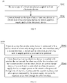
- an interface control method of an electronic device includes the following.
- a type of at least one device coupled with the electronic device is detected.
- a switch unit of the electronic device is controlled to switch a power-supply path of the electronic device.
- the electronic device is coupled with the at least one device through all or part of at least two interfaces.
- an interface control system of an electronic device includes a device type detection module and a power-supply path selection module.
- the device type detection module is configured to detect a type of at least one device coupled with the electronic device.
- the power-supply path selection module is configured to control, based on the type of the at least one device, a switch unit of the electronic device to switch a power-supply path of the electronic device.
- the electronic device is coupled with the at least one device through all or part of at least two interfaces.
- a computer-readable medium configured to store computer software instructions.
- the computer software instructions which are operable to execute the method in the first aspect, include programs designed to execute the above aspects.
- a device such as a wireless communication terminal and a positioning system
- these devices can have other names.
- functions of respective devices are similar to those of the disclosure, these devices shall all fall within the scope of claims of the disclosure and its equivalent technology.
- an electronic device to which the technical solutions of the implementations of the disclosure can be applied may be an augmented reality (AR) device, for example, AR glasses, an AR helmet, etc.
- AR augmented reality
- a method and a device are required, which can solve, at least to a certain extent, the problem in the related art that the electronic device can only be powered by the host device when the electronic device is coupled with the host device.
- FIG. 1 is a block diagram illustrating an electronic device according to implementations of the disclosure.
- the electronic device may be used through a connection with a host device (e.g., a smart terminal device, a dedicated server, etc.).
- the electronic device may be, for example, an AR device, such as AR glasses, an AR helmet, and the like.
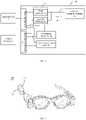
- an electronic device 10 includes a first interface 11, a second interface 12, a switch unit 13, and a control module 14.
- the first interface 11 and the second interface 12 may be, for example, a USB 2.0 interface, a Micro USB interface, a USB Type-C interface, or the like.
- a charging interface 11 may also be a lightning interface, or any other type of parallel port or serial port that is capable of power supply/charging.
- the switch unit 13 is coupled with the first interface 11 and the second interface 12 respectively, and configured to switch a power-supply path 15 of the electronic device 10.
- the power-supply path 15 is provided by the first interface 11 or the second interface 12. Power outputted by a device coupled with the first interface 11 or the second interface 11 is supplied to a circuit to-be-powered 16 of the electronic device 10 (e.g., an application processor (AP), a display module, an image collection module, a sensor, etc.) through the power-supply path 15.
- a device coupled with the first interface 11 or the second interface 11 is supplied to a circuit to-be-powered 16 of the electronic device 10 (e.g., an application processor (AP), a display module, an image collection module, a sensor, etc.) through the power-supply path 15.
- AP application processor
- the control module 14 is coupled with the first interface 11, the second interface 12, and the switch unit 13 respectively, and configured to detect a type of a device coupled with the electronic device 10 through the first interface 11 and/or the second interface 12.
- the control module 14 is configured to control, based on the type of the device, the switch unit 13 to switch the power-supply path 15 of the electronic device 10.
- the control module 14 may be, for example, a control chip or a microcontroller unit (MCU) that can fully or partially implement functions specified in a power delivery (PD) protocol.
- the control module 14 can recognize, based on the PD protocol, a type of a device coupled through the first interface and/or the second interface.
- the control module 14 can also negotiate, based on the PD protocol, a power-supply voltage, a current, a power-supply direction, and so on with the coupled device.
- the control module 14 is further configured to control the switch unit 13 based on the recognized type, to control the power-supply path 15 of the electronic device 10.
- the control module 14 can control the switch unit 13 to switch a power-supply circuit of the electronic device by detecting a type of a device coupled with the electronic device through these interfaces, to solve the technical problem in the related art that the electronic device can only be powered by a host device.
- the power-supply path of the electronic device of implementations of the disclosure varies with a type of a coupled device, which can solve the technical problem in the related art that the electronic device can only be powered by the host device, thereby prolonging a battery life of the electronic device when in use.
- FIG. 2 is a block diagram illustrating another electronic device according to implementations of the disclosure.
- a switch unit 23 of an electronic device 20 includes a first switch 231 and a second switch 232.
- the first interface 11 is coupled with a device to-be-powered 16 of the electronic device 20 through the first switch 231.
- the second interface 12 is coupled with the device to-be-powered 16 through the second switch 232.
- a capacitor C coupled with the first switch 231 and the second switch 232 is configured to maintain power supply when the power-supply path 15 is switched, which can prevent power failure of the electronic device 20.
- first switch 231 and the second switch 232 may be, for example, controllable switches, such as controllable transistors, which is not limited in the disclosure.
- a control module 24 is configured to control the first switch 231 and/or the second switch 232 to be turned on based on a detected type of a device coupled with the electronic device 20, to switch the power-supply path 15 of the electronic device 20.
- FIG. 3A and FIG. 3B are schematic diagrams exemplarily illustrating controlled states of the first switch and the second switch when the electronic device is coupled with different devices, respectively.
- the control module 24 upon detecting that the electronic device 20 is coupled with a device 1 which is a host only through the first interface 11, the control module 24 is configured to control the first switch 231 to be turned on and control the second switch 232 to be turned off, to allow the device 1 which is a host to supply power to the circuit to-be-powered 16.
- the control module 24 is further configured to control the second switch 12 to be turned on, to allow the power-supply device 2 to supply power to the circuit to-be-powered 16. As such, it is no longer necessary to power the electronic device through the device 1, thereby saving power of the host device 1.
- control module 24 may also be configured to keep a state of the first switch 231 to be turned on, to allow power outputted by the power-supply device 2 to be supplied to the host device 1 through the first interface 11. That is, the host device 1 can be charged while the electronic device 20 is powered. As such, a battery life of the host device 1 can be further prolonged.
- FIG. 3A and FIG.3B only illustrate an example in which the first interface 11 is coupled with the device 1 which is a host and the second interface 12 is coupled with the power-supply device 2.
- the second interface 12 is coupled with the device 1 which is a host, and accordingly, the control module 24 is configured to control the second switch 232 to be turned on and control the first switch 231 to be turned off, to allow the device which is a host to supply power to the circuit to-be-powered 16 through the second interface 12.
- the first interface 11 is coupled with the power-supply device 2, and the first switch 231 is controlled to be turned on, to allow the power-supply device 2 to supply power to the circuit to-be-powered 16 through the first interface 11.
- the second switch 232 is controlled to keep turned on, to allow power outputted by the power-supply device 2 to be supplied to the host device 1 through the second interface 11, to charge the host device 1 at the same time.
- FIG. 4 is a block diagram illustrating yet another electronic device according to implementations of the disclosure.
- an electronic device 40 illustrated in FIG. 4 further includes a data selection unit 47.
- the data selection unit 47 is coupled with the first interface 11 and the second interface 12 respectively, and configured to select to transmit data through the first interface 11 or the second interface 12 under control of a control module 44.
- data inputted at the first interface 11 or the second interface 12 is outputted to a module ( e.g ., an AP) of the electronic device 40, or data of the electronic device 40 is outputted to other devices (e.g ., the host device 1) coupled with the electronic device 40 through the first interface 11 or the second interface 12.
- the electronic device 40 is AR glasses
- the first interface 11 and the second interface 12 are USB Type-C interfaces
- the data selection unit 47 selects, under control of the control module 44, an interface for data transmission with a coupled device is described.
- FIG. 5 is a schematic diagram exemplarily illustrating AR glasses according to implementations of the disclosure.
- a first USB Type-C interface 11 and a second USB Type-C interface 12 are arranged on one temple of the AR glasses 40.
- positions of the first interface 11 and the second interface 12 illustrated in FIG. 5 are merely exemplary and not intended to restrict the disclosure.
- the first interface 11 and the second interface 12 may also be arranged on two temples respectively.
- FIG. 6 is a schematic diagram exemplarily illustrating a USB Type-C socket interface.
- the USB Type-C interface supports forward insertion and reverse insertion.
- ports in a USB Type-C interface structure are divided into two parts by a dotted line in FIG. 6 . Arrangements of ports in the two parts are opposite to support forward and reverse insertion of a USB plug.
- ports TX1+, TX1-, RX1+, and RX1- provide two pairs of TX/RX differential lines, to support high-speed data transmission and reception that meets a USB 3.x protocol (e.g ., USB 3.0, USB 3.1, etc.).
- ports TX2+, TX2-, RX2+, and RX2- provide two pairs of TX/RX differential lines, to support high-speed data transmission and reception that meets a USB 3 protocol (e.g., USB 3.0, USB 3.1, etc.).
- TX/RX differential lines are used as data lines.
- TX1/RX1 are connected in forward insertion
- TX2/RX2 are connected in reverse insertion. Therefore, in any case, two pairs of differential lines will not be used.
- a display port (DP) alternate mode is to load a DP signal onto two pairs of "remaining" differential lines, thus, USB 3 and DP can work simultaneously.
- USB TPYE-C interfaces of the host device 1 and the AR glasses 40 are required to support a USB 3 high-speed data transmission mode and the DP alternate mode. That is, DP signal transmission and USB 3 high-speed data transmission (including transmitting Tx and receiving Rx) at the USB Type-C interface are performed simultaneously.
- the AR glasses 40 are configured to drive an image collection module (e.g., a camera) and other sensors of the AR glasses 40, and transmit data collected by the image collection module and the sensors to the host device 1 through two pairs of TX1/RX1 differential lines (take forward insertion as an example).
- the host device 1 is configured to perform operations such as image rendering on received data, and transmit a rendered picture to the AR glasses 40 through another two pairs of TX2/RX2 differential lines for display.
- the USB 3 high-speed data transmission mode and the DP alternate mode can be supported at the same time.
- the USB Type-C interface also supports four VBUSs and four GNDs to transmit power.
- CC1 and CC2 ports are used for PD protocol communication.
- a master device and a slave device communicate with each other through CC1.
- the master device and the slave device communicate with each other through CC2.
- SBU1/SBU2 ports can be used to transmit side band (SB) data information of a device such as display port configuration data (DPCD), extended display identification data (EDID).
- SB side band
- DPCD display port configuration data
- EDID extended display identification data
- Two pairs of D+/D- data lines are configured for data transmission compatible with a USB 2 version.
- FIG. 7 is a schematic diagram illustrating a data selection unit according to implementations of the disclosure.
- a data selection unit 47 includes a first data selection unit 471, a second data selection unit 472, a third data selection unit 473, and a fourth data selection unit 474.
- FIG. 8 is a schematic diagram exemplarily illustrating another data selection unit according to implementations of the disclosure.
- the first data selection unit 471 may be, for example, coupled with D+/D- ports of the USB Type-C interface in FIG. 6 , and configured to select to transmit data through D+/D- data lines of the first interface 11 or the second interface 12 under control of the control module 44.
- the first data selection unit 471 may be, for example, a controllable switch.
- the first data selection unit 471 is configured to select to transmit data with a coupled device through the first interface 11 or the second interface 12, such as data TYPEC1-DP/DM of the first interface 11, or data TYPEC2-DP/DM of the second interface 12.
- Data DP/DM selected is inputted to an audio switch (AS).
- a host device 1 e.g., a smart phone
- may only have a USB Type-C interface for coupling with an audio output device e.g., an earphone, a speaker, etc.
- an audio output device e.g., an earphone, a speaker, etc.
- no conventional audio output device interface e.g., a 3.5 mm audio interface
- the control module 44 is configured to control the first data selection unit 471 to select to output audio data to the audio output device 3 through the second interface 12.
- the electronic device 40 is AR glasses
- the host device 1 is configured to transmit an image of a rendered picture and audio data of the rendered picture to the AR glasses 40 via the first interface 11 in the DP alternate mode through high-speed data transmission lines (TX/RX).
- the AR glasses 40 are configured to parse received data, extract audio data from the received data, and output audio data to the audio output device 3 through D+/D- data lines of the second interface 12.
- an audio output device such as an earphone can still be used when the host device 1 without an independent earphone interface is coupled with the electronic device 40.
- FIG. 7 illustrates an example in which the electronic device is coupled with the host device 1 through the first interface 11 and coupled with the audio output device 3 through the second interface 12.
- the electronic device may also be coupled with the host device 1 through the second interface 12 and coupled with the audio output device 3 through the first interface 11.
- the control module 44 is configured to control the first data selection unit 471 to output audio data to the audio output device 3 through the first interface 11.
- the second data selection unit 472 may be, for example, coupled with TX1/TX2 ports of the USB Type-C interface in FIG. 6 , and configured to select to transmit transmission data (TX) through data lines TX1/TX2 of the first interface 11 or the second interface 12 under control of the control module 44.
- TX transmission data
- the second data selection unit 472 includes a first port Port21, a second port Port22, and a third port Port23.
- the second data selection unit 472 is a controllable data selector (e.g., a MUX).
- the data selector is generally configured to select any one of paths according to needs in multiplexed data transmission. As illustrated in FIG. 8 ,
- the second data selection unit 472 is configured to select to connect the first port Port21 with the third port Port23 or select to connect the second port Port22 with the third port Port23, to select to output TypeC1-TX1 and TypeC1-TX2 inputted at the first interface 11 or TypeC2- TX1 and TypeC2-TX2 inputted at the second interface 12 through the third port Port 23, for example, output to a DP/USB3 demultiplexer (DeMUX).
- DeMUX DP/USB3 demultiplexer
- the third data selection unit 473 may be, for example, coupled with RX1/RX2 ports of the USB Type-C interface in FIG. 6 , and configured to select to transmit reception data (RX) through data lines RX1/RX2 of the first interface 11 or the second interface 12 under control of the control module 44.
- the third data selection unit 473 includes a first port Port31, a second port Port32, and a third port Port33.
- the third data selection unit 473 is a controllable data selector (e.g ., a MUX). As illustrated in FIG.
- the third data selection unit 473 is configured to select to connect the first port Port31 with the third port Port33 or select to connect the second port Port32 with the third port Port33, to select to output data (RX1/RX2) outputted by a DP/USB3 DeMUX through the first interface 11 or the second interface 12 to an external device coupled with the third data selection unit 473, for example, output data (e.g ., TypeC1-RX1 and TypeCl-RX2) through the first interface 11 or data ( e.g ., TypeC2-RX1 and TypeC2-RX2) through the second interface 12 to the external device.
- output data e.g ., TypeC1-RX1 and TypeCl-RX2
- data e.g ., TypeC2-RX1 and TypeC2-RX2
- the electronic device 40 is AR glasses, referring to FIG. 4 and FIG. 8 , the electronic device 40 for example is coupled with a host device 1 through the first interface 11 and coupled with other devices 3 (e.g., the above-mentioned audio output device or the above-mentioned power-supply device) through the second interface 12.
- the control module 44 is configured to control the second data selection unit 472 to communicate the first port Port_21 with the third port Port_23, and control the third data selection unit 473 to communicate the first port Port_21 with the third port Port_33, to transmit high-speed USB transmission data and high-speed USB reception data with the host device 1 through the first interface 11.
- the fourth data selection unit 474 may be, for example, coupled with SBU1/SBU2 ports of the USB Type-C interface in FIG. 6 , and configured to select to transmit side band data through data lines SBU1/SBU2 of the first interface 11 or the second interface 12 under control of the control module 44.
- the fourth data selection unit 474 may be, for example, a controllable switch.
- the fourth data selection unit 474 is configured to select to transmit side band data at a USB Type-C interface with a coupled device through the first interface 11 or the second interface 12.
- FIG. 9 is a schematic diagram illustrating an interface control method of an electronic device according to implementations of the disclosure. For details not disclosed in method implementations of the disclosure, reference may be made to the relevant implementations of the electronic device of the disclosure. As illustrated in FIG. 9 , the method includes all or part of the following.
- At S502 a type of at least one device coupled with the electronic device is detected.
- the electronic device is coupled with the at least one device through all or part of at least two interfaces.
- a switch unit of the electronic device is controlled based on the type of the at least one device to switch a power-supply path of the electronic device.
- the at least two interfaces may include, for example, the first interface 11 and the second interface 12.
- the power-supply path of the electronic device with multiple interfaces varies with a type of a coupled device when the electronic device is in use, which can solve the technical problem in the related art that the electronic device can only be powered by a host device.
- FIG. 10 is a schematic diagram illustrating an interface control method of an electronic device according to implementations of the disclosure. Different from the method illustrated in FIG. 9 , the method illustrated in FIG. 10 further provides a specific implementation of controlling, based on the type of the device, the switch unit of the electronic device to switch the power-supply path of the electronic device. That is, the method further provides a specific implementation of the operations at S504.
- the operations at S504 include the following.
- the switch unit upon detecting that the electronic device is coupled with the device which is a host only through one of the first interface and the second interface, the switch unit is controlled, to allow the host to supply power to a circuit to-be-powered.
- the switch unit is controlled, to allow the power-supply device to supply power to the circuit to-be-powered through one of the first interface and the second interface, and allow power outputted by the power-supply device to be supplied to the host through the other interface.
- the host device coupled with the electronic device can be charged while the electronic device is powered, thereby further prolonging the battery life of the host device 1.
- FIG. 11 is a schematic diagram illustrating an interface control method of an electronic device according to implementations of the disclosure. As illustrated in FIG. 9 , the method includes all or part of the following.
- a type of a device coupled with the electronic device through a first interface and/or a second interface of the electronic device is detected.
- a switch unit of the electronic device is controlled based on the type of the device to switch a power-supply path of the electronic device.
- a data selection unit of the electronic device is controlled based on the type of the device to select to transmit data through the first interface or the second interface.
- the difference from the method 50 illustrated in FIG. 9 is that the method 60 illustrated in FIG. 11 further includes the operations at S602.
- the first interface and the second interface may be, for example, USB Type-C interfaces.
- FIG. 12 is a schematic diagram illustrating an interface control method of an electronic device according to implementations of the disclosure. As illustrated in FIG. 12 , the method includes all or part of the following.
- the data selection unit is controlled to select to output audio data to the audio output device through the first interface or the second interface.
- the data selection unit is controlled to select to transmit at least one of transmission data, reception data, or side band data with the host through the first interface or the second interface which is coupled with the host.
- the difference from the method illustrated in FIG. 11 is that the method illustrated in FIG. 12 further provides a specific implementation of controlling, based on the type of the device, the data selection unit of the electronic device to select to transmit data through the first interface or the second interface. That is, a specific implementation of the operations at S602 is further provided.
- the power-supply path of the electronic device varies with a type of a coupled device, which can solve the technical problem in the related art that the electronic device can only be powered by a host device, thereby significantly prolonging the battery life of electronic device.
- the power-supply device that supplies power to the electronic device can also charge the host device through a connection interface between the electronic device and the host device, which can solve the problem that the host device cannot be charged when the electronic device is coupled with the host device, without adding a charging interface for the host device.
- the electronic device when the electronic device is coupled with the host device, the electronic device can also be coupled with an audio output device such as an earphone through another interface of the electronic device, which can solve the problem that the audio output device cannot be used when the electronic device is coupled with the host device, without adding an independent earphone interface for the host device.
- an audio output device such as an earphone
- system and “network” herein are generally used interchangeably.
- the term “and/or” herein is merely used to describe the association of associated objects and indicates that there can be three relationships. For example, “ A and/or B " may mean three situations, that is, A exists alone, A and B exist at the same time, and B exists alone.
- the character “/” herein generally indicates that the associated objects before and after the character are in an "or” relationship.
- sequence numbers of the above-mentioned processes does not mean an execution sequence.
- the execution sequence of the processes should be determined according to functions and an internal logic of the processes, which should not constitute any limitation on an implementation process of the implementations of the disclosure.
- FIG. 13 is a schematic block diagram illustrating an interface control system 130 of an electronic device according to implementations of the disclosure.
- the system 130 includes a device type detection module 1301 and a power-supply path selection module 1302.
- the device type detection module 1301 is configured to detect a type of at least one device coupled with the electronic device.
- the power-supply path selection module 1302 is configured to control, based on the type of the at least one device, a switch unit of the electronic device to switch a power-supply path of the electronic device.
- the electronic device is coupled with the at least one device through all or part of at least two interfaces.
- the at least two interfaces include a first interface and a second interface.
- the power-supply path selection module 1302 is configured to control the switch unit to allow a host to supply power to a circuit to-be-powered, upon detecting that the electronic device is coupled with the device which is a host only through one of the first interface and the second interface.
- the power-supply path selection module 1302 is configured to control the switch unit to allow a power-supply device to supply power to the circuit to-be-powered through the other one of the first interface and the second interface which is not coupled with the device which is a host, and allow the power outputted by the power-supply device to be supplied to the host through one of the first interface and the second interface, upon detecting that the electronic device is coupled with another device through the other interface and the other device is a power-supply device.
- the system 130 further includes an interface selection module.
- the interface selection module is configured to control, based on the type of the device, a data selection unit of the electronic device to select to transmit data through the first interface or the second interface.
- the first interface and the second interface are each a USB Type-C interface.
- the interface selection module is configured to control a first data selection unit to select to output audio data to an audio output device through the other one of the first interface and the second interface, upon detecting that the electronic device is coupled with the device which is a host through one of the first interface and the second interface and coupled with another device which is an audio output device through the other one of the first interface and the second interface.
- the interface selection module is configured to control the data selection unit to select to transmit at least one of transmission data, reception data, or side band data with the host through the first interface or the second interface which is coupled with the host.
- modules, units, and other operations and/or functions in the system 130 of implementations of the disclosure are to respectively implement corresponding processes of the method described with reference to FIG. 9 to FIG. 12 , which is not repeated herein for the sake of brevity.
- FIG. 14 illustrates an electronic device 800 for implementing implementations of the disclosure according to implementations of the disclosure.
- the electronic device 800 illustrated in FIG. 14 is merely an example, and should not impose any limitations on the functions and the use scope of implementations of the disclosure.
- the electronic device may be an AR device such as AR glasses, an AR helmet, and the like.
- the electronic device 800 may be in a form of a general-purpose computing device.
- Components of the electronic device 800 may include, but are not limited to, at least one processing unit 810, at least one storage unit 820, and a bus 830 coupled with different system components (including the storage unit 820 and the processing unit 810).
- the storage unit stores program codes.
- the program codes when executed by the processing unit 810, are operable with the processing unit 810 to perform all or part of the operations of various exemplary implementations of the disclosure described in the above-mentioned "exemplary method" of the specification.
- the storage unit 820 may include a readable medium in a form of a transitory storage unit, such as a random access memory (RAM) 8201 and/or a cache 8202.
- the storage unit 820 may further include a read-only memory (ROM) 8203.
- the storage unit 820 may further include a program/utility 8204 having a set (at least one) of program modules 8205 including, but not limited to, an operating system, one or more application programs, other program modules, and program data.
- program modules 8205 including, but not limited to, an operating system, one or more application programs, other program modules, and program data.
- the implementation of a network environment may be included in each or some combination of these examples.
- the bus 830 may be representative of one or more of several types of bus structures, including a memory bus or a memory controller, a peripheral bus, a graphics acceleration port, a processing unit, or a local bus using any of a variety of bus structures.
- the electronic device 800 may also communicate with one or more external devices 700 (e.g., a keyboard, a pointing device, a bluetooth device, etc.).
- the electronic device 800 may also communicate with one or more devices that allow a user to interact with the electronic device 800, and/or with any device (e.g., a router, a modem, etc.) that allow the electronic device 800 to communicate with one or more other computing devices. Such communication may be performed through an input/output (I/O) interface 850.
- the electronic device 800 may communicate with one or more networks (e.g ., a local area network (LAN), a wide area network (WAN), and/or a public network such as the Internet) through a network adapter 860. As illustrated in FIG.
- the network adapter 860 can communicate with other modules of the electronic device 800 via the bus 830. It should be understood that, although not illustrated, other hardware and/or software modules may be used in conjunction with the electronic device 800, and include but not limited to: a microcode, a device driver, a redundant processing unit, an external disk drive array, an RAID system, a tape drive, and a data backup storage system.
- exemplary implementations described herein may be implemented by software or software combined with necessary hardware. Therefore, the technical solutions of the implementations of the disclosure may be embodied in a form of a software product.
- the software product may be stored in a non-transitory storage medium (which may be a CD-ROM, a USB, a mobile hard disk, etc.) or stored on a network, and include several instructions to cause a computing device (which may be a personal computer, a server, a terminal device, or a network device, etc.) to execute the method according to the implementations of the disclosure.
- a computer-readable storage medium stores a program product capable of implementing the above method in the specification.
- various aspects of the disclosure may also be implemented in a form of a program product.
- the program product includes program codes. When the program product is run on a terminal device, the program codes cause the terminal device to perform the operations of various exemplary implementations of the disclosure described in the above-mentioned "exemplary method" of the specification.
- FIG. 15 illustrates a program product 900 for implementing the above method of implementations of the disclosure according to implementations of the disclosure.
- the program product may adopt a portable compact disk read-only memory (CD-ROM) and include program codes, and may run on a terminal device, such as a personal computer.
- CD-ROM compact disk read-only memory
- the program product of the disclosure is not limited thereto, and in this document, a readable storage medium may be any tangible medium that contains or stores programs, the programs can be used by or in conjunction with an instruction execution system, an apparatus, or a device.
- the program product may be any combination of one or more readable media.
- the readable medium may be a readable signal medium or a readable storage medium.
- the readable storage medium may be, but not limited to, an electrical, magnetic, optical, electromagnetic, infrared, or semiconductor system, apparatus, or device, or a combination of any of the above.
- Specific examples (non-exhaustive list) of the readable storage medium include: an electrical connection with one or more wires, a portable disk, a hard disk, a RAM, a ROM, an erasable programmable read only memory (EPROM or flash memory), an optical fiber, a CD-ROM, an optical storage device, a magnetic storage device, or any suitable combination of the above.
- a computer-readable signal medium may include a propagated data signal in baseband or as part of a carrier wave, which carries readable program codes. Such propagated data signal may take a variety of forms, including but not limited to, an electromagnetic signal, an optical signal, or any suitable combination of the foregoing.
- the readable signal medium may also be any readable medium other than the readable storage medium, and the storage medium can send, propagate, or transmit programs which can be used by or in connection with an instruction execution system, an apparatus, or a device.
- Program codes embodied in a readable medium may be transmitted using any suitable medium, including but not limited to wireless, wireline, optical fiber cable, RF, etc., or any suitable combination of the foregoing.
- the program codes used to perform the operations of the disclosure may be written in any combination of one or more programming languages.
- the programming languages may include object-oriented programming languages (e.g ., Java, C++, etc.) and conventional procedural programming languages (e.g ., C language or similar programming languages).
- the program codes may be executed entirely on a user's computing device, executed partly on the user's computing device, executed as an independent software package, executed partly on the user's computing device and partly on a remote computing device, or entirely on the remote computing device or on a server.
- the remote computing device may be coupled with a user computing device through any kind of network (including a local area network (LAN) or a wide area network (WAN), etc.), or may be coupled with an external computing device (for example, by means of an Internet service provider for Internet connection).
- LAN local area network
- WAN wide area network
- modules or units of the device for action execution are mentioned in the above detailed description, the division is not mandatory.
- features and functions of two or more modules or units described above may be embodied in a module or unit.
- features and functions of a module or unit described above may be further divided to be embodied in multiple modules or units.
- exemplary implementations described herein may be implemented by software or software combined with necessary hardware. Therefore, the technical solutions of the implementations of the disclosure may be embodied in a form of a software product.
- the software product may be stored in a non-transitory storage medium (which may be a CD-ROM, a USB, a mobile hard disk, etc.) or stored on the network, and include several instructions to cause a computing device (which may be a personal computer, a server, a mobile terminal, or a network device, etc.) to execute the method according to the implementations of the disclosure.
- the system, the device, and the method disclosed in implementations of the disclosure may be implemented in other manners.
- the device/apparatus implementations described above are merely illustrative; for instance, the division of the unit is only a logical function division and there can be other manners of division during actual implementations, for example, multiple units or assemblies may be combined or may be integrated into another system, or some features may be ignored, omitted, or not performed.
- coupling or communication connection between each illustrated or discussed component may be direct coupling or communication connection, or may be indirect coupling or communication among devices or units via some interfaces, and may be electrical connection, mechanical connection, or other forms of connection.
- the units described as separate components may or may not be physically separated, the components illustrated as units may or may not be physical units, that is, they may be in a same place or may be distributed to multiple network elements. All or part of the units may be selected according to actual needs to achieve the purpose of the technical solutions of the implementations.
- the functional units in various implementations of the disclosure may be integrated into one processing unit, or each unit may be physically present, or two or more units may be integrated into one unit.
- the functional unit may be stored in a computer-readable storage medium when it is implemented in the form of a software functional unit and is sold or used as a separate product.
- the computer software product is stored in a storage medium and includes instructions for causing a computer device (which may be a personal computer, a server, or a network device, or the like) to perform all or part of the operations described in various implementations of the disclosure.
- the storage medium may include various medium capable of storing program codes, such as a universal serial bus (USB), a removable hard disk, a ROM, a RAM, Disk, compact disc (CD), or the like.
Applications Claiming Priority (2)
| Application Number | Priority Date | Filing Date | Title |
|---|---|---|---|
| CN201911106776.0A CN110879792B (zh) | 2019-11-13 | 2019-11-13 | 电子设备及其接口控制方法 |
| PCT/CN2020/125976 WO2021093627A1 (fr) | 2019-11-13 | 2020-11-02 | Dispositif électronique, et procédé et système de commande d'interface de dispositif électronique |
Publications (2)
| Publication Number | Publication Date |
|---|---|
| EP4053707A1 true EP4053707A1 (fr) | 2022-09-07 |
| EP4053707A4 EP4053707A4 (fr) | 2023-01-11 |
Family
ID=69729281
Family Applications (1)
| Application Number | Title | Priority Date | Filing Date |
|---|---|---|---|
| EP20887274.7A Pending EP4053707A4 (fr) | 2019-11-13 | 2020-11-02 | Dispositif électronique, et procédé et système de commande d'interface de dispositif électronique |
Country Status (4)
| Country | Link |
|---|---|
| US (1) | US20220269326A1 (fr) |
| EP (1) | EP4053707A4 (fr) |
| CN (1) | CN110879792B (fr) |
| WO (1) | WO2021093627A1 (fr) |
Families Citing this family (3)
| Publication number | Priority date | Publication date | Assignee | Title |
|---|---|---|---|---|
| CN110879792B (zh) * | 2019-11-13 | 2024-01-23 | Oppo广东移动通信有限公司 | 电子设备及其接口控制方法 |
| TW202145023A (zh) * | 2020-05-19 | 2021-12-01 | 智原科技股份有限公司 | 轉接裝置 |
| CN112181873A (zh) * | 2020-09-25 | 2021-01-05 | 紫光恒越技术有限公司 | 一种控制芯片上接口工作状态的方法以及装置 |
Family Cites Families (22)
| Publication number | Priority date | Publication date | Assignee | Title |
|---|---|---|---|---|
| TWI467886B (zh) * | 2012-08-20 | 2015-01-01 | Quanta Comp Inc | 電子裝置以及電子系統 |
| CN202872406U (zh) * | 2012-09-19 | 2013-04-10 | 青岛海信移动通信技术股份有限公司 | 一种接口复用电路及移动终端 |
| KR102335910B1 (ko) * | 2015-03-01 | 2021-12-06 | 삼성전자주식회사 | 전원 제어 방법 및 장치 |
| KR102295686B1 (ko) * | 2015-04-15 | 2021-08-31 | 삼성전자주식회사 | 외부 전자 장치와 하이브리드 통신을 수행하는 전자 장치 및 방법 |
| KR102476581B1 (ko) * | 2015-10-02 | 2022-12-12 | 삼성전자 주식회사 | 적응적 전력 관리 방법 및 장치 |
| CN105549708B (zh) * | 2015-12-07 | 2019-02-05 | 联想(北京)有限公司 | 一种供电方法及第一电子设备 |
| KR102391487B1 (ko) * | 2015-12-15 | 2022-04-28 | 삼성전자주식회사 | 충전 및 데이터 통신 경로 제어 방법 및 이를 구현한 전자 장치 |
| CN105677611B (zh) * | 2015-12-31 | 2020-02-07 | 北京小鸟看看科技有限公司 | 一种便携式设备以及控制hdmi信号输出的方法 |
| KR102511514B1 (ko) * | 2016-02-03 | 2023-03-20 | 삼성전자주식회사 | 다양한 충전 방식을 이용한 고속 충전 방법 및 장치 |
| US20170277650A1 (en) * | 2016-03-25 | 2017-09-28 | Le Holdings (Beijing) Co., Ltd. | User equipment and method for data transmission |
| US10644516B2 (en) * | 2016-05-19 | 2020-05-05 | Microsoft Technology Licensing, Llc | Charging multiple user apparatuses |
| CN106095007A (zh) * | 2016-07-29 | 2016-11-09 | 北京小鸟看看科技有限公司 | 一种头戴显示设备 |
| KR20180058089A (ko) * | 2016-11-23 | 2018-05-31 | 삼성전자주식회사 | 외부 전자 장치와 통신하는 전자 장치 및 방법 |
| CN108270253A (zh) * | 2016-12-30 | 2018-07-10 | 维沃移动通信有限公司 | 一种充电方法及移动终端 |
| CN107291415B (zh) * | 2017-05-31 | 2020-03-03 | 维沃移动通信有限公司 | 一种充电及音频数据处理的方法及终端 |
| KR102486833B1 (ko) * | 2017-08-23 | 2023-01-11 | 삼성전자주식회사 | 전자 장치들간의 전원 제어 방법 및 전자 장치 |
| TWI646433B (zh) * | 2017-09-12 | 2019-01-01 | 宏碁股份有限公司 | 頭戴式顯示系統 |
| KR102635443B1 (ko) * | 2018-02-27 | 2024-02-13 | 삼성전자주식회사 | 전력을 공급하고 있는 외부 전자 장치의 연결 해제에 기반하여, 전자 장치와 연결된 다른 외부 장치로부터 전력을 수신하는 방법 및 이를 구현한 전자 장치 |
| US11101649B2 (en) * | 2018-12-12 | 2021-08-24 | Intel Corporation | Interface circuitry with multiple direct current power contacts |
| CN110309094A (zh) * | 2019-06-28 | 2019-10-08 | 联想(北京)有限公司 | 电子设备及其控制方法 |
| KR102651715B1 (ko) * | 2019-07-30 | 2024-03-28 | 삼성전자주식회사 | Usb 장치의 손상을 방지하기 위한 전자 장치 및 그의 동작 방법 |
| CN110879792B (zh) * | 2019-11-13 | 2024-01-23 | Oppo广东移动通信有限公司 | 电子设备及其接口控制方法 |
-
2019
- 2019-11-13 CN CN201911106776.0A patent/CN110879792B/zh active Active
-
2020
- 2020-11-02 EP EP20887274.7A patent/EP4053707A4/fr active Pending
- 2020-11-02 WO PCT/CN2020/125976 patent/WO2021093627A1/fr unknown
-
2022
- 2022-05-12 US US17/743,159 patent/US20220269326A1/en active Pending
Also Published As
| Publication number | Publication date |
|---|---|
| US20220269326A1 (en) | 2022-08-25 |
| WO2021093627A1 (fr) | 2021-05-20 |
| CN110879792A (zh) | 2020-03-13 |
| CN110879792B (zh) | 2024-01-23 |
| EP4053707A4 (fr) | 2023-01-11 |
Similar Documents
| Publication | Publication Date | Title |
|---|---|---|
| EP4053707A1 (fr) | Dispositif électronique, et procédé et système de commande d'interface de dispositif électronique | |
| CN109286764B (zh) | 具有usb type-c接口的电视机 | |
| US8195852B2 (en) | Configurable connector for system-level communication | |
| CN108666826B (zh) | 一种转接头、终端设备和转接头系统 | |
| US8346985B2 (en) | Receiver configured to pair to multiple wireless devices | |
| CN107315556B (zh) | 显示装置 | |
| EP2711843B1 (fr) | DisplayPort sur Interface mécanique USB | |
| EP2466480B1 (fr) | Clé électronique et procédé de fonctionnement d'un dispositif d'entrée externe, et system d'entrée externe avec la clé électronique | |
| US7930463B2 (en) | Information processing apparatus | |
| US11403245B2 (en) | Terminal, terminal peripheral, signal transmission system and signal sending and receiving method | |
| US10198392B2 (en) | Peripheral device, host device, and processing method | |
| CN107506322B (zh) | 实现USB设备检测的Type-C适配器、通道控制方法 | |
| CN210129132U (zh) | 交互智能平板 | |
| CN213151196U (zh) | 一种信号转接器 | |
| CN115733549B (zh) | Pcie网卡及其接口模式的切换方法、电子设备及存储介质 | |
| CN210129206U (zh) | 交互智能平板 | |
| US20170220069A1 (en) | Docking apparatus and control method thereof | |
| EP3041174A1 (fr) | Système de couplage d'un dispositif électronique et procédé | |
| EP2645202B1 (fr) | Procédé d'alimentation d'un terminal de réseau sans fil et terminal de réseau sans fil | |
| CN117492525B (zh) | Usb扩展设备、带宽管理方法和可读存储介质 | |
| WO2022170861A1 (fr) | Procédé de transmission de données de dispositif électronique, dispositif électronique et circuit d'interface | |
| CN111949103B (zh) | 具数据存取、传输及电源管理的整合电子装置及其方法 | |
| CN117498105A (zh) | 一种电子设备和连接部件 | |
| CN114816995A (zh) | 一种基于Type C接口的整机调试电路和设备 | |
| CN116560736A (zh) | 一种显示系统、电子设备和通信控制方法 |
Legal Events
| Date | Code | Title | Description |
|---|---|---|---|
| STAA | Information on the status of an ep patent application or granted ep patent |
Free format text: STATUS: THE INTERNATIONAL PUBLICATION HAS BEEN MADE |
|
| PUAI | Public reference made under article 153(3) epc to a published international application that has entered the european phase |
Free format text: ORIGINAL CODE: 0009012 |
|
| STAA | Information on the status of an ep patent application or granted ep patent |
Free format text: STATUS: REQUEST FOR EXAMINATION WAS MADE |
|
| 17P | Request for examination filed |
Effective date: 20220531 |
|
| AK | Designated contracting states |
Kind code of ref document: A1 Designated state(s): AL AT BE BG CH CY CZ DE DK EE ES FI FR GB GR HR HU IE IS IT LI LT LU LV MC MK MT NL NO PL PT RO RS SE SI SK SM TR |
|
| A4 | Supplementary search report drawn up and despatched |
Effective date: 20221208 |
|
| RIC1 | Information provided on ipc code assigned before grant |
Ipc: G06F 3/01 20060101ALI20221202BHEP Ipc: G06F 1/26 20060101ALI20221202BHEP Ipc: G06F 1/16 20060101ALI20221202BHEP Ipc: G06F 13/40 20060101ALI20221202BHEP Ipc: G06F 13/10 20060101AFI20221202BHEP |
|
| DAV | Request for validation of the european patent (deleted) | ||
| DAX | Request for extension of the european patent (deleted) |