EP4053597A1 - Super-resolution radon transform based on thresholding - Google Patents
Super-resolution radon transform based on thresholding Download PDFInfo
- Publication number
- EP4053597A1 EP4053597A1 EP21207070.0A EP21207070A EP4053597A1 EP 4053597 A1 EP4053597 A1 EP 4053597A1 EP 21207070 A EP21207070 A EP 21207070A EP 4053597 A1 EP4053597 A1 EP 4053597A1
- Authority
- EP
- European Patent Office
- Prior art keywords
- computer
- seismic data
- radon transform
- data
- graph
- Prior art date
- Legal status (The legal status is an assumption and is not a legal conclusion. Google has not performed a legal analysis and makes no representation as to the accuracy of the status listed.)
- Withdrawn
Links
Images


Classifications
-
- G—PHYSICS
- G01—MEASURING; TESTING
- G01V—GEOPHYSICS; GRAVITATIONAL MEASUREMENTS; DETECTING MASSES OR OBJECTS; TAGS
- G01V1/00—Seismology; Seismic or acoustic prospecting or detecting
- G01V1/28—Processing seismic data, e.g. for interpretation or for event detection
- G01V1/36—Effecting static or dynamic corrections on records, e.g. correcting spread; Correlating seismic signals; Eliminating effects of unwanted energy
- G01V1/364—Seismic filtering
-
- G—PHYSICS
- G01—MEASURING; TESTING
- G01V—GEOPHYSICS; GRAVITATIONAL MEASUREMENTS; DETECTING MASSES OR OBJECTS; TAGS
- G01V1/00—Seismology; Seismic or acoustic prospecting or detecting
- G01V1/28—Processing seismic data, e.g. for interpretation or for event detection
-
- G—PHYSICS
- G06—COMPUTING OR CALCULATING; COUNTING
- G06T—IMAGE DATA PROCESSING OR GENERATION, IN GENERAL
- G06T5/00—Image enhancement or restoration
- G06T5/10—Image enhancement or restoration using non-spatial domain filtering
-
- G—PHYSICS
- G06—COMPUTING OR CALCULATING; COUNTING
- G06T—IMAGE DATA PROCESSING OR GENERATION, IN GENERAL
- G06T5/00—Image enhancement or restoration
- G06T5/70—Denoising; Smoothing
-
- G—PHYSICS
- G01—MEASURING; TESTING
- G01V—GEOPHYSICS; GRAVITATIONAL MEASUREMENTS; DETECTING MASSES OR OBJECTS; TAGS
- G01V1/00—Seismology; Seismic or acoustic prospecting or detecting
- G01V1/28—Processing seismic data, e.g. for interpretation or for event detection
- G01V1/32—Transforming one recording into another or one representation into another
-
- G—PHYSICS
- G01—MEASURING; TESTING
- G01V—GEOPHYSICS; GRAVITATIONAL MEASUREMENTS; DETECTING MASSES OR OBJECTS; TAGS
- G01V2210/00—Details of seismic processing or analysis
- G01V2210/20—Trace signal pre-filtering to select, remove or transform specific events or signal components, i.e. trace-in/trace-out
- G01V2210/23—Wavelet filtering
-
- G—PHYSICS
- G01—MEASURING; TESTING
- G01V—GEOPHYSICS; GRAVITATIONAL MEASUREMENTS; DETECTING MASSES OR OBJECTS; TAGS
- G01V2210/00—Details of seismic processing or analysis
- G01V2210/20—Trace signal pre-filtering to select, remove or transform specific events or signal components, i.e. trace-in/trace-out
- G01V2210/24—Multi-trace filtering
- G01V2210/244—Radon transform
-
- G—PHYSICS
- G01—MEASURING; TESTING
- G01V—GEOPHYSICS; GRAVITATIONAL MEASUREMENTS; DETECTING MASSES OR OBJECTS; TAGS
- G01V2210/00—Details of seismic processing or analysis
- G01V2210/40—Transforming data representation
- G01V2210/46—Radon transform
-
- G—PHYSICS
- G06—COMPUTING OR CALCULATING; COUNTING
- G06T—IMAGE DATA PROCESSING OR GENERATION, IN GENERAL
- G06T2207/00—Indexing scheme for image analysis or image enhancement
- G06T2207/20—Special algorithmic details
- G06T2207/20048—Transform domain processing
-
- G—PHYSICS
- G06—COMPUTING OR CALCULATING; COUNTING
- G06T—IMAGE DATA PROCESSING OR GENERATION, IN GENERAL
- G06T2207/00—Indexing scheme for image analysis or image enhancement
- G06T2207/20—Special algorithmic details
- G06T2207/20048—Transform domain processing
- G06T2207/20064—Wavelet transform [DWT]
-
- G—PHYSICS
- G06—COMPUTING OR CALCULATING; COUNTING
- G06T—IMAGE DATA PROCESSING OR GENERATION, IN GENERAL
- G06T2207/00—Indexing scheme for image analysis or image enhancement
- G06T2207/20—Special algorithmic details
- G06T2207/20172—Image enhancement details
- G06T2207/20182—Noise reduction or smoothing in the temporal domain; Spatio-temporal filtering
Definitions
- the present disclosure describes techniques for performing a super-resolution radon transform on seismic data.
- post-stack seismic data is received.
- Transformed seismic data is created from the received post-stack seismic data, including performing a super-resolution radon transform on the post-stack seismic data.
- Signal and noise regions are separated using the transformed seismic data, including using a defined muting function to remove unwanted noise.
- An inverse radon transform is performed using the separated signal and noise regions, outputting only signals.
- the described subject matter can be implemented using a computer-implemented method; a non-transitory, computer-readable medium storing computer-readable instructions to perform the computer-implemented method; and a computer-implemented system comprising one or more computer memory devices interoperably coupled with one or more computers and having tangible, non-transitory, machine-readable media storing instructions that, when executed by the one or more computers, perform the computer-implemented method/the computer-readable instructions stored on the non-transitory, computer-readable medium.
- the following detailed description describes systems, methods, and techniques for performing a super-resolution radon transform on seismic data, and is presented to enable any person skilled in the art to make and use the disclosed subject matter in the context of one or more particular implementations.
- the described techniques are capable of removing more multiple contamination on seismic data than existing algorithms.
- the techniques increase vertical resolution, minimize noise, and allow for the identification of small structures and subtle stratigraphic changes in target horizons. Such details are crucial for prospect generation during exploration and effective well placement and geo-steering in developmental projects as well as reservoir characterization, among other possible applications.
- the radon transform When the radon transform is applied to the field data, it can suffer from the typical problem of low resolution that arise as a consequence of insufficient dip or move-out difference between signal and noise. Increasing the resolution of the radon transform is very important, because its main use is to map mixed and overlapping events in the seismic gather to a new transform domain where they can be separated. Then, after muting undesired components, the data are projected back to the original domain retaining only the desired information. Many different methods can be developed for obtaining the radon transform in the time-offset, frequency-offset, or frequency-wavenumber domain with linear, parabolic, or hyperbolic basis function. The most commonly used method is inversion.
- the standard radon transform can usually be associated with the minimization of a cost function that penalizes the model m and the misfit between observed and predicted data in a least-square sense, for example, as given by: min ⁇ ⁇ m ⁇ 2 + 1 2 ⁇ d ⁇ Lm ⁇ 2 2 where d is the observed data, L is the inverse linear radon transform, and the parameter ⁇ > 0 balances the trade-off between the data approximation and the model.
- the standard radon transform implementation fulfills the requirement of a fast transform, but does not allow proper handling of problems associated with limited aperture and discretization.
- Equation (2) can be solved by an iteratively re-weighted least squares (IRLS) algorithm, due to its simplicity and efficiency.
- Sparse radon transform algorithms can be implemented in the frequency domain, which is now generally used in seismic processing. Even though the sparse radon transform algorithms can be recognized as being superior to standard radon transform algorithms, sparse radon transform algorithms can bring new problems, including large computation times, the introduction of artifacts, and the difficulty to set up the inversion parameters.
- Some implementations can use a sparse time-invariant radon transform in the time-frequency domain based on iterative radon model shrinkage, with good performance and reduced computational time. All these sparse radon transform algorithms demonstrate that the resolution can be increased to some level by the use of sparseness criteria. However, the performance still needs to be improved on real data, because the limitation comes from the realization from l0 norm to l1 norm.
- Some implementations can be based on a mathematical theory of super-resolution. Broadly speaking, the task can be cast as an inverse equation of recovering the original high-resolution image with fine details from coarse scale information, based upon reasonable assumptions or prior knowledge about the observation model.
- Equation (3) Two common themes that can be adopted to solve Equation (3) include: 1) greedy pursuit and 2) convex relaxation methods. So-called “greedy” strategies, such as strategies using matching pursuit type algorithms, can iteratively refine a sparse solution by successively identifying one or several components that yield an improvement in approximating the signal. These strategies can include relatively fast iterative procedures that are used extensively in practical applications, including sparse radon transform algorithms. The strategies take advantage of the sparsity structure by minimizing the t0 -norm, but they may converge to the local optima and require some prior information, like the cardinality s of the sparse solution. Therefore, the performance of the greedy strategies is not guaranteed in general, and only under strict conditions can they be shown to recover the sparest solution of the l0 norm regularization.
- Equation (3) Another approach for solving Equation (3) is to replace the nonconvex l0 function by its convex relaxation l1 norm, yielding the convex optimization Equation (2) for a high-resolution radon transform.
- Classical solutions to the l1 norm minimization problem have been well studied in the last few years.
- a great number of fast algorithms have been developed for solving large-scale l1 minimization problems. These methods do not require any prior information, but cannot fully recover the sparsest solution.
- this two-stage algorithm can be embedded in a continuation technique by assigning a decreasing sequence of the regularization parameter ⁇ .
- Applications of this implementation can suppress multiples in a series of synthetic and field seismic data sets.
- the synthetic examples clearly show that the algorithm can separate overlapping events with small dip differences which usually cannot be detected by conventional high-resolution schemes. Tests on field data can also indicate that the method outperforms commonly-used algorithms.
- a primary goal can be to obtain a sparsest solution of the l0 norm regularization Equation (3) by solving the l1 norm minimization Equation (2) with a combination of a greedy pursuit scheme.
- l 1 regularization Equation (2) One of the most popular methods for solving the l 1 regularization Equation (2) is the iterative shrinkage-thresholding algorithm (ISTA), where each iteration involves a forward and an inverse radon transform L T and L, followed by a shrinkage thresholding operator.
- IVA iterative shrinkage-thresholding algorithm
- the effect of this operator T ⁇ is to reduce the amplitude of each component of by ⁇ and vanish those negative results, thereby reducing the l 1 -norm.
- Equation (4) is an extension of the classical gradient method, which can be independently derived from different considerations. This shrinkage operator can also be used for high-resolution radon transform.
- this solution can be used as a warm start for the next stage and can provide an estimation about the sparsity level of the image in the transform domain.
- the number S i of local optimal magnitude can be identified on each row of the image m ⁇ .
- the total number s ⁇ i s i can be considered as the sparsity estimation of m ⁇ .
- the second stage can apply an iterative hard thresholding algorithm to solve the l0 norm regularization Equation (3).
- the iterative hard thresholding algorithm is the simplest one.
- the sparsest solution of the l0 norm regularization problem can be recovered, provided that there is a prior estimation of the sparsity level of the solution.
- Hs is the hard thresholding operator that sets all but the s largest (in magnitude) elements in the vector to zero. It can be established that, under some conditions, the iterative hard thresholding method Equation (9) can recover the s -sparse solution with near optimal accuracy.
- the previously-described iterative shrinkage and hard thresholding algorithms can be repeated until convergence criteria are satisfied.
- the combination of these two techniques can lead to the sparsest solution of the l0 -norm minimization problem.
- the traditional reweighted least-square (IRLS)-based sparse radon transform algorithms can require a matrix inverse operation at each iteration due to the update of the reweighted matrix.
- the proposed two-stage thresholding algorithm does not require any of those changes because the sparseness can be automatically achieved by the shrinkage and hard thresholding operators.
- the algorithm can significantly reduce computational time compared to the IRLS-based sparse radon transform algorithms.
- the idea of combining a greedy pursuit with a convex optimization approach can be used, as greedy strategies are totally different.
- a continuation technique can be used to dynamically choose the parameter ⁇ .
- This technique can find solutions to a succession of Equations (2) with a decreasing sequence: ⁇ 0 > ⁇ 1 > > ⁇ ⁇ , where ⁇ is a small number based on a desired accuracy.
- the idea is simple: when a new problem associated with ⁇ k +1 , is to be solved, the current solution with ⁇ k can be used as a warm start. The point of this is that solving Equation (2) can be faster when ⁇ is large. Therefore, these intermediate solutions are relatively inexpensive to compute and provide a string of convenient first guesses for the next problem. It can be shown empirically that the continuation strategy is generally superior on increasing the speed of convergence to that of directly applying the specified small value ⁇ .
- the purpose of the super-resolution radon transform is to resolve the superposition of the point-wise events in the radon domain. It is known that the separability of different events in the time-space domain is directly related to the sampling and aperture of the data. Let ⁇ be the dip difference of two events, then tan ⁇ is the slope of the time change per space in the sample. The overlapping events can be separated if: tan ⁇ ⁇ 1 f max ⁇ t n x where f max is the maximum frequency of interest, ⁇ t is the time sample rate, and n x is the number of space samples.
- the performance of the proposed super-resolution radon transform can be demonstrated by means of a synthetic example.
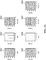
- FIGS. 2A and 2B illustrate example graphs 200a1-200a3, 200b1-200b4, 200c1-200c4, and 200d1-200d4 that provide a comparison of radon transforms on synthetic examples with a four-degree move-out difference, according to an implementation.
- Graph 200a1 shows an ideal radon transform.
- Graph 200a2 shows amplitudes of line 257a in graph 200a1.
- Graph 200a3 shows linear events.
- Graph 200b1 shows a standard radon transform.
- Graph 200b2 is an amplitude of line 257b in graph 200b1.
- Graph 200b3 shows reconstruction from a standard radon transform.
- Graph 200b4 shows a 1% data residual.
- Graph 200c1 shows a high-resolution radon transform.
- FIG. 2A illustrating graphs 200a1 -200a3
- four Ricker wavelets in graph 200a1 with 15 Hertz (Hz) dominant frequency in the radon domain generate four linear events in graph 200a3 from the linear inverse radon transform.
- Graph 200a2 shows the amplitude of the line 257a of graph 200a1 in the radon space with the time index equal to the line 257a.
- the two wavelets on the right side of the radon domain in graph 200a1 are proximate, so that the overlapping events in the middle of graph 200a3 have only four-degree dip difference. With the limited aperture range in offset, they exhibit a strong interference pattern in the time-space domain in graph 200a3.
- the standard, high-resolution and super-resolution radon transform can be compared in the experiment.
- the model obtained from different methods are listed in the first (left) column of FIGS. 2A and 2B , in which the amplitudes of lines 257a-257d, used as a time index, are presented in the second (next) column, respectively.
- the reconstructed events are shown in the third column and data residuals in the fourth column.
- Graph 200b1 is the standard radon transform result obtained by the conjugate gradient method.
- the super-resolution radon transform in graph 200d1 and the true amplitude in graph 200d2 can be obtained with three hard thresholding iterations, where each hard thresholding iteration is followed by five shrinkage iterations.
- the results are virtually identical to the model.
- the reconstructed image in graph 200d3 is accurate and, as illustrated in graph 200d4, a data residual of less than a 1%.
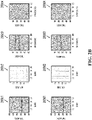
- FIGS. 3A and 3B illustrate example graphs 300a1-300a3, 300b1-300b4, 300c1-300c4, and 300d1-300d4 that illustrate a comparison of radon transform on synthetic examples with a three-degree move-out difference, according to an implementation.
- Graph 300a1 shows an ideal radon transform.
- Graph 300a2 shows amplitudes of line 357a in graph 300a1.
- Graph 300a3 shows four linear events.
- Graph 300b1 shows a standard radon transform.
- Graph 300b2 shows an amplitude of line 357b in graph 300b1.
- Graph 300b3 shows a reconstruction from a standard radon transform.
- Graph 300b4 shows a 1% data residual.
- Graph 300c1 FIG.
- 3B shows a high-resolution radon transform.
- Graph 300c2 shows an amplitude of the line 357c in graph 300c1.
- Graph 300c3 shows a reconstruction from high-resolution radon transform.
- Graph 300c4 shows a 10% data residual.
- Graph 300d1 shows a super-resolution.
- Graph 300d2 shows an amplitude of the line 357d in graph 300d1.
- Graph 300d3 shows a reconstruction from a super-resolution radon transform.
- Graph 300c4 shows a 1% data residual.
- Equation (11) the problem can be solved by adding a band-pass filter on the data to increase the dominant frequency to 30Hz; then Equation (11) will hold.
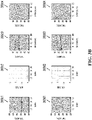
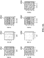
- the results obtained by the standard radon transform, high-resolution radon transform, and super-resolution radon transform are presented in graphs of FIGS. 4A and 4B as in the same order with the graphs of FIGS. 2A and 2B .
- FIGS. 4A and 4B illustrate example graphs 400a1-400a3, 400b1-400b4, 400c1-400c4, and 400d1-400d4 that illustrate a comparison of radon transform on synthetic examples with a three-degree move-out difference after filtering, according to an implementation.
- Graph 400a1 shows an ideal radon transform.
- Graph 400a2 shows amplitudes of line 457a in graph 400a1.
- Graph 400a3 shows four linear events.
- Graph 400b1 shows a standard radon transform.
- Graph 400b2 shows an amplitude of line 457b in graph 400b1.
- Graph 400b3 shows a reconstruction from a standard radon transform.
- Graph 400b4 shows a 1% data residual.
- Graph 400c1 FIG.
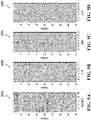
- FIGS. 5A-5D collectively illustrate an example comparison of a standard, a high-resolution, and a super-resolution radon transform on a field data example, according to an implementation.
- FIGS. 5A-5D include post-stack data 500a, a standard radon transform 500b, a high-resolution radon transform 500c, and a super-resolution radon transform 500d.
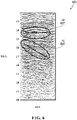
- FIG. 6 illustrates an example post-stack data set 600, according to an implementation.
- FIG. 6 contains a stacked section of a real data set, according to an implementation.
- Lines 602 and 604 indicate significant areas in the post-stack data set 600. Note that the events in the shallow part are really strong, and the large move-out differences appear from 2.3 seconds at line 602.
- Line 604 shows some dipping (tilt) layers overlapping with flat layers. After flattening the shallow part of this data, it is reasonable to assume that all the flat events that appear after 2.3 seconds are multiples. Because of the flexibility of the time domain algorithm, the radon transform space can be computed only below 2.3 seconds.
- the experiment can cut, for example, the input data into 63 vertical slices each with 50 traces ⁇ 601 time samples. Other slices with other traces and times samples can be used, and the standard radon transform and super-resolution radon transform can be applied on each slice, respectively. Since the difference in move-out decreases with offset, the narrow window would increase the difficulty to separate the multiples from primaries.
- the same automatic muting in the radon space can be applied to eliminate the multiples, and from this filtered space an inverse radon transform algorithm can be done to recover the primaries.
- FIG. 7A illustrates example primaries 700a obtained from a super-resolution radon transform, according to an implementation.
- FIG. 7B illustrates example multiples 700b obtained by subtraction, according to an implementation.
- FIGS. 7A-7B illustrate the performance of the super-resolution radon transform in separating primaries 700a from multiples 700b.
- Arrows 702a and 702b indicate significant portions of the data.
- this disclosure describes the use of a super-resolution radon transform to recover a spike-train signal with fine scales by solving a l 0 norm optimization problem.
- the algorithm combines the good feature of both greedy strategies and convex optimization approaches.
- the sparsest model in the radon domain is automatically achieved by alternatively applying the shrinkage and hard thresholding operators in the iterations.
- This super-resolution radon transform provides an interesting new approach not only to the correct reconstruction of the original signal but also to separate the signal from noise with small move-out differences. From the examples illustrated in this disclosure, the improvement in resolution can be considerable, and the performance of the super-resolution radon transform in separating primaries from multiples is superior to that of the standard radon transform.
- FIG. 10 is a flowchart illustrating an example method 1000 for performing a super-resolution radon transform on seismic data, according to an implementation.
- method 1000 may be performed, for example, by any suitable system, environment, software, and hardware, or a combination of systems, environments, software, and hardware, as appropriate.
- various steps of method 1000 can be run in parallel, in combination, in loops, or in any order.
- post-stack seismic data is received.
- the post-stack data can be the post-stack data 500a as described with reference to FIG. 5A .
- method 1000 proceeds to 1004.
- transformed seismic data is created from the received post-stack seismic data, including performing a super-resolution radon transform on the post-stack seismic data.
- the transformed seismic data that is created can be the standard radon transform 500b, the high-resolution radon transform 500c, or the super-resolution radon transform 500d as described with reference to FIGS. 5B-5D , respectively. From 1004, method 1000 proceeds to 1006.
- creating the transformed seismic data can include: applying a soft thresholding algorithm to the seismic data; subsequently applying a hard thresholding algorithm to the seismic data; repeating the applying of the soft thresholding algorithm and the hard thresholding algorithm until a threshold condition is met; and outputting a super-resolution radon domain.
- the threshold condition can be determined according to the formula: ⁇ d ⁇ Lm ⁇ 2 ⁇ d ⁇ 2 ⁇ ⁇ where d is observed data, L is an inverse linear radon transform, m is a data approximation model, and ⁇ is a predefined small positive number.
- creating the transformed seismic data includes decomposing each complex signal into a set of simple spike-train signals.
- signal and noise regions are separated using the transformed seismic data, including using a defined muting function to remove unwanted noise.
- the signal and noise regions can be separated, such as by defining and using muting function to remove some unwanted noise. From 1006, method 1000 proceeds to 1008.
- an inverse radon transform is performed using the separated signal and noise regions, outputting only signals.
- an ISTA can be used, where each iteration involves a forward and an inverse radon transform L T and L, followed by a shrinkage thresholding operator, as described with the use of Equation (4). From 1008, method 1000 stops. After 1008, method 1000 stops.
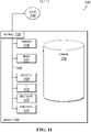
- FIG. 11 is a block diagram illustrating an example computer system 1100 used to provide computational functionalities associated with described algorithms, methods, functions, processes, flows, and procedures, as described in the instant disclosure, according to an implementation.
- the illustrated computer 1102 is intended to encompass any computing device such as a server, desktop computer, laptop/notebook computer, wireless data port, smart phone, personal data assistant (PDA), tablet computing device, one or more processors within these devices, or any other suitable processing device, including physical or virtual instances (or both) of the computing device.
- any computing device such as a server, desktop computer, laptop/notebook computer, wireless data port, smart phone, personal data assistant (PDA), tablet computing device, one or more processors within these devices, or any other suitable processing device, including physical or virtual instances (or both) of the computing device.
- PDA personal data assistant
- the computer 1102 may comprise a computer that includes an input device, such as a keypad, keyboard, touch screen, or other device that can accept user information, and an output device that conveys information associated with the operation of the computer 1102, including digital data, visual, or audio information (or a combination of information), or a graphical user interface (GUI).
- an input device such as a keypad, keyboard, touch screen, or other device that can accept user information
- an output device that conveys information associated with the operation of the computer 1102, including digital data, visual, or audio information (or a combination of information), or a graphical user interface (GUI).
- GUI graphical user interface
- the computer 1102 can serve in a role as a client, network component, a server, a database or other persistency, or any other component (or a combination of roles) of a computer system for performing the subject matter described in the instant disclosure.
- the illustrated computer 1102 is communicably coupled with a network 1130.
- one or more components of the computer 1102 may be configured to operate within environments, including cloud-computing-based, local, global, or other environment (or a combination of environments).
- the computer 1102 is an electronic computing device operable to receive, transmit, process, store, or manage data and information associated with the described subject matter. According to some implementations, the computer 1102 may also include or be communicably coupled with an application server, e-mail server, web server, caching server, streaming data server, or other server (or a combination of servers).
- an application server e-mail server, web server, caching server, streaming data server, or other server (or a combination of servers).
- the computer 1102 can receive requests over network 1130 from a client application (for example, executing on another computer 1102) and respond to the received requests by processing the received requests using an appropriate software application(s).
- requests may also be sent to the computer 1102 from internal users (for example, from a command console or by other appropriate access method), external or third-parties, other automated applications, as well as any other appropriate entities, individuals, systems, or computers.
- Each of the components of the computer 1102 can communicate using a system bus 1103.
- any or all of the components of the computer 1102 hardware or software (or a combination of both hardware and software), may interface with each other or the interface 1104 (or a combination of both), over the system bus 1103 using an application programming interface (API) 1112 or a service layer 1113 (or a combination of the API 1112 and service layer 1113).
- the API 1112 may include specifications for routines, data structures, and object classes.
- the API 1112 may be either computer-language independent or dependent and refer to a complete interface, a single function, or even a set of APIs.
- the service layer 1113 provides software services to the computer 1102 or other components (whether or not illustrated) that are communicably coupled to the computer 1102.
- the functionality of the computer 1102 may be accessible for all service consumers using this service layer.
- Software services such as those provided by the service layer 1113, provide reusable, defined functionalities through a defined interface.
- the interface may be software written in JAVA, C++, or other suitable language providing data in extensible markup language (XML) format or other suitable format.
- XML extensible markup language
- alternative implementations may illustrate the API 1112 or the service layer 1113 as stand-alone components in relation to other components of the computer 1102 or other components (whether or not illustrated) that are communicably coupled to the computer 1102.
- any or all parts of the API 1112 or the service layer 1113 may be implemented as child or sub-modules of another software module, enterprise application, or hardware module without departing from the scope of this disclosure.
- the computer 1102 includes an interface 1104. Although illustrated as a single interface 1104 in FIG. 11 , two or more interfaces 1104 may be used according to particular needs, desires, or particular implementations of the computer 1102.
- the interface 1104 is used by the computer 1102 for communicating with other systems that are connected to the network 1130 (whether illustrated or not) in a distributed environment.
- the interface 1104 comprises logic encoded in software or hardware (or a combination of software and hardware) and is operable to communicate with the network 1130. More specifically, the interface 1104 may comprise software supporting one or more communication protocols associated with communications such that the network 1130 or interface's hardware is operable to communicate physical signals within and outside of the illustrated computer 1102.
- the computer 1102 includes a processor 1105. Although illustrated as a single processor 1105 in FIG. 11 , two or more processors may be used according to particular needs, desires, or particular implementations of the computer 1102. Generally, the processor 1105 executes instructions and manipulates data to perform the operations of the computer 1102 and any algorithms, methods, functions, processes, flows, and procedures as described in the instant disclosure.
- the computer 1102 also includes a database 1106 that can hold data for the computer 1102 or other components (or a combination of both) that can be connected to the network 1130 (whether illustrated or not).
- database 1106 can be an in-memory, conventional, or other type of database storing data consistent with this disclosure.
- database 1106 can be a combination of two or more different database types (for example, a hybrid in-memory and conventional database) according to particular needs, desires, or particular implementations of the computer 1102 and the described functionality.
- two or more databases can be used according to particular needs, desires, or particular implementations of the computer 1102 and the described functionality.
- database 1106 is illustrated as an integral component of the computer 1102, in alternative implementations, database 1106 can be external to the computer 1102.
- the computer 1102 also includes a memory 1107 that can hold data for the computer 1102 or other components (or a combination of both) that can be connected to the network 1130 (whether illustrated or not).
- memory 1107 can be random access memory (RAM), read-only memory (ROM), optical, magnetic, and the like, storing data consistent with this disclosure.
- memory 1107 can be a combination of two or more different types of memory (for example, a combination of RAM and magnetic storage) according to particular needs, desires, or particular implementations of the computer 1102 and the described functionality.
- two or more memories 1107 can be used according to particular needs, desires, or particular implementations of the computer 1102 and the described functionality. While memory 1107 is illustrated as an integral component of the computer 1102, in alternative implementations, memory 1107 can be external to the computer 1102.
- the computer 1102 can also include a power supply 1114.
- the power supply 1114 can include a rechargeable or non-rechargeable battery that can be configured to be either user- or non-user-replaceable.
- the power supply 1114 can include power-conversion or management circuits (including recharging, standby, or other power management functionality).
- the power-supply 1114 can include a power plug to allow the computer 1102 to be plugged into a wall socket or other power source to, for example, power the computer 1102 or recharge a rechargeable battery.
- computers 1102 there may be any number of computers 1102 associated with, or external to, a computer system containing computer 1102, each computer 1102 communicating over network 1130.
- client the term “client,” “user,” and other appropriate terminology may be used interchangeably, as appropriate, without departing from the scope of this disclosure.
- this disclosure contemplates that many users may use one computer 1102, or that one user may use multiple computers 1102.
- the described methodology can be configured to send messages, instructions, or other communications to a computer-implemented controller, database, or other computer-implemented system to dynamically initiate control of, control, or cause another computer-implemented system to perform a computer-implemented or other function/operation.
- operations based on data, operations, outputs, or interaction with a GUI can be transmitted to cause operations associated with a computer, database, network, or other computer-based system to perform storage efficiency, data retrieval, or other operations consistent with this disclosure.
- interacting with any illustrated GUI for example, FIGS.
- 1A-1B , 2A-2B , 3A-3B , 4A-4B , 5A-5D , 6 , 7A-7B , and 8-9 ) can automatically result in one or more instructions transmitted from the GUI to trigger requests for data, storage of data, analysis of data, or other operations consistent with this disclosure.
- transmitted instructions can result in control, operation, modification, enhancement, or other operations with respect to a tangible, real-world piece of computing or other equipment.
- the described GUIs can send a request to slow or speed up a computer database magnetic/optical disk drive, shut down/activate a computing system, cause a network interface device to disable, throttle, or increase data bandwidth allowed across a network connection, or sound an audible/visual alarm (such as, a mechanical alarm/light emitting device) as a notification of a result, behavior, determination, or analysis with respect to a computing system(s) associated with the described methodology or interacting with the computing system(s) associated with the described methodology.
- an audible/visual alarm such as, a mechanical alarm/light emitting device
- the output of the described methodology can be used to dynamically influence, direct, control, influence, or manage tangible, real-world equipment related to hydrocarbon production, analysis, and recovery or for other purposes consistent with this disclosure.
- real-time data received from an ongoing drilling operation can be incorporated into an analysis performed using the described methodology.
- Output of the described super-resolution radon transform on seismic data can be used for various purposes.
- a wellbore trajectory can be modified, a drill speed can be increased or reduced, a drill can be stopped, an alarm can be activated/deactivated (such as, visual, auditory, or voice alarms), refinery or pumping operations can be affected (for example, stopped, restarted, accelerated, or reduced).
- Other examples can include alerting geo-steering and directional drilling staff based on identification of small structures and subtle stratigraphic changes in target horizons (such as, with a visual, auditory, or voice alarm).
- the described methodology can be integrated as part of a dynamic computer-implemented control system to control, influence, or use with any hydrocarbon-related or other tangible, real-world equipment consistent with this disclosure.
- Described implementations of the subject matter can include one or more features, alone or in combination.
- the first implementation includes receiving post-stack seismic data; creating, from the received post-stack seismic data, transformed seismic data, including performing a super-resolution radon transform on the post-stack seismic data; separating, using the transformed seismic data, signal and noise regions, including using a defined muting function to remove unwanted noise; and performing, using the separated signal and noise regions, an inverse radon transform on the separated signal and noise regions, and outputting only signals.
- creating the transformed seismic data includes: applying a soft thresholding algorithm to the seismic data; subsequently applying a hard thresholding algorithm to the seismic data; repeating the applying of the soft thresholding algorithm and the hard thresholding algorithm until a threshold condition is met; and outputting a super-resolution radon domain.
- the threshold condition is determined according to the formula: ⁇ d ⁇ Lm ⁇ 2 ⁇ d ⁇ 2 ⁇ ⁇ ⁇ , where d is observed data, L is an inverse linear radon transform, m is a data approximation model, and ⁇ is a predefined small positive number.
- creating the transformed seismic data includes decomposing each complex signal into a set of simple spike-train signals.
- the second implementation includes receiving post-stack seismic data; creating, from the received post-stack seismic data, transformed seismic data, including performing a super-resolution radon transform on the post-stack seismic data; separating, using the transformed seismic data, signal and noise regions, including using a defined muting function to remove unwanted noise; and performing, using the separated signal and noise regions, an inverse radon transform on the separated signal and noise regions, and outputting only signals.
- the threshold condition is determined according to the formula: ⁇ d ⁇ Lm ⁇ 2 ⁇ d ⁇ 2 ⁇ ⁇ ⁇ , where d is observed data, L is an inverse linear radon transform, m is a data approximation model, and ⁇ is a predefined small positive number.
- creating the transformed seismic data includes decomposing each complex signal into a set of simple spike-train signals.
- the third implementation includes creating the transformed seismic data includes: applying a soft thresholding algorithm to the seismic data; subsequently applying a hard thresholding algorithm to the seismic data; repeating the applying of the soft thresholding algorithm and the hard thresholding algorithm until a threshold condition is met; and outputting a super-resolution radon domain.
- creating the transformed seismic data includes: applying a soft thresholding algorithm to the seismic data; subsequently applying a hard thresholding algorithm to the seismic data; repeating the applying of the soft thresholding algorithm and the hard thresholding algorithm until a threshold condition is met; and outputting a super-resolution radon domain.
- the threshold condition is determined according to the formula: ⁇ d ⁇ Lm ⁇ 2 ⁇ d ⁇ 2 ⁇ ⁇ ⁇ , where d is observed data, L is an inverse linear radon transform, m is a data approximation model, and ⁇ is a predefined small positive number.
- creating the transformed seismic data includes decomposing each complex signal into a set of simple spike-train signals.
- Implementations of the subject matter and the functional operations described in this specification can be implemented in digital electronic circuitry, in tangibly embodied computer software or firmware, in computer hardware, including the structures disclosed in this specification and their structural equivalents, or in combinations of one or more of them.
- Software implementations of the described subject matter can be implemented as one or more computer programs, that is, one or more modules of computer program instructions encoded on a tangible, non-transitory, computer-readable medium for execution by, or to control the operation of, a computer or computer-implemented system.
- real-time means that an action and a response are temporally proximate such that an individual perceives the action and the response occurring substantially simultaneously.
- time difference for a response to display (or for an initiation of a display) of data following the individual's action to access the data can be less than 1 millisecond (ms), less than 1 second (s), or less than 5 s.
- data processing apparatus refers to data processing hardware and encompass all kinds of apparatuses, devices, and machines for processing data, including by way of example, a programmable processor, a computer, or multiple processors or computers.
- the computer can also be, or further include special-purpose logic circuitry, for example, a central processing unit (CPU), a field programmable gate array (FPGA), or an application-specific integrated circuit (ASIC).
- CPU central processing unit
- FPGA field programmable gate array
- ASIC application-specific integrated circuit
- the computer or computer-implemented system or special-purpose logic circuitry can be hardware- or software-based (or a combination of both hardware- and software-based).
- the computer can optionally include code that creates an execution environment for computer programs, for example, code that constitutes processor firmware, a protocol stack, a database management system, an operating system, or a combination of execution environments.
- code that constitutes processor firmware, a protocol stack, a database management system, an operating system, or a combination of execution environments for example, code that constitutes processor firmware, a protocol stack, a database management system, an operating system, or a combination of execution environments.
- the present disclosure contemplates the use of a computer or computer-implemented system with an operating system, for example LINUX, UNIX, WINDOWS, MAC OS, ANDROID, or IOS, or a combination of operating systems.
- a computer program which can also be referred to or described as a program, software, a software application, a unit, a module, a software module, a script, code, or other component can be written in any form of programming language, including compiled or interpreted languages, or declarative or procedural languages, and it can be deployed in any form, including, for example, as a stand-alone program, module, component, or subroutine, for use in a computing environment.
- a computer program can, but need not, correspond to a file in a file system.
- a program can be stored in a portion of a file that holds other programs or data, for example, one or more scripts stored in a markup language document, in a single file dedicated to the program in question, or in multiple coordinated files, for example, files that store one or more modules, sub-programs, or portions of code.
- a computer program can be deployed to be executed on one computer or on multiple computers that are located at one site or distributed across multiple sites and interconnected by a communication network.
- Described methods, processes, or logic flows represent one or more examples of functionality consistent with the present disclosure and are not intended to limit the disclosure to the described or illustrated implementations, but to be accorded the widest scope consistent with described principles and features.
- the described methods, processes, or logic flows can be performed by one or more programmable computers executing one or more computer programs to perform functions by operating on input data and generating output data.
- the methods, processes, or logic flows can also be performed by, and computers can also be implemented as, special-purpose logic circuitry, for example, a CPU, an FPGA, or an ASIC.
- Computers for the execution of a computer program can be based on general or special-purpose microprocessors, both, or another type of CPU.
- a CPU will receive instructions and data from and write to a memory.
- the essential elements of a computer are a CPU, for performing or executing instructions, and one or more memory devices for storing instructions and data.
- a computer will also include, or be operatively coupled to, receive data from or transfer data to, or both, one or more mass storage devices for storing data, for example, magnetic, magneto-optical disks, or optical disks.
- mass storage devices for storing data, for example, magnetic, magneto-optical disks, or optical disks.
- a computer need not have such devices.
- a computer can be embedded in another device, for example, a mobile telephone, a personal digital assistant (PDA), a mobile audio or video player, a game console, a global positioning system (GPS) receiver, or a portable memory storage device.
- PDA personal digital assistant
- GPS global positioning
- Non-transitory computer-readable media for storing computer program instructions and data can include all forms of permanent/non-permanent or volatile/non-volatile memory, media and memory devices, including by way of example semiconductor memory devices, for example, random access memory (RAM), read-only memory (ROM), phase change memory (PRAM), static random access memory (SRAM), dynamic random access memory (DRAM), erasable programmable read-only memory (EPROM), electrically erasable programmable read-only memory (EEPROM), and flash memory devices; magnetic devices, for example, tape, cartridges, cassettes, internal/removable disks; magneto-optical disks; and optical memory devices, for example, digital versatile/video disc (DVD), compact disc (CD)-ROM, DVD+/-R, DVD-RAM, DVD-ROM, high-definition/density (HD)-DVD, and BLU-RAY/BLU-RAY DISC (BD), and other optical memory technologies.
- semiconductor memory devices for example, random access memory (RAM),
- implementations of the subject matter described in this specification can be implemented on a computer having a display device, for example, a cathode ray tube (CRT), liquid crystal display (LCD), light emitting diode (LED), or plasma monitor, for displaying information to the user and a keyboard and a pointing device, for example, a mouse, trackball, or trackpad by which the user can provide input to the computer.
- a display device for example, a cathode ray tube (CRT), liquid crystal display (LCD), light emitting diode (LED), or plasma monitor
- a keyboard and a pointing device for example, a mouse, trackball, or trackpad by which the user can provide input to the computer.
- Input can also be provided to the computer using a touchscreen, such as a tablet computer surface with pressure sensitivity or a multi-touch screen using capacitive or electric sensing.
- Other types of devices can be used to interact with the user.
- feedback provided to the user can be any form of sensory feedback (such as, visual, auditory, tactile, or a combination of feedback types).
- Input from the user can be received in any form, including acoustic, speech, or tactile input.
- a computer can interact with the user by sending documents to and receiving documents from a client computing device that is used by the user (for example, by sending web pages to a web browser on a user's mobile computing device in response to requests received from the web browser).
- GUI graphical user interface
- GUI can be used in the singular or the plural to describe one or more graphical user interfaces and each of the displays of a particular graphical user interface. Therefore, a GUI can represent any graphical user interface, including but not limited to, a web browser, a touch screen, or a command line interface (CLI) that processes information and efficiently presents the information results to the user.
- a GUI can include a number of user interface (UI) elements, some or all associated with a web browser, such as interactive fields, pull-down lists, and buttons. These and other UI elements can be related to or represent the functions of the web browser.
- UI user interface
- Implementations of the subject matter described in this specification can be implemented in a computing system that includes a back-end component, for example, as a data server, or that includes a middleware component, for example, an application server, or that includes a front-end component, for example, a client computer having a graphical user interface or a Web browser through which a user can interact with an implementation of the subject matter described in this specification, or any combination of one or more such back-end, middleware, or front-end components.
- the components of the system can be interconnected by any form or medium of wireline or wireless digital data communication (or a combination of data communication), for example, a communication network.
- the computing system can include clients and servers.
- a client and server are generally remote from each other and typically interact through a communication network.
- the relationship of client and server arises by virtue of computer programs running on the respective computers and having a client-server relationship to each other.
- any claimed implementation is considered to be applicable to at least a computer-implemented method; a non-transitory, computer-readable medium storing computer-readable instructions to perform the computer-implemented method; and a computer system comprising a computer memory interoperably coupled with a hardware processor configured to perform the computer-implemented method or the instructions stored on the non-transitory, computer-readable medium.
Landscapes
- Engineering & Computer Science (AREA)
- Physics & Mathematics (AREA)
- Remote Sensing (AREA)
- Life Sciences & Earth Sciences (AREA)
- General Physics & Mathematics (AREA)
- Geology (AREA)
- Environmental & Geological Engineering (AREA)
- General Life Sciences & Earth Sciences (AREA)
- Acoustics & Sound (AREA)
- Geophysics (AREA)
- Theoretical Computer Science (AREA)
- Complex Calculations (AREA)
- Image Processing (AREA)
- Geophysics And Detection Of Objects (AREA)
- Radar Systems Or Details Thereof (AREA)
Applications Claiming Priority (4)
| Application Number | Priority Date | Filing Date | Title |
|---|---|---|---|
| US201762522525P | 2017-06-20 | 2017-06-20 | |
| US16/005,807 US10983236B2 (en) | 2017-06-20 | 2018-06-12 | Super-resolution radon transform based on thresholding |
| PCT/US2018/037237 WO2018236639A1 (en) | 2017-06-20 | 2018-06-13 | SUPER-RESOLUTION RADON TRANSFORMER BASED ON SEOUILLAGE |
| EP18738058.9A EP3642648B1 (en) | 2017-06-20 | 2018-06-13 | Super-resolution radon transform based on thresholding |
Related Parent Applications (1)
| Application Number | Title | Priority Date | Filing Date |
|---|---|---|---|
| EP18738058.9A Division EP3642648B1 (en) | 2017-06-20 | 2018-06-13 | Super-resolution radon transform based on thresholding |
Publications (1)
| Publication Number | Publication Date |
|---|---|
| EP4053597A1 true EP4053597A1 (en) | 2022-09-07 |
Family
ID=64657299
Family Applications (2)
| Application Number | Title | Priority Date | Filing Date |
|---|---|---|---|
| EP21207070.0A Withdrawn EP4053597A1 (en) | 2017-06-20 | 2018-06-13 | Super-resolution radon transform based on thresholding |
| EP18738058.9A Active EP3642648B1 (en) | 2017-06-20 | 2018-06-13 | Super-resolution radon transform based on thresholding |
Family Applications After (1)
| Application Number | Title | Priority Date | Filing Date |
|---|---|---|---|
| EP18738058.9A Active EP3642648B1 (en) | 2017-06-20 | 2018-06-13 | Super-resolution radon transform based on thresholding |
Country Status (7)
| Country | Link |
|---|---|
| US (1) | US10983236B2 (enExample) |
| EP (2) | EP4053597A1 (enExample) |
| JP (1) | JP7110246B2 (enExample) |
| CN (1) | CN111356940B (enExample) |
| CA (1) | CA3067965A1 (enExample) |
| SA (1) | SA519410836B1 (enExample) |
| WO (1) | WO2018236639A1 (enExample) |
Families Citing this family (6)
| Publication number | Priority date | Publication date | Assignee | Title |
|---|---|---|---|---|
| CN111751870B (zh) * | 2019-03-26 | 2023-02-10 | 中国石油天然气集团有限公司 | 叠后层间多次波压制方法及装置 |
| CN110471113B (zh) * | 2019-08-01 | 2020-08-04 | 中国石油大学(北京) | 基于非稳态地震资料的反演动校正方法、装置及存储介质 |
| CN115963535A (zh) * | 2021-10-09 | 2023-04-14 | 中国石油化工股份有限公司 | 地震数据线性噪音的处理方法、装置、设备及储存介质 |
| US12000971B2 (en) * | 2021-12-10 | 2024-06-04 | Saudi Arabian Oil Company | Method and system for seismic processing using virtual trace bins based on offset attributes and azimuthal attributes |
| EP4463721A4 (en) * | 2022-01-13 | 2025-12-17 | Services Petroliers Schlumberger | SOURCE SEQUENCE WITH MULTI-STAGE INVERSION WITH RADON IN THE SHOOTING AREA |
| CN115660044A (zh) * | 2022-10-14 | 2023-01-31 | 中国电信股份有限公司 | 基于拉东域稀疏表征的数据重构方法及相关设备 |
Citations (6)
| Publication number | Priority date | Publication date | Assignee | Title |
|---|---|---|---|---|
| US6636810B1 (en) * | 2002-05-24 | 2003-10-21 | Westerngeco, L.L.C. | High-resolution Radon transform for processing seismic data |
| US20100212909A1 (en) * | 2009-02-20 | 2010-08-26 | Anatoly Baumstein | Method For Analyzing Multiple Geophysical Data Sets |
| US20110147004A1 (en) * | 2007-10-17 | 2011-06-23 | Ramesh Neelamani | Method To Adapt A Template Dataset To A Target Dataset By Using Curvelet Representations |
| WO2016065356A1 (en) * | 2014-10-24 | 2016-04-28 | Ion Geophysical Corporation | Methods for seismic inversion and related seismic data processing |
| WO2016075550A1 (en) * | 2014-11-14 | 2016-05-19 | Cgg Services Sa | Device and method for weighted sparse inversion for seismic processing |
| US20160223698A1 (en) * | 2014-03-28 | 2016-08-04 | Cgg Services Sa | Noise attentuation using a dipole sparse tau-p inversion |
Family Cites Families (19)
| Publication number | Priority date | Publication date | Assignee | Title |
|---|---|---|---|---|
| US754622A (en) | 1895-12-05 | 1904-03-15 | David W Thompson | Electric clock. |
| US6574567B2 (en) * | 2001-01-23 | 2003-06-03 | Pgs Americas, Inc. | Weighted slant stack for attenuating seismic noise |
| US7239578B2 (en) * | 2005-03-03 | 2007-07-03 | John M. Robinson | Removal of noise from seismic data using radon transformations |
| US7561491B2 (en) * | 2005-03-04 | 2009-07-14 | Robinson John M | Radon transformations for removal of noise from seismic data |
| US8237138B2 (en) | 2005-09-08 | 2012-08-07 | X-Rite, Inc. | Systems and method for optical scatter imaging of latent image plates |
| FR2978273B1 (fr) | 2011-07-22 | 2013-08-09 | Thales Sa | Procede de reduction du bruit dans une sequence d'images fluoroscopiques par filtrage temporel et spatial |
| US9091788B2 (en) * | 2011-11-14 | 2015-07-28 | Cggveritas Services Sa | Device and method for de-blending simultaneous shooting data with apex shifted radon transform |
| US10317545B2 (en) | 2012-03-12 | 2019-06-11 | Schlumberger Technology Corporation | Methods and apparatus for waveform processing |
| CN102879824B (zh) | 2012-09-07 | 2015-03-04 | 清华大学 | 一种基于迭代收缩的快速稀疏Radon变换方法 |
| WO2014162300A1 (en) | 2013-04-05 | 2014-10-09 | Isis Innovation Ltd. | Acceleration of low-rank mri data acquisition |
| CN104639800B (zh) | 2013-11-08 | 2017-11-24 | 华为终端(东莞)有限公司 | 一种用于图像降噪的方法及终端 |
| CN103869364B (zh) * | 2014-03-25 | 2015-07-08 | 中国石油大学(华东) | 一种基于双项抛物拉东变换的多次波压制方法 |
| RU2568929C1 (ru) | 2014-04-30 | 2015-11-20 | Самсунг Электроникс Ко., Лтд. | Способ и система для быстрой реконструкции изображения мрт из недосемплированных данных |
| US9607362B2 (en) | 2014-05-16 | 2017-03-28 | North Carolina State University | Compressive imaging using approximate message passing with denoising |
| CN104007469A (zh) * | 2014-05-24 | 2014-08-27 | 长江大学 | 一种基于曲波变换的弱地震信号重构方法 |
| CN104730576A (zh) * | 2015-04-14 | 2015-06-24 | 吉林大学 | 基于Curvelet变换的地震信号去噪方法 |
| EP3082150B1 (en) | 2015-04-15 | 2017-07-19 | FEI Company | Method and scanning transmission type charged-particle microscope for performing tomographic imaging |
| CN104932010B (zh) * | 2015-06-09 | 2018-08-07 | 中国海洋石油集团有限公司 | 一种基于近道镶边稀疏Radon变换的绕射波分离方法 |
| CN106597539B (zh) * | 2016-12-28 | 2019-07-12 | 中国石油化工股份有限公司 | 针对黄土塬地区的曲波域Radon变换噪声压制方法 |
-
2018
- 2018-06-12 US US16/005,807 patent/US10983236B2/en active Active
- 2018-06-13 JP JP2019570885A patent/JP7110246B2/ja active Active
- 2018-06-13 EP EP21207070.0A patent/EP4053597A1/en not_active Withdrawn
- 2018-06-13 EP EP18738058.9A patent/EP3642648B1/en active Active
- 2018-06-13 CA CA3067965A patent/CA3067965A1/en active Pending
- 2018-06-13 WO PCT/US2018/037237 patent/WO2018236639A1/en not_active Ceased
- 2018-06-13 CN CN201880053080.3A patent/CN111356940B/zh not_active Expired - Fee Related
-
2019
- 2019-12-17 SA SA519410836A patent/SA519410836B1/ar unknown
Patent Citations (6)
| Publication number | Priority date | Publication date | Assignee | Title |
|---|---|---|---|---|
| US6636810B1 (en) * | 2002-05-24 | 2003-10-21 | Westerngeco, L.L.C. | High-resolution Radon transform for processing seismic data |
| US20110147004A1 (en) * | 2007-10-17 | 2011-06-23 | Ramesh Neelamani | Method To Adapt A Template Dataset To A Target Dataset By Using Curvelet Representations |
| US20100212909A1 (en) * | 2009-02-20 | 2010-08-26 | Anatoly Baumstein | Method For Analyzing Multiple Geophysical Data Sets |
| US20160223698A1 (en) * | 2014-03-28 | 2016-08-04 | Cgg Services Sa | Noise attentuation using a dipole sparse tau-p inversion |
| WO2016065356A1 (en) * | 2014-10-24 | 2016-04-28 | Ion Geophysical Corporation | Methods for seismic inversion and related seismic data processing |
| WO2016075550A1 (en) * | 2014-11-14 | 2016-05-19 | Cgg Services Sa | Device and method for weighted sparse inversion for seismic processing |
Non-Patent Citations (7)
| Title |
|---|
| AHARCHAOU M. ET AL: "A compressive sensing approach to the high-resolution linear Radon transform: application on teleseismic wavefields", GEOPHYSICAL JOURNAL INTERNATIONAL., vol. 207, no. 2, 12 August 2016 (2016-08-12), GB, pages 811 - 822, XP055946134, ISSN: 0956-540X, DOI: 10.1093/gji/ggw307 * |
| DANIEL TRAD ET AL: "Latest views of the sparse Radon transform", GEOPHYSICS, vol. 68, no. 1, 1 January 2003 (2003-01-01), US, pages 386 - 399, XP055218664, ISSN: 0016-8033, DOI: 10.1190/1.1543224 * |
| LORIS I ET AL: "Nonlinear regularization techniques for seismic tomography", JOURNAL OF COMPUTATIONAL PHYSICS, LONDON, GB, vol. 229, no. 3, 1 February 2010 (2010-02-01), pages 890 - 905, XP026907520, ISSN: 0021-9991, [retrieved on 20091017], DOI: 10.1016/J.JCP.2009.10.020 * |
| QU SHAN ET AL: "Deblending of Simultaneous-source Seismic Data using Fast Iterative Shrinkage-thresholding Algorithm with Firm-thresholding", ACTA GEOPHYSICA, VERSITA, HEIDELBERG, vol. 64, no. 4, 2 December 2016 (2016-12-02), pages 1064 - 1092, XP036120967, ISSN: 1895-6572, [retrieved on 20161202], DOI: 10.1515/ACGEO-2016-0043 * |
| WENKAI LU: "An accelerated sparse time-invariant Radon transform in the mixed frequency-time domain based on iterative 2D model shrinkage", GEOPHYSICS, SOCIETY OF EXPLORATION GEOPHYSICISTS, US, vol. 78, no. 4, 1 July 2013 (2013-07-01), pages V147 - V155, XP001583551, ISSN: 0016-8033, [retrieved on 20130705], DOI: 10.1190/GEO2012-0439.1 * |
| XIANGBO GONG ET AL: "Prestack seismic data regularization using a time-variant anisotropic Radon transform", JOURNAL OF GEOPHYSICS AND ENGINEERING, INSTITUTE OF PHYSICS PUBLISHING, BRISTOL, GB, vol. 13, no. 4, 7 June 2016 (2016-06-07), pages 462 - 469, XP020307229, ISSN: 1742-2140, [retrieved on 20160607], DOI: 10.1088/1742-2132/13/4/462 * |
| YANG PENGLIANG ET AL: "Irregularly sampled seismic data interpolation using iterative half thresholding regularization", ICASSP, IEEE INTERNATIONAL CONFERENCE ON ACOUSTICS, SPEECH AND SIGNAL PROCESSING - PROCEEDINGS 1999 IEEE, IEEE, 26 May 2013 (2013-05-26), pages 5820 - 5824, XP032507814, ISSN: 1520-6149, ISBN: 978-0-7803-5041-0, [retrieved on 20131018], DOI: 10.1109/ICASSP.2013.6638780 * |
Also Published As
| Publication number | Publication date |
|---|---|
| US10983236B2 (en) | 2021-04-20 |
| WO2018236639A1 (en) | 2018-12-27 |
| CA3067965A1 (en) | 2018-12-27 |
| US20180364383A1 (en) | 2018-12-20 |
| EP3642648B1 (en) | 2021-11-10 |
| CN111356940A (zh) | 2020-06-30 |
| JP7110246B2 (ja) | 2022-08-01 |
| SA519410836B1 (ar) | 2022-11-02 |
| EP3642648A1 (en) | 2020-04-29 |
| JP2020524286A (ja) | 2020-08-13 |
| CN111356940B (zh) | 2023-04-07 |
Similar Documents
| Publication | Publication Date | Title |
|---|---|---|
| EP3642648B1 (en) | Super-resolution radon transform based on thresholding | |
| US11092709B2 (en) | Use of wavelet cross-correlation for virtual source denoising | |
| US11243322B2 (en) | Automated system and methods for adaptive robust denoising of large-scale seismic data sets | |
| US11448784B2 (en) | Full waveform inversion using time delayed seismic data | |
| US11275190B2 (en) | Generating diffraction images based on wave equations | |
| EP3914937A1 (en) | Avo imaging condition in elastic reverse time migration | |
| US10775524B2 (en) | Simultaneous wavefield reconstruction and receiver deghosting of seismic streamer data using an L1 inversion | |
| US11340368B2 (en) | Generating a velocity model and a density model of a subsurface structure of a reservoir | |
| US11016205B2 (en) | Generating target-oriented acquisition-imprint-free prestack angle gathers using common focus point operators | |
| CA3075260A1 (en) | False image removal in reverse time migration | |
| US10983237B2 (en) | Enhancing seismic images | |
| US20190146111A1 (en) | Applying orthogonalization filtering to wavefield separation |
Legal Events
| Date | Code | Title | Description |
|---|---|---|---|
| PUAI | Public reference made under article 153(3) epc to a published international application that has entered the european phase |
Free format text: ORIGINAL CODE: 0009012 |
|
| STAA | Information on the status of an ep patent application or granted ep patent |
Free format text: STATUS: REQUEST FOR EXAMINATION WAS MADE |
|
| 17P | Request for examination filed |
Effective date: 20211109 |
|
| AC | Divisional application: reference to earlier application |
Ref document number: 3642648 Country of ref document: EP Kind code of ref document: P |
|
| AK | Designated contracting states |
Kind code of ref document: A1 Designated state(s): AL AT BE BG CH CY CZ DE DK EE ES FI FR GB GR HR HU IE IS IT LI LT LU LV MC MK MT NL NO PL PT RO RS SE SI SK SM TR |
|
| P01 | Opt-out of the competence of the unified patent court (upc) registered |
Effective date: 20230528 |
|
| STAA | Information on the status of an ep patent application or granted ep patent |
Free format text: STATUS: EXAMINATION IS IN PROGRESS |
|
| 17Q | First examination report despatched |
Effective date: 20240430 |
|
| STAA | Information on the status of an ep patent application or granted ep patent |
Free format text: STATUS: THE APPLICATION IS DEEMED TO BE WITHDRAWN |
|
| 18D | Application deemed to be withdrawn |
Effective date: 20240831 |