EP4053460B1 - Installation de chauffage de l'eau - Google Patents
Installation de chauffage de l'eau Download PDFInfo
- Publication number
- EP4053460B1 EP4053460B1 EP22157761.2A EP22157761A EP4053460B1 EP 4053460 B1 EP4053460 B1 EP 4053460B1 EP 22157761 A EP22157761 A EP 22157761A EP 4053460 B1 EP4053460 B1 EP 4053460B1
- Authority
- EP
- European Patent Office
- Prior art keywords
- line
- water
- fresh
- heat exchanger
- circulation
- Prior art date
- Legal status (The legal status is an assumption and is not a legal conclusion. Google has not performed a legal analysis and makes no representation as to the accuracy of the status listed.)
- Active
Links
- XLYOFNOQVPJJNP-UHFFFAOYSA-N water Substances O XLYOFNOQVPJJNP-UHFFFAOYSA-N 0.000 title claims description 85
- 238000010438 heat treatment Methods 0.000 title claims description 80
- 239000013505 freshwater Substances 0.000 claims description 161
- 238000011010 flushing procedure Methods 0.000 claims description 73
- 239000013529 heat transfer fluid Substances 0.000 claims description 30
- 239000003651 drinking water Substances 0.000 claims description 11
- 235000020188 drinking water Nutrition 0.000 claims description 11
- 238000000034 method Methods 0.000 claims description 7
- 244000052769 pathogen Species 0.000 description 7
- 241000589248 Legionella Species 0.000 description 6
- 208000007764 Legionnaires' Disease Diseases 0.000 description 6
- 238000002360 preparation method Methods 0.000 description 4
- 238000013517 stratification Methods 0.000 description 4
- 238000000605 extraction Methods 0.000 description 3
- 230000002349 favourable effect Effects 0.000 description 3
- 238000002156 mixing Methods 0.000 description 2
- 239000008188 pellet Substances 0.000 description 2
- 230000008569 process Effects 0.000 description 2
- 238000010926 purge Methods 0.000 description 2
- 230000001105 regulatory effect Effects 0.000 description 2
- 230000004913 activation Effects 0.000 description 1
- 239000000654 additive Substances 0.000 description 1
- 230000008901 benefit Effects 0.000 description 1
- 230000015572 biosynthetic process Effects 0.000 description 1
- 238000007599 discharging Methods 0.000 description 1
- 239000012530 fluid Substances 0.000 description 1
- 230000006870 function Effects 0.000 description 1
- 239000000203 mixture Substances 0.000 description 1
- 238000010079 rubber tapping Methods 0.000 description 1
- 238000005070 sampling Methods 0.000 description 1
- 230000007704 transition Effects 0.000 description 1
Images

Classifications
-
- F—MECHANICAL ENGINEERING; LIGHTING; HEATING; WEAPONS; BLASTING
- F24—HEATING; RANGES; VENTILATING
- F24D—DOMESTIC- OR SPACE-HEATING SYSTEMS, e.g. CENTRAL HEATING SYSTEMS; DOMESTIC HOT-WATER SUPPLY SYSTEMS; ELEMENTS OR COMPONENTS THEREFOR
- F24D17/00—Domestic hot-water supply systems
- F24D17/0078—Recirculation systems
-
- F—MECHANICAL ENGINEERING; LIGHTING; HEATING; WEAPONS; BLASTING
- F24—HEATING; RANGES; VENTILATING
- F24H—FLUID HEATERS, e.g. WATER OR AIR HEATERS, HAVING HEAT-GENERATING MEANS, e.g. HEAT PUMPS, IN GENERAL
- F24H4/00—Fluid heaters characterised by the use of heat pumps
- F24H4/02—Water heaters
- F24H4/04—Storage heaters
-
- F—MECHANICAL ENGINEERING; LIGHTING; HEATING; WEAPONS; BLASTING
- F24—HEATING; RANGES; VENTILATING
- F24D—DOMESTIC- OR SPACE-HEATING SYSTEMS, e.g. CENTRAL HEATING SYSTEMS; DOMESTIC HOT-WATER SUPPLY SYSTEMS; ELEMENTS OR COMPONENTS THEREFOR
- F24D17/00—Domestic hot-water supply systems
- F24D17/0073—Arrangements for preventing the occurrence or proliferation of microorganisms in the water
-
- F—MECHANICAL ENGINEERING; LIGHTING; HEATING; WEAPONS; BLASTING
- F24—HEATING; RANGES; VENTILATING
- F24D—DOMESTIC- OR SPACE-HEATING SYSTEMS, e.g. CENTRAL HEATING SYSTEMS; DOMESTIC HOT-WATER SUPPLY SYSTEMS; ELEMENTS OR COMPONENTS THEREFOR
- F24D3/00—Hot-water central heating systems
- F24D3/08—Hot-water central heating systems in combination with systems for domestic hot-water supply
- F24D3/082—Hot water storage tanks specially adapted therefor
-
- F—MECHANICAL ENGINEERING; LIGHTING; HEATING; WEAPONS; BLASTING
- F24—HEATING; RANGES; VENTILATING
- F24H—FLUID HEATERS, e.g. WATER OR AIR HEATERS, HAVING HEAT-GENERATING MEANS, e.g. HEAT PUMPS, IN GENERAL
- F24H15/00—Control of fluid heaters
- F24H15/10—Control of fluid heaters characterised by the purpose of the control
- F24H15/14—Cleaning; Sterilising; Preventing contamination by bacteria or microorganisms, e.g. by replacing fluid in tanks or conduits
Definitions
- the present invention relates to a water heating system for providing heated fresh water, the water heating system having a buffer storage tank and a heat source and a fresh water circulation line and a fresh water heat exchanger, and the buffer storage tank having an outer wall of the storage tank and a storage cavity surrounded by the outer wall of the storage tank, and the heat source for heating a heat transfer fluid in the
- the storage cavity is connected to the buffer storage tank and the fresh water heat exchanger is arranged in the storage cavity, the fresh water heat exchanger having a cold water inlet for connection to a drinking water supply line and a circulation water inlet and a hot water outlet, the fresh water circulation line having a circulation flow line connected to the hot water outlet and a circulation flow line connected to the circulation water inlet , Has circulation return line.
- Such water heating systems are in the prior art, for example from the DE 10 2013 112 952 A1 known. With them it is provided that the heat transfer fluid heated by a heat source in the storage cavity of the buffer storage tank fresh water in the Fresh water heat exchanger heated. The fresh water is then made available for withdrawal in a fresh water circulation line. Buffer storage tank, in which a heat exchanger is arranged in the storage cavity, for example in AT 516 383 B1 shown. Another water heating system is from the CH 706 516 A1 known.
- Fresh water circulation lines are now common in hot water preparation systems in order to ensure that warm fresh water is always available at the desired temperature at a withdrawal point for warm fresh water right at the start of the withdrawal process.
- the heated fresh water is circulated in the fresh water circulation lines.
- the object of the invention is to improve a water heating system of the type mentioned above in such a way that it can be used to ensure particularly well that no pathogens and in particular legionella can form in the fresh water heat exchanger.
- this is achieved in a water heating system of the type mentioned above in that the water heating system has a flushing line which connects the circulation flow line or the circulation return line to a flushing line connection of the fresh water heat exchanger.
- the flushing line which is designed in addition to the fresh water circulation line, it is possible and correspondingly strong heated or heated fresh water from the circulation flow line or the circulation return line via the flushing line connection in the fresh water heat exchanger, so that the areas of the fresh water heat exchanger can be flushed with correspondingly high-temperature fresh water in which, in a normal operating mode, only relatively cold or to kill the pathogens still there is insufficiently heated fresh water.
- the flushing line connection is formed directly at the cold water inlet in the fresh water heat exchanger.
- the cold water inlet is formed in an area between the flushing line connection and the circulation water inlet in the fresh water heat exchanger. Both variants ensure that the entire relevant section of the fresh water heat exchanger, in particular its entire low-temperature zone, can be flushed through with the correspondingly hot fresh water from the fresh water circulation line introduced via the flushing line and the flushing line connection.
- the heat source is connected to the buffer tank in such a way that temperature stratification is formed in the heat transfer fluid, with the heat transfer fluid having a lower temperature being located in a lower, low-temperature zone of the storage cavity. This low-temperature zone then gradually transitions into an overlying high-temperature zone, in which the heat transfer fluid is correspondingly heated or cooled. is heated.
- Water can be used as the heat transfer fluid, optionally with the additives customary in heating systems or hot water preparation systems. However, it can also be another suitable heat transfer fluid or a mixture of several heat transfer fluids.
- the buffer storage container can therefore be connected to one, but also to several, in particular several different, heat sources for heating or for heating the heat transfer fluid.
- the water heating system according to the invention can be designed in such a way that it only serves to provide heated fresh water.
- the heat transfer fluid in the storage cavity can be used not only for heating the fresh water but also for operating heating circuits such as underfloor heating, wall heating, ceiling heating or radiator heating.
- the water heating system according to the invention can therefore also be designed as a heating system with which not only heated fresh water can be provided, but also a building with corresponding heating circuits is heated.
- the heated fresh water is taken from the fresh water circulation line and must be refilled again and again into the fresh water heat exchanger via the drinking water supply line and the cold water inlet.
- Fresh water circulation lines with a corresponding circulation flow line and a corresponding circulation return line are known per se.
- at least one pump is integrated into such a fresh water circulation line in order to circulate the heated or correspondingly heated fresh water in the fresh water circulation line.
- a wide variety of extraction devices for extracting the fresh water from the fresh water circulation line are also known. For example, it can be a simple hot water tap, a mixer tap or the like.
- the storage cavity has a volume of at least 500 liters, particularly preferably at least 900 liters.
- Preferred variants of the invention provide that a lockable valve is arranged in the flushing line or between the flushing line and the circulation flow line or between the flushing line and the circulation return line. It is also favorable if in the flushing line and/or a pump is arranged in the fresh water circulation line, preferably in the circulation return line. With the appropriate pump, the necessary pressure for moving the fresh water can be provided both in the fresh water circulation line and in the flushing line. With an appropriately switchable pump and/or at least one appropriately lockable valve, however, it is also possible to use the flushing line only intermittently, i.e. from time to time, for flushing the fresh water heat exchanger with correspondingly strongly heated or heated fresh water.
- the fresh water heat exchanger is in thermally conductive contact with the heat transfer fluid in the storage cavity, so that the fresh water in the fresh water heat exchanger is heated by the heat transfer fluid.
- the fresh water heat exchanger is particularly preferably a heat exchanger line which is vertical in the storage cavity and is at least partially helical, or in other words helical.
- plate heat exchangers known per se as corresponding fresh water heat exchangers.
- the vertical extent of the fresh water heat exchanger is at least 75%, preferably at least 80%, of the vertical extent of the storage cavity. As a result, essentially the entire temperature spread in the heat transfer fluid in the storage cavity can be used to heat the fresh water in the fresh water heat exchanger.
- An inventive method for operating a water heating system provides that in a normal operating mode cold fresh water from the drinking water supply line in the fresh water heat exchanger by means of Heat transfer fluid is heated and circulated in the heated state in the fresh water circulation line and in a rinsing mode the heated fresh water is introduced from the circulation flow line or the circulation return line via the rinsing line and the rinsing line connection into the fresh water heat exchanger and passed through the fresh water heat exchanger.
- the flushing line is only activated in the flushing mode. It is not active in normal operating mode.
- the flushing mode can be activated at predetermined time intervals, for example every four hours. It is also conceivable for the time intervals to be regulated as a function of the fresh water withdrawal.
- Such an intermittent operation of the flushing line also has the particular advantage that the temperature stratification formed in the heat transfer fluid in the storage cavity is not or only slightly disturbed by the flushing operating mode.
- the fresh water introduced into the fresh water heat exchanger and passed through the fresh water heat exchanger in the flushing operating mode from the circulation flow line or the circulation return line via the flushing line and the flushing line connection has a temperature of at least 55° Celsius, preferably at least 60° Celsius.
- the entire fresh water heat exchanger must always be flushed through.
- a volume of the fresh water introduced in the flushing operating mode from the circulation flow line or the circulation return line via the flushing line and the flushing line connection into the fresh water heat exchanger and passed through the fresh water heat exchanger is at least 50%, preferably at least 65%, of a total internal volume of the fresh water heat exchanger.
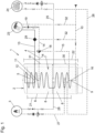
- the hot water preparation systems 1 shown schematically are designed as heating systems. That is to say, they are not only suitable for heating or heating fresh water in the fresh water heat exchanger 5 via the heat transfer fluid and discharging it via the fresh water circulation line 4 , but also for heating a building via a heating circuit 24 . As already explained at the beginning, this is not absolutely necessary.
- the invention can also be pure Act water heating system 1, in which then just no heating circuit 24 is available. In the exemplary embodiments shown, the heating circuit 24 can also be omitted.
- a heat transfer fluid 8 which is heated by the heat source 3 .
- the heat source 3 is only shown very schematically here. It can be a wide variety of types of heating boilers or other heat sources, as are known per se in the prior art. Gas boilers, oil boilers, pellet boilers, solar thermal systems, geothermal heat pumps, air heat pumps, etc. can be mentioned as examples.
- the heat source 3 can be connected to the buffer storage tank 2 in a manner known per se and in a wide variety of configurations known from the prior art for heating the heat transfer fluid 8 in the storage cavity 7 .
- the heat transfer fluid 8 is removed from the low-temperature zone 30 of the storage cavity 7 by means of the extraction line 27, fed to the heat source 3, heated or heated there and fed back into the storage cavity 7 or stratified via the feed-back line 28 at the upper end of the low-temperature zone 30.
- the withdrawal and feed points in the buffer tank 2 can be different depending on the heat source 3.
- the variant shown here is in any case favorable in terms of optimal temperature stratification of the heat transfer fluid 8 in the storage cavity 7 High-temperature zone 31 of the storage cavity 7 on.
- the valves, pumps and mixers shown in the extraction line 27 and the return line 28 can, like the entire heat source 3 and its connection to the buffer storage tank 2, be designed in different forms, as in the prior art, so that this does not need to be explained further.
- the heating circuit 24, which is basically optional as explained above, but is implemented here in this exemplary embodiment, can be, for example, underfloor heating, wall heating, ceiling heating or even radiator heating. Depending on the temperature level that is required in this heating circuit 24, the connections to the buffer tank 2 are also implemented.
- the heating flow 25 of the heating circuit 24 is connected to the upper end of the low-temperature zone 30 . From here, the heating circuit 24 removes the heat transfer fluid 8. This is then returned via the heating return 26.
- the in 1 The valves, pumps, mixers, etc. shown in the heating flow 25 and in the heating return 26 are designed as in the prior art, so that this does not have to be explained further here either.
- a plurality of heat sources 3 can be used in parallel to heat the heat transfer fluid 8 in the storage cavity 7 .
- the heat transfer fluid 8 can also be used in more than one heating circuit 24 just as well.
- the storage cavity 7 also contains the drinking water heat exchanger 5, which in this example is designed as a heat exchanger line that is vertical in the storage cavity 7 and is at least partially helical. One could also speak of a helix or a helical heat exchanger line.
- the cold water inlet 9 of the fresh water heat exchanger 5, which is connected to the drinking water supply line 10, is located at the lower end. Fresh cold drinking water is refilled into the fresh water heat exchanger 5 via the drinking water supply line 10 when heated fresh water has been removed. The heated or heated fresh water is removed via the fresh water circulation line 4 .
- This has a circulation flow line 13 and a circulation return line 14 .
- the circulation flow line 13 is connected to the hot water outlet 12 of the fresh water heat exchanger 5 .
- the circulation return line 14 opens into the fresh water heat exchanger 5 via the circulation water inlet 11 below the hot water outlet 12. Warmed or hot fresh water from the fresh water heat exchanger 5 and its hot water outlet 12 is thus fed to the hot water consumer 23 through the circulation flow line 13. If there is no consumption, this warm or heated fresh water is returned to the fresh water heat exchanger 5 via the circulation return line 14 and the circulation water inlet 11 .
- the pump 19 ensures the flow or circulation required for this.
- the valves and non-return flaps otherwise shown in the circulation return line 14 and not designated in any more detail can be designed as is known per se in the prior art.
- a mixing faucet is shown schematically as a hot water consumer 23, which mixes the warmed or heated fresh water taken from the fresh water circulation line 4 with cold fresh water from the cold water line 32 before dispensing, so that fresh water is dispensed at the desired temperature or the temperature set on the mixing faucet becomes.
- the thermal mixer 29 arranged in the circulation flow line 13 in this exemplary embodiment should also be pointed out. This is optional and is also known per se in the prior art. To avoid scalding, it ensures that water that is not too hot flows to the hot water consumer 23 . If the fresh water flowing in via the circulation flow line 13 is too hot, cold fresh water is added from the cold water line 32 connected to the thermomixer 29, so that the temperature set for the thermomixer 29 is not exceeded.
- the hot water preparation system 1 has a flushing line 15, which connects the circulation flow line 13 or the circulation return line 14 to a flushing line connection 16 of the fresh water heat exchanger 5 connects.
- the flushing line 15 according to the invention connects the circulation return line 14 to the flushing line connection 16 of the fresh water heat exchanger 5.
- a lockable valve 18 or a mixer is installed between the flushing line 15 and the circulation return line 14. This can be used to control or regulate whether warmed or heated fresh water from the circulation return line 14 is fed into the fresh water heat exchanger 5 via the flushing line 15 or not.
- the flushing line connection 16, via which the flushing line 15 opens into the fresh water heat exchanger 5, is in accordance with this exemplary embodiment 1 formed directly at the cold water inlet 9 of the fresh water heat exchanger 5 .
- Whether the entire internal volume of the fresh water heat exchanger 5 or only a partial volume of it is then flushed in the flushing operating mode can be set via the amount of warm or heated fresh water introduced via the flushing line 15 .
- the vertical extent 21 of the fresh water heat exchanger 5 is at least 75%, preferably at least 80%, of the vertical extent 22 of the storage cavity 7 is. In this normal operating mode, the flushing line 15 is out of service.
- a rinsing mode is now also provided, in which the heated or heated fresh water in the embodiment shown here according to 1 is introduced from the circulation return line 14 via the flushing line 15 and the flushing line connection 16 into the fresh water heat exchanger 5 and passed through the fresh water heat exchanger 5 .
- the water heating system 1 is operated only intermittently in time intervals in the flushing mode and between these time intervals in the normal mode.
- flushing mode of operation For example, it is conceivable to carry out the flushing mode of operation every four hours. A pure time control is therefore conceivable.
- the activation of the flushing operating mode can also be regulated just as well depending on the removal of warm or hot fresh water from the fresh water circulation line 4 .
- a volume of the fresh water introduced in the flushing operating mode from the circulation return line 14 via the flushing line 15 and the flushing line connection 16 into the fresh water heat exchanger 5 and passed through the fresh water heat exchanger 5 is at least 60%, preferably at least 75% of the total internal volume of the fresh water heat exchanger 5.
- Fresh water heat exchanger 5 introduced and passed through the fresh water heat exchanger 5 fresh water has a temperature of at least 55 ° Celsius, preferably at least 60 ° Celsius.
- 2 12 shows a second embodiment of a hot water treatment system 1 according to the invention. As already explained above, this is also designed as a heating system by adding a heating circuit 24 . In the following, however, only the differences from the first exemplary embodiment are referred to 1 received. Otherwise, the description of 1 and the first exemplary embodiment shown there.
- the flushing line 15 connects the circulation flow line 13 to the flushing line connection 16 of the fresh water heat exchanger 5 .
- a pump 20 and the shut-off valves 17 and a non-return valve 33 are additionally provided in the flushing line 15 in this exemplary embodiment.
Landscapes
- Engineering & Computer Science (AREA)
- Physics & Mathematics (AREA)
- Thermal Sciences (AREA)
- Chemical & Material Sciences (AREA)
- Combustion & Propulsion (AREA)
- Mechanical Engineering (AREA)
- General Engineering & Computer Science (AREA)
- Water Supply & Treatment (AREA)
- Heat-Pump Type And Storage Water Heaters (AREA)
- Steam Or Hot-Water Central Heating Systems (AREA)
Claims (10)
- Installation de préparation d'eau chaude (1) pour la mise à disposition d'eau potable chauffée, l'installation de préparation d'eau chaude (1) étant munie d'un ballon tampon (2) et d'une source de chaleur (3) et d'une conduite de circulation d'eau potable (4) et d'un échangeur de chaleur d'eau potable (5), et le ballon tampon (2) étant muni d'une paroi extérieure de ballon (6) et d'une cavité de ballon (7) entourée par la paroi extérieure de ballon (6), et la source de chaleur (3) étant reliée au ballon tampon (2) pour chauffer un liquide caloporteur (8) dans la cavité de ballon (7), et l'échangeur de chaleur d'eau potable (5) étant disposé dans la cavité de ballon (7), l'échangeur de chaleur d'eau potable (5) étant muni d'une entrée d'eau froide (9) pour le raccordement à une conduite d'alimentation en eau potable (10) et d'une entrée d'eau de circulation (11) et d'une sortie d'eau chaude (12), la conduite de circulation d'eau potable (4) étant munie d'une conduite d'alimentation de circulation (13) raccordée à la sortie d'eau chaude (12) et d'une conduite de retour de circulation (14) raccordée à l'entrée d'eau de circulation (11), caractérisée en ce que l'installation de préparation d'eau chaude (1) est munie d'une conduite de rinçage (15) qui relie la conduite d'alimentation de circulation (13) ou la conduite de retour de circulation (14) à un raccord de conduite de rinçage (16) de l'échangeur de chaleur d'eau potable (5).
- Installation de préparation d'eau chaude (1) selon la revendication 1, caractérisée en ce que le raccord de conduite de rinçage (16) est réalisé directement à l'entrée d'eau froide (9) dans l'échangeur de chaleur d'eau potable (5), ou l'entrée d'eau froide (9) est réalisée dans l'échangeur de chaleur d'eau potable (5) dans une zone entre le raccord de conduite de rinçage (16) et l'entrée d'eau de circulation (11).
- Installation de préparation d'eau chaude (1) selon la revendication 1 ou 2, caractérisée en ce qu'une vanne (17, 18) pouvant être fermée est disposée dans la conduite de rinçage (15) ou entre la conduite de rinçage (15) et la conduite d'alimentation de circulation (13) ou entre la conduite de rinçage (15) et la conduite de retour de circulation (14).
- Installation de préparation d'eau chaude (1) selon l'une des revendications 1 à 3, caractérisée en ce qu'une pompe (19, 20) est disposée dans la conduite de rinçage (15) et/ou dans la conduite de circulation d'eau potable (4), de préférence dans la conduite de retour de circulation (14).
- Installation de préparation d'eau chaude (1) selon l'une des revendications 1 à 4, caractérisée en ce que l'échangeur de chaleur d'eau potable (5) est réalisé sous la forme d'une conduite d'échangeur de chaleur en forme hélicoïdale au moins par endroits, placée verticalement dans la cavité de ballon (7).
- Installation de préparation d'eau chaude (1) selon l'une des revendications 1 à 5, caractérisée en ce qu'une extension verticale (21) de l'échangeur de chaleur d'eau potable (5) représente au moins 75%, de préférence au moins 80%, d'une extension verticale (22) de la cavité de ballon (7).
- Procédé de fonctionnement d'une installation de production d'eau chaude (1) selon l'une des revendications 1 à 6, dans lequel, dans un mode de fonctionnement normal, de l'eau potable froide provenant de la conduite d'alimentation en eau potable (10) est chauffée dans l'échangeur de chaleur d'eau potable (5) au moyen du liquide caloporteur (8) et circule à l'état chauffé dans la conduite de circulation d'eau potable (4) et, dans un mode de fonctionnement de rinçage, l'eau potable chauffée provenant de la conduite d'alimentation de circulation (13) ou de la conduite de retour de circulation (14) est introduite dans l'échangeur de chaleur d'eau potable (5) via la conduite de rinçage (15) et le raccord de conduite de rinçage (16), et est conduite à travers l'échangeur de chaleur d'eau potable (5).
- Procédé selon la revendication 7, caractérisé en ce que l'eau potable introduite dans l'échangeur de chaleur d'eau potable (5) en mode de fonctionnement de rinçage et provenant de la conduite d'alimentation de circulation (13) ou de la conduite de retour de circulation (14) via la conduite de rinçage (15) et le raccord de conduite de rinçage (16) et traversant l'échangeur de chaleur d'eau potable (5) présente une température d'au moins 55 °Celsius, de préférence d'au moins 60 °Celsius.
- Procédé selon la revendication 7 ou 8, caractérisé en ce qu'un volume de l'eau potable introduite dans l'échangeur de chaleur d'eau potable (5) en mode de fonctionnement de rinçage et provenant de la conduite d'alimentation de circulation (13) ou de la conduite de retour de circulation (14) via la conduite de rinçage (15) et le raccord de conduite de rinçage (16) et traversant l'échangeur de chaleur d'eau potable (5) représente au moins 60 %, de préférence au moins 75 %, d'un volume intérieur total de l'échangeur de chaleur d'eau potable (5).
- Procédé selon l'une quelconque des revendications 7 à 9, caractérisé en ce que l'installation de production d'eau chaude (1) fonctionne en mode de fonctionnement par rinçage uniquement par intermittence pendant des intervalles de temps et entre ces intervalles de temps en mode de fonctionnement normal.
Applications Claiming Priority (1)
| Application Number | Priority Date | Filing Date | Title |
|---|---|---|---|
| ATA44/2021A AT524588B1 (de) | 2021-03-03 | 2021-03-03 | Warmwasserbereitungsanlage |
Publications (3)
| Publication Number | Publication Date |
|---|---|
| EP4053460A1 EP4053460A1 (fr) | 2022-09-07 |
| EP4053460B1 true EP4053460B1 (fr) | 2023-08-23 |
| EP4053460C0 EP4053460C0 (fr) | 2023-08-23 |
Family
ID=80445970
Family Applications (1)
| Application Number | Title | Priority Date | Filing Date |
|---|---|---|---|
| EP22157761.2A Active EP4053460B1 (fr) | 2021-03-03 | 2022-02-21 | Installation de chauffage de l'eau |
Country Status (2)
| Country | Link |
|---|---|
| EP (1) | EP4053460B1 (fr) |
| AT (1) | AT524588B1 (fr) |
Family Cites Families (6)
| Publication number | Priority date | Publication date | Assignee | Title |
|---|---|---|---|---|
| DE9209198U1 (de) * | 1992-07-09 | 1992-10-01 | Höfer, Hendrik, 5340 Bad Honnef | Anlage zum Erwärmen von Wasser und zum Abtöten von Legionellen |
| DE102004033307A1 (de) * | 2003-09-05 | 2005-03-31 | Bernhard Miller | Verfahren zum Betrieb einer zentralen Warmwasserversorgungsanlage in Gebäuden |
| DE202011003668U1 (de) * | 2011-03-08 | 2011-07-14 | Noll, Thomas, Dr., 85110 | Pufferspeicher zur Aufnahme von flüssigem Medium, Wasserversorgungsanlage mit einem derartigen Pufferspeicher sowie Pufferspeichervorrichtung mit zumindest einem Pufferspeicher |
| CH706516B1 (de) * | 2012-05-15 | 2016-01-15 | Remo Meister | Verfahren zum Betrieb einer Warmwasserversorgungsanlage sowie Warmwasserversorgungsanlage zur Durchführung des Verfahrens. |
| DE102013112952A1 (de) * | 2013-11-22 | 2015-05-28 | Bernhard Löw | System und Verfahren zur Erwärmung von Trink- und Heizwasser |
| AT516383B1 (de) | 2015-02-03 | 2016-05-15 | Forstner Maximilian | Fluidspeicher |
-
2021
- 2021-03-03 AT ATA44/2021A patent/AT524588B1/de active
-
2022
- 2022-02-21 EP EP22157761.2A patent/EP4053460B1/fr active Active
Also Published As
| Publication number | Publication date |
|---|---|
| AT524588A4 (de) | 2022-07-15 |
| AT524588B1 (de) | 2022-07-15 |
| EP4053460C0 (fr) | 2023-08-23 |
| EP4053460A1 (fr) | 2022-09-07 |
Similar Documents
| Publication | Publication Date | Title |
|---|---|---|
| DE10318821B4 (de) | Verfahren zur Bereitstellung von warmem Wasser in einer Brauchwasserinstallation und Brauchwasserinstallation | |
| DE102006045651A1 (de) | Kühlgerät und Wassertank für dasselbe | |
| DE102011015196B4 (de) | Heizung zur Erwärmung von Betriebsstoffen für Fahrzeuge sowie entsprechendes Schienenfahrzeug | |
| DE102010044535B4 (de) | Warmwasserbereitungsanlage und Verfahren zum Betreiben einer Warmwasserbereitungsanlage | |
| EP4053460B1 (fr) | Installation de chauffage de l'eau | |
| EP3705789B1 (fr) | Système d'alimentation en eau et son procédé de fonctionnement | |
| DE102015118826A1 (de) | Anordnung und Verfahren zur Bereitstellung von warmem Trinkwasser mit einem Wärmeübertrager | |
| DE20300715U1 (de) | Warmwasserbereitungsanlage | |
| AT511697B1 (de) | Vorrichtung zur erwärmung von brauchwasser | |
| EP3670765B1 (fr) | Alimentation de chauffe-eau | |
| DE68910611T2 (de) | Brauchwassererhitzer. | |
| EP2339247B1 (fr) | Procédé de chauffage d'eau non potable | |
| EP3800403B1 (fr) | Procédé de fonctionnement d'un dispositif de chauffage, dispositif de chauffage | |
| EP1553353A1 (fr) | Bypass dans un conduit d'arrivée d'un réservoir de réaction | |
| AT505443B1 (de) | Vorrichtung zur entnahme von wärme aus einem wärmeträgerspeicher | |
| EP1249666B1 (fr) | Installation de chauffage | |
| DE102012024578A1 (de) | Brauchwasservorrichtung zur Speisung von Entnahmestellen mit Kalt- und Warmwasser | |
| EP2385316A1 (fr) | Ligne de recirculation pour la recirculation d'un fluide dans un système de conduites, et procédé de préparation d'une ligne de recirculation | |
| DE202022102207U1 (de) | Warmwasserversorgungssystem mit Wärmerückgewinnung | |
| DE20217305U1 (de) | Desinfektion des gesamten Zirkulations-Volumenstromes | |
| DE8111726U1 (de) | Pufferspeicher fuer eine anlage zur beheizung von gebaeuden und zur erwaermung von brauchwasser | |
| WO2016005109A1 (fr) | Dispositif de traitement thermique et procédé de traitement thermique | |
| DE102015101896B4 (de) | Verfahren zur Steuerung einer Behandlungsanlage, insbesondere einer Behandlungsanlage zum Erhitzen von Produkten, sowie Behandlungsanlage | |
| DE3123253C2 (de) | Verfahren zum Erwärmen und Speichern einer Flüssigkeit, insbesondere von Brauchwasser | |
| DE102007009198B4 (de) | Wasserspeicher |
Legal Events
| Date | Code | Title | Description |
|---|---|---|---|
| PUAI | Public reference made under article 153(3) epc to a published international application that has entered the european phase |
Free format text: ORIGINAL CODE: 0009012 |
|
| STAA | Information on the status of an ep patent application or granted ep patent |
Free format text: STATUS: THE APPLICATION HAS BEEN PUBLISHED |
|
| AK | Designated contracting states |
Kind code of ref document: A1 Designated state(s): AL AT BE BG CH CY CZ DE DK EE ES FI FR GB GR HR HU IE IS IT LI LT LU LV MC MK MT NL NO PL PT RO RS SE SI SK SM TR |
|
| STAA | Information on the status of an ep patent application or granted ep patent |
Free format text: STATUS: REQUEST FOR EXAMINATION WAS MADE |
|
| 17P | Request for examination filed |
Effective date: 20221214 |
|
| RBV | Designated contracting states (corrected) |
Designated state(s): AL AT BE BG CH CY CZ DE DK EE ES FI FR GB GR HR HU IE IS IT LI LT LU LV MC MK MT NL NO PL PT RO RS SE SI SK SM TR |
|
| GRAP | Despatch of communication of intention to grant a patent |
Free format text: ORIGINAL CODE: EPIDOSNIGR1 |
|
| STAA | Information on the status of an ep patent application or granted ep patent |
Free format text: STATUS: GRANT OF PATENT IS INTENDED |
|
| RIC1 | Information provided on ipc code assigned before grant |
Ipc: F24H 15/14 20220101ALI20230130BHEP Ipc: F24D 17/00 20060101AFI20230130BHEP |
|
| INTG | Intention to grant announced |
Effective date: 20230220 |
|
| GRAJ | Information related to disapproval of communication of intention to grant by the applicant or resumption of examination proceedings by the epo deleted |
Free format text: ORIGINAL CODE: EPIDOSDIGR1 |
|
| STAA | Information on the status of an ep patent application or granted ep patent |
Free format text: STATUS: REQUEST FOR EXAMINATION WAS MADE |
|
| GRAP | Despatch of communication of intention to grant a patent |
Free format text: ORIGINAL CODE: EPIDOSNIGR1 |
|
| STAA | Information on the status of an ep patent application or granted ep patent |
Free format text: STATUS: GRANT OF PATENT IS INTENDED |
|
| INTC | Intention to grant announced (deleted) | ||
| INTG | Intention to grant announced |
Effective date: 20230515 |
|
| GRAS | Grant fee paid |
Free format text: ORIGINAL CODE: EPIDOSNIGR3 |
|
| GRAA | (expected) grant |
Free format text: ORIGINAL CODE: 0009210 |
|
| STAA | Information on the status of an ep patent application or granted ep patent |
Free format text: STATUS: THE PATENT HAS BEEN GRANTED |
|
| AK | Designated contracting states |
Kind code of ref document: B1 Designated state(s): AL AT BE BG CH CY CZ DE DK EE ES FI FR GB GR HR HU IE IS IT LI LT LU LV MC MK MT NL NO PL PT RO RS SE SI SK SM TR |
|
| REG | Reference to a national code |
Ref country code: GB Ref legal event code: FG4D Free format text: NOT ENGLISH |
|
| REG | Reference to a national code |
Ref country code: CH Ref legal event code: EP |
|
| REG | Reference to a national code |
Ref country code: DE Ref legal event code: R096 Ref document number: 502022000094 Country of ref document: DE |
|
| REG | Reference to a national code |
Ref country code: IE Ref legal event code: FG4D Free format text: LANGUAGE OF EP DOCUMENT: GERMAN |
|
| REG | Reference to a national code |
Ref country code: LT Ref legal event code: MG9D |
|
| REG | Reference to a national code |
Ref country code: NL Ref legal event code: MP Effective date: 20230823 |
|
| PG25 | Lapsed in a contracting state [announced via postgrant information from national office to epo] |
Ref country code: GR Free format text: LAPSE BECAUSE OF FAILURE TO SUBMIT A TRANSLATION OF THE DESCRIPTION OR TO PAY THE FEE WITHIN THE PRESCRIBED TIME-LIMIT Effective date: 20231124 |
|
| PG25 | Lapsed in a contracting state [announced via postgrant information from national office to epo] |
Ref country code: IS Free format text: LAPSE BECAUSE OF FAILURE TO SUBMIT A TRANSLATION OF THE DESCRIPTION OR TO PAY THE FEE WITHIN THE PRESCRIBED TIME-LIMIT Effective date: 20231223 |
|
| PG25 | Lapsed in a contracting state [announced via postgrant information from national office to epo] |
Ref country code: RS Free format text: LAPSE BECAUSE OF FAILURE TO SUBMIT A TRANSLATION OF THE DESCRIPTION OR TO PAY THE FEE WITHIN THE PRESCRIBED TIME-LIMIT Effective date: 20230823 Ref country code: NO Free format text: LAPSE BECAUSE OF FAILURE TO SUBMIT A TRANSLATION OF THE DESCRIPTION OR TO PAY THE FEE WITHIN THE PRESCRIBED TIME-LIMIT Effective date: 20231123 Ref country code: IS Free format text: LAPSE BECAUSE OF FAILURE TO SUBMIT A TRANSLATION OF THE DESCRIPTION OR TO PAY THE FEE WITHIN THE PRESCRIBED TIME-LIMIT Effective date: 20231223 Ref country code: HR Free format text: LAPSE BECAUSE OF FAILURE TO SUBMIT A TRANSLATION OF THE DESCRIPTION OR TO PAY THE FEE WITHIN THE PRESCRIBED TIME-LIMIT Effective date: 20230823 Ref country code: GR Free format text: LAPSE BECAUSE OF FAILURE TO SUBMIT A TRANSLATION OF THE DESCRIPTION OR TO PAY THE FEE WITHIN THE PRESCRIBED TIME-LIMIT Effective date: 20231124 |
|
| U01 | Request for unitary effect filed |
Effective date: 20230904 |
|
| U07 | Unitary effect registered |
Designated state(s): AT BE BG DE DK EE FI FR IT LT LU LV MT NL PT SE SI Effective date: 20240105 |
|
| PG25 | Lapsed in a contracting state [announced via postgrant information from national office to epo] |
Ref country code: PL Free format text: LAPSE BECAUSE OF FAILURE TO SUBMIT A TRANSLATION OF THE DESCRIPTION OR TO PAY THE FEE WITHIN THE PRESCRIBED TIME-LIMIT Effective date: 20230823 |
|
| U20 | Renewal fee paid [unitary effect] |
Year of fee payment: 3 Effective date: 20240215 |
|
| PG25 | Lapsed in a contracting state [announced via postgrant information from national office to epo] |
Ref country code: ES Free format text: LAPSE BECAUSE OF FAILURE TO SUBMIT A TRANSLATION OF THE DESCRIPTION OR TO PAY THE FEE WITHIN THE PRESCRIBED TIME-LIMIT Effective date: 20230823 |
|
| PG25 | Lapsed in a contracting state [announced via postgrant information from national office to epo] |
Ref country code: SM Free format text: LAPSE BECAUSE OF FAILURE TO SUBMIT A TRANSLATION OF THE DESCRIPTION OR TO PAY THE FEE WITHIN THE PRESCRIBED TIME-LIMIT Effective date: 20230823 Ref country code: RO Free format text: LAPSE BECAUSE OF FAILURE TO SUBMIT A TRANSLATION OF THE DESCRIPTION OR TO PAY THE FEE WITHIN THE PRESCRIBED TIME-LIMIT Effective date: 20230823 Ref country code: ES Free format text: LAPSE BECAUSE OF FAILURE TO SUBMIT A TRANSLATION OF THE DESCRIPTION OR TO PAY THE FEE WITHIN THE PRESCRIBED TIME-LIMIT Effective date: 20230823 Ref country code: CZ Free format text: LAPSE BECAUSE OF FAILURE TO SUBMIT A TRANSLATION OF THE DESCRIPTION OR TO PAY THE FEE WITHIN THE PRESCRIBED TIME-LIMIT Effective date: 20230823 Ref country code: SK Free format text: LAPSE BECAUSE OF FAILURE TO SUBMIT A TRANSLATION OF THE DESCRIPTION OR TO PAY THE FEE WITHIN THE PRESCRIBED TIME-LIMIT Effective date: 20230823 |
|
| REG | Reference to a national code |
Ref country code: DE Ref legal event code: R097 Ref document number: 502022000094 Country of ref document: DE |
|
| PLBE | No opposition filed within time limit |
Free format text: ORIGINAL CODE: 0009261 |
|
| STAA | Information on the status of an ep patent application or granted ep patent |
Free format text: STATUS: NO OPPOSITION FILED WITHIN TIME LIMIT |
|
| 26N | No opposition filed |
Effective date: 20240524 |