EP4053071B1 - Assistenzsysteme und -verfahren für ein materialhandhabungsfahrzeug - Google Patents
Assistenzsysteme und -verfahren für ein materialhandhabungsfahrzeug Download PDFInfo
- Publication number
- EP4053071B1 EP4053071B1 EP22160158.6A EP22160158A EP4053071B1 EP 4053071 B1 EP4053071 B1 EP 4053071B1 EP 22160158 A EP22160158 A EP 22160158A EP 4053071 B1 EP4053071 B1 EP 4053071B1
- Authority
- EP
- European Patent Office
- Prior art keywords
- mhv
- material handling
- operator
- handling vehicle
- assistance device
- Prior art date
- Legal status (The legal status is an assumption and is not a legal conclusion. Google has not performed a legal analysis and makes no representation as to the accuracy of the status listed.)
- Active
Links
Images


Classifications
-
- B—PERFORMING OPERATIONS; TRANSPORTING
- B66—HOISTING; LIFTING; HAULING
- B66F—HOISTING, LIFTING, HAULING OR PUSHING, NOT OTHERWISE PROVIDED FOR, e.g. DEVICES WHICH APPLY A LIFTING OR PUSHING FORCE DIRECTLY TO THE SURFACE OF A LOAD
- B66F9/00—Devices for lifting or lowering bulky or heavy goods for loading or unloading purposes
- B66F9/06—Devices for lifting or lowering bulky or heavy goods for loading or unloading purposes movable, with their loads, on wheels or the like, e.g. fork-lift trucks
- B66F9/075—Constructional features or details
- B66F9/20—Means for actuating or controlling masts, platforms, or forks
- B66F9/24—Electrical devices or systems
-
- B—PERFORMING OPERATIONS; TRANSPORTING
- B66—HOISTING; LIFTING; HAULING
- B66F—HOISTING, LIFTING, HAULING OR PUSHING, NOT OTHERWISE PROVIDED FOR, e.g. DEVICES WHICH APPLY A LIFTING OR PUSHING FORCE DIRECTLY TO THE SURFACE OF A LOAD
- B66F9/00—Devices for lifting or lowering bulky or heavy goods for loading or unloading purposes
- B66F9/06—Devices for lifting or lowering bulky or heavy goods for loading or unloading purposes movable, with their loads, on wheels or the like, e.g. fork-lift trucks
- B66F9/075—Constructional features or details
- B66F9/07581—Remote controls
-
- B—PERFORMING OPERATIONS; TRANSPORTING
- B66—HOISTING; LIFTING; HAULING
- B66F—HOISTING, LIFTING, HAULING OR PUSHING, NOT OTHERWISE PROVIDED FOR, e.g. DEVICES WHICH APPLY A LIFTING OR PUSHING FORCE DIRECTLY TO THE SURFACE OF A LOAD
- B66F9/00—Devices for lifting or lowering bulky or heavy goods for loading or unloading purposes
- B66F9/06—Devices for lifting or lowering bulky or heavy goods for loading or unloading purposes movable, with their loads, on wheels or the like, e.g. fork-lift trucks
- B66F9/075—Constructional features or details
- B66F9/0755—Position control; Position detectors
-
- G—PHYSICS
- G05—CONTROLLING; REGULATING
- G05D—SYSTEMS FOR CONTROLLING OR REGULATING NON-ELECTRIC VARIABLES
- G05D1/00—Control of position, course, altitude or attitude of land, water, air or space vehicles, e.g. using automatic pilots
- G05D1/0011—Control of position, course, altitude or attitude of land, water, air or space vehicles, e.g. using automatic pilots associated with a remote control arrangement
- G05D1/0038—Control of position, course, altitude or attitude of land, water, air or space vehicles, e.g. using automatic pilots associated with a remote control arrangement by providing the operator with simple or augmented images from one or more cameras located onboard the vehicle, e.g. tele-operation
-
- G—PHYSICS
- G05—CONTROLLING; REGULATING
- G05D—SYSTEMS FOR CONTROLLING OR REGULATING NON-ELECTRIC VARIABLES
- G05D1/00—Control of position, course, altitude or attitude of land, water, air or space vehicles, e.g. using automatic pilots
- G05D1/0011—Control of position, course, altitude or attitude of land, water, air or space vehicles, e.g. using automatic pilots associated with a remote control arrangement
- G05D1/0044—Control of position, course, altitude or attitude of land, water, air or space vehicles, e.g. using automatic pilots associated with a remote control arrangement by providing the operator with a computer generated representation of the environment of the vehicle, e.g. virtual reality, maps
-
- G—PHYSICS
- G05—CONTROLLING; REGULATING
- G05D—SYSTEMS FOR CONTROLLING OR REGULATING NON-ELECTRIC VARIABLES
- G05D1/00—Control of position, course, altitude or attitude of land, water, air or space vehicles, e.g. using automatic pilots
- G05D1/02—Control of position or course in two dimensions
- G05D1/021—Control of position or course in two dimensions specially adapted to land vehicles
- G05D1/0231—Control of position or course in two dimensions specially adapted to land vehicles using optical position detecting means
- G05D1/0234—Control of position or course in two dimensions specially adapted to land vehicles using optical position detecting means using optical markers or beacons
-
- G—PHYSICS
- G06—COMPUTING OR CALCULATING; COUNTING
- G06F—ELECTRIC DIGITAL DATA PROCESSING
- G06F3/00—Input arrangements for transferring data to be processed into a form capable of being handled by the computer; Output arrangements for transferring data from processing unit to output unit, e.g. interface arrangements
- G06F3/01—Input arrangements or combined input and output arrangements for interaction between user and computer
- G06F3/011—Arrangements for interaction with the human body, e.g. for user immersion in virtual reality
- G06F3/013—Eye tracking input arrangements
-
- G—PHYSICS
- G09—EDUCATION; CRYPTOGRAPHY; DISPLAY; ADVERTISING; SEALS
- G09B—EDUCATIONAL OR DEMONSTRATION APPLIANCES; APPLIANCES FOR TEACHING, OR COMMUNICATING WITH, THE BLIND, DEAF OR MUTE; MODELS; PLANETARIA; GLOBES; MAPS; DIAGRAMS
- G09B9/00—Simulators for teaching or training purposes
-
- G—PHYSICS
- G09—EDUCATION; CRYPTOGRAPHY; DISPLAY; ADVERTISING; SEALS
- G09B—EDUCATIONAL OR DEMONSTRATION APPLIANCES; APPLIANCES FOR TEACHING, OR COMMUNICATING WITH, THE BLIND, DEAF OR MUTE; MODELS; PLANETARIA; GLOBES; MAPS; DIAGRAMS
- G09B9/00—Simulators for teaching or training purposes
- G09B9/02—Simulators for teaching or training purposes for teaching control of vehicles or other craft
- G09B9/04—Simulators for teaching or training purposes for teaching control of vehicles or other craft for teaching control of land vehicles
- G09B9/042—Simulators for teaching or training purposes for teaching control of vehicles or other craft for teaching control of land vehicles providing simulation in a real vehicle
Definitions
- a human operator 30 may be replaced with an automated controller to comprise a fully-automated system (i.e., an autonomously guided material handling vehicle).
- the wearable device may include an image display 74 close enough to an eye of an operator 30 such that a displayed image fills or nearly fills a field of view associated with the eye, and appears as a normal sized image, such as might be displayed on a traditional display.
- the relevant technology may be referred to as "near-eye displays.”
- the training reinforcement assistance device 38 may be configured as, for example, eyeglasses, goggles, a helmet, a hat, a visor, a headband, or in some other form that can be supported on or from a head of the operator 30.
- the training reinforcement assistance device 38 may be further configured to display images to both eyes of the operator 30. Alternatively, the training reinforcement assistance device 38 may display images to only one eye, either a left eye or a right eye.
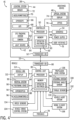
- the training reinforcement assistance device 38 may further include the operator interface 51 for providing information to the operator 30 or receiving input from the operator 30.
- the operator interface 51 may be associated with, for example, displayed images, a touchpad, a keypad, buttons, a microphone, and/or other peripheral input devices.
- the controller 50 may control functions of the training reinforcement assistance device 38 based on input received through the operator interface 51. For example, the controller 50 may utilize an operator input from the operator interface 51 to control how the training reinforcement assistance device 38 may display images within a field of view or may determine what images the training reinforcement assistance device 38 may display.
- the eye-tracking system 42 may track a path associated with the eye or the eye pupil movement.
- the controller 50 can receive the information associated with the path associated with the eye movement from the eye-tracking system 42 and update the location of the virtual image based on the operator's eye direction.
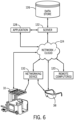
- the MHV 10, the training reinforcement assistance device 38, and/or a remote computer 120 may be communicatively coupled with one or more remote sites such as a remote server 122 via a network/cloud 124.
- the network/cloud 124 represents one or more systems by which the MHV 10, the training reinforcement assistance device 38, and/or the remote computer 120 may communicate with the remote server 122.
- the network/cloud 124 may be one or more of various wired or wireless communication mechanisms, including any desired combination of wired and/or wireless communication mechanisms and any desired network topology (or topologies when multiple communication mechanisms are utilized).
- the system 41 may combine combinations of events into tasks. For example, “pick load from floor” followed by “place load at height” may constitute a single pallet 36 being put away from a floor location to the rack. Alternatively, “pick load from height” followed by “place load on floor” may constitute taking a pallet 36 down from the rack. This data can be converted into productivity metrics and communicated to the server.
- the server 122 can also generally implement features that may enable the MHV 10 and/or the training reinforcement assistance device 38 to communicate with cloud-based applications 128.
- Communications from the MHV 10 can be directed through the network/cloud 124 to the server 122 and/or cloud-based applications 128 with or without a networking device 132, such as a router and/or modem.
- a networking device 132 such as a router and/or modem.
- communications from the cloud-based applications 128, even though these communications may indicate one of the MHV 10 and/or the remote computer 120 as an intended recipient can also be directed to the server 122.
- the cloud-based applications 128 are generally any appropriate services or applications 128 that are accessible through any part of the network/cloud 124 and may be capable of interacting with the MHV 10 and/or the remote computer 120.
- the training reinforcement assistance device 38 can be feature-rich with respect to communication capabilities, i.e., have built-in capabilities to access the network/cloud 124 and any of the cloud-based applications 128 or can be loaded with, or programmed to have, such capabilities.
- the training reinforcement assistance device 38 can also access any part of the network/cloud 124 through industry standard wired or wireless access points, cell phone cells, or network nodes.
- operators 30 can register to use the remote server 122 through the training reinforcement assistance device 38, which may provide access to the MHV 10 and/or the remote computer 120 and/or thereby allow the server 122 to communicate directly or indirectly with the MHV 10 and/or the remote computer 120.
- the server 122 can be upgraded to be able to receive communications for the new cloud-based application 128 and to translate communications between the new protocol and the protocol used by the MHV 10 and/or the remote computer 120.
- the flexibility, scalability, and upgradeability of current server technology render the task of adding new cloud-based application protocols to the server 122 relatively quick and easy.
- the training reinforcement assistance device 38 may also be utilized for performance tracking and the training reinforcement assistance device 38 can allow for passive monitoring of performance without requiring any effort on the part of the operator 30. This can improve accuracy and does not take the operator 30 away from productive activities.
- the training reinforcement assistance device 38 may store images (or videos) from the imager 72 and/or images (or videos) may be sent to the cloud and stored on the server. The videos may provide a live feed or a previous task that can provide insight of a task or maneuver of the MHV 10.
- the training reinforcement assistance device 38 can also assess how much time the operator 30 spends in each step of the load handling process (traveling, lifting, side shifting forks 24, multiple attempts to align the forks 24, etc.) or any other data. A warehouse manager can use this information to benchmark the operator 30 against their peers and identify which operators 30 could use additional training and in which areas.
- the compiled data can be utilized to provide focused training to operators 30 to improve their skills.
- Engineered labor standards can be created for each pallet 36 move given the starting and ending locations to normalize the variable level of effort required for each move.
- the compiled data and analysis thereof can provide a metric of operator performance while also being able to capture variable or random events during the operator's shift that affect productivity but are difficult to capture and quantify. For example, waiting at intersections, waiting for pedestrians, and waiting for other vehicles 10 may occur during operation, but may be considered non-value-add tasks that can be recorded and optimized.
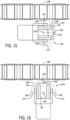
- fiducials or fiducial markers 78 may be positioned on the MHV 10.
- the MHV 10 can communicate parameters about its geometry to the training reinforcement assistance device 38, including the fiducials 78 relative to the vehicle body 12.
- the fiducials 78 may be configured as one or more barcodes that encode the static vehicle geometry information and communicate it to the training reinforcement assistance device 38.
- using the one or more barcodes may encode a unique vehicle ID that can be cross referenced in a database to look up the relevant static vehicle information.
- the MHV 10 can communicate its unique ID, steer angle, and speed to a central server.
- anyone with a training reinforcement assistance device 38 can look at the MHV 10, read the unique ID, and see its projected path overlaid on their view as oriented relative to that MHV 10.
- remote operators 30 may also connect to a specific training reinforcement assistance device 38 and MHV 10 combination and be able to remotely view the working environment from the training reinforcement assistance device 38 through the imager 72 and/or the overlaid image produced by the training reinforcement assistance device 38 and seen by the operator 30 of the MHV 10.
- the remote viewer may also alter various functions of the training reinforcement assistance device 38 and/or the MHV 10 through the remote computer 120.
- control unit 82 and/or the network/cloud 124 may communicate additional information about the MHV 10 to the controller 50 of the training reinforcement assistance device 38, such as the wheelbase, overall width, and so on.
- the MHV 10 may also communicate vehicle kinematic information, such as a steering angle or propulsion drive system 106 conditions to the controller 50.
- the controller 50 may provide instructions to the display 74 for providing a virtual image in a predefined location.
- the predefined location may also consider the pupil axis of the operator 30 as sensed by the eye-tracking system 42.
- the virtual image may be configured as an overlaid image that is presented to the operator 30 that includes static and/or dynamic locus lines 130 to aid the operator 30 in maneuvering the MHV 10 to a target location.
- the steering angle sensor 100 can send steering wheel angle data to the control unit 82 and/or the controller 50.
- the controller 50 may analyze the data coming from the steering angle sensor 100, along with other vehicle data, including the gear ratio, wheel base size, wheel radius, and vehicle speed data, and calculate a size and direction for the static and/or dynamic locus lines 130 to be displayed as an overlay on the display 74.
- the overlaid image may be configured as one or more dynamic and/or static locus lines 130.
- the locus lines 130 includes a first line 130a that is generally aligned with a center longitudinal axis of the MHV 10 (see, e.g., Fig. 7 ).
- the first line 130a may be arranged between the forks 24.
- the locus lines 130 may include the first line 130a and a pair of outer lines 130b that generally align with an outer width of the body 12 of the MHV 10 (or a predefined distance outwardly of the body 12) (see, e.g., Fig. 8 ).
- the pair of outer lines 130b may defined the same shape, direction, and length as the first line 130a.
- the dynamic locus lines 130 displayed can have a direction that may be determined in response to a change in the steering wheel angle and other vehicle data related to wheel base, radius, and gear ratio.
- Each step of calculating dynamic locus lines 130 can depend on the turning radius and the current steering wheel angle of the MHV 10, so the locus lines 130 can change as the steering wheel angle is changed.
- the dynamic locus lines 130 can display a true path of the MHV 10 so that the operator 30 can get a sense of where the MHV 10 is headed as they turn the steering wheel and approach their desired destination.
- "dynamic locus lines” means that the locus lines 130 may be updated based on the changed vehicle position and/or kinematics.
- the length of the locus lines 130 may also be adjusted accordingly. For example, as the steering wheel is turned away from center, the locus line length may be increased. As the steering wheel is turned towards center, the locus lines 130 may be decreased in length.
- the dynamic locus lines 130 have a maximum length at a steering wheel angle that is furthest from center and a minimum length at a steering wheel angle that is at center.
- the controller 50 can recalculate and display the dynamic locus lines 130 at the adjusted angle and length. At a maximum angle, either left or right of center, the locus lines 130 can extend to a maximum length dimension.
- the dynamic locus lines 130 can provide the accurate projected vehicle path.
- the operator 30 can be provided a true indication of where the MHV 10 is headed based on the steering wheel angle position and the vehicle wheel base information.
- the true vehicle path as opposed to a vehicle path to a target, can provide the operator 30 with the ability to reach a desired location, knowing the direction the MHV 10 is headed by the locus lines 130 displayed on the display 74, which can be provided as an overlaid image 140.
- additional factors such as wheel slippage, tire wear, tire deformation, load and/or battery weight, tolerances in steer angle measurement, or vehicle maintenance or repair may also be sensed by one or more sensors of the MHV 10 and/or the additional vehicle data may be manually inputted to further update the locus lines 130.
- a first locus line 130 in the center of the vehicle's path can be projected through the training reinforcement assistance device 38 for the operator 30 to reference (see, e.g., Fig. 7 ).
- a pair of locus lines 130 may be provided on the display 74 as an overlay that indicate the path of the vehicle's envelope plus a margin can be positioned in real space relative to the known geometry of the MHV 10 as communicated to the training reinforcement assistance device 38 by the fiducials 78 on the MHV 10.
- the MHV 10 includes fiducials 78 arranged on the vehicle body 12 of the MHV 10.
- the fiducials 78 include four fiducials 78 arranged on the vehicle body 12.
- the MHV 10 may include more or less than four fiducials 78.
- the fiducials 78 are arranged on a first operator-facing surface or structure 79 of the vehicle body 12. That is, the fiducials 78 are arranged on a first operator-facing surface 79 of the vehicle body 12 that are visible by the camera 62 and/or the imager 72, when an operator's field of view is directed in a first or forward travel direction (e.g., a direction toward the forks 24).
- the MHV 10 may be operated in more than one direction. Additionally, the turning characteristics of the MHV 10 in each operating direction may be known and predictable given the vehicle's geometry, steer angle, among other kinematics. With this information, a turning radius of the MHV 10 can be determined and communicated to the operator so they better understand the path the MHV 10 may take while operating in a first direction or a second opposing direction. Accordingly, the MHV 10 includes a fiducial 78 positioned in various locations that allow for the training reinforcement assistance device 38 to determine a direction of the training reinforcement assistance device 38 relative to the MHV 10 based on the fiducials 78 recognized by the training reinforcement assistance device 38 through the imager 72.
- the MHV 10 includes the fiducials 78 arranged on the first operator-facing surface 79 (see, e.g., Figs. 7 and 8 ), and includes additional fiducials 78 arranged on a second operator-facing surface or structure 81 of the vehicle body 12.
- the fiducials 78 arranged on the second operator-facing surface 81 are visible by the camera 62 and/or the imager 72, when an operator's field of view is directed in a second or reverse travel direction (e.g., a direction away from the forks 24).
- the training reinforcement assistance device 38 may utilize any other component therein for determining a direction and position of the training reinforcement assistance device 38 relative to the MHV 10.
- the controller 50, the control unit 82, and/or a remote server may include machine learning algorithms that can be used to identify the position of the MHV 10 relative to the training reinforcement assistance device 38 based on inputs from the training reinforcement assistance device 38 and/or the MHV 10.
- the position of the training reinforcement assistance device 38 relative to the vehicle body 12 can be calculated so that the vehicle path (i.e., the locus lines 130) can be overlaid through the optical system 46 while considering various vehicle driving conditions, such as steer angle, vehicle speed and direction, etc.
- the controller 50 of the training reinforcement assistance device 38, the control unit 82 of the MHV 10, and/or a remote database may perform various calculations to determine the locus lines 130 to project and transform the image 140 to provide the correct perspective for the operator 30 such that the operator 30 sees the locus lines 130 projected where the MHV 10 is expected to go based on the current vehicle conditions and/or operator position.
- operators 30 may be able to see a projected path of the MHV 10 as indicated by one or more locus lines 130, which may assist in guidance of the MHV 10 as the operator is learning the driving characteristics of the MHV, for example during training, whether or not they are familiar with the driving characteristics of the MHV 10.
- various operators 30 can see the projected path of the MHV 10 and more efficiently learn to maneuver the MHV 10 for performing a task, such as picking or placing loads.
- an image 140 or hologram is overlaid over the work element, such as the forks 24, of the MHV 10 to aid the operator 30 in aligning the MHV 10 with a predefined location, such as openings of a pallet 36.
- the overlaid image 140 can serve as a jig for the operator 30 to be able to position the MHV 10 in the predefined location to handle loads and minimize aisle width requirements.
- the driver assistance system 41 provided herein may temporarily control steering during a right-angle stacking event after the operator 30 has positioned the MHV 10 appropriately.
- the operator 30 can control the throttle and the MHV 10 can automatically manipulate the steer angle so that the MHV 10 takes an idealized path to complete a task, such as picking up or depositing a load. In any fashion, the operator 30 can remain in control of the MHV 10 during performance of any actions.
- the MHV 10 can provide the position of the forks 24 to the training reinforcement assistance device 38, including height, tilt, side shift, and reach relative to the vehicle's body 12. Additionally or alternatively, the MHV 10 may also communicate various dimensions and/or kinematics of the MHV 10, such as wheelbase, overall width, and the vehicle's steer angle. In some cases, by knowing the wheelbase, position of the steered wheel, and the steering angle, the vehicle's path is known or can be calculated. With this known or calculated path, the training reinforcement assistance device 38 may display an image 140 representing the path on the floor on a portion of the MHV 10 or any other practicable location. Additionally or alternatively, the image 140 may also represent the envelope of the vehicle's projected path, which may be offset by a target distance when approaching a pallet 36 for right angle stacking.
- the image 140 provided by the display 74 may be composed of geometric shapes specific to the MHV's geometry, handling characteristics, and a specified load size.
- the overlaid image 140 may be centered at the point around which the vehicle pivots when at maximum steer angle. In some instances, two radii can be drawn from this point: one to represent the sweep of the empty forks 24 and the other to represent the sweep of a specified load size.
- a width of the overlaid image 140 can be determined by the manufacturer's recommended distance for approaching a pallet 36 for that specific MHV type when right angle stacking, or specific control of the MHV 10 during any other maneuver.
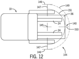
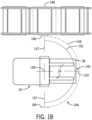
- the image 140 can include one or more reference marks 144 specific to the vehicle's geometry and can be configured to assist the operator 30 in positioning the MHV 10 in a predefined location.
- the overlaid image 140 can include a pivot point 145 illustrated by two perpendicularly intersecting lines.
- the pivot point 145 is defined as the point around which the MHV 10 pivots when the steering angle is set to a maximum steering angle.
- the pivot point 145 can assist the operator in positioning the forks 24 of the MHV 10 at a center region of the intended pallet 36 at the distance the reference mark 144 measures out.
- the one or more reference marks 144 further include two laterally-extending lines 147 that extend outwardly along a line that intersects the pivot point 145.
- the lines 147 begin at a point that is laterally outwardly from the forks 24 and extend outwardly past an outermost edge or side of the MHV 10 a distance that defines an outer radius 149.
- Boundary lines 146 intersect each of the lines 147 at an outermost point on each of the lines 147 and extend in a direction perpendicular to the lines 147 (e.g., in a direction parallel to the forks 24 or the sides of the MHV 10).
- the outer radius 149 generally corresponds with the radius swept by outermost points of a load or pallet on the forks 24 when the MHV pivots along the maximum steering angle.
- the outer radius 149 extends between the intersection points of the lines 147 and the boundary lines 146.
- the reference marks 144 further include an inner radius 151, a forward-facing line 153.
- the inner radius 151 corresponds with the radius swept by the outermost points of the forks 24 when the MHV pivots along the maximum steering angle.
- the forward-facing line 153 extends outwardly in a direction parallel to the forks 24 and extends in a direction that intersects with the pivot point 145.
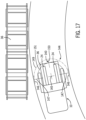
- the image 140 overlaid on the display 74 of the training reinforcement assistance device 38 can help the operator 30 train and perform a right-angle pickup of a load or pallet 36.
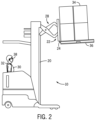
- the operator 30 can instruct the MHV 10 to approach a racking structure 37 that includes the pallet 36.
- the operator 30 can position the MHV 10 so that the reference marks 144 position the MHV 10 to engage and pick the pallet 36.
- the operator 30 can reference the outer radius 149 to assess the clearance needed when turning the MHV 10.
- the operator 30 can also position the MHV 10 so that at least one of the lines 147 (i.e., the line extending from the side of the MHV 10 that is adjacent to the racking structure 37) align with the center of the pallet 36 (e.g., the line 147 may align, or be parallel to, the center stringer on the pallet 36).
- the image 140 can aid the operator 30 in aligning the pivot point 145 with the center of the pallet 36.
- the operator 30 can then turn the steering wheel to the maximum steer angle and pivot the MHV 10 until the forward-facing line 153 aligns with the center stringer of the pallet 36.
- the operator 30 can then straighten out the steering and pick up the pallet 36. After picking up the pallet 36, the operator 30 can reference the outer radius 149 to estimate the clearance needed when turning the MHV 10.
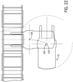
- the overlaid image 140 can be used in much the same way during pallet 36 put away on the racking structure 37.
- the operator 30 can align the reference marks 144 provided within the overlaid image 140 with the center of the intended drop location 148 instead of a center stringer of the pallet 36.
- the operator 30 can reference the outer radius 149 to assess the clearance needed when turning the MHV 10.
- the operator 30 can also position the MHV 10 so that at least one of the lines 147 (i.e., the line extending from the side of the MHV 10 that is adjacent to the racking structure 37) align with the center of intended drop location 148.
- the image 140 can aid the operator 30 in aligning the pivot point 145 with the center of the intended drop location 148.
- the operator 30 can then turn the steering wheel to the maximum steer angle and pivot the MHV 10 until the forward-facing line 153 aligns with the center of the intended drop location 148.
- the operator 30 can then straighten out the steering and drop off the pallet 36 on the racking structure 37 in the intended drop location 148.
- the operator 30 can reference the outer radius 149 to estimate the clearance needed when turning the MHV 10.
- the overlaid image 140 provided by the display 74 may include path projections that align with a floor to indicate the expected path of the MHV's offset envelope to help the operator position the MHV 10 as they approach a target pallet 36 or a racking structure 37 from a distance.
- the projected path can include a first path line 155 and a second path line 157.
- the first path line 155 and the second path line 157 may be included in the overlaid image 140 in addition to the locus lines 130 described herein.
- the first path line 155 and the second path line 157 may be included in the overlaid image 140 in place of the pair of outer lines 130b, or may take the form of the outer lines 130b.
- first path line 155 and the second path line 157 are spaced from the sides of the MHV 10 a distance that corresponds with the different between the inner radius 151 and the outer radius 149 (i.e., the first path line 155 and the second path line 157 generally align with and extend through the lines 147 of the reference marks 144).
- the training reinforcement assistance device 38 can be provided with or inherently know the performance and geometric properties of the MHV 10.
- the training reinforcement assistance device 38 can adapt the overlaid image 140 to adjust the reference marks 144 to account for variations in MHV geometry and MHV type.
- the pivot point 145 can be proximate to the center of the drive wheel axis and the overlaid image 140 can be adapted to account for the vehicle kinematics based on position of the pivot point 145, and the inner radius 151 and the outer radius 149 are adapted accordingly.
- the overlaid image 140 may include an indicator 150, such as a line parallel to the primary direction, of travel of the MHV 10 to be aligned with one or more rack uprights 39 on the racking structure 37.
- the overlaid image 140 may also highlight a predefined or intended position of an object to be manipulated by the MHV 10 that can be represented in real space.
- the overlaid image 140 may provide an outline 152 showing the pallet 36 position ready to be handled. In the illustrated example, the outline 152 is defined around a periphery of the pallet 36.
- the MHV 10 can also communicate the vehicle type and geometry to the training reinforcement assistance device 38 so that the overlaid image 140 can be accurately located for that specific MHV 10 (e.g., based on the pivot point 145 and the associated reference marks 144).
- the outline 152 can serve to communicate to the operator which pallet is being targeted for automated, semi-automated, or assisted handling.
- the outline 152 can represent an outline that is placed in a fixed location relative to the frame of the vehicle (e.g., offset in the forks-first and lateral direction) so that by aligning the intended pallet with this outline 152, the onboard or off-board vehicle control systems such as cameras and/or machine learning computers can narrow their search area for identifying the dimensional position of a pallet to be handled.
- the onboard or off-board vehicle control systems can be continuously searching and identifying patterns that fit its criteria of what constitutes a load to be handled.
- the onboard or off-board vehicle control systems with machine learning can communicate the positions of loads it has identified so they can be visualized through the training reinforcement assistance device 38.
- a camera for example camera 62, can be used to identify loads, and has a known location and orientation on the vehicle and therefore the outline 152 of the identified load can be represented relative to the MHV 10. This position can be communicated to the training reinforcement assistance device 38, which can visualize the outline 152 in that same position relative to the MHV 10 by localizing itself using the fiducials 78. The operator may then select the intended load to be handled simply by looking at it.
- Eye tracking from the training reinforcement assistance device 38 coupled with the orientation of the training reinforcement assistance device 38 can be communicated to the vehicle control systems with machine learning as a vector or pair of vectors (e.g., one for each eye). The intersection of this vector or vectors with the three-dimensional position of identified loads' outlines can then be used to select the load to be handled.
- the onboard or off-board vehicle control system can plan a path to interface with the load that is capable of being executed by the vehicle's particular geometry.
- a motion control algorithm can manipulate the vehicle's steer angle as the operator drives the vehicle in a way to follow the set path.
- the overlaid image 140 may include any combination of the locus lines 130, the reference marks 144, the indicator 150, and/or the outline 152.
- the training reinforcement assistance device 38 may adaptively change the contents of the overlaid image 140 depending on the task being performed by the MHV 10 or the training exercise.
- a maneuver of the MHV 10 can be performed through two actions, which may be accomplished autonomously, semi-autonomously, and/or by the operator 30. In any fashion, the operator 30 can remain in control of the MHV 10 during performance of any actions.
- An automated steering algorithm can interface with a drop location or pallet 148 located a set distance in front of, and to the side of the MHV 10, rotated 90 degrees.
- the onboard or off-board vehicle control system can characterize the dimensional position of the load and has the intelligence to perform the path planning tailored to the position of that load relative to the vehicle.
- the automated steering algorithm can maneuver the MHV 10 in an arc to position the center of its load wheel axis (pivot point) a distance equal to the radius defined by the distance from the pivot point to the corner of a defined standard load plus margin (i.e., the outer radius). From this point, the MHV 10 can turn to its maximum steer angle and pivot about this pivot point until it is facing 90 degrees from its original orientation. At this point, the automated steering algorithm can straighten out the steering wheel so the operator 30 is aligned to drive straight toward the rack.
Landscapes
- Engineering & Computer Science (AREA)
- Physics & Mathematics (AREA)
- Structural Engineering (AREA)
- Transportation (AREA)
- Theoretical Computer Science (AREA)
- General Physics & Mathematics (AREA)
- Remote Sensing (AREA)
- Radar, Positioning & Navigation (AREA)
- General Engineering & Computer Science (AREA)
- Aviation & Aerospace Engineering (AREA)
- Civil Engineering (AREA)
- Life Sciences & Earth Sciences (AREA)
- Geology (AREA)
- Mechanical Engineering (AREA)
- Automation & Control Theory (AREA)
- Human Computer Interaction (AREA)
- Educational Administration (AREA)
- Educational Technology (AREA)
- Business, Economics & Management (AREA)
- Electromagnetism (AREA)
- Combustion & Propulsion (AREA)
- Chemical & Material Sciences (AREA)
- Forklifts And Lifting Vehicles (AREA)
- User Interface Of Digital Computer (AREA)
- Rehabilitation Tools (AREA)
- Motorcycle And Bicycle Frame (AREA)
- Management, Administration, Business Operations System, And Electronic Commerce (AREA)
- Acyclic And Carbocyclic Compounds In Medicinal Compositions (AREA)
Claims (12)
- System, umfassend:eine Trainingsverstärkungs-Assistenzvorrichtung (38) mit einem Rahmen (40), der ein optisches System (46) trägt, wobei das optische System (46) konfiguriert ist, um virtuelle Inhalte auf einer Anzeige (74) anzuzeigen und um das Betrachten von mindestens einem Abschnitt einer Umgebung zu ermöglichen;einen Bildgeber (72), der funktionsfähig mit dem Rahmen (40) gekoppelt und konfiguriert ist, um ein Bild von einer Umgebung des Bildgebers (72) zu erzeugen;einen Beschleunigungsmesser (70), der funktionsfähig mit dem Rahmen gekoppelt und konfiguriert ist, um eine Ausrichtung des Rahmens zu erfassen;ein Augenverfolgungssystem (42), das funktionsfähig mit dem Rahmen (40) gekoppelt und konfiguriert ist, um eine Blickrichtung eines Bedieners zu erfassen; undeine Steuerung (50), die funktionsfähig mit dem Bildgeber (72) und der Anzeige (74) gekoppelt ist,wobei die Steuerung (50) konfiguriert ist, um Umgebungsinformationen von mindestens einem von dem Bildgeber (72), dem Beschleunigungsmesser (70) oder dem Augenverfolgungssystem zu empfangen und das Bild (140) der Umgebung zu überlagern, um einen Bediener (30) beim Manövrieren eines Materialhandhabungsfahrzeugs (10) basierend auf der Fahrzeugkinematik des Materialhandhabungsfahrzeugs (10) innerhalb einer Sichtlinie des Bedieners (30) durch das optische System (46) zu unterstützen, und wobei das Bild (140) auf mindestens einer Gabel (24) des Materialhandhabungsfahrzeugs (10) positioniert ist, wie es durch das optische System (46) wahrgenommen wird,vorzugsweise umfasst das System das Materialhandhabungsfahrzeug (10).
- System nach Anspruch 1, ferner umfassend:einen Sendeempfänger (52), der funktionsfähig mit der Steuerung (50) gekoppelt ist;wobei der Sendeempfänger (52) konfiguriert ist, um mit einem Materialhandhabungsfahrzeug-Sendeempfänger (80) zu kommunizieren, wenn diese miteinander gekoppelt sind, wobei der Materialhandhabungsfahrzeug-Sendeempfänger (80) ferner mit einer Steuereinheit (82) des Materialhandhabungsfahrzeugs (10) gekoppelt ist.
- System nach Anspruch 1 oder 2, wobei das Bild (140) eine oder mehrere Referenzmarken (144) einschließt, die spezifisch für die Geometrie eines Materialhandhabungsfahrzeugs sind und konfiguriert sind, um den Bediener (30) beim Positionieren des Materialhandhabungsfahrzeugs (10) an einem vordefinierten Standort zu unterstützen.
- System nach Anspruch 3, wobei die eine oder die mehreren Referenzmarken (144) einen Drehpunkt (145) einschließen, der durch das Materialhandhabungsfahrzeug (10) definiert ist.
- System nach Anspruch 4, wobei der Drehpunkt an einem Punkt definiert ist, um den das Materialhandhabungsfahrzeug (10) schwenkt, wenn ein Lenkwinkel auf einen maximalen Lenkwinkel eingestellt ist.
- System nach einem der Ansprüche 3 bis 5, wobei die eine oder die mehreren Referenzmarken (144) einen Innenradius (151) einschließen, der einem Radius entspricht, der von den äußersten Punkten mindestens einer Gabel (24) am Materialhandhabungsfahrzeug (10) überstrichen wird, wenn das Materialhandhabungsfahrzeug (10) um einen maximalen Lenkwinkel schwenkt.
- System nach einem der Ansprüche 3 bis 6, wobei die eine oder die mehreren Referenzmarken (144) einen Außenradius (149) einschließen, der einem Radius entspricht, der von den äußersten Punkten einer Lastposition auf mindestens einer Gabel (24) des Materialhandhabungsfahrzeugs (10) überstrichen wird, wenn das Materialhandhabungsfahrzeug um einen maximalen Lenkwinkel schwenkt.
- System nach einem der vorstehenden Ansprüche, wobei die Fahrzeugkinematik mindestens eines von einer Höhe der mindestens einen Gabel (24) relativ zu einer Basis des Materialhandhabungsfahrzeugs (10), einer Neigung der mindestens einen Gabel (24) relativ zu der Basis, einer Seitenverschiebungsposition der mindestens einen Gabel (24) relativ zu der Basis, einer Reichweite der mindestens einen Gabel (24) relativ zu der Basis, einem Lenkwinkel des Materialhandhabungsfahrzeugs (10), einem Radstand des Materialhandhabungsfahrzeugs (10) oder
einer Gesamtbreite des Materialhandhabungsfahrzeugs (10) einschließt. - System nach einem der vorstehenden Ansprüche, wobei der Bildgeber (72) konfiguriert ist, um eine oder mehrere Passermarken (78) zu erfassen, um den Rahmen der Trainingsverstärkungs-Assistenzvorrichtung relativ zu dem Materialhandhabungsfahrzeug (10) auszurichten und zu lokalisieren.
- System nach Anspruch 9, wobei die Passermarken (78) an einer Fahrzeugoberfläche des Materialhandhabungsfahrzeugs (10) auf Oberflächen angebracht sind, die von einer Fahrerkabine (16) aus sichtbar sind.
- System nach einem der Ansprüche 8 bis 10, wobei die Passermarken (78) eine erste Passermarke und eine zweite Passermarke einschließen, wobei sich die erste Passermarke innerhalb eines Sichtfelds des Bildgebers (72) befindet, wenn der Bediener (30) in einer ersten Richtung ausgerichtet ist, und sich die zweite Passermarke innerhalb des Sichtfelds befindet, wenn der Bediener (30) in einer zweiten, entgegengesetzten Richtung ausgerichtet ist.
- System nach einem der vorstehenden Ansprüche, wobei das Bild eine Pfadprojektion des Materialhandhabungsfahrzeugs (10) basierend auf einem aktuellen Lenkwinkel und einer Geschwindigkeit des Materialhandhabungsfahrzeugs (10) einschließt.
Priority Applications (1)
| Application Number | Priority Date | Filing Date | Title |
|---|---|---|---|
| EP24187323.1A EP4517719A3 (de) | 2021-03-04 | 2022-03-04 | Assistenzsysteme und verfahren für ein materialhandhabungsfahrzeug |
Applications Claiming Priority (1)
| Application Number | Priority Date | Filing Date | Title |
|---|---|---|---|
| US202163156505P | 2021-03-04 | 2021-03-04 |
Related Child Applications (1)
| Application Number | Title | Priority Date | Filing Date |
|---|---|---|---|
| EP24187323.1A Division EP4517719A3 (de) | 2021-03-04 | 2022-03-04 | Assistenzsysteme und verfahren für ein materialhandhabungsfahrzeug |
Publications (3)
| Publication Number | Publication Date |
|---|---|
| EP4053071A1 EP4053071A1 (de) | 2022-09-07 |
| EP4053071B1 true EP4053071B1 (de) | 2024-07-10 |
| EP4053071C0 EP4053071C0 (de) | 2024-07-10 |
Family
ID=81326232
Family Applications (2)
| Application Number | Title | Priority Date | Filing Date |
|---|---|---|---|
| EP22160158.6A Active EP4053071B1 (de) | 2021-03-04 | 2022-03-04 | Assistenzsysteme und -verfahren für ein materialhandhabungsfahrzeug |
| EP24187323.1A Pending EP4517719A3 (de) | 2021-03-04 | 2022-03-04 | Assistenzsysteme und verfahren für ein materialhandhabungsfahrzeug |
Family Applications After (1)
| Application Number | Title | Priority Date | Filing Date |
|---|---|---|---|
| EP24187323.1A Pending EP4517719A3 (de) | 2021-03-04 | 2022-03-04 | Assistenzsysteme und verfahren für ein materialhandhabungsfahrzeug |
Country Status (6)
| Country | Link |
|---|---|
| US (1) | US20220281728A1 (de) |
| EP (2) | EP4053071B1 (de) |
| CN (1) | CN115016634A (de) |
| AU (1) | AU2022201469A1 (de) |
| CA (1) | CA3151285A1 (de) |
| MX (1) | MX2022002668A (de) |
Families Citing this family (6)
| Publication number | Priority date | Publication date | Assignee | Title |
|---|---|---|---|---|
| US20230251662A1 (en) * | 2022-02-04 | 2023-08-10 | Ford Global Technologies, Llc | Systems and methods for assisting human-driven vehicles of a manufacturing environment |
| US20230303373A1 (en) * | 2022-03-25 | 2023-09-28 | Logistics and Supply Chain MultiTech R&D Centre Limited | Teleoperated material handling system and material handling vehicle |
| AU2023251429A1 (en) * | 2022-10-20 | 2024-05-09 | The Raymond Corporation | Operation assistance for autonomous material handling vehicles |
| JP7720826B2 (ja) * | 2022-12-22 | 2025-08-08 | 三菱ロジスネクスト株式会社 | 表示装置、視界補助システム、産業車両、制御方法及びプログラム |
| JP7615114B2 (ja) * | 2022-12-22 | 2025-01-16 | 三菱ロジスネクスト株式会社 | 表示装置、荷下ろし補助システム、産業車両、制御方法及びプログラム |
| CN119430027A (zh) * | 2024-11-12 | 2025-02-14 | 广东电网有限责任公司 | 拆卸辅助装置 |
Family Cites Families (17)
| Publication number | Priority date | Publication date | Assignee | Title |
|---|---|---|---|---|
| DE102007063226A1 (de) * | 2007-12-31 | 2009-07-02 | Still Gmbh | Verfahren zur Fahrunterstützung bei einem Flurförderzeug sowie Flurförderzeug |
| EP2933707B1 (de) * | 2014-04-14 | 2017-12-06 | iOnRoad Technologies Ltd. | Darstellungseinstellung für kopfmontierte Anzeige |
| US11461936B2 (en) * | 2015-03-17 | 2022-10-04 | Raytrx, Llc | Wearable image manipulation and control system with micro-displays and augmentation of vision and sensing in augmented reality glasses |
| EP3408210B1 (de) * | 2016-04-08 | 2021-10-20 | Liebherr-Components Biberach GmbH | Fernsteuer-einrichtung für kran, baumaschine und/oder flurförderzeug |
| WO2017155488A1 (en) * | 2016-03-11 | 2017-09-14 | Still Arser Is Makinalari Servis Ve Ticaret Anonim Sirketi | A forklift training simulator system |
| US11087639B2 (en) * | 2016-04-04 | 2021-08-10 | The Raymond Corporation | Systems and methods for vehicle simulation |
| WO2019084163A1 (en) * | 2017-10-25 | 2019-05-02 | Oshkosh Corporation | VEHICLE CONTROL SYSTEM |
| EP3729243A4 (de) * | 2017-12-19 | 2021-09-15 | Datalogic IP Tech S.r.l. | Am körper eines benutzers tragbare systeme und verfahren zum sammeln von daten und zur bereitstellung von informationen |
| JP7119795B2 (ja) * | 2018-09-06 | 2022-08-17 | 株式会社豊田自動織機 | フォークリフト用遠隔操作システム |
| DE102018130779A1 (de) * | 2018-12-04 | 2020-06-04 | Still Gmbh | Verfahren zum Betreiben eines autonomen Flurförderzeugs und intralogistisches System mit einem autonomen Flurförderzeug |
| US12474813B2 (en) * | 2019-01-31 | 2025-11-18 | Rypplzz, Inc. | Systems and methods for augmented reality with precise tracking |
| DE102019112954A1 (de) * | 2019-05-16 | 2020-11-19 | Jungheinrich Aktiengesellschaft | Verfahren zur Lagerungsunterstützung bei einem Flurförderzeug und Flurförderzeug |
| US11615707B2 (en) * | 2019-05-29 | 2023-03-28 | Deere & Company | Guidance display system for work vehicles and work implements |
| WO2021006362A1 (ko) * | 2019-07-05 | 2021-01-14 | 엘지전자 주식회사 | 운전자 시선 감지를 통한 차량의 주행 상황 표시 방법 및 이를 위한 장치 |
| JP7689308B2 (ja) * | 2020-02-07 | 2025-06-06 | パナソニックIpマネジメント株式会社 | 測位システム |
| US20220267131A1 (en) * | 2021-02-23 | 2022-08-25 | Phantom Auto Inc. | Smart warehouse safety mechanisms |
| US11663739B2 (en) * | 2021-03-11 | 2023-05-30 | Microsoft Technology Licensing, Llc | Fiducial marker based field calibration of a device |
-
2022
- 2022-03-03 MX MX2022002668A patent/MX2022002668A/es unknown
- 2022-03-03 AU AU2022201469A patent/AU2022201469A1/en active Pending
- 2022-03-03 US US17/685,715 patent/US20220281728A1/en active Pending
- 2022-03-04 EP EP22160158.6A patent/EP4053071B1/de active Active
- 2022-03-04 CA CA3151285A patent/CA3151285A1/en active Pending
- 2022-03-04 CN CN202210211586.0A patent/CN115016634A/zh active Pending
- 2022-03-04 EP EP24187323.1A patent/EP4517719A3/de active Pending
Also Published As
| Publication number | Publication date |
|---|---|
| AU2022201469A1 (en) | 2022-09-22 |
| CA3151285A1 (en) | 2022-09-04 |
| EP4053071A1 (de) | 2022-09-07 |
| MX2022002668A (es) | 2022-09-05 |
| CN115016634A (zh) | 2022-09-06 |
| EP4053071C0 (de) | 2024-07-10 |
| EP4517719A3 (de) | 2025-03-26 |
| US20220281728A1 (en) | 2022-09-08 |
| EP4517719A2 (de) | 2025-03-05 |
Similar Documents
| Publication | Publication Date | Title |
|---|---|---|
| EP4053071B1 (de) | Assistenzsysteme und -verfahren für ein materialhandhabungsfahrzeug | |
| US11312570B2 (en) | Method and apparatus for visual support of commission acts | |
| CN113632117A (zh) | 仓库管理方法和系统 | |
| US20190137991A1 (en) | Method and system to retrofit industrial lift trucks for automated material handling in supply chain and logistics operations | |
| Kelly et al. | Field and service applications-an infrastructure-free automated guided vehicle based on computer vision-an effort to make an industrial robot vehicle that can operate without supporting infrastructure | |
| CN110945449B (zh) | 现场环境的实时监督式机器学习系统与方法 | |
| KR102859547B1 (ko) | 로봇 시스템 및 그 제어 방법 | |
| Kalinov et al. | Warevr: Virtual reality interface for supervision of autonomous robotic system aimed at warehouse stocktaking | |
| EP2677274B1 (de) | System und Verfahren zur Führung einer mobilen Vorrichtung | |
| JP7017294B2 (ja) | 有人無人フォークリフトおよび荷役システム | |
| CN111017804A (zh) | 一种智能移动转运系统及其转运方法 | |
| US20240017976A1 (en) | Advanced material handling vehicle | |
| US20250109002A1 (en) | Method and system for operating automated forklift | |
| JP7119795B2 (ja) | フォークリフト用遠隔操作システム | |
| US20210247493A1 (en) | Non-destructive kit mounting system for driverless industrial vehicles | |
| US20230303373A1 (en) | Teleoperated material handling system and material handling vehicle | |
| KR20220152564A (ko) | 모듈형 바퀴 장치 | |
| KR20230109807A (ko) | 차량 및 차량의 제어방법 | |
| JP2021076995A (ja) | 荷役システム | |
| HK40077448A (en) | Assistance systems and methods for a material handling vehicle | |
| US20250348084A1 (en) | System and method for generating complex runtime path networks from incomplete demonstration of trained activities | |
| JP2021066539A (ja) | 荷役車両の荷役作業支援装置 | |
| JP2024090081A (ja) | 視界補助システム、産業車両、視界補助方法及びプログラム | |
| KR20230120026A (ko) | 물류창고 관리 방법 및 시스템 | |
| TWI689743B (zh) | 物件定位系統 |
Legal Events
| Date | Code | Title | Description |
|---|---|---|---|
| PUAI | Public reference made under article 153(3) epc to a published international application that has entered the european phase |
Free format text: ORIGINAL CODE: 0009012 |
|
| STAA | Information on the status of an ep patent application or granted ep patent |
Free format text: STATUS: THE APPLICATION HAS BEEN PUBLISHED |
|
| AK | Designated contracting states |
Kind code of ref document: A1 Designated state(s): AL AT BE BG CH CY CZ DE DK EE ES FI FR GB GR HR HU IE IS IT LI LT LU LV MC MK MT NL NO PL PT RO RS SE SI SK SM TR |
|
| STAA | Information on the status of an ep patent application or granted ep patent |
Free format text: STATUS: REQUEST FOR EXAMINATION WAS MADE |
|
| 17P | Request for examination filed |
Effective date: 20230307 |
|
| RBV | Designated contracting states (corrected) |
Designated state(s): AL AT BE BG CH CY CZ DE DK EE ES FI FR GB GR HR HU IE IS IT LI LT LU LV MC MK MT NL NO PL PT RO RS SE SI SK SM TR |
|
| GRAP | Despatch of communication of intention to grant a patent |
Free format text: ORIGINAL CODE: EPIDOSNIGR1 |
|
| STAA | Information on the status of an ep patent application or granted ep patent |
Free format text: STATUS: GRANT OF PATENT IS INTENDED |
|
| INTG | Intention to grant announced |
Effective date: 20230926 |
|
| GRAJ | Information related to disapproval of communication of intention to grant by the applicant or resumption of examination proceedings by the epo deleted |
Free format text: ORIGINAL CODE: EPIDOSDIGR1 |
|
| STAA | Information on the status of an ep patent application or granted ep patent |
Free format text: STATUS: REQUEST FOR EXAMINATION WAS MADE |
|
| GRAP | Despatch of communication of intention to grant a patent |
Free format text: ORIGINAL CODE: EPIDOSNIGR1 |
|
| STAA | Information on the status of an ep patent application or granted ep patent |
Free format text: STATUS: GRANT OF PATENT IS INTENDED |
|
| INTC | Intention to grant announced (deleted) | ||
| INTG | Intention to grant announced |
Effective date: 20240205 |
|
| GRAS | Grant fee paid |
Free format text: ORIGINAL CODE: EPIDOSNIGR3 |
|
| GRAA | (expected) grant |
Free format text: ORIGINAL CODE: 0009210 |
|
| STAA | Information on the status of an ep patent application or granted ep patent |
Free format text: STATUS: THE PATENT HAS BEEN GRANTED |
|
| AK | Designated contracting states |
Kind code of ref document: B1 Designated state(s): AL AT BE BG CH CY CZ DE DK EE ES FI FR GB GR HR HU IE IS IT LI LT LU LV MC MK MT NL NO PL PT RO RS SE SI SK SM TR |
|
| REG | Reference to a national code |
Ref country code: CH Ref legal event code: EP |
|
| REG | Reference to a national code |
Ref country code: DE Ref legal event code: R096 Ref document number: 602022004394 Country of ref document: DE |
|
| U01 | Request for unitary effect filed |
Effective date: 20240805 |
|
| U07 | Unitary effect registered |
Designated state(s): AT BE BG DE DK EE FI FR IT LT LU LV MT NL PT SE SI Effective date: 20240820 |
|
| PG25 | Lapsed in a contracting state [announced via postgrant information from national office to epo] |
Ref country code: NO Free format text: LAPSE BECAUSE OF FAILURE TO SUBMIT A TRANSLATION OF THE DESCRIPTION OR TO PAY THE FEE WITHIN THE PRESCRIBED TIME-LIMIT Effective date: 20241010 |
|
| PG25 | Lapsed in a contracting state [announced via postgrant information from national office to epo] |
Ref country code: GR Free format text: LAPSE BECAUSE OF FAILURE TO SUBMIT A TRANSLATION OF THE DESCRIPTION OR TO PAY THE FEE WITHIN THE PRESCRIBED TIME-LIMIT Effective date: 20241011 Ref country code: PL Free format text: LAPSE BECAUSE OF FAILURE TO SUBMIT A TRANSLATION OF THE DESCRIPTION OR TO PAY THE FEE WITHIN THE PRESCRIBED TIME-LIMIT Effective date: 20240710 |
|
| PG25 | Lapsed in a contracting state [announced via postgrant information from national office to epo] |
Ref country code: IS Free format text: LAPSE BECAUSE OF FAILURE TO SUBMIT A TRANSLATION OF THE DESCRIPTION OR TO PAY THE FEE WITHIN THE PRESCRIBED TIME-LIMIT Effective date: 20241110 |
|
| PG25 | Lapsed in a contracting state [announced via postgrant information from national office to epo] |
Ref country code: HR Free format text: LAPSE BECAUSE OF FAILURE TO SUBMIT A TRANSLATION OF THE DESCRIPTION OR TO PAY THE FEE WITHIN THE PRESCRIBED TIME-LIMIT Effective date: 20240710 |
|
| PG25 | Lapsed in a contracting state [announced via postgrant information from national office to epo] |
Ref country code: ES Free format text: LAPSE BECAUSE OF FAILURE TO SUBMIT A TRANSLATION OF THE DESCRIPTION OR TO PAY THE FEE WITHIN THE PRESCRIBED TIME-LIMIT Effective date: 20240710 Ref country code: RS Free format text: LAPSE BECAUSE OF FAILURE TO SUBMIT A TRANSLATION OF THE DESCRIPTION OR TO PAY THE FEE WITHIN THE PRESCRIBED TIME-LIMIT Effective date: 20241010 |
|
| PG25 | Lapsed in a contracting state [announced via postgrant information from national office to epo] |
Ref country code: RS Free format text: LAPSE BECAUSE OF FAILURE TO SUBMIT A TRANSLATION OF THE DESCRIPTION OR TO PAY THE FEE WITHIN THE PRESCRIBED TIME-LIMIT Effective date: 20241010 Ref country code: PL Free format text: LAPSE BECAUSE OF FAILURE TO SUBMIT A TRANSLATION OF THE DESCRIPTION OR TO PAY THE FEE WITHIN THE PRESCRIBED TIME-LIMIT Effective date: 20240710 Ref country code: NO Free format text: LAPSE BECAUSE OF FAILURE TO SUBMIT A TRANSLATION OF THE DESCRIPTION OR TO PAY THE FEE WITHIN THE PRESCRIBED TIME-LIMIT Effective date: 20241010 Ref country code: IS Free format text: LAPSE BECAUSE OF FAILURE TO SUBMIT A TRANSLATION OF THE DESCRIPTION OR TO PAY THE FEE WITHIN THE PRESCRIBED TIME-LIMIT Effective date: 20241110 Ref country code: HR Free format text: LAPSE BECAUSE OF FAILURE TO SUBMIT A TRANSLATION OF THE DESCRIPTION OR TO PAY THE FEE WITHIN THE PRESCRIBED TIME-LIMIT Effective date: 20240710 Ref country code: GR Free format text: LAPSE BECAUSE OF FAILURE TO SUBMIT A TRANSLATION OF THE DESCRIPTION OR TO PAY THE FEE WITHIN THE PRESCRIBED TIME-LIMIT Effective date: 20241011 Ref country code: ES Free format text: LAPSE BECAUSE OF FAILURE TO SUBMIT A TRANSLATION OF THE DESCRIPTION OR TO PAY THE FEE WITHIN THE PRESCRIBED TIME-LIMIT Effective date: 20240710 |
|
| U20 | Renewal fee for the european patent with unitary effect paid |
Year of fee payment: 4 Effective date: 20250123 |
|
| PG25 | Lapsed in a contracting state [announced via postgrant information from national office to epo] |
Ref country code: SM Free format text: LAPSE BECAUSE OF FAILURE TO SUBMIT A TRANSLATION OF THE DESCRIPTION OR TO PAY THE FEE WITHIN THE PRESCRIBED TIME-LIMIT Effective date: 20240710 |
|
| PG25 | Lapsed in a contracting state [announced via postgrant information from national office to epo] |
Ref country code: CZ Free format text: LAPSE BECAUSE OF FAILURE TO SUBMIT A TRANSLATION OF THE DESCRIPTION OR TO PAY THE FEE WITHIN THE PRESCRIBED TIME-LIMIT Effective date: 20240710 |
|
| PG25 | Lapsed in a contracting state [announced via postgrant information from national office to epo] |
Ref country code: SK Free format text: LAPSE BECAUSE OF FAILURE TO SUBMIT A TRANSLATION OF THE DESCRIPTION OR TO PAY THE FEE WITHIN THE PRESCRIBED TIME-LIMIT Effective date: 20240710 |
|
| PLBE | No opposition filed within time limit |
Free format text: ORIGINAL CODE: 0009261 |
|
| STAA | Information on the status of an ep patent application or granted ep patent |
Free format text: STATUS: NO OPPOSITION FILED WITHIN TIME LIMIT |
|
| 26N | No opposition filed |
Effective date: 20250411 |
|
| PG25 | Lapsed in a contracting state [announced via postgrant information from national office to epo] |
Ref country code: MC Free format text: LAPSE BECAUSE OF FAILURE TO SUBMIT A TRANSLATION OF THE DESCRIPTION OR TO PAY THE FEE WITHIN THE PRESCRIBED TIME-LIMIT Effective date: 20240710 |
|
| REG | Reference to a national code |
Ref country code: CH Ref legal event code: H13 Free format text: ST27 STATUS EVENT CODE: U-0-0-H10-H13 (AS PROVIDED BY THE NATIONAL OFFICE) Effective date: 20251024 |