EP4053035B1 - A tethered closure system - Google Patents
A tethered closure system Download PDFInfo
- Publication number
- EP4053035B1 EP4053035B1 EP21382177.0A EP21382177A EP4053035B1 EP 4053035 B1 EP4053035 B1 EP 4053035B1 EP 21382177 A EP21382177 A EP 21382177A EP 4053035 B1 EP4053035 B1 EP 4053035B1
- Authority
- EP
- European Patent Office
- Prior art keywords
- closure
- neck portion
- tether
- lead
- container
- Prior art date
- Legal status (The legal status is an assumption and is not a legal conclusion. Google has not performed a legal analysis and makes no representation as to the accuracy of the status listed.)
- Active
Links
- 230000015572 biosynthetic process Effects 0.000 claims description 29
- 238000005755 formation reaction Methods 0.000 claims description 29
- 230000013011 mating Effects 0.000 claims description 9
- 230000000007 visual effect Effects 0.000 claims description 9
- 230000008878 coupling Effects 0.000 description 9
- 238000010168 coupling process Methods 0.000 description 9
- 238000005859 coupling reaction Methods 0.000 description 9
- 239000000463 material Substances 0.000 description 5
- 239000000243 solution Substances 0.000 description 5
- 230000008901 benefit Effects 0.000 description 4
- 239000004033 plastic Substances 0.000 description 3
- 229920003023 plastic Polymers 0.000 description 3
- -1 polyethylene Polymers 0.000 description 3
- 239000004698 Polyethylene Substances 0.000 description 2
- 239000004743 Polypropylene Substances 0.000 description 2
- 230000000694 effects Effects 0.000 description 2
- 229920001903 high density polyethylene Polymers 0.000 description 2
- 239000004700 high-density polyethylene Substances 0.000 description 2
- 230000014759 maintenance of location Effects 0.000 description 2
- 238000004519 manufacturing process Methods 0.000 description 2
- 229920000573 polyethylene Polymers 0.000 description 2
- 239000005020 polyethylene terephthalate Substances 0.000 description 2
- 229920000139 polyethylene terephthalate Polymers 0.000 description 2
- 229920001155 polypropylene Polymers 0.000 description 2
- 230000000717 retained effect Effects 0.000 description 2
- 230000003068 static effect Effects 0.000 description 2
- 238000004873 anchoring Methods 0.000 description 1
- 230000000903 blocking effect Effects 0.000 description 1
- 238000000748 compression moulding Methods 0.000 description 1
- 238000009826 distribution Methods 0.000 description 1
- 230000035622 drinking Effects 0.000 description 1
- 230000007613 environmental effect Effects 0.000 description 1
- 230000006870 function Effects 0.000 description 1
- 238000001746 injection moulding Methods 0.000 description 1
- 230000002452 interceptive effect Effects 0.000 description 1
- 239000012263 liquid product Substances 0.000 description 1
- 230000003446 memory effect Effects 0.000 description 1
- 238000000034 method Methods 0.000 description 1
- 239000000203 mixture Substances 0.000 description 1
- 229920000098 polyolefin Polymers 0.000 description 1
- 238000004064 recycling Methods 0.000 description 1
- 238000004513 sizing Methods 0.000 description 1
Images


Classifications
-
- B—PERFORMING OPERATIONS; TRANSPORTING
- B65—CONVEYING; PACKING; STORING; HANDLING THIN OR FILAMENTARY MATERIAL
- B65D—CONTAINERS FOR STORAGE OR TRANSPORT OF ARTICLES OR MATERIALS, e.g. BAGS, BARRELS, BOTTLES, BOXES, CANS, CARTONS, CRATES, DRUMS, JARS, TANKS, HOPPERS, FORWARDING CONTAINERS; ACCESSORIES, CLOSURES, OR FITTINGS THEREFOR; PACKAGING ELEMENTS; PACKAGES
- B65D55/00—Accessories for container closures not otherwise provided for
- B65D55/16—Devices preventing loss of removable closure members
-
- B—PERFORMING OPERATIONS; TRANSPORTING
- B65—CONVEYING; PACKING; STORING; HANDLING THIN OR FILAMENTARY MATERIAL
- B65D—CONTAINERS FOR STORAGE OR TRANSPORT OF ARTICLES OR MATERIALS, e.g. BAGS, BARRELS, BOTTLES, BOXES, CANS, CARTONS, CRATES, DRUMS, JARS, TANKS, HOPPERS, FORWARDING CONTAINERS; ACCESSORIES, CLOSURES, OR FITTINGS THEREFOR; PACKAGING ELEMENTS; PACKAGES
- B65D51/00—Closures not otherwise provided for
- B65D51/24—Closures not otherwise provided for combined or co-operating with auxiliary devices for non-closing purposes
- B65D51/242—Closures not otherwise provided for combined or co-operating with auxiliary devices for non-closing purposes provided with means for facilitating lifting or suspending of the container
-
- B—PERFORMING OPERATIONS; TRANSPORTING
- B65—CONVEYING; PACKING; STORING; HANDLING THIN OR FILAMENTARY MATERIAL
- B65D—CONTAINERS FOR STORAGE OR TRANSPORT OF ARTICLES OR MATERIALS, e.g. BAGS, BARRELS, BOTTLES, BOXES, CANS, CARTONS, CRATES, DRUMS, JARS, TANKS, HOPPERS, FORWARDING CONTAINERS; ACCESSORIES, CLOSURES, OR FITTINGS THEREFOR; PACKAGING ELEMENTS; PACKAGES
- B65D1/00—Containers having bodies formed in one piece, e.g. by casting metallic material, by moulding plastics, by blowing vitreous material, by throwing ceramic material, by moulding pulped fibrous material, by deep-drawing operations performed on sheet material
- B65D1/02—Bottles or similar containers with necks or like restricted apertures, designed for pouring contents
- B65D1/0223—Bottles or similar containers with necks or like restricted apertures, designed for pouring contents characterised by shape
- B65D1/023—Neck construction
- B65D1/0246—Closure retaining means, e.g. beads, screw-threads
-
- B—PERFORMING OPERATIONS; TRANSPORTING
- B65—CONVEYING; PACKING; STORING; HANDLING THIN OR FILAMENTARY MATERIAL
- B65D—CONTAINERS FOR STORAGE OR TRANSPORT OF ARTICLES OR MATERIALS, e.g. BAGS, BARRELS, BOTTLES, BOXES, CANS, CARTONS, CRATES, DRUMS, JARS, TANKS, HOPPERS, FORWARDING CONTAINERS; ACCESSORIES, CLOSURES, OR FITTINGS THEREFOR; PACKAGING ELEMENTS; PACKAGES
- B65D41/00—Caps, e.g. crown caps or crown seals, i.e. members having parts arranged for engagement with the external periphery of a neck or wall defining a pouring opening or discharge aperture; Protective cap-like covers for closure members, e.g. decorative covers of metal foil or paper
- B65D41/32—Caps or cap-like covers with lines of weakness, tearing-strips, tags, or like opening or removal devices, e.g. to facilitate formation of pouring openings
- B65D41/34—Threaded or like caps or cap-like covers provided with tamper elements formed in, or attached to, the closure skirt
- B65D41/3442—Threaded or like caps or cap-like covers provided with tamper elements formed in, or attached to, the closure skirt with rigid bead or projections formed on the tamper element and coacting with bead or projections on the container
- B65D41/3447—Threaded or like caps or cap-like covers provided with tamper elements formed in, or attached to, the closure skirt with rigid bead or projections formed on the tamper element and coacting with bead or projections on the container the tamper element being integrally connected to the closure by means of bridges
-
- B—PERFORMING OPERATIONS; TRANSPORTING
- B65—CONVEYING; PACKING; STORING; HANDLING THIN OR FILAMENTARY MATERIAL
- B65D—CONTAINERS FOR STORAGE OR TRANSPORT OF ARTICLES OR MATERIALS, e.g. BAGS, BARRELS, BOTTLES, BOXES, CANS, CARTONS, CRATES, DRUMS, JARS, TANKS, HOPPERS, FORWARDING CONTAINERS; ACCESSORIES, CLOSURES, OR FITTINGS THEREFOR; PACKAGING ELEMENTS; PACKAGES
- B65D2401/00—Tamper-indicating means
- B65D2401/15—Tearable part of the closure
- B65D2401/30—Tamper-ring remaining connected to closure after initial removal
Definitions
- the invention relates to a closing system combining a threaded closure and a matching container threaded neck portion, defining a container opening, to reversibly close the said container opening.
- the closure is of the type having a bottom tamper-evident band originally linked to a closure shell of the closure through frangible connections.
- frangible connections break forming an unattached tether preventing the closure shell and the tamper-evident band to form two separated individual components.
- the patent document US3904062 describes a closure system consisting of a screw closure provided with a tamper-evident band that remains axially retained in a container neck portion when the closure is unscrewed from the said container neck portion.
- the tamper-evident band is originally connected to the main body of the closure along frangible connections that are broken during a first opening operation of the container determining a tether that links the unscrewed main body of the closure to the tamper-evident band, which remains anchored to the container neck portion.
- the rupture of the frangible connections indicates to a user that the contents of the container may have been accessed.
- the tether prevents the unscrewed closure main body and the tamper-evident band, and therefore the container, to form two separated individual components. In other words, it prevents or inhibits the closure shell main body from being separated from the container. This favours the recycling of the container along with the complete closure parts.
- EP3584190 describes a closure system with some common features with that described in the previous reference. More specifically, the closure of EP3584190 comprises a closure shell having an annular skirt portion with first and second frangible connections that partially detachably connect the annular skirt portion with a tamper-evident band. When the frangible connections are broken a tether is exposed with one end attached to the annular skirt portion and with its opposite end attached to the tamper-evident band. In the system of EP3584190 the frangible connections are configured for the tether to extend greater than about 300 degrees around the circumference of the closure.
- EP3584190 by having the unattached portion of the tether extending greater than about 300 degrees, the distance of the closure shell from the container neck portion to which the tamper-evident band is anchored is increased, eliminating or reducing the chances of the closure shell from interfering with a user while drinking or pouring the content of the container.
- a long tether connecting in captive fashion the closure shell of the closure to the tamper-evident band would favor positioning the unscrewed closure shell of the closure moved away from the container opening region without the risk of the said closure shell accidentally reaching across the cross-section of the container opening, for example, when the container is tilted.
- the exposed tether is affected by a memory effect that makes it to naturally adopt a curved shape (due to the original circumferential arch shape that the strip of material, that later will determine the tether, has in the manufactured closure).
- the tether conventionally made of plastic, performs like a sort of a spring slightly biasing the closure shell towards the container opening.
- the patent document CN 208264903 U describes two embodiments of a tethered closure system wherein a tether can be pulled to adopt an exposed state when a cap is reclosed.
- a long tether may be manually folded outwards so as not to surround the bottle mouth to form a lifting ring of the bottle cap, so that a user can conveniently lift the plastic bottle.
- a short tether is pulled outwards, approaching their connecting portions with the cap and the safety ring, and the tether extends in a ring shape outside the bottle cap to form a lifting ring of the bottle cap. In both cases, if the tether is not manually pulled outwards it will surround the bottle mouth located between the cap body and the safety ring without protruding when the bottle is re-closed.
- the patent document CN1631740 which accords with the preamble of claim 1, relates to a safety bottle cap including the cap body and a safety ring linked under the body. It is of interest that there is a flexible permanent tether linking the cap body with the safety ring, this tether being over dimensioned to form a carrying handle, at least for the fingers to insert and pick up.
- This cap has advantages such as providing a safe seal, convenient environmental protection and in this case also easy carrying features.
- the proposed closure system combines a pair of a closure and a container neck portion with mating threaded formations offering multiple angular distributed engagement options with a tamper-evident band prevented from rotating around a lodging section of the said neck portion, whereby an optimal sizing of the tether will offer the user different closing options, at least one of which will force the tether to adopt an exposed state determining a protruding handle.
- the container neck portion defining a container opening with a central axis, is provided with an external thread formation including a reference finish lead and at least a first and a second auxiliar finish leads in a counterclockwise order, and an external shoulder beneath said external threaded formation.
- the closure comprises a closure shell with a top wall portion and an annular skirt portion provided with an internal thread formation mating with the external thread formation of the neck portion and including a reference closure lead and at least a first and a second auxiliar closure leads in a counterclockwise order.
- the closure shell further comprises an annular tamper-evident band dimensioned to remain engaged beneath the external shoulder and around a lodging section of the neck portion, and
- this closure system is characterized in that D1 is from 150 to 350; in that the length of the unattached tether is from 37 mm to 125 mm, and in that the tamper-evident band and the lodging section of the neck portion are configured to provide for a strong grip between them so as to impede the free rotation of the tamper-evident band during the first and subsequent opening operations of the container opening, such that when the closure shell is screwed on to the container neck portion during a re-closing operation of the container's opening by engaging the reference closure lead of the closure shell with the first auxiliary finish lead, instead of engaging it with the reference finish lead of the container neck portion, the tether adopts an exposed state B1 determining a protruding handle.
- the same tether that prevents the closure shell from being separated from the container offers for a protruding handle in case the user be in necessity thereof.
- the system always offers a coupling option to re-close the container wherein the tether will adopt its initial form adjacent and encircling the closure shell without protruding.
- a long tether can offer when combined with a pair of a closure shell and a container neck portion with mating threaded formations offering multiple angular distributed engagement options.
- the inventors have also revealed that by making use of the tether as a handle, the tether adopts a different shape when the closure shell is completely unscrewed from the container neck portion in a subsequent opening operation. Having the tether previously been subjected to pulling forces in a direction with a strong axial component when used as a handle, in the subsequent opening operation the tether adopts a shape that favors the arrangement of the closure shell outside the projection of the container opening, which is desirable and advantageous.
- D1 is selected enough to provide for at least two re-closing options wherein the tether adopts respective different exposed states, specifically enabling a re-closing operation of the container opening by engaging the reference closure lead of the closure shell with any of the first and the second auxiliary finish leads of the container neck portion, the tether transversally protruding more in the latter case.
- the invention envisages that the closure shell and the tamper-evidence band incorporate visual indications to provide the user with visual references
- D1 is approximately equal than R1.
- the invention envisages that in a set formed by the reference closure lead and the auxiliar closure leads, all the leads are regularly phased shifted with respect to the central axis.
- the internal thread formation has a number of three leads regularly phased shifted with respect to the central axis: the reference closure lead, a first auxiliar closure lead and second auxiliar closure lead.
- D1 is equal or greater than R1, being D1 also greater than 240.
- This closure system 100 comprises a polymeric closure 2 and a container neck portion 1 mutually engageable.
- the container neck portion 1 that defines a container opening 11 with a central axis 12, is provided with external threaded coupling means 13 and with an external shoulder 14 beneath said external threaded coupling means 13.
- the container can be made of a polymeric material and shaped as a bottle, such as a typical portable bottle storing a liquid product with a capacity of 1 liter.
- the closure 2 is of the type made of one-piece of polymeric material and is generally cylindrically shaped.
- the closure 2 has a closure shell 20, having a top wall portion 21 and an annular skirt portion 22 provided with internal threated coupling means 23 mating with the external threaded coupling means 13 of the neck portion 1; and a bottom annular tamper-evident band 24.
- Fig. 1a shows the closure system 100 in a manufactured closed state A of the container opening.
- the Fig. 1a is complemented with the detailed cross-sectional view of the Fig. 1b .
- the annular tamper-evident band 24 is dimensioned to be anchored beneath the shoulder 14 and around a lodging section 15 of the neck portion 1. This measure provides for a future axial retention of the tamper-evidence band 24 towards the container opening.
- the tamper-evident band 24 may have an internal profile with a continuous flange 24a or with discrete protrusions that, when the closure is first screwed on to close the container opening a snap engagement is established between the flange, or protrusions, of the annular tamper-evident band 24 and the shoulder 14 of the container neck portion 1.
- flange or protrusions may offer, for example, an introducing cam surface terminating in a flat engagement surface preferably perpendicular or essentially perpendicular to the central axis 12.
- the cam surface can be provided in an elastically deformable portion of the tamper-evident band 24. This is the case of the continuous flange 24 in the exemplary embodiment of the Fig. 2b .
- the annular skirt portion 22 of the closure shell 20 has, in a manufactured closed state A of the container opening, a connecting strip 3 encircling the closure shell 20 between the annular skirt portion 22 and the tamper-evident band 24, the strip 3 having an upper edge 31 attached to the annular skirt portion along an upper frangible connection 31a and a lower edge 32 attached to the tamper-evident band along a lower frangible connection 32a.
- frangible connections are intended to be broken when the closure shell 20 is unscrewed for the first time.
- the unscrew of the closure shell 20 during a first opening operation of the container opening starting from the manufactured closed state A displaces the annular skirt portion 22 upwards while the tamper-evident band 24 is axially retained in the container neck portion 1 and this results in rupture of the upper and the lower frangible connections 31a, 31b, the connecting strip 3 forming then the unattached tether 33.
- This tether 33 is showed in the Figs. 3a and 3b .
- the upper and the lower frangible connections 31a, 31b can be implemented by way of scoring lines, notches, leaders, lines of weaknesses, rows of pins, etc, formed (for example, moulded by sliders) or practiced (for example, laser scored) in the material conforming the closure shell 20, which can be selected, for example, from high density polyethylene (HDPE), polyethylene (PE), polypropylene (PP), Polyethylene terephthalate (PET) or blends thereof.
- HDPE high density polyethylene
- PE polyethylene
- PP polypropylene
- PET Polyethylene terephthalate
- the Fig. 3b particularly shows how the practical length L of the tether 33 is determined by the overlapping length of the upper and the lower frangible connections 31a, 32a.
- This length L will be conditional to the distance between the proximal end 31a' of the upper frangible connection 31a, adjacent to the permanent connection of the tether 33 with the annular skirt portion 22, and the proximal end 32a' of the lower frangible connection 32a, adjacent to the permanent connection of the tether 33 with the tamper-evidence band 24, as illustrated in the Fig. 3b .
- the invention envisages dimensioning D1 to be greater than 150.
- the closure system 100 deploys its potential when they include at least three leads each, in combination to a specific engagement of the tamper-evident band 24 in the lodging section 15 of the neck portion 1 and a proper selection of D1, preferably for a specific range of diameter dimensions of the closure 2, which in turn give rise to specific lengths L for the tether 33.
- the external thread formation 13 has a number of three finish leads having respective beginning points, in the proximity of the opening edge of the container opening neck 1, located roughly 120 degrees apart from each other: a reference finish lead 13a with a beginning point 13a', a first auxiliar finish lead 13b with a beginning point 13b' and a second auxiliar finish lead 13cwith a beginning point 13c', beginning points identified and properly labelled in the schemes of the Figs. 4a to 4c .
- the internal thread formation 23 of the annular skirt portion 22 of the closure shell 20 includes a reference closure lead 23a and at least a first and a second auxiliar closure leads 23b, 23c in the counterclockwise order.
- the internal thread formation 23 has a number of three closure leads having respective beginning points, in the proximity of the strip 3, also located roughly 120 degrees apart from each other: a reference closure lead 23a with a beginning point 23a', a first auxiliar closure lead 23b with a beginning point 23b' and a second auxiliar closure lead 23c with a beginning point 23c', beginning points identified and properly labelled as well in the schemes of the Figs. 4a to 4c .
- the tamper-evident band 24 and the lodging section 15 of the neck portion 1 are configured to provide for a strong grip between them so as to impede the free rotation of the tamper-evident band 24 during the first and subsequent opening operations of the container opening. That is, not only the shoulder 14 of the container neck portion 1 provides for an axial retention of the tamper-evident band 24 but also the said tamper-evident band 24 and the lodging section 15 of the container neck portion 1, which includes the above-mentioned shoulder 14, mechanically interfere each other to impede the free rotation of the tamper-evident band 24 relative to the container neck portion 1.
- This anti-rotation effect can be achieved simply by friction. It is also envisaged to provide the lodging section 15, including the shoulder 14, and/or the tamper-evident band 24 with anchoring means or anti-return means, stoppers, or the like, blocking the movement of the tamper-evident band 24 al least in the counterclockwise direction.
- Dimensioning the inner cross section of the annular tamper-evident band 24 to be less than that of the outer cross section of the lodging section 15 may be sufficient, taking advantage of the elastic properties offered by the candidate materials to manufacture the closure, which can be elastically deformed during a first coupling of the closure to the container neck portion, so that the tamper-evident band 24 be pressed tightly around the said lodging section 15 through restoring forces.
- This tightly adjustment is provided, in the exemplary embodiment of the invention, by the elastically deformable continuous flange 24a formed in the tamper-evident band 24.
- D1 is 270; the length L of the tether 33 is 94 mm (corresponding to a closure 2 of about 38 mm diameter); and the set of leads, either of the external thread formation 13 or of the internal thread formation 23, extend in a helical fashion and are configured to have to rotate the closure shell 20 R1 degrees about the central axis 12, to unscrew or screw it completely, wherein R1 is 200.
- Table 1 gives further examples to put into practice a closure system according to the invention. These examples are based on a closure obtained from polyolefins and following a conventional process of compression molding or injection molding with molded bridges or slitting operations.
- Table 1 Further exemplary embodiments of the closure system according to the invention D1 L (mm) R1 Number of leads per thread formation Appropriate for 150 37 180 ⁇ 25 3 Plastic bottles with a capacity from about 0,2L till 5 L (liters) 150 52 200 ⁇ 25 200 49 180 ⁇ 25 200 70 200 ⁇ 25 250 61 180 ⁇ 25 250 87 200 ⁇ 25 250 87 250 ⁇ 25 300 74 180 ⁇ 25 300 105 200 ⁇ 25 300 105 250 ⁇ 25 350 86 180 ⁇ 25 350 126 200 ⁇ 25
- the strip 3, subsequently determining the tether 33 preferably have a minimum cross section of 1,5 mm 2 , and more preferably of 2 mm 2 .
- the set of leads, for both the external thread formation 13 and the internal thread formation 23, extend in a helical fashion but, as indicated above, they can be configured to have to rotate the closure shell 20 different R1 degrees about the central axis 12 to be fully unscrewed or screwed on.
- D1 is always below 351.
- the upper and the lower frangible connections 31a and 32a cannot overlap along the entire circumference of the closure shell 20, specifically along the entire circumference of the annular skirt portion 22.
- the upper frangible connection 31a will extend around the circumference of the closure shell 20 except in the area that eventually forms the permanent attachment of the tether 33 to the closure shell 20; and the lower frangible connection 32a will extend around the circumference of the closure shell 20 except in the area that eventually forms the permanent attachment of the tether 33 to the tamper-evidence band 24.
- these permanent attachments extend at least along 5 degrees each about the central axis 12. Most preferably these permanent attachments extend at least along 10 degrees each about the central axis 12. It is not necessary that these permanent attachments to the closure shell 20 and to the tamper-evident band 24 extend each along the same degrees.
- the upper and the lower frangible connections 31a and 32a are parallel each other, determining a strip 3 and a subsequent unattached tether 33 of a constant width along its length L.
- D1 is approximately equal the R1 degrees the closure shell 20 has to be rotated about the central axis 12 to be fully unscrewed and screwed on, because this gives the user a visual indication to engage again the reference finish lead 13a with the reference closure lead 23a, opting for re-closing according to the i) option, previously described.
- This visual indication it is no other than the coincidence of the two opposing ends of the tether 33.
- D1 is greater than R1 and D1>240 degrees when the number of leads per thread formation is three, distributed 120 degrees from form each other.
- These visual indicators may be simple reliefs formed on the body of the closure shell 20 and the tamper-evidence band 24. This reliefs may include numbers, strips, dots, geometric shapes, arrows, etc. or a combination thereof.
Landscapes
- Engineering & Computer Science (AREA)
- Mechanical Engineering (AREA)
- Ceramic Engineering (AREA)
- Closures For Containers (AREA)
Description
- The invention relates to a closing system combining a threaded closure and a matching container threaded neck portion, defining a container opening, to reversibly close the said container opening.
- The closure is of the type having a bottom tamper-evident band originally linked to a closure shell of the closure through frangible connections. When the closure shell is unscrewed for the first time to uncover the container opening, the frangible connections break forming an unattached tether preventing the closure shell and the tamper-evident band to form two separated individual components.
- The patent document
US3904062 describes a closure system consisting of a screw closure provided with a tamper-evident band that remains axially retained in a container neck portion when the closure is unscrewed from the said container neck portion. The tamper-evident band is originally connected to the main body of the closure along frangible connections that are broken during a first opening operation of the container determining a tether that links the unscrewed main body of the closure to the tamper-evident band, which remains anchored to the container neck portion. - On the one hand, the rupture of the frangible connections indicates to a user that the contents of the container may have been accessed.
- On the other hand, the tether prevents the unscrewed closure main body and the tamper-evident band, and therefore the container, to form two separated individual components. In other words, it prevents or inhibits the closure shell main body from being separated from the container. This favours the recycling of the container along with the complete closure parts.
- The patent document
EP3584190 describes a closure system with some common features with that described in the previous reference. More specifically, the closure ofEP3584190 comprises a closure shell having an annular skirt portion with first and second frangible connections that partially detachably connect the annular skirt portion with a tamper-evident band. When the frangible connections are broken a tether is exposed with one end attached to the annular skirt portion and with its opposite end attached to the tamper-evident band. In the system ofEP3584190 the frangible connections are configured for the tether to extend greater than about 300 degrees around the circumference of the closure. According toEP3584190 , by having the unattached portion of the tether extending greater than about 300 degrees, the distance of the closure shell from the container neck portion to which the tamper-evident band is anchored is increased, eliminating or reducing the chances of the closure shell from interfering with a user while drinking or pouring the content of the container. - In principle, a long tether connecting in captive fashion the closure shell of the closure to the tamper-evident band would favor positioning the unscrewed closure shell of the closure moved away from the container opening region without the risk of the said closure shell accidentally reaching across the cross-section of the container opening, for example, when the container is tilted. In practice, however, the exposed tether is affected by a memory effect that makes it to naturally adopt a curved shape (due to the original circumferential arch shape that the strip of material, that later will determine the tether, has in the manufactured closure). As a result, the tether, conventionally made of plastic, performs like a sort of a spring slightly biasing the closure shell towards the container opening.
- It is for this reason that other technical solutions are presently preferred to prevent the unscrewed closure shell and the tamper-evident band, and therefore the container, to form two separated individual components.
- The patent documents
WO2020099199 andWO2020182854 describe alternative technical solutions, aiming at indicating to a user that the contents of the container may have been accessed and preventing an unscrewed closure shell and an associated tamper-evident band to form two separated individual components. The cited proposals avoid the formation of a single long tether when the closure shell is unscrewed for the first time and provide a short tether, or a pair of opposite short tethers, to function as a hinge like means to hold the unscrewed closure shell in a secure position out of the container opening projection. - The patent document
CN 208264903 U describes two embodiments of a tethered closure system wherein a tether can be pulled to adopt an exposed state when a cap is reclosed. In one embodiment before a cap body is re-closed on the corresponding bottle mouth, a long tether may be manually folded outwards so as not to surround the bottle mouth to form a lifting ring of the bottle cap, so that a user can conveniently lift the plastic bottle. In another embodiment after the cap is re-closed on the bottle mouth a short tether is pulled outwards, approaching their connecting portions with the cap and the safety ring, and the tether extends in a ring shape outside the bottle cap to form a lifting ring of the bottle cap. In both cases, if the tether is not manually pulled outwards it will surround the bottle mouth located between the cap body and the safety ring without protruding when the bottle is re-closed. - It is a main objective of the present invention to provide an alternative solution to those disclosed in the prior art.
- The patent document
CN1631740 , which accords with the preamble ofclaim 1, relates to a safety bottle cap including the cap body and a safety ring linked under the body. It is of interest that there is a flexible permanent tether linking the cap body with the safety ring, this tether being over dimensioned to form a carrying handle, at least for the fingers to insert and pick up. This cap has advantages such as providing a safe seal, convenient environmental protection and in this case also easy carrying features. - It is a further objective of the present invention the provision of a solution favoring the easy carrying of the container.
- It is however desirable an easy carrying solution activable or operable only once the container has been opened for the first time. It is to be avoided the provision of a permanent handle as in the proposal according to
CN1631740 , that could create handling problems during the containers manufacturing process, for example during the first coupling of the closures to the containers, during the transport of the already manufactured containers and during the storing and distribution of the same. - The proposed closure system is described in the
claim 1. - The proposed closure system combines a pair of a closure and a container neck portion with mating threaded formations offering multiple angular distributed engagement options with a tamper-evident band prevented from rotating around a lodging section of the said neck portion, whereby an optimal sizing of the tether will offer the user different closing options, at least one of which will force the tether to adopt an exposed state determining a protruding handle.
- In a specific embodiment of the closure system, the container neck portion, defining a container opening with a central axis, is provided with an external thread formation including a reference finish lead and at least a first and a second auxiliar finish leads in a counterclockwise order, and an external shoulder beneath said external threaded formation.
- The closure comprises a closure shell with a top wall portion and an annular skirt portion provided with an internal thread formation mating with the external thread formation of the neck portion and including a reference closure lead and at least a first and a second auxiliar closure leads in a counterclockwise order.
- The closure shell further comprises an annular tamper-evident band dimensioned to remain engaged beneath the external shoulder and around a lodging section of the neck portion, and
- a connecting strip encircling the closure shell between the annular skirt portion and the tamper-evident band, having an upper edge attached to the annular skirt and a lower edge attached to the tamper-evident band along respective upper and lower frangible connections that overlap along at least D1 degrees around the closure shell in a manufactured closed state A of the container opening in which the reference finish lead and the reference closure lead are engaged each other,
- whereby the complete unscrew of the closure shell during a first opening operation of the container's opening starting from the said manufactured closed state A results in rupture of the upper and the lower frangible connections the connecting strip then forming an unattached tether linking the unscrewed closure shell with the container neck portion.
- Essentially, this closure system is characterized in that D1 is from 150 to 350; in that the length of the unattached tether is from 37 mm to 125 mm, and in that the tamper-evident band and the lodging section of the neck portion are configured to provide for a strong grip between them so as to impede the free rotation of the tamper-evident band during the first and subsequent opening operations of the container opening, such that when the closure shell is screwed on to the container neck portion during a re-closing operation of the container's opening by engaging the reference closure lead of the closure shell with the first auxiliary finish lead, instead of engaging it with the reference finish lead of the container neck portion, the tether adopts an exposed state B1 determining a protruding handle.
- Advantageously, the same tether that prevents the closure shell from being separated from the container offers for a protruding handle in case the user be in necessity thereof. At the same time, the system always offers a coupling option to re-close the container wherein the tether will adopt its initial form adjacent and encircling the closure shell without protruding.
- Far from being deterred from choosing a long tether, the inventors have realized the advantages that a long tether can offer when combined with a pair of a closure shell and a container neck portion with mating threaded formations offering multiple angular distributed engagement options.
- The inventors have also revealed that by making use of the tether as a handle, the tether adopts a different shape when the closure shell is completely unscrewed from the container neck portion in a subsequent opening operation. Having the tether previously been subjected to pulling forces in a direction with a strong axial component when used as a handle, in the subsequent opening operation the tether adopts a shape that favors the arrangement of the closure shell outside the projection of the container opening, which is desirable and advantageous.
- To facilitate the user to re-close the container so that the tether adopts an exposed state determining a protruding handle, in an embodiment of the invention, D1 is selected enough to provide for at least two re-closing options wherein the tether adopts respective different exposed states, specifically enabling a re-closing operation of the container opening by engaging the reference closure lead of the closure shell with any of the first and the second auxiliary finish leads of the container neck portion, the tether transversally protruding more in the latter case.
- The invention envisages that the closure shell and the tamper-evidence band incorporate visual indications to provide the user with visual references
- to face the closure shell and the container neck portion to screw on the closure shell during a re-closing operation of the container opening by mutually engaging the reference closure and finish leads, and
- to face the closure shell and the container neck portion to screw on the closure shell during a re-closing operation of the container opening by mutually engaging the reference closure lead with at least one of the first or the second auxiliar finish leads.
- In one embodiment, being the mating external and internal thread formations configured such that the closure shell has to be rotated R1 degrees about the central axis to fully screw on the said closure shell to the container neck portion, D1 is approximately equal than R1.
- The invention envisages that in a set formed by the reference closure lead and the auxiliar closure leads, all the leads are regularly phased shifted with respect to the central axis.
- In one embodiment, the internal thread formation has a number of three leads regularly phased shifted with respect to the central axis: the reference closure lead, a first auxiliar closure lead and second auxiliar closure lead.
- Preferably then, D1 is equal or greater than R1, being D1 also greater than 240.
- Other features and associated benefits are described in the description that follows.
-
-
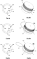
Fig. 1a is an elevation view of a coupling system according to an embodiment of the invention, particularly showing a container neck portion and a closure in a manufactured closed state A of a container opening; -
Fig. 1b is a cross-sectional view, according to a diametrical section plane, of the framed portion of the closure of theFig. 1 ; -
Figs. 2a and 2b are perspective views of the closure and of the container neck portion, respectively, before their first mutual engagement; -
Figs. 3a and 3b are perspective and elevation views, respectively, showing the same coupling system after a closure shell of the closure has been unscrewed and frangible connections provided therein have been broken determining an unattached tether; -
Figs. 4a to 4c are simplified schematic views of a set formed by a container neck portion and a closure shell, in each figure adopting different relative positions, wherein reference finish and closure leads beginning points as well as first and second auxiliar finish and closure leads beginning points have been identified and properly labelled; and -
Figs. 5a to 5c are perspective views of the closure system being the closure shell screwed on for reclosing the container opening by engaging the reference closure lead of the closure shell with i) the reference finish lead, ii) the first auxiliar finish lead and iii) the second auxiliar closure finish lead, respectively, of the container neck portion, in correspondence with the simplified schematic views of theFigs. 4a to 4c . - The drawings exemplify a closure system according to the invention. This
closure system 100 comprises apolymeric closure 2 and acontainer neck portion 1 mutually engageable. - The
container neck portion 1, that defines acontainer opening 11 with acentral axis 12, is provided with external threaded coupling means 13 and with anexternal shoulder 14 beneath said external threaded coupling means 13. The container can be made of a polymeric material and shaped as a bottle, such as a typical portable bottle storing a liquid product with a capacity of 1 liter. - The
closure 2 is of the type made of one-piece of polymeric material and is generally cylindrically shaped. Theclosure 2 has aclosure shell 20, having atop wall portion 21 and anannular skirt portion 22 provided with internal threated coupling means 23 mating with the external threaded coupling means 13 of theneck portion 1; and a bottom annular tamper-evident band 24. -
Fig. 1a shows theclosure system 100 in a manufactured closed state A of the container opening. TheFig. 1a is complemented with the detailed cross-sectional view of theFig. 1b . - As shown in the said
Fig. 1b , the annular tamper-evident band 24 is dimensioned to be anchored beneath theshoulder 14 and around alodging section 15 of theneck portion 1. This measure provides for a future axial retention of the tamper-evidence band 24 towards the container opening. To that effect, the tamper-evident band 24 may have an internal profile with acontinuous flange 24a or with discrete protrusions that, when the closure is first screwed on to close the container opening a snap engagement is established between the flange, or protrusions, of the annular tamper-evident band 24 and theshoulder 14 of thecontainer neck portion 1. These flange or protrusions may offer, for example, an introducing cam surface terminating in a flat engagement surface preferably perpendicular or essentially perpendicular to thecentral axis 12. The cam surface can be provided in an elastically deformable portion of the tamper-evident band 24. This is the case of thecontinuous flange 24 in the exemplary embodiment of theFig. 2b . - As shown in the
Figs. 1a , theannular skirt portion 22 of theclosure shell 20 has, in a manufactured closed state A of the container opening, a connectingstrip 3 encircling theclosure shell 20 between theannular skirt portion 22 and the tamper-evident band 24, thestrip 3 having anupper edge 31 attached to the annular skirt portion along an upperfrangible connection 31a and alower edge 32 attached to the tamper-evident band along a lowerfrangible connection 32a. These frangible connections are intended to be broken when theclosure shell 20 is unscrewed for the first time. - Specifically, the unscrew of the
closure shell 20 during a first opening operation of the container opening starting from the manufactured closed state A displaces theannular skirt portion 22 upwards while the tamper-evident band 24 is axially retained in thecontainer neck portion 1 and this results in rupture of the upper and the lowerfrangible connections 31a, 31b, the connectingstrip 3 forming then theunattached tether 33. Thistether 33 is showed in theFigs. 3a and 3b . - The upper and the lower
frangible connections 31a, 31b can be implemented by way of scoring lines, notches, leaders, lines of weaknesses, rows of pins, etc, formed (for example, moulded by sliders) or practiced (for example, laser scored) in the material conforming theclosure shell 20, which can be selected, for example, from high density polyethylene (HDPE), polyethylene (PE), polypropylene (PP), Polyethylene terephthalate (PET) or blends thereof. - The
Fig. 3b particularly shows how the practical length L of thetether 33 is determined by the overlapping length of the upper and the lowerfrangible connections proximal end 31a' of the upperfrangible connection 31a, adjacent to the permanent connection of thetether 33 with theannular skirt portion 22, and theproximal end 32a' of the lowerfrangible connection 32a, adjacent to the permanent connection of thetether 33 with the tamper-evidence band 24, as illustrated in theFig. 3b . - Certainly, the upper and the lower
frangible connections closure system 100. As will be explained in more detail hereinafter, the invention envisages dimensioning D1 to be greater than 150. - Regarding the mating external and
internal thread formations Figs. 2a and 2b , theclosure system 100 deploys its potential when they include at least three leads each, in combination to a specific engagement of the tamper-evident band 24 in thelodging section 15 of theneck portion 1 and a proper selection of D1, preferably for a specific range of diameter dimensions of theclosure 2, which in turn give rise to specific lengths L for thetether 33. - In the embodiment exemplifying the invention, the
external thread formation 13 has a number of three finish leads having respective beginning points, in the proximity of the opening edge of thecontainer opening neck 1, located roughly 120 degrees apart from each other: areference finish lead 13a with abeginning point 13a', a firstauxiliar finish lead 13b with abeginning point 13b' and a second auxiliar finish lead 13cwith abeginning point 13c', beginning points identified and properly labelled in the schemes of theFigs. 4a to 4c . - In correspondence with the
external thread formation 13 of thecontainer neck portion 1, theinternal thread formation 23 of theannular skirt portion 22 of theclosure shell 20 includes areference closure lead 23a and at least a first and a second auxiliar closure leads 23b, 23c in the counterclockwise order. - In the embodiment exemplifying the invention, the
internal thread formation 23 has a number of three closure leads having respective beginning points, in the proximity of thestrip 3, also located roughly 120 degrees apart from each other: areference closure lead 23a with abeginning point 23a', a firstauxiliar closure lead 23b with abeginning point 23b' and a secondauxiliar closure lead 23c with abeginning point 23c', beginning points identified and properly labelled as well in the schemes of theFigs. 4a to 4c . - Despite the drawings show continuous leads, it is envisaged to opt for discrete or discontinuous leads.
- It is a characterizing feature of the
closure system 100 that the tamper-evident band 24 and thelodging section 15 of theneck portion 1 are configured to provide for a strong grip between them so as to impede the free rotation of the tamper-evident band 24 during the first and subsequent opening operations of the container opening. That is, not only theshoulder 14 of thecontainer neck portion 1 provides for an axial retention of the tamper-evident band 24 but also the said tamper-evident band 24 and thelodging section 15 of thecontainer neck portion 1, which includes the above-mentionedshoulder 14, mechanically interfere each other to impede the free rotation of the tamper-evident band 24 relative to thecontainer neck portion 1. - This anti-rotation effect can be achieved simply by friction. It is also envisaged to provide the
lodging section 15, including theshoulder 14, and/or the tamper-evident band 24 with anchoring means or anti-return means, stoppers, or the like, blocking the movement of the tamper-evident band 24 al least in the counterclockwise direction. - Dimensioning the inner cross section of the annular tamper-
evident band 24 to be less than that of the outer cross section of thelodging section 15 may be sufficient, taking advantage of the elastic properties offered by the candidate materials to manufacture the closure, which can be elastically deformed during a first coupling of the closure to the container neck portion, so that the tamper-evident band 24 be pressed tightly around the saidlodging section 15 through restoring forces. This tightly adjustment is provided, in the exemplary embodiment of the invention, by the elastically deformablecontinuous flange 24a formed in the tamper-evident band 24. - To exemplify the invention, it has been selected an embodiment of the invention wherein D1 is 270; the length L of the
tether 33 is 94 mm (corresponding to aclosure 2 of about 38 mm diameter); and the set of leads, either of theexternal thread formation 13 or of theinternal thread formation 23, extend in a helical fashion and are configured to have to rotate theclosure shell 20 R1 degrees about thecentral axis 12, to unscrew or screw it completely, wherein R1 is 200. - The operation of this embodiment is the following:
- In the referred manufactured closed state A the
reference finish lead 13a and thereference closure lead 23a are the ones engaged each other. - When the
closure shell 20 is unscrewed about 200 degrees anticlockwise to reveal the container opening the upper and the lowerfrangible connections tether 33 is exposed when theclosure shell 20 is removed from thecontainer neck portion 1 thus opening the container. - It is worth mentioning that, because of the strong grip provided between the tamper-
evident band 24 and thelodging section 15 of thecontainer neck portion 1 impedes the free rotation of the former in respect of the latter, theproximal end 32a' of the lowerfrangible connection 32a, and therefore the point from which thetether 33 extends, remains static relative to thecontainer neck portion 1. - To re-close the container opening, the user is offered three options.
- i) If the user engages again the
reference finish lead 13a with thereference closure lead 23a (facing theclosure shell 20 and thecontainer neck portion 1 as shown in theFig. 4a ) and the closure shell is screwed on about 200 degrees clockwise, thetether 33 will naturally adopt theoriginal strip 3 form surrounding theclosure shell 20, held adjacent to thecontainer neck portion 1, without protruding outwards.
This non-protruding state of thetether 33 is shown in theFig. 5a . - ii) If the user does not engage again the
reference closure lead 23a with thereference finish lead 13a but with the firstauxiliar finish lead 13b (facing theclosure shell 20 and thecontainer neck portion 1 as shown in theFig. 4b ) and the closure shell is screwed on about 200 degrees clockwise, thetether 33 will naturally adopt a first exposed state B1, determining a protruding handle.- This is because, while the point from which the
tether 33 extends remains static relative to thecontainer neck portion 1, theproximal end 31a' of the upperfrangible connection 31a, and therefore the point from which thetether 33 extends from theclosure shell 20, will terminate at a closer position to the point from which thetether 33 extends from thecontainer neck portion 1, approximately 120 degrees closer in comparison to the option i), which means that the opposite ends of thetether 33 will be at 150 degrees each other with respect to thecentral axis 12. - This first exposed state B1 of the
tether 33 is shown inFig. 5b .
- This is because, while the point from which the
- iii) If the user does not engage again the
reference closure lead 23a with thereference finish lead 13a but with the secondauxiliar finish lead 13c (facing theclosure shell 20 and thecontainer neck portion 1 as shown in theFig. 4b ) and the closure shell is screwed on about 200 degrees clockwise, thetether 33 will naturally adopt a second exposed state B2, determining a more elongated protruding handle.- In this case, the point from which the
tether 33 extends from theclosure shell 20 will terminate approximately 240 degrees closer than before, we mean, in comparison to the option i). The opposite ends of thetether 33 will be at 30 degrees each other in respect of thecentral axis 12. - This second exposed state B2 of the
tether 33 is shown inFig. 5c . - As the reader will have noticed, this third option would only be possible if the value for D1 is greater than 240.
- This is due to the fact that, to re-close the container by selecting any of the options ii) and iii), it will be necessary to first counterclockwise rotate the
closure shell 20 200 degrees to unscrew it and then counterclockwise rotate theclosure shell 20 further degrees until thereference closure lead 23a of theclosure shell 20 is within reach of the firstauxiliar finish lead 13b or, if applicable, within reach of thesecond finish lead 13c of thecontainer neck portion 1.
- In this case, the point from which the
- i) If the user engages again the
- Other embodiments of the invention are conceived.
- In this sense, the following Table 1 gives further examples to put into practice a closure system according to the invention. These examples are based on a closure obtained from polyolefins and following a conventional process of compression molding or injection molding with molded bridges or slitting operations.
Table 1: Further exemplary embodiments of the closure system according to the invention D1 L (mm) R1 Number of leads per thread formation Appropriate for 150 37 180±25 3 Plastic bottles with a capacity from about 0,2L till 5 L (liters) 150 52 200±25 200 49 180±25 200 70 200±25 250 61 180±25 250 87 200±25 250 87 250±25 300 74 180±25 300 105 200±25 300 105 250±25 350 86 180±25 350 126 200±25 - In all of the above examples, the
strip 3, subsequently determining thetether 33, preferably have a minimum cross section of 1,5 mm2, and more preferably of 2 mm2. - The set of leads, for both the
external thread formation 13 and theinternal thread formation 23, extend in a helical fashion but, as indicated above, they can be configured to have to rotate theclosure shell 20 different R1 degrees about thecentral axis 12 to be fully unscrewed or screwed on. - As one can notice, D1 is always below 351. The upper and the lower
frangible connections closure shell 20, specifically along the entire circumference of theannular skirt portion 22. In all cases the upperfrangible connection 31a will extend around the circumference of theclosure shell 20 except in the area that eventually forms the permanent attachment of thetether 33 to theclosure shell 20; and the lowerfrangible connection 32a will extend around the circumference of theclosure shell 20 except in the area that eventually forms the permanent attachment of thetether 33 to the tamper-evidence band 24. Preferably, these permanent attachments extend at least along 5 degrees each about thecentral axis 12. Most preferably these permanent attachments extend at least along 10 degrees each about thecentral axis 12. It is not necessary that these permanent attachments to theclosure shell 20 and to the tamper-evident band 24 extend each along the same degrees. - In the example of the drawings, the upper and the lower
frangible connections strip 3 and a subsequentunattached tether 33 of a constant width along its length L. However, it is conceived to give to at least one or to both the upper and the lowerfrangible connections 31a and 32b a non-straight profile, for example, to increase the width of thetether 33 at a central portion thereof to improve the comfort of the handle. - Among the most suitable combinations of D1 and L, it is particular advantageous that in which D1 is approximately equal the R1 degrees the
closure shell 20 has to be rotated about thecentral axis 12 to be fully unscrewed and screwed on, because this gives the user a visual indication to engage again thereference finish lead 13a with thereference closure lead 23a, opting for re-closing according to the i) option, previously described. This visual indication it is no other than the coincidence of the two opposing ends of thetether 33. When the said opposed ends of the tether are axially aligned thereference finish lead 13a and thereference closure lead 23a will be engageable. - In the context of the present invention, D1 would be considered approximately equal to R1 when D1-R1 = ±15.
- Among the most suitable combinations of D1 and L, it is also particular advantageous that in which D1 is greater than R1 and D1>240 degrees when the number of leads per thread formation is three, distributed 120 degrees from form each other.
- In any case, it is conceived to incorporate visual indications in both the
closure shell 20 and the tamper-evident band 24 to provide the user with visual refences of how to screw on theclosure shell 20 in a re-closing operation leading to the option i) or to any of the further possible options (depending on the number of auxiliar finish and closure leads). - These visual indicators may be simple reliefs formed on the body of the
closure shell 20 and the tamper-evidence band 24. This reliefs may include numbers, strips, dots, geometric shapes, arrows, etc. or a combination thereof.
Claims (10)
- A closure system (100) comprising a container neck portion (1) and a closure (2) both with thread formations offering multiple angular distributed mutual engagement options to close the container neck portion(1), wherein the closure (2) has a closure shell (20) and a tamper-evident band (24) connected through frangible connections (31a, 32a) that break when the closure shell (20) and the container neck portion (1) are fully unengaged for the first time forming an unattached tether (33), characterized in thatbeing the tamper-evident band (24) anchored at a lodging section (15) of the container neck portion (1) the tamper-evident band (24) and the said lodging section (15) are further configured to provide for a strong grip between them, so as to impede the free rotation of the tamper-evident band (24) during the first and subsequent unengagement operations of the closure shell (20) and the container neck portion (1), and in thatthe length of the tether (33) is such that the closure system offers the user different re-closing options, one in which the tether (33) adopts a position encircling adjacent the container neck portion (1), without protruding; and at least one further option in which the tether (33) adopts an exposed state determining a protruding handle.
- A closure system (100) according to the claim 1, characterized in that the container neck portion (1) defines a container opening (11), with a central axis (12), and is provided with- an external thread formation (13) including a reference finish lead (13a) and at least a first and a second auxiliar finish leads (13b, 13c) in a counterclockwise order, and- an external shoulder (14) beneath said external thread formation (13), the closure (2), for closing the container opening (11), comprises- a closure shell (20) with a top wall portion (21) and an annular skirt portion (22) with an internal thread formation (23) mating with the external thread formation (13) of the neck portion (1) and including a reference closure lead (23a) and at least a first and a second auxiliar closure leads (23b, 23c) in a counterclockwise order,- the annular tamper-evident band (24) that is dimensioned to remain engaged beneath the external shoulder (14) and around the lodging section (15) of the container neck portion (1), and- a connecting strip (3) encircling the closure shell (20) between the annular skirt portion (22) and the tamper-evident band (24), having an upper edge (31) attached to the annular skirt portion (22) and a lower edge (32) attached to the tamper-evident band (24) along respective upper and lower frangible connections (31a, 32a) that overlap along at least D1 degrees around the closure shell (20) in a manufactured closed state (A) of the container opening (11) in which the reference finish lead (13a) and the reference closure lead (23a) are engaged each other,whereby the complete unscrew of the closure shell (20) during a first opening operation of the container opening (11) starting from the said manufactured closed state (A) results in the breaking or rupture of the upper and lower frangible connections (31a, 31b), the connecting strip (3) then forming the unattached tether (33) linking the unscrewed closure shell with the container neck portion (1), and whereinD1 is from 150 to 350,the length of the tether (33) is from 37 mm to 125 mm,such that when the closure shell (20) is screwed on to the container neck portion (1) during a re-closing operation of the container opening (11) by engaging the reference closure lead (23a) of the closure shell (20) with the first auxiliary finish lead (13b) instead of engaging it with the reference finish lead (13a) of the container neck portion (1), the tether (33) adopts an exposed state (B1) determining a protruding handle.
- A closure system (100) according to the claim 2, characterized in that D1 is enough to provide for at least two re-closing options wherein the tether (33) adopts respective different exposed states (B1, B2), specifically to enable a re-closing operation of the container opening (11) by engaging the reference closure lead (23a) of the closure shell (20) with any of the first and the second auxiliary finish leads (13b, 13c) of the container neck portion (1), the tether (33) transversally protruding more in the latter case.
- The closure system according to any one of the claims 2 or 3, characterized in that the closure shell (20) and the tamper-evidence band (24) incorporate visual indications to provide the user with visual references- to face the closure shell (20) and the container neck portion (1) to screw on the closure shell (20) during a re-closing operation of the container's opening (11) by mutually engaging the reference closure and finish leads (23a, 13a), and- to face the closure shell (20) and the container neck portion (1) to screw on the closure shell (20) during a re-closing operation of the container's opening (11) by mutually engaging the reference closure lead (23a) with at least one of the first or the second auxiliar finish leads (13b, 13c).
- The closure system according to any one of the claims 2 to 4, characterized in that being the mating external and internal thread formations (13, 23) configured such that the closure shell (20) has to be rotated R1 degrees to fully screw on the said closure shell (20) to the container neck portion (1), D1 is approximately equal to R1.
- The closure system according to any one of the claims 2 to 5, characterized in that in a set formed by the reference closure lead (23a) and the auxiliar closure leads (23b, 23c), the said leads are regularly phased shifted with respect to the central axis (12).
- The closure system according to any one of the claims 2 to 6, characterized in that the internal thread formation (23) has a number of three leads regularly phased shifted with respect to the central axis (12): the reference closure lead (23a), a first auxiliar closure lead (23b) and second auxiliar closure lead (23c).
- The closure system according to the previous claim, characterized in that D1 is greater than 240.
- The closure system according to any one of the claims 2 to 4, characterized in that- being the mating external and internal thread formations (13, 23) configured such that the closure shell (20) has to be rotated R1 degrees to fully screw on the said closure shell (20) to the container neck portion (1), D1 is greater than R1; and in that- having the internal thread formation (23) a number of three leads regularly phased shifted with respect to the central axis (12): the reference closure lead (23a), a first auxiliar closure lead (23b) and second auxiliar closure lead (23c), D1 is greater than 240.
- The closure system according to any one of the claims 1 to 9, characterized in that the width of the unattached tether (33) is increased at a central portion thereof.
Priority Applications (5)
| Application Number | Priority Date | Filing Date | Title |
|---|---|---|---|
| EP21382177.0A EP4053035B1 (en) | 2021-03-03 | 2021-03-03 | A tethered closure system |
| US18/279,332 US11939125B2 (en) | 2021-03-03 | 2022-02-23 | Tethered closure system |
| PCT/EP2022/054566 WO2022184528A1 (en) | 2021-03-03 | 2022-02-23 | A tethered closure system |
| BR112023016583A BR112023016583A2 (en) | 2021-03-03 | 2022-02-23 | Closing system provided with lashing tape |
| CONC2023/0012004A CO2023012004A2 (en) | 2021-03-03 | 2023-09-11 | A closure system with a tie strap |
Applications Claiming Priority (1)
| Application Number | Priority Date | Filing Date | Title |
|---|---|---|---|
| EP21382177.0A EP4053035B1 (en) | 2021-03-03 | 2021-03-03 | A tethered closure system |
Publications (3)
| Publication Number | Publication Date |
|---|---|
| EP4053035A1 EP4053035A1 (en) | 2022-09-07 |
| EP4053035B1 true EP4053035B1 (en) | 2024-05-22 |
| EP4053035C0 EP4053035C0 (en) | 2024-05-22 |
Family
ID=75223249
Family Applications (1)
| Application Number | Title | Priority Date | Filing Date |
|---|---|---|---|
| EP21382177.0A Active EP4053035B1 (en) | 2021-03-03 | 2021-03-03 | A tethered closure system |
Country Status (5)
| Country | Link |
|---|---|
| US (1) | US11939125B2 (en) |
| EP (1) | EP4053035B1 (en) |
| BR (1) | BR112023016583A2 (en) |
| CO (1) | CO2023012004A2 (en) |
| WO (1) | WO2022184528A1 (en) |
Families Citing this family (1)
| Publication number | Priority date | Publication date | Assignee | Title |
|---|---|---|---|---|
| WO2021067412A1 (en) | 2019-09-30 | 2021-04-08 | Berry Global, Inc. | Retainable closure |
Family Cites Families (11)
| Publication number | Priority date | Publication date | Assignee | Title |
|---|---|---|---|---|
| FR2329536A1 (en) | 1973-07-02 | 1977-05-27 | Somepla Sa | NEW TIGHT AND TAPPED SCREW CAPSULE |
| SI20739A (en) * | 2000-11-28 | 2002-06-30 | G.Loc, Trgovina In Storitve D.O.O. | A cap of a container, especially bottle or plastic bottle |
| CN1830730A (en) | 2005-01-01 | 2006-09-13 | 郭永军 | Hinge type antitheft bottle cap |
| CN1631740A (en) | 2005-01-01 | 2005-06-29 | 郭永军 | Articulated anti-theft bottle cap |
| CN208264903U (en) * | 2018-04-09 | 2018-12-21 | 宏全国际股份有限公司 | Zonate environment protection bottle cap |
| ES1258400Y (en) * | 2018-04-26 | 2021-03-08 | Obrist Closures Switzerland | Closing |
| US20190375557A1 (en) | 2018-06-12 | 2019-12-12 | Closure Systems International Inc. | Tethered Closure |
| ES1218754Y (en) * | 2018-08-09 | 2019-01-10 | Betapack S A U | BOTTLE PLUG |
| CH715478A1 (en) * | 2018-10-29 | 2020-04-30 | Alpla Werke Alwin Lehner Gmbh & Co Kg | Cap for closing a container and container with such a captive cap. |
| WO2020099199A1 (en) | 2018-11-16 | 2020-05-22 | Bericap Holding Gmbh | Captive closure |
| WO2020182854A1 (en) | 2019-03-11 | 2020-09-17 | Alpla Werke Alwin Lehner Gmbh & Co. Kg | Container closure and container |
-
2021
- 2021-03-03 EP EP21382177.0A patent/EP4053035B1/en active Active
-
2022
- 2022-02-23 BR BR112023016583A patent/BR112023016583A2/en unknown
- 2022-02-23 US US18/279,332 patent/US11939125B2/en active Active
- 2022-02-23 WO PCT/EP2022/054566 patent/WO2022184528A1/en active Application Filing
-
2023
- 2023-09-11 CO CONC2023/0012004A patent/CO2023012004A2/en unknown
Also Published As
| Publication number | Publication date |
|---|---|
| WO2022184528A1 (en) | 2022-09-09 |
| CO2023012004A2 (en) | 2023-09-29 |
| BR112023016583A2 (en) | 2023-09-26 |
| EP4053035A1 (en) | 2022-09-07 |
| EP4053035C0 (en) | 2024-05-22 |
| US11939125B2 (en) | 2024-03-26 |
| US20240034527A1 (en) | 2024-02-01 |
Similar Documents
| Publication | Publication Date | Title |
|---|---|---|
| CN112996733B (en) | Twist and flip lock closure | |
| CA1199005B (en) | Resealable pour bottle with severing ring | |
| EP3305680B1 (en) | Stopper for containers | |
| EP3820783B1 (en) | Twist and flip closure | |
| AU661947B2 (en) | Single walled dispensing closures with positive alignment means | |
| CA1227457A (en) | Safety closure | |
| US8123056B2 (en) | Closure arrangement with opening indicating (anti-tamper) elements | |
| EP4090604B1 (en) | Package with tethered closure | |
| US20030062369A1 (en) | Snap-hinge closure with tamper-evident lid and method of making | |
| AU2002246339B2 (en) | Screw cap of synthetic resin | |
| US10829274B2 (en) | Flip-top closure | |
| EP3670377B1 (en) | Capping device that is affixed to the neck of a container | |
| US11939125B2 (en) | Tethered closure system | |
| CN113795433A (en) | Container lid and container | |
| JP4349698B2 (en) | Plastic cap | |
| JPH08183547A (en) | Connecting structure between container and container lid made of synthetic resin | |
| EP2943418B1 (en) | Cap with tamper evident seal for containers, container comprising said cap and preform for producing said container | |
| JPS6111357A (en) | Vessel cover having pilfer-proof characteristic | |
| EP2045192A1 (en) | Flip-top dispensing closure | |
| JPS6218420B2 (en) | ||
| WO2005058722A2 (en) | Container closure | |
| JPH0442253B2 (en) | ||
| JP2019142554A (en) | Container lid | |
| JPS62122956A (en) | Vessel cover made of olefin group resin | |
| JPH04128251U (en) | Container with pilfer-proof cap |
Legal Events
| Date | Code | Title | Description |
|---|---|---|---|
| PUAI | Public reference made under article 153(3) epc to a published international application that has entered the european phase |
Free format text: ORIGINAL CODE: 0009012 |
|
| STAA | Information on the status of an ep patent application or granted ep patent |
Free format text: STATUS: THE APPLICATION HAS BEEN PUBLISHED |
|
| AK | Designated contracting states |
Kind code of ref document: A1 Designated state(s): AL AT BE BG CH CY CZ DE DK EE ES FI FR GB GR HR HU IE IS IT LI LT LU LV MC MK MT NL NO PL PT RO RS SE SI SK SM TR |
|
| TPAC | Observations filed by third parties |
Free format text: ORIGINAL CODE: EPIDOSNTIPA |
|
| STAA | Information on the status of an ep patent application or granted ep patent |
Free format text: STATUS: REQUEST FOR EXAMINATION WAS MADE |
|
| 17P | Request for examination filed |
Effective date: 20230220 |
|
| RAX | Requested extension states of the european patent have changed |
Extension state: ME Payment date: 20230220 Extension state: BA Payment date: 20230220 |
|
| RBV | Designated contracting states (corrected) |
Designated state(s): AL AT BE BG CH CY CZ DE DK EE ES FI FR GB GR HR HU IE IS IT LI LT LU LV MC MK MT NL NO PL PT RO RS SE SI SK SM TR |
|
| GRAP | Despatch of communication of intention to grant a patent |
Free format text: ORIGINAL CODE: EPIDOSNIGR1 |
|
| STAA | Information on the status of an ep patent application or granted ep patent |
Free format text: STATUS: GRANT OF PATENT IS INTENDED |
|
| INTG | Intention to grant announced |
Effective date: 20240108 |
|
| GRAS | Grant fee paid |
Free format text: ORIGINAL CODE: EPIDOSNIGR3 |
|
| RAP3 | Party data changed (applicant data changed or rights of an application transferred) |
Owner name: CAP SUSTAINBLE SOLUTIONS S.L.U. |
|
| GRAA | (expected) grant |
Free format text: ORIGINAL CODE: 0009210 |
|
| STAA | Information on the status of an ep patent application or granted ep patent |
Free format text: STATUS: THE PATENT HAS BEEN GRANTED |
|
| AK | Designated contracting states |
Kind code of ref document: B1 Designated state(s): AL AT BE BG CH CY CZ DE DK EE ES FI FR GB GR HR HU IE IS IT LI LT LU LV MC MK MT NL NO PL PT RO RS SE SI SK SM TR |
|
| REG | Reference to a national code |
Ref country code: GB Ref legal event code: FG4D |
|
| REG | Reference to a national code |
Ref country code: CH Ref legal event code: EP |
|
| REG | Reference to a national code |
Ref country code: DE Ref legal event code: R096 Ref document number: 602021013547 Country of ref document: DE |
|
| REG | Reference to a national code |
Ref country code: IE Ref legal event code: FG4D |
|
| U01 | Request for unitary effect filed |
Effective date: 20240527 |
|
| U07 | Unitary effect registered |
Designated state(s): AT BE BG DE DK EE FI FR IT LT LU LV MT NL PT SE SI Effective date: 20240606 |