JP4349698B2 - Plastic cap - Google Patents
Plastic cap Download PDFInfo
- Publication number
- JP4349698B2 JP4349698B2 JP23717699A JP23717699A JP4349698B2 JP 4349698 B2 JP4349698 B2 JP 4349698B2 JP 23717699 A JP23717699 A JP 23717699A JP 23717699 A JP23717699 A JP 23717699A JP 4349698 B2 JP4349698 B2 JP 4349698B2
- Authority
- JP
- Japan
- Prior art keywords
- circumferential band
- cap
- bridge
- container mouth
- circumferential
- Prior art date
- Legal status (The legal status is an assumption and is not a legal conclusion. Google has not performed a legal analysis and makes no representation as to the accuracy of the status listed.)
- Expired - Fee Related
Links
Images


Classifications
-
- B—PERFORMING OPERATIONS; TRANSPORTING
- B65—CONVEYING; PACKING; STORING; HANDLING THIN OR FILAMENTARY MATERIAL
- B65D—CONTAINERS FOR STORAGE OR TRANSPORT OF ARTICLES OR MATERIALS, e.g. BAGS, BARRELS, BOTTLES, BOXES, CANS, CARTONS, CRATES, DRUMS, JARS, TANKS, HOPPERS, FORWARDING CONTAINERS; ACCESSORIES, CLOSURES, OR FITTINGS THEREFOR; PACKAGING ELEMENTS; PACKAGES
- B65D41/00—Caps, e.g. crown caps or crown seals, i.e. members having parts arranged for engagement with the external periphery of a neck or wall defining a pouring opening or discharge aperture; Protective cap-like covers for closure members, e.g. decorative covers of metal foil or paper
- B65D41/32—Caps or cap-like covers with lines of weakness, tearing-strips, tags, or like opening or removal devices, e.g. to facilitate formation of pouring openings
- B65D41/34—Threaded or like caps or cap-like covers provided with tamper elements formed in, or attached to, the closure skirt
- B65D41/3423—Threaded or like caps or cap-like covers provided with tamper elements formed in, or attached to, the closure skirt with flexible tabs, or elements rotated from a non-engaging to an engaging position, formed on the tamper element or in the closure skirt
- B65D41/3428—Threaded or like caps or cap-like covers provided with tamper elements formed in, or attached to, the closure skirt with flexible tabs, or elements rotated from a non-engaging to an engaging position, formed on the tamper element or in the closure skirt the tamper element being integrally connected to the closure by means of bridges
- B65D41/3433—Threaded or like caps or cap-like covers provided with tamper elements formed in, or attached to, the closure skirt with flexible tabs, or elements rotated from a non-engaging to an engaging position, formed on the tamper element or in the closure skirt the tamper element being integrally connected to the closure by means of bridges with drive means between closure and tamper element
Description
【0001】
【発明の属する技術分野】
本発明は、開封明示機能、即ち一般にタンパーエビデント(TE)特性といわれる機能と、分別廃棄機能とを有するプラスチックキャップの改良に関するものである。
【0002】
【従来の技術】
上記TE特性を有するプラスチックキャップは、キャップ本体の下部に破断可能なブリッジを介して周状バンド部が形成された構造を有している。この代表的なものは、周状バンド部の内面の部分が、容器首部外周の部分と係合することにより周状バンド部が固定され、キャップ本体の開栓に伴って前記ブリッジが破断してキャップ本体と周状バンド部とが切り離されるというものである。
【0003】
このようなプラスチックキャップの例として、特開昭57−28767号公報には、外周面に螺条と該螺条に隣接してその下方に位置するあご部とが形成されている容器口部を備えた容器のための、ピルフアープルーフ特性を有する合成樹脂製容器蓋であつて、天面と、該天面の周縁から垂下する筒状スカートとを具備し、該スカートには周方向に延ぴる破断ラインが形成されていて、該スカートは該破断ラインより上方の主部と該破断ラインより下方のピルフアープルーフ裾部とに区画されており、該主部の内面には、該容器口部の該螺条に螺合せしめられる螺条が形成されているところの容器蓋において、該ピルフアープルーフ裾部の内面には該容器口部の該あご部に係合せしめられる半径方向内方に突出した突条が形成され、そして該ピルフアープルーフ裾部には軸線方向に延びる少なくとも1個の軸線方向スリットが形成されていることを特徴とする容器蓋が記載されている。
【0004】
また、特公平4−40267号公報には、外周面に雄螺条と該雄螺条の下方に位置する係止あご部とが形成されている口頸部を具備する容器のための、ピルフアープルーフ特性を有する合成樹脂製容器蓋であつて、天面壁と該天面壁の周縁から垂下する筒状スカート壁とを具備し、該スカート壁には周方向に延ぴる周方向弱化ラインが形成されていて、該スカート壁は該周方向弱化ラインより上方の主部と該周方向弱化ラインより下方のピルフアープルーフ裾部とに区画されており、該主部の内面には、該口頸部の該雄螺条に螺合せしめられる雌螺条が形成され、該ピルフアープルーフ裾部の内面には、該口頸部の該係止あご部に係合せしめられる係止手段が形成され、そして更に、該ピルフアープルーフ裾部には、軸線方向に延びる軸線方向弱化ラインが形成されているところの容器蓋において;該軸線方向弱化ラィンは材料厚さが低滅せしめられたスコアから構成されており、該スコアの上端部においては残留材料厚さが上方に向つて漸次減少せしめられている、ことを特徴といする容器蓋が記載されている。
【0005】
【発明が解決しようとする課題】
これらの公知のプラスチックキャップにおいては、キャップ本体と周状バンドとが破断可能なブリッジを介して連結され、しかも前記周状バンドにはこれを容器口部から取り外すための垂直方向弱化部が形成されているものであり、前記第一の従来例では、破断された周状バンドはキャップ本体から分離された状態で容器口部に残るようにすることも、また周状バンドの一部がキャップ本体に連結した状態で容器口部から取り外すことが可能なことも記載されている。
しかしながら、破断された周状バンドがキャップ本体から分離された状態で容器口部に残るようなプラスチックキャップ(以下単に分離型キャップと呼ぶことがある)では、周状バンドの容器口部からの取り外しが必ずしも容易ではないという問題がある。
【0006】
従来、プラスチックキャップ付のボトルでは、内容物を使い切るまで、何回でもリシールして使用可能であるという特徴があり、この目的に使用されるキャップ付ボトルでは、デザイン上、周状バンドが廃棄する前までボトル口部に残っていることが望まれる場合も多い。
【0007】
一方、ゴミの廃棄量を削減し、資源を有効に再利用するという見地から、分別廃棄の要請があり、この要請に沿うためには、上述したキャップ付ボトルでも、ボトルの廃棄に先立って口部に残留する周状バンドを取り外すことが必要となる。
【0008】
ところが、前述した分離型キャップでは、周状バンドの容器口部からの取り外し作業性と、確実な閉栓作業性乃至タンパーエビデント性とが両立しがたいという問題があることが分かった。
即ち、閉栓に際して周状バンドはキャップ本体と共に容器口部に挿入され且つネジで係合されて、容器口部のあご部に係止されるものであるため、周状バンドの垂直方向弱化部が、容器口部からの取り外しが容易に行われるように弱化されていると、閉栓操作に際して垂直方向弱化部の破壊が生じて、閉栓作業が困難となったり、タンパーエビデント性が得られないという事態を招き、一方、周状バンドの垂直方向弱化部が、閉栓操作が失敗なしに確実に行われるような強度を有する場合には、容器口部からの周状バンドの取り外しが簡単に行えないという問題を発生する。
【0009】
したがって、本発明の目的は、周状バンドの容器口部からの取り外し作業性と、確実な閉栓作業性乃至タンパーエビデント性とが両立したプラスチックキャップを提供するにある。
【0010】
【課題を解決するための手段】
本発明によれば、
頂板部とスカート部とからなり且つスカート部内周壁には容器口部のネジと係合するネジを備えたキャップ本体と、スカート部下方に位置し且つ開栓に際して容器口部のあご部に係止される周状バンドと、スカート部下端と周状バンドとの接続部とからなり、前記接続部は周状に分布して配置された複数の破断可能なブリッジと、前記ブリッジ間に配置されたスカート部下端と周状バンドとの垂直方向及びキャップの閉栓方向への係止部とからなり、開栓に際しては前記周状バンドが容器口部に保持されるプラスチックキャップにおいて、
前記周状バンドには取り外しのための弱化部が上下方向に形成され、前記弱化部は、切り欠き部と少なくとも1個の薄肉連結部とからなり且つ前記薄肉連結部は周状バンドの少なくとも下側に形成され、
前記弱化部に対し、周状バンドの開栓方向側端部乃至その近傍に破断可能なブリッジが位置し且つ周状バンドの閉栓方向側端部からブリッジが離隔して位置するように、両ブリッジが前記弱化部に対して非対称に配置され、
前記弱化部に対し開栓方向側バンド端部乃至その近傍に位置するブリッジとこのブリッジの閉栓方向側に隣り合ったブリッジとの間に、スカート部下端と周状バンドとのキャップの閉栓方向への係止部が位置しており、且つ前記弱化部に対し開栓方向側バンド端部乃至その近傍に位置するブリッジとこのブリッジの開栓方向側に隣り合ったブリッジとの間に、スカート部下端と周状バンドとの垂直方向への係止部が位置している、ことを特徴とするプラスチックキャップが提供される。
本発明のキャップにおいては、
1.前記薄肉連結部が周方向に厚みが減少する勾配を有していること、
2.前記周状バンドの容器口部のあご部への係止手段が上下に折り曲げ可能な周状のフラップ片であり、該フラップ片が中心側から周状バンドの内面に径方向に延びる幅の広い切り欠き部により周方向に分割されており且つ幅広の切り欠き部間にフラップ片の先端から付け根への途中に至る幅の狭い切り欠き部を備えているとともに、前記弱化部が幅広の切り欠き部に重なる位置にあること、
3.前記弱化部がスカート部の垂直方向にネジが1条で存在する部分に設けられていること、
が好ましい。
本発明によればまた、
上記プラスチックキャップと、該プラスチックキャップ内に収納され、容器口部を密封する中栓とからなり、
前記中栓は、容器口部が挿入される溝を備えたフランジ部と、フランジ部の下部の内周側に形成された水平壁と、フランジ部の内周上部に設けられた注ぎ口と、水平壁の開口予定部と、開口予定部を区画する開口用スコアと、開口予定部に設けられた開口用タブとから形成されており、
前記フランジ部の下部内周には下方への筒状延長部からなる容器口部のガイドが形成されており、
前記フランジ部の外周下部には薄片状の突起部が形成されており、プラスチックキャップのネジの上部にはこの薄片状突起部と係止可能な環状突起部が形成されていることを特徴とする中栓付プラスチックキャップが提供される。
【0011】
【発明の実施形態】
本発明のプラスチックキャップは、頂板部とスカート部とからなり且つスカート部内周壁には容器口部のネジと係合するネジを備えたキャップ本体と、スカート部下方に位置し且つ開栓に際して容器口部のあご部に係止される周状バンドと、スカート部下端と周状バンドとの接続部と、前記接続部は周状に分布して配置された複数の破断可能なブリッジと、前記ブリッジ間に配置されたスカート部下端と周状バンドとの垂直方向及びキャップの閉栓方向への係止部とからなっていて、開栓に際しては前記周状バンドが容器口部に残留、保持されるものであるが、
1)周状バンドには取り外しのための弱化部を上下方向に形成したこと、
2)前記弱化部を薄肉部或いは該薄肉部と切り欠き部との組合せから構成したこと、及び
3)前記弱化部に対し、周状バンドの開栓方向側端部乃至その近傍に破断可能なブリッジが位置し且つ周状バンドの閉栓方向側端部からブリッジが離隔して位置するように、両ブリッジを弱化部に対して非対称に配置したこと、
が特徴である。
【0012】
上記分離型のプラスチックキャップにおいて、容器口部に残留、保持される周状バンドを、廃棄に際して容器口部から取り外し、分別廃棄を可能とするためには、周状バンドに上下方向の弱化部を形成させることが必須不可欠である。
また、この弱化部の構造としては、この部分を薄肉部或いは薄肉部と切り欠き部との組合せとすることが取り外しのための応力を小さくする上で好ましい。
【0013】
ところが、弱化部を、薄肉部或いは薄肉部と切り欠き部との組合せの構造とすると、閉栓に際して、この薄肉部に応力集中が生じて、この部分が破損するという問題を生じる。
一般に、キャップ本体と周状バンドとがブリッジで接続され且つ周状バンドに弱化部が形成された分離型のプラスチックキャップでは、特開昭57−28767号公報の第三図に示されるように、一対のブリッジの中間に垂直方向弱化部を設けるのが一般的であるが、このようなブリッジと弱化部との構造では、閉栓時の応力集中による弱化部の破壊が頻繁に起こることが認められた。
【0014】
これに対して、本発明では、前記弱化部に対し、周状バンドの開栓方向側端部乃至その近傍にブリッジが位置し且つ周状バンドの閉栓方向側端部からブリッジが離隔して位置するように、両ブリッジを弱化部に対して非対称に配置することにより、閉栓時の応力集中による破損を防止しながら、容器口部からの周状バンドの取り外しを容易に行うことができる。
【0015】
この理由は次のように考えられる。
即ち、一対のブリッジの中間に上下方向弱化部を設けたブリッジ−弱化部の構造では、ブリッジを通して流入する樹脂が合流する部分に薄肉弱化部が形成されるため、この薄肉弱化部にウエルドの影響がでやすく、これが強度低下の原因となる。これに対して、本発明では、弱化部に対し、周状バンドの開栓方向側端部乃至その近傍にブリッジが位置し且つ周状バンドの閉栓方向側端部からブリッジが離隔して位置するように、両ブリッジを弱化部に対して非対称に配置することにより、ウエルドが薄肉弱化部以外の厚肉の周状バンドに形成され、薄肉弱化部の強度低下を防止できるものと認められる。
また、閉栓に際して、周状バンドは容器口部のあご部を乗り越えてあご部と係合するものであるため、周状バンドは閉栓に際して径外方向に広がろうとする傾向があり、この傾向は、弱化部に対し開栓方向側に位置するバンド端部において最も顕著である。本発明においては、弱化部に対し開栓方向側に位置するバンド端部乃至その近傍にブリッジを配置したため、周状バンドの開栓方向側端部が径外方向に広がるのが抑制され、これにより薄肉弱化部の破損を防止できるものと考えられる。
尚、本明細書においては、弱化部に対し開栓方向側に位置するバンド端部乃至その近傍に設けられたブリッジを、その位置及び作用に注目して、弱化部保護ブリッジと呼ぶが、この弱化部保護ブリッジが他のブリッジに比して断面積が特に大きく設けられていることを意味するものではない。
【0016】
本発明のキャップにおいては、弱化部に対して非対称にブリッジを配置したため、弱化部に対し開栓方向側バンド端部乃至その近傍に位置するブリッジとこのブリッジの閉栓方向側に隣り合ったブリッジとの間に、スカート部下端と周状バンドとのキャップの閉栓方向への係止部を配置することが可能となり、この係止部により弱化部回りの周状バンドの閉栓方向への回動を円滑に行うことができる。
【0017】
また、弱化部に対し開栓方向側バンド端部乃至その近傍に位置するブリッジ(弱化部保護ブリッジ)とこのブリッジの開栓方向側に隣り合ったブリッジとの間に、スカート部下端と周状バンドとの垂直方向への係止部を配置することが好ましく、この垂直方向係止部は、閉栓に際して、周状バンドの係止部を容器口部のネジ及びあご部を乗り越えてあご部と係合させる際、弱化部保護ブリッジを破損から守る作用がある。
【0018】
更に、本発明のキャップでは、前記弱化部を、切り欠き部と厚みの減少された少なくとも1個の連結部とから形成し、しかもこの連結部を周状バンドの少なくとも下側に設けるのが好ましい。即ち、弱化部に設けた切り欠き部は周状バンドの取り外しに必要な力を減少させるのに有効であり、一方周状バンドの下側に設けられた薄肉連結部は、キャップ閉栓時に周状バンドが径外方向に広がるのを防止する作用がある。
【0019】
上記の薄肉部乃至薄肉連結部は、周方向に厚みが減少する勾配を有していること、特に弱化部に対し開栓方向側に位置する周状バンドの端部に向けて厚みが減少するような勾配を有することが好ましい。
上記のような厚みの勾配を薄肉部乃至薄肉連結部に設けることにより、容器口部に残留する周状バンドの取り外しに際して、最薄肉部に取り外しの力が集中し、周状バンドの破断を容易に行うことが可能となる。
【0020】
本発明のキャップでは、周状バンドが径内向に厚肉となった逆L字型断面構造の上端部を有することが好ましい。即ち、周状バンドの上端部を厚肉にすることにより、スカート部下端と周状バンドとの垂直方向及びキャップの閉栓方向への係止部を十分な面積にわたって形成でき、スカート部と周状バンドとの垂直方向及び閉栓方向への係合を確実且つ緊密に行うことが可能となる。
また、本発明のキャップでは、ブリッジの周囲に周状バンドの外周面と内周面とを貫通する窓部が形成されていることが好ましい。周状バンドの上記窓内にブリッジを設けることにより、ブリッジの成形が確実に行えると共に、上記窓部の外には、周状バンドの壁が存在するので、キャップ同士や異物との接触によるブリッジの偶発的な損傷が防止されることになる。
【0021】
更に、本発明において、周状バンドの容器口部のあご部への係止手段は、従来この種のキャップに一般的に用いられている任意の係止手段であってよいが、本発明の目的には、周状バンドの内周側下部に上下に折り曲げ可能に一体に設けられた周状のフラップ片であることが好ましい。このフラップ片は、上方に折り曲げられた状態で容器口部に挿入され、容器口部のあご部を乗り越えあご部の下部と係合することにより、周状バンドの容器口部への保持が可能となっている。
このフラップ片は、中心側から周状バンドの内面に径方向に延びる幅の広い切り欠き部により周方向に分割されており且つ幅広の切り欠き部間にフラップ片の先端から付け根への途中に至る幅の狭い切り欠き部を備えていることが好ましい。
幅広の切り欠き部はフラップ片の上下への折り曲げをを可能とするものであり、一方幅広の切り欠き部間に設けられた幅狭い切り欠き部はこの折り曲げを助ける補助作用を行うものである。
また、アセプティック充填用に用いる場合、キャップ内面の殺菌及び洗浄後に液を容易にキャップ外に排出することができる。
【0022】
この場合、周状バンドの弱化部はフラップ片の幅広の切り欠き部に重なる位置に設けることが、弱化部の保護の点及び周状バンドの取り外し廃棄の点で好ましい。即ち、弱化部をフラップ片の幅広の切り欠き部に重なる位置に設けることにより、フラップ片に加わる荷重が弱化部に加わるのが防止され、弱化部の保護が有効に行われる。
また、周状バンドの弱化部とフラップ片の幅広の切り欠き部とを上記のように対応させないと、フラップ片も切断しなければバンドを切ることができない。
【0023】
更に、閉栓時において弱化部を保護するには、弱化部がスカート部内面の容器口部との係合ネジの内、垂直方向にネジが一条で存在する部分に設けられていることが好ましい。一般にスカート部内面の容器口部との係合ネジには、ネジの始め及び終わりにある垂直方向に2条のネジが存在する部分とそれらの中間にある1条のネジの部分とがある。これらのネジの内2条のネジの部分では容器口部との締結による歪みの影響が大きくでるが、1条のネジに対応する部分に周状バンドの弱化部を設けることにより、歪みの影響が弱化部に及ぶのを有効に回避することができる。
【0024】
本発明ではまた、周状バンドには指の掛かりをよくするためのタブ或いは切り欠き部を設けることが、使用済み容器の口部から周状バンドの取り外しを容易に行うために好ましい。
【0025】
本発明のプラスチックキャップは、容器口部を密封する中栓を内部に収納した中栓付プラスチックキャップとして特に有用である。即ち、本発明のプラスチックキャップでは、ブリッジや周状バンド弱化部の破損を防止しながら比較的大きな締結トルクでの容器口部への巻締が可能となるため、閉栓の際に中栓を容器口部に確実に密封係合させることができ、しかも中栓と容器口部との密封係合状態は、プラスチックキャップの開栓後にも維持することができる。
このため、本発明の中栓付プラスチックキャップでは、周状バンドと中栓とによる二重のタンパーエビデント機能が達成される。
中栓は、容器口部が挿入される溝を備えたフランジ部と、フランジ部の下部の内周側に形成された水平壁と、フランジ部の内周上部に設けられた注ぎ口と、水平壁の開口予定部と、開口予定部を区画する開口用スコアと、開口予定部に設けられた開口用タブとから形成されていることが好ましく、プラスチックキャップを開栓した後、開口用タブを把持し、開口用スコアを破断して開口予定部を取り外し、注ぎ口を経て内容物を容器外に取り出すことができる。
【0026】
本発明の中栓付プラスチックキャップにおいては、フランジ部の下部内周には下方への筒状延長部からなる容器口部のガイドが形成されていることが好ましい。
上記の中栓は容器に保持された状態で使用されるため、中栓と容器との係合力が強固である。このため、キャップをネジ込みながら、容器内に挿入するときにかなりの抵抗を受ける。この抵抗により中栓が傾いたり、位置ずれを起こすことがあり、中栓の容器へのネジ込みが円滑に進行しがたい傾向がある。
本発明の中栓付きプラスチックキャップでは、キャップ内の中栓に若干の傾きなどがある場合でも、前記ガイドの作用により、容器口部がフランジ部の溝の中に確実に案内され、中栓の容器口部へのネジ込みに際しても中栓が容器口部へ正しく位置決めされ、中栓の容器口部への密封係合保持が確実に行えるという利点がある。
また、中栓フランジ部の外周下部には薄片状の突起部を形成すると共に、プラスチックキャップのネジの上部にはこの薄片状突起部と係止可能な環状突起部を形成すると、キャップの移送中や閉栓操作時に中栓が離脱することなくプラスチックキャップに確実に保持され、しかも中栓の突起部が薄片状であるため、開栓時にはキャップの環状突起部との係合状態が外れ、中栓を容器口部との密封状態を保ったまま容器口部に残すことが可能となる。
【0027】
【実施例】
本発明を添付図面に示す実施例に基づき以下に詳細に説明する。
添付図面において、
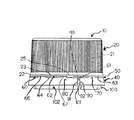
図1は本発明のキャップの一例の側面図であり、
図2は図1のキャップ(フラップ片を上方且つ内方に反転させる前の状態)の下面図であり、
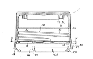
図3は図1のキャップの拡大側断面図であり、
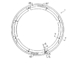
図4は図1のキャップの図3の線IV−IVにおける水平断面図であり、
図5は図1のキャップの図4の線V−Vにおける垂直断面図であり、
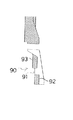
図6は図1のキャップの図4の線VI−VIにおける垂直断面図であり、
図7は図1のキャップの図4の線VII−VIIにおける垂直断面図であり、
図8は図1のキャップと組み合わせで用いる中栓の断面図であり、
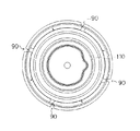
図9は図8の中栓の上面図であり、
図10は図1のキャップ(フラップ片を反転後)及び図8の中栓を容器口部に締結した状態を示す断面図であり、
図11は本発明のキャップ(フラップ片を上方且つ内方に反転させる前の状態)の他の例の側面図であり、
図12は本発明のキャップ(フラップ片を上方且つ内方に反転させる前の状態)の更に他の例の側面図であり、
図13は図12のキャップの下面図である。
【0028】
本発明のプラスチックキャップの1実施例を示す図1及び図2において、
このキャップは、頂板部10とスカート部20とからなり且つスカート部20内周壁には容器口部のネジと係合するネジ30(図3)を備えたキャップ本体1と、スカート部下方に位置し且つ開栓に際して容器口部のあご部に係止される係止手段100を備えた周状バンド40と、スカート部20の下端と周状バンド40との接続部50と、前記接続部に周状に分布して配置された複数の破断可能なブリッジ60と、前記ブリッジ60間に配置されたスカート部下端と周状バンドとの垂直方向の係止部70及びキャップの閉栓方向への係止部80と、前記周状バンド40に設けられた取り外しのための上下方向弱化部90とから成っている。この具体例において、上下方向弱化部90は垂直方向に設けられているが、上下に傾斜して設けられていてもよい。
【0029】
本発明のキャップでは、この上下方向弱化部90に対し、周状バンドの開栓方向(図1において右方向)側端部乃至その近傍にブリッジ61を設け且つ周状バンドの閉栓方向(図1において左方向)側端部から閉栓方向に離隔してブリッジ62を設け、弱化部90に対してブリッジ61、62を非対称に配置することにより、閉栓時の応力集中による破損を防止しながら、容器口部からの周状バンドの取り外しを容易に行うことができるものである。
【0030】
弱化部90に対して非対称にブリッジ61、62を配置したため、弱化部に対し開栓方向側バンド端部乃至その近傍に位置するブリッジ61とこのブリッジの閉栓方向側に隣り合ったブリッジ62との間に、スカート部下端と周状バンドとのキャップの閉栓方向への係止部80を配置することが可能となり、この係止部80により弱化部回りの周状バンド40の閉栓方向への回動を円滑に行うことができる。
【0031】
また、弱化部90に対し開栓方向側バンド端部乃至その近傍に位置するブリッジ(弱化部保護ブリッジ)61とこのブリッジの開栓方向側に隣り合ったブリッジ63との間に、スカート部下端と周状バンドとの垂直方向への係止部70が配置されており、この垂直方向係止部70は、閉栓に際して、周状バンドの係止手段100を容器口部のあご部を乗り越えてあご部と係合させる際、弱化部保護ブリッジ61を破損から守る作用がある。
【0032】
この実施例のキャップでは、上下方向弱化部90を、切り欠き部91と厚みの減少された連結部92、93とから形成し、しかも連結部の一方92を周状バンド40の下側に設けている。弱化部90に設けた切り欠き部91は周状バンドの取り外しに必要な力を減少させるのに有効であり、一方周状バンド40の下側に設けられた薄肉連結部92は、キャップ閉栓時に周状バンドが径外方向に広がるのを防止する作用がある。
【0033】
この薄肉連結部92は、図2によく示されるように、周方向に厚みが減少する勾配を有していること、特に弱化部に対し開栓方向側に位置する周状バンドの端部に向けて厚みが減少するような勾配を有することが好ましい。
上記のような厚みの勾配を薄肉連結部92に設けることにより、容器口部に残留する周状バンドの取り外しに際して、最薄肉部に取り外しの力が集中し、周状バンドの破断を容易に行うことが可能となる。
【0034】
この実施例のキャップでは、図3によく示されるように、周状バンド40が径内向に厚肉となった逆L字型断面構造の上端部41を有することが好ましい。即ち、周状バンド40の上端部41を厚肉にすることにより、スカート部下端と周状バンドとの垂直方向係止部70及びキャップの閉栓方向への係止部80を十分な面積にわたって形成でき、スカート部と周状バンドとの垂直方向及び閉栓方向への係合を確実且つ緊密に行うことが可能となる。
【0035】
また、この実施例のキャップでは、ブリッジ60(61、62、63)の周囲に周状バンドの外周面と内周面とを貫通する窓部64が形成されていることが好ましい。周状バンドの上記窓部64内にブリッジ60を設けることにより、ブリッジ60の成形が確実に行えると共に、上記窓部の外には、周状バンドの壁が存在するので、キャップ同士や異物との接触によるブリッジの偶発的な損傷が防止されることになる。
【0036】
更に、この実施例のキャップでは、周状バンド40の係止手段100は、周状バンドの内周側下部に上下に折り曲げ可能に一体に設けられた周状のフラップ片から成っている。このフラップ片100は、上方且つ内方に折り曲げられた状態で容器口部に挿入され、容器口部のあご部を乗り越えあご部の下部と係合することにより、周状バンドの容器口部への保持が可能となっている。
図1乃至図6においては、フラップ片は射出成形などにより成形された状態を示している。この状態ではフラップ片は周状バンド40の内面から下方且つ内方に向けて延びている。その後、図示しない工具によりフラップ片は上方且つ内方に向けて延びた状態に変形され、容器口部に巻締られる。
【0037】
このフラップ片100は、中心側から周状バンドの内面に径方向に延びる幅の広い切り欠き部101により周方向に分割されており且つ幅広の切り欠き部101、101間にフラップ片の先端から付け根への途中に至る幅の狭い切り欠き部102を備えていることが好ましい。
幅広の切り欠き部101はフラップ片100の上下への折り曲げをを可能とすると共に液抜きをも可能にするものであり、一方幅広の切り欠き部間に設けられた幅狭い切り欠き部102はこの折り曲げを助ける補助作用を行うものである。
【0038】
この場合、周状バンド40の上下方向弱化部90はフラップ片100の幅広の切り欠き部101に重なる位置に設けることが、弱化部90の保護の点で好ましい。即ち、弱化部90をフラップ片100の幅広の切り欠き部101に重なる位置に設けることにより、フラップ片100に加わる荷重が弱化部90に加わるのが防止され、弱化部90の保護が有効に行われる。
【0039】
更に、閉栓時において弱化部90を保護するには、図3に示されるように、弱化部90がスカート部内面の容器口部との係合ネジ30の内、垂直方向に見て1条のネジ33に対応する部分に設けられていることが好ましい。一般にスカート部内面の容器口部との係合ネジ30には、ネジの始め及び終わりにある垂直方向に2条のネジ31、32の部分とそれらの中間にある1条のネジ33の部分とがある。これらのネジの内2条のネジ31、32の部分では容器口部との締結による歪みの影響が大きくでるが、1条のネジ33に対応する部分に周状バンド40の弱化部90を設けることにより、歪みの影響が弱化部90に及ぶのを有効に回避することができる。
【0040】
本実施例のキャップでは、容器口部との密封に用いられるそれ自体公知の機構が設けられている。
【0041】
図示するキャップでは、キャップ本体1の頂板部10の内面には、容器口部に取り付けられる中栓110(図8乃至図10参照)との密封機構11が設けられており、この具体例の場合、この密封機構11は、閉栓に際して中栓110を容器口部に押し込み、更には閉栓状態で注出筒部の変形を防止するための外側リング12及び中栓の注出筒部114の内周と係合するリシール用のインナーリング13から成っている。
【0042】
スカート部20の内周壁には容器口部のネジ132と係合するネジ30が形成されており、一方スカート部20の外周面にはキャップの指による把持を容易にするためのローレット溝21が形成されている。
また、スカート部20の下部は下向きに次第に径が増大するテーパ部22となっており、接続部50を介して周状バンド40の外周面に滑らかに接続されている。
【0043】
スカート部20の内周面35に設けられたネジ30は係合始めのネジ部31と係合終わりのネジ部32とから成る垂直方向に2条のネジ部と、これらの中間の1条のネジ部33とから成っており、本発明では後述するとおりこの1条のネジ部33に対応する部分に周状バンド40の上下方向弱化部90を形成するものである。
【0044】
周状バンド40は、スカート部20の下方に位置し、図3に示されるとおり、その外面42は下向きに径が大きくなるテーパ面となっているが、その内面43は全体としてほぼスレートな面となっており、しかも径内向に厚肉となった逆L字型断面構造の上端部41を有している。
フラップ片100は、薄肉の付け根部44を介して周状バンド40の内面下方部に接続されており、径内方に向けて次第に厚肉となる断面形状を有している。フラップ片100は、図1及び3に示すように、下向きに傾斜した状態で成形されるが、上向きに折り返すことができ、この上向きに折り返された状態でも安定に保たれるようになっており、この状態で容器口部に螺合させることができる。
【0045】
周状バンド40の内周面43が垂直方向にほぼストレートな面となっていることは、既に述べたが、この内周面43はキャップ本体のスカート部内面35の内径よりも大きな内径を有している。このため、フラップ片100が上向きに折り返された状態で容器口部に挿入されるとき、フラップ片100がこの内径の増大したスペース内に収納され、閉栓時に無理な荷重がかからないようになっている。
【0046】
スカート部20下端と周状バンド40との垂直方向係止部70では、周状バンド40の上部に、前記窓部64の部分を除いて上方への小突起部66を形成させ、閉栓時にこの突起部66の上面とスカート部20の下端面23とが当接することにより、垂直方向への係止が行われる。
一方、スカート部下端と周状バンドとのキャップの閉栓方向への係止部80では、スカート部20の下端にスカート部20の下端面23よりも下方に突出した小突起部25を形成させ、一方周状バンド40にもこれに対応して上方に突出した突起部67を形成させ、閉栓時にこれらの両突起部25、67の垂直面同士を当接させることにより、閉栓方向への当接が行われる。
【0047】
本実施例のキャップにおいては、隣接するブリッジ間に、垂直方向係止部70及びキャップの閉栓方向への係止部80の一つが位置するように配置されている。
スカート部下端と周状バンドとのキャップの閉栓方向への係止部80は少なくとも1個配置されているのがよいが、本実施例では、図4に最もよく示されるように、キャップの軸を対称にして2個のキャップの閉栓方向への係止部80が設けられており、ブリッジ60を保護しながら、閉栓操作が円滑に行われるようになっている。
尚、周状バンド40に設けられた上方突起部67の上面はフラットな面となっており、この面がスカート部の下端面23と当接して垂直方向係止部70としての作用も兼ねている。
【0048】
フラップ片100に設けた幅の広い切り欠き部101に対応して、図6に示すとおり、周状バンド40の下方内面には、内径の増大した段差部46が形成されている。
この段差構造に伴い、図7に示すとおり、上下方向弱化部90の薄肉連結部92、93も段差のある構造となっており、上部の薄肉連結部93は相対的に径が小さく、下部の薄肉連結部92は相対的に径が大きく、したがって弱化部90では径の異なる部分での二重の連結が行われていることが明らかである。
この径の異なる二重連結構造では、強度の低い上下方向弱化部90でのねじれ変形を有効に防止でき、意図外の弱化部破損防止や外観特性向上の点で著効がある。
【0049】
ブリッジ60は、図4乃至図6から明らかなとおり、周状バンド40の上部41の最内周側に設けられているのが、ブリッジ保護のため好ましい。
また、ブリッジ60の寸法は、所定の強度を維持しつつ開栓を容易とする観点から、断面積で0.4乃至0.7mm2 、特に0.5乃至0.6mm2 であることが好ましく、垂直方向で0.2乃至0.6mm、特に0.3乃至0.5mmであることが好ましい。
ブリッジ60は、一周当たり4乃至18個、特に6乃至12個設けられることが好ましい。
【0050】
一方、上下方向弱化部90の幅、薄肉部乃至薄肉連結部の個数、幅及び厚みは、閉栓作業性や周状バンドの取り外し性の観点から決められるが、弱化部の幅は0.3乃至2.0mm、特に0.5乃至1.5mmであることが好ましく、その個数は、上下に各1個、その垂直方向の幅は0.8乃至1.5mmであることが好ましく、その厚みは0.2乃至0.7mm、特に0.25乃至0.40mmであることが好ましい。
【0051】
図1のキャップとの組み合わせで好適に使用される中栓を示す図8及び9において、この中栓110は、容器口部130(図10参照)が挿入される溝111を備えたフランジ部112と、フランジ部112の下部の内周側に形成された水平壁113と、フランジ部112の内周上部に設けられた注出筒部114と、水平壁の開口予定部115と、開口予定部115を区画する開口用スコア116と、開口予定部115に設けられた開口用タブ117とを備えている。
【0052】
フランジの外周部118の内面には容器口部の上方あご部と係合する内向きの突起部119が形成されている。一方、フランジの内周部120の外面にはシール部121が形成されている。
注出筒部114は上方に向けて径の増大するラッパ形状となっていて、注ぎ出す液体の液切れを行うことが可能となっている。
開口用タブ117は開口予定部115に足部122を介して一体に設けられたプルリング123からなっており、プルリング123を指で把持し、これを引っ張り上げることにより、スコア116を剪断して、開口予定部115の取り外しが可能となっている。
【0053】
フランジ部112の内周部120の下部には下方への筒状延長部からなる容器口部のガイド124が形成されている。
中栓110はプラスチックキャップ内に収納された状態で一挙に容器口部との閉栓操作に付されるが、キャップ内の中栓110に若干の傾きなどがある場合でも、前記ガイド124の作用により、容器口部130がフランジ部の溝111の中に確実に案内され、中栓110と容器口部130との密封係合が確実に行えるという利点がある。
ガイド124は、容器口部の内径よりも小さい外径を有し、しかも下向きに次第に径が小さくなるテーパ状に形成されているのがよい。
【0054】
また、中栓フランジ部112の外周部118の下部には複数個の薄片状の突起部125を形成すると共に、プラスチックキャップのネジの上部にはこの薄片状突起部125と係止可能な環状突起部15を形成する。これにより、キャップの移送中や閉栓操作時に中栓110が離脱することなくプラスチックキャップに確実に保持され、しかも中栓の突起部125が薄片状であるため、開栓時にはキャップの環状突起部15との係合状態が外れ、中栓110を容器口部との密封状態を保ったまま容器口部に残すことが可能となる。
【0055】
中栓110及び図1のキャップと密封係合している状態の容器を示す図10において、この容器口部130は、容器口部の外周に、中栓保持用のあご部131、キャップ締結用のネジ132、周状バンド保持用のあご部133及びサポートリング134を備えている。
【0056】
中栓110及び図1のキャップを容器口部に締結させるには、中栓が内部に収納保持されている中栓付プラスチックキャップを、容器口部に被せ、キャップのネジ30と容器口部のネジ132とを係合させ、キャップを旋回させる。この旋回に伴って、容器口部130の内側に先ず中栓のガイド124が挿入され、容器口部に対して中栓の正しい位置規制が行われる。
キャップの旋回角度が一定角度、例えばキャップのネジ30と容器口部のネジ132とが螺合開始から180度以上に達した時点で、容器口部の頂部135と中栓突起部119とが係合する。
キャップの閉栓のための旋回が続くにつれて、中栓110はキャップの外側リング12により押し下げられ、中栓突起部119が容器口部の中栓係止用あご部131を乗り越えて、中栓と容器口部との密封係合が行われる。
この状態では、キャップ周状バンドのフラップ片100が容器口部の周状バンド保持用のあご部133を乗り越えてその下部と係合しており、これにより周状バンド40の容器口部への固定も行われる。
【0057】
開栓に際しては、キャップのローレット21を指で把持して、キャップ本体を開栓方向に旋回させるが、周状バンド40はフラップ片100により容器口部に固定されているため、ブリッジ60が切断し、中栓110が容器口部と密封係合した状態でキャップ本体1の容器口部130からの取り外しが可能となる。
中栓110の開封は既に説明した動作により行われ、所定量の内容物を取り出した後、キャップ本体を再び容器口部に被せ、閉栓方向にキャップ本体を旋回させて、キャップによるリシールを行うことができる。
【0058】
本発明の他の実施例を示す図11では、基本的構成及び動作は図1乃至10に示したものと同様であるが、この実施例では、周状バンド40には指の掛かりをよくするためのタブ45が設けられており、使用済み容器の口部から周状バンド40の取り外しが容易に行われるようになっている。
【0059】
図1乃至10に示した実施例では、周方向に1個の上下方向弱化部90のみが設けられているが、図12及び図13に示した実施例では、周方向に4個の上下方向弱化部90が設けられている。
【0060】
本発明のプラスチックキャップは、通常、射出成形、圧縮成形等によりキャップ本体及び周状バンドが一体化した状態で製造される。
成形に用いる樹脂としては、各種プラスチック、例えば、低−、中−又は高−密度ポリエチレン、線状低密度ポリエチレン、ポリプロピレン、熱可塑性ポリエステル、ポリアミド、スチレン系樹脂、ABS樹脂等が挙げられる。
キャップ本体とは、別個にライナーを施すこともでき、この場合、低密度ポリエチレン、エチレン系共重合体、各種ゴム乃至熱可塑性エラストマー、アクリル樹脂プラスチゾル、塩化ビニル樹脂プラスチゾル等を用いることができる。
【0061】
本発明のプラスチックキャップでは、本発明の精神を逸脱しない範囲で多くの変更が可能である。
例えば、周状バンドの容器口部への固定機構としては、前述したフラップ片の代わりに、公知の複数個のフィンによる固定機構や、ラチェットの係合による固定機構を用いることができる。
【0062】
また、容器口部との密封機構としても、中栓を介して密封を行うものの代わりに、容器口部の内周部と係合するインナーリングや、容器口部の外周部と係合するアウターリングや、容器口部の頂部と係合する密封部を用いることができる。
【0063】
【発明の効果】
本発明によれば、頂板部とスカート部とからなり且つスカート部内周壁には容器口部のネジと係合するネジを備えたキャップ本体と、スカート部下方に位置し且つ開栓に際して容器口部のあご部に係止される周状バンドと、スカート部下端と周状バンドとの接続部と、前記接続部は周状に分布して配置された複数の破断可能なブリッジと、前記ブリッジ間に配置されたスカート部下端と周状バンドとの垂直方向及びキャップの閉栓方向への係止部とからなり、開栓に際しては前記周状バンドが容器口部に保持されるプラスチックキャップにおいて、前記周状バンドには取り外しのための弱化部を上下方向に形成し、前記弱化部を薄肉部或いは該薄肉部と切り欠き部との組合せから構成し、前記弱化部に対し、周状バンドの開栓方向側端部乃至その近傍に破断可能なブリッジを位置させ且つ周状バンドの閉栓方向側端部からブリッジをが離隔して位置させるように、両ブリッジを前記弱化部に対して非対称に配置したことにより、周状バンドの容器口部からの取り外し作業性と、確実な閉栓作業性乃至タンパーエビデント性とを両立させることが可能となった。
【図面の簡単な説明】
【図1】本発明のキャップ(フラップ片を上方且つ内方に反転させる前の状態)の一例の側面図である。
【図2】図1のキャップの下面図である。
【図3】図1のキャップの拡大側断面図である。
【図4】図1のキャップの図3の線IV−IVにおける水平断面図である。
【図5】図1のキャップの図4の線V−Vにおける垂直断面図である。
【図6】図1のキャップの図4の線VI−VIにおける垂直断面図である。
【図7】図1のキャップの図4の線VII−VIIにおける垂直断面図である。
【図8】図1のキャップと組み合わせで用いる中栓の断面図である。
【図9】図8の中栓の上面図である。
【図10】図1のキャップ(フラップ片を反転後)及び図8の中栓を容器口部に締結した状態を示す断面図である。
【図11】本発明のキャップ(フラップ片を上方且つ内方に反転させる前の状態)の他の例の側面図である。
【図12】本発明のキャップ(フラップ片を上方且つ内方に反転させる前の状態)の他の例の側面図である。
【図13】図12のキャップの下面図である。[0001]
BACKGROUND OF THE INVENTION
The present invention relates to an improvement in a plastic cap having a tamper-evident function, that is, a function generally referred to as a tamper-evidence (TE) characteristic, and a sorting and discarding function.
[0002]
[Prior art]
The plastic cap having the TE characteristics has a structure in which a circumferential band portion is formed through a breakable bridge at the lower portion of the cap body. A typical example of this is that the inner band portion of the circumferential band portion engages with the outer circumferential portion of the container neck portion to fix the circumferential band portion, and the bridge breaks as the cap body is opened. The cap body and the circumferential band portion are separated.
[0003]
As an example of such a plastic cap, Japanese Patent Application Laid-Open No. 57-28767 discloses a container mouth portion formed with a thread on the outer peripheral surface and a jaw portion located below and adjacent to the thread. A synthetic resin container lid having a pil-proof characteristic for a container provided with a top surface and a cylindrical skirt hanging from the periphery of the top surface, and the skirt extends in the circumferential direction. A rupture line is formed, and the skirt is partitioned into a main portion above the break line and a pilaf proof skirt portion below the break line, and an inner surface of the main portion includes the container opening In the container lid in which a thread that is screwed to the thread of the part is formed, the inner surface of the skirt of the pilaf proof is radially inwardly engaged with the jaw part of the container mouth Protruding ridges are formed on the The Ruch earth proof skirt described container closure, characterized in that at least one axial slit extending in the axial direction is formed.
[0004]
Japanese Patent Publication No. 4-40267 discloses a pill for a container having a mouth and neck portion in which a male thread and a locking jaw part located below the male thread are formed on the outer peripheral surface. A synthetic resin container lid having a proof characteristic, comprising a top wall and a cylindrical skirt wall depending from the periphery of the top wall, and a circumferential weakening line extending in the circumferential direction is formed on the skirt wall The skirt wall is partitioned into a main portion above the circumferential weakening line and a pilaf proof hem below the circumferential weakening line. A female thread that is screwed to the male thread of the portion is formed, and a locking means that is engaged with the locking jaw portion of the mouth and neck is formed on the inner surface of the pilaf proof hem. And, further, the pilfer proof hem has an axial direction extending in the axial direction. In the container lid where the weakening line is formed; the axial weakening line is composed of a score with a reduced material thickness, with the residual material thickness pointing upward at the upper end of the score. A container lid is described which is characterized by being gradually reduced.
[0005]
[Problems to be solved by the invention]
In these known plastic caps, the cap body and the circumferential band are connected via a breakable bridge, and the circumferential band is formed with a vertical weakening portion for removing it from the container mouth. In the first conventional example, the broken circumferential band may be left in the container mouth in a state separated from the cap body, or a part of the circumferential band may be left in the cap body. It is also described that it can be removed from the container mouth in a state of being connected to the container.
However, in the case of a plastic cap in which the broken circumferential band is separated from the cap body and remains in the container mouth (hereinafter sometimes simply referred to as a separation-type cap), the circumferential band is removed from the container mouth. There is a problem that is not always easy.
[0006]
Traditionally, bottles with plastic caps are characterized by being able to be resealed as many times as they are used up, and bottles with caps used for this purpose are discarded by the circumferential band due to their design. In many cases, it is desired to remain in the bottle mouth until now.
[0007]
On the other hand, there is a request for separate disposal from the standpoint of reducing the amount of garbage discarded and effectively reusing resources. To meet this request, the bottles with caps mentioned above must be used prior to the disposal of the bottles. It is necessary to remove the circumferential band remaining on the part.
[0008]
However, it has been found that the above-described separation-type cap has a problem that it is difficult to achieve both workability for removing the circumferential band from the container mouth and reliable capping workability or tamper evidence.
That is, since the circumferential band is inserted into the container mouth portion together with the cap body and engaged with the screw and locked to the jaw portion of the container mouth portion when closing the cap, the vertical weakening portion of the circumferential band is If it is weakened so that it can be easily removed from the container mouth, the vertically weakened part will be destroyed during the capping operation, and the clogging operation will be difficult, and tamper evidence will not be obtained. On the other hand, if the weakened part in the vertical direction of the circumferential band has such a strength that the capping operation can be performed without failure, the circumferential band cannot be easily removed from the container mouth. The problem occurs.
[0009]
Accordingly, an object of the present invention is to provide a plastic cap that achieves both workability for removing the circumferential band from the container mouth and reliable capping workability or tamper evidence.
[0010]
[Means for Solving the Problems]
According to the present invention,
A cap body that includes a top plate portion and a skirt portion, and has a screw that engages with a screw of the container mouth portion on the inner peripheral wall of the skirt portion, and is positioned below the skirt portion and locked to the jaw portion of the container mouth portion when opening And a plurality of breakable bridges arranged in a circumferential manner, and arranged between the bridges. In the plastic cap in which the circumferential band is held in the container mouth portion when opening, comprising a locking portion in the vertical direction of the lower end of the skirt portion and the circumferential band and the cap closing direction.
The circumferential band is formed with a weakened portion for removal in the vertical direction, the weakened portion isThe notch portion and at least one thin connecting portion, and the thin connecting portion is formed at least below the circumferential band,
Both bridges so that a breakable bridge is located at or near the end of the circumferential band in the opening direction side of the weakened part, and the bridge is positioned away from the end of the circumferential band in the closing direction Is arranged asymmetrically with respect to the weakened portionAnd
In the direction of closing the cap of the lower end of the skirt portion and the circumferential band between the bridge located in the opening direction side of the weakened portion or a bridge located in the vicinity thereof and a bridge adjacent to the closing direction of the bridge. And a skirt portion between a bridge located on the opening direction side band end of the weakening portion or a bridge located in the vicinity thereof and a bridge adjacent to the opening direction side of the bridge. The vertical locking portion between the lower end and the circumferential band is located,A plastic cap is provided.
In the cap of the present invention,
1. in frontThinnessThe meat connecting part has a gradient in which the thickness decreases in the circumferential direction;
2. The locking means to the jaw of the container mouth portion of the circumferential band is a circumferential flap piece that can be bent up and down, and the flap piece has a wide width extending radially from the center side to the inner surface of the circumferential band. A narrow notch portion that is divided in the circumferential direction by the notch portion and that extends from the front end of the flap piece to the root is provided between the wide notch portions.And the weakened portion is in a position overlapping the wide notch.thing,
3. The weakened portion is provided in a portion where the screw exists in one line in the vertical direction of the skirt portion;
Is preferred.
According to the invention,
The plastic cap and the inner cap that is housed in the plastic cap and seals the container mouth,
The inner plug has a flange portion having a groove into which the container mouth portion is inserted, a horizontal wall formed on the inner peripheral side of the lower portion of the flange portion, and a spout provided on the inner peripheral upper portion of the flange portion, It is formed from a planned opening portion of a horizontal wall, a score for opening that partitions the planned opening portion, and a tab for opening provided in the planned opening portion,
The guide of the container mouth part which consists of a cylindrical extension to the lower part is formed in the lower inner circumference of the flange part,
A flaky protrusion is formed on the lower outer periphery of the flange portion, and an annular protrusion that can be locked to the flaky protrusion is formed on the upper portion of the screw of the plastic cap. A plastic cap with a plug is provided.
[0011]
DETAILED DESCRIPTION OF THE INVENTION
The plastic cap of the present invention comprises a cap body comprising a top plate portion and a skirt portion, and an inner peripheral wall of the skirt portion provided with a screw that engages with a screw of the container mouth portion; A circumferential band locked to a jaw part of the part, a connection part between the lower end of the skirt part and the circumferential band, a plurality of breakable bridges arranged in a circumferential distribution, and the bridge The lower end of the skirt portion and the circumferential band arranged between the vertical direction of the skirt portion and the locking portion in the cap closing direction, and the circumferential band remains and is retained in the container mouth when opening the cap. Although
1) The weakened part for removal was formed in the circumferential band in the vertical direction,
2) The weakened portion is composed of a thin portion or a combination of the thin portion and a notch, and
3) With respect to the weakened portion, a breakable bridge is positioned at the end of the circumferential band in the opening direction or in the vicinity thereof, and the bridge is positioned away from the end of the circumferential band in the closing direction. That both bridges are arranged asymmetrically with respect to the weakened part,
Is a feature.
[0012]
In the separation type plastic cap, in order to remove the circumferential band remaining and held in the container mouth portion from the container mouth portion at the time of disposal, and to enable the separation and disposal, the circumferential band has a weakened portion in the vertical direction. It is essential to form.
Moreover, as a structure of this weakened part, it is preferable to make this part a thin part or a combination of a thin part and a notch part in order to reduce the stress for removal.
[0013]
However, if the weakened portion has a thin-walled portion or a combination of a thin-walled portion and a notch portion, there occurs a problem that stress concentration occurs in the thin-walled portion when the plug is closed, and this portion is damaged.
Generally, in a separation type plastic cap in which a cap body and a circumferential band are connected by a bridge and a weakened portion is formed in the circumferential band, as shown in FIG. 3 of Japanese Patent Laid-Open No. 57-28767, In general, a vertical weakened portion is provided between a pair of bridges. However, in such a bridge and weakened structure, it is recognized that the weakened portion frequently breaks due to stress concentration at the time of plugging. It was.
[0014]
On the other hand, in the present invention, the bridge is located at or near the end of the circumferential band in the direction of opening of the circumferential band with respect to the weakened portion, and the bridge is positioned away from the end of the side of the circumferential band in the closing direction. Thus, by disposing both bridges asymmetrically with respect to the weakened portion, it is possible to easily remove the circumferential band from the container mouth portion while preventing damage due to stress concentration at the time of closing.
[0015]
The reason is considered as follows.
That is, in the bridge-weakening structure in which a vertically weakened portion is provided between a pair of bridges, a thinned weakened portion is formed at a portion where the resin flowing in through the bridge merges. This is likely to cause a reduction in strength. On the other hand, in the present invention, the bridge is located at the opening direction side end portion of the circumferential band or the vicinity thereof with respect to the weakened portion, and the bridge is positioned apart from the closing direction side end portion of the circumferential band. Thus, it is recognized that by arranging both bridges asymmetrically with respect to the weakened portion, a weld is formed in a thick circumferential band other than the thinned weakened portion, and a reduction in strength of the thinned weakened portion can be prevented.
Further, when closing the plug, the circumferential band gets over the jaw part of the container mouth and engages with the jaw part. Therefore, the circumferential band tends to spread radially outward when closing, and this tendency is It is most prominent at the band end located on the opening direction side with respect to the weakened portion. In the present invention, since the bridge is disposed at or near the band end located on the opening direction side with respect to the weakened portion, the opening end on the opening direction side of the circumferential band is prevented from spreading in the radially outward direction. This is considered to prevent damage to the thinned portion.
In this specification, the bridge provided at or near the band end portion located on the opening direction side with respect to the weakened portion is referred to as a weakened portion protection bridge, focusing on the position and action. This does not mean that the weakened portion protection bridge is provided with a particularly large cross-sectional area as compared with other bridges.
[0016]
In the cap of the present invention, since the bridge is arranged asymmetrically with respect to the weakened portion, the bridge located on the opening direction side band end or the vicinity thereof with respect to the weakened portion and the bridge adjacent to the closing direction side of this bridge It is possible to place a locking portion of the lower end of the skirt portion and the circumferential band in the closing direction of the cap, and this locking portion allows the circumferential band around the weakened portion to rotate in the closing direction. It can be done smoothly.
[0017]
Further, the lower end of the skirt portion and the circumferential shape between the band end portion on the opening direction side with respect to the weakening portion or a bridge (weakening portion protection bridge) located in the vicinity thereof and the bridge adjacent to the opening direction side of the bridge. It is preferable to arrange a locking portion in the vertical direction with the band, and this vertical locking portion, when capped, passes the locking portion of the circumferential band over the screw and jaw portion of the container mouth portion and the jaw portion. When engaged, there is an effect of protecting the weakened portion protection bridge from breakage.
[0018]
Furthermore, in the cap of the present invention, it is preferable that the weakened portion is formed of a notch portion and at least one connecting portion having a reduced thickness, and this connecting portion is provided at least on the lower side of the circumferential band. . In other words, the notch provided in the weakened portion is effective in reducing the force required to remove the circumferential band, while the thin-walled connecting portion provided on the lower side of the circumferential band is circumferential when the cap is closed. There is an effect of preventing the band from spreading outward.
[0019]
Said thin part thru | or thin connection part has the gradient which thickness decreases in the circumferential direction, and thickness decreases especially toward the edge part of the circumferential band located in the opening direction side with respect to a weakening part. It is preferable to have such a gradient.
By providing the thickness gradient as described above at the thin-walled portion or thin-walled connecting portion, when removing the circumferential band remaining at the container mouth, the removal force concentrates on the thinnest-walled portion, making it easy to break the circumferential band. Can be performed.
[0020]
In the cap of the present invention, it is preferable that the circumferential band has an upper end portion of an inverted L-shaped cross-sectional structure that is thick inward in the diameter. That is, by making the upper end portion of the circumferential band thick, the engagement portion in the vertical direction between the lower end of the skirt portion and the circumferential band and the closing direction of the cap can be formed over a sufficient area. Engagement with the band in the vertical direction and the plugging direction can be performed securely and tightly.
Moreover, in the cap of this invention, it is preferable that the window part which penetrates the outer peripheral surface and inner peripheral surface of a circumferential band is formed in the circumference | surroundings of a bridge | bridging. By providing a bridge in the window of the circumferential band, the bridge can be surely formed, and since the wall of the circumferential band exists outside the window, the bridge by contact with caps or foreign objects Accidental damage will be prevented.
[0021]
Further, in the present invention, the locking means to the jaw of the container mouth portion of the circumferential band may be any locking means that has been conventionally used for this type of cap. For the purpose, it is preferable that it is a circumferential flap piece integrally provided at the lower part on the inner circumferential side of the circumferential band so as to be bent up and down. This flap piece is inserted into the container mouth in a state of being folded upward, and can be held on the container mouth of the circumferential band by getting over the jaw of the container mouth and engaging with the lower part of the jaw. It has become.
This flap piece is divided in the circumferential direction by a wide notch extending in the radial direction from the center side to the inner surface of the circumferential band, and in the middle from the tip of the flap piece to the root between the wide notches. It is preferable to have a notch with a narrow width.
The wide notch allows the flap piece to be folded up and down, while the narrow notch provided between the wide notches provides an auxiliary action to assist this folding. .
Further, when used for aseptic filling, the liquid can be easily discharged out of the cap after sterilizing and cleaning the inner surface of the cap.
[0022]
In this case, it is preferable to provide the weakened portion of the circumferential band at a position overlapping the wide notch of the flap piece in terms of protecting the weakened portion and removing and discarding the circumferential band. That is, by providing the weakened portion at a position overlapping the wide notch portion of the flap piece, it is possible to prevent the load applied to the flap piece from being applied to the weakened portion, and the weakened portion is effectively protected.
Further, unless the weakened portion of the circumferential band and the wide notch portion of the flap piece correspond to each other as described above, the band cannot be cut unless the flap piece is also cut.
[0023]
Further, in order to protect the weakened portion at the time of closing, it is preferable that the weakened portion is provided in a portion where the screw is present in a single line in the vertical direction among the engagement screws with the container mouth portion on the inner surface of the skirt portion. Generally, the engagement screw with the container mouth portion on the inner surface of the skirt portion includes a portion where two screws are present in the vertical direction at the beginning and end of the screw and a portion of one screw located between them. Of these screws, the effect of distortion due to fastening with the container mouth portion is significant at the two-thread portion, but by providing a weakened portion of the circumferential band at the portion corresponding to the single screw, the influence of distortion Can be effectively avoided from reaching the weakened portion.
[0024]
In the present invention, it is also preferable that the circumferential band is provided with a tab or a notch for improving finger catching in order to easily remove the circumferential band from the mouth portion of the used container.
[0025]
The plastic cap of the present invention is particularly useful as a plastic cap with an inner stopper in which an inner stopper that seals the container mouth portion is housed. That is, in the plastic cap of the present invention, it is possible to wind around the container mouth with a relatively large tightening torque while preventing damage to the bridge and the circumferential band weakened portion. The mouth can be reliably sealed and engaged, and the sealed engagement between the inner stopper and the container mouth can be maintained even after the plastic cap is opened.
For this reason, in the plastic cap with an inner stopper of the present invention, a double tamper evidence function by the circumferential band and the inner stopper is achieved.
The inner plug includes a flange portion having a groove into which the container mouth portion is inserted, a horizontal wall formed on the inner peripheral side of the lower portion of the flange portion, a spout provided on the inner peripheral upper portion of the flange portion, It is preferably formed from a planned opening portion of the wall, an opening score that partitions the planned opening portion, and an opening tab provided in the planned opening portion. After opening the plastic cap, the opening tab is It is possible to grip, break the opening score, remove the planned opening, and take the contents out of the container through the spout.
[0026]
In the plastic cap with an inner cap of the present invention, it is preferable that a guide for the container mouth portion formed of a downward cylindrical extension portion is formed on the lower inner periphery of the flange portion.
Since the inner plug is used while being held in the container, the engagement force between the inner plug and the container is strong. For this reason, it is subjected to considerable resistance when inserted into the container while screwing the cap. Due to this resistance, the inner plug may be tilted or displaced, and the screwing of the inner plug into the container tends to be difficult to proceed smoothly.
In the plastic cap with an inner cap of the present invention, even when the inner cap in the cap has a slight inclination or the like, the container mouth is reliably guided into the groove of the flange portion by the action of the guide, Even when screwed into the container mouth, the inner stopper is correctly positioned on the container mouth, and there is an advantage that the inner stopper can be securely engaged and held in the container mouth.
In addition, a flaky protrusion is formed on the outer peripheral lower portion of the inner plug flange portion, and an annular protrusion that can be locked to the flaky protrusion is formed on the upper portion of the screw of the plastic cap. The inner cap is securely held by the plastic cap without detaching during the closing operation, and the projection on the inner plug is in the form of a flake. Can be left in the container mouth while maintaining a sealed state with the container mouth.
[0027]
【Example】
The present invention will be described in detail below based on embodiments shown in the accompanying drawings.
In the accompanying drawings,
FIG. 1 is a side view of an example of the cap of the present invention.
FIG. 2 is a bottom view of the cap of FIG. 1 (a state before the flap piece is flipped upward and inward);
FIG. 3 is an enlarged side sectional view of the cap of FIG.
4 is a horizontal sectional view of the cap of FIG. 1 taken along line IV-IV of FIG.
5 is a vertical sectional view of the cap of FIG. 1 taken along line VV of FIG.
6 is a vertical sectional view of the cap of FIG. 1 taken along line VI-VI of FIG.
7 is a vertical sectional view of the cap of FIG. 1 taken along line VII-VII of FIG.
8 is a cross-sectional view of the inner plug used in combination with the cap of FIG.
FIG. 9 is a top view of the inner plug of FIG.
10 is a cross-sectional view showing a state in which the cap of FIG. 1 (after the flap piece is inverted) and the inner stopper of FIG. 8 are fastened to the container mouth,
FIG. 11 is a side view of another example of the cap of the present invention (a state before the flap piece is flipped upward and inward);
FIG. 12 is a side view of still another example of the cap of the present invention (a state before the flap piece is flipped upward and inward);
FIG. 13 is a bottom view of the cap of FIG.
[0028]
1 and 2 showing one embodiment of the plastic cap of the present invention,
The cap includes a cap body 1 including a
[0029]
In the cap of the present invention, the
[0030]
Since the
[0031]
Further, the lower end of the skirt portion is between a bridge (weakening portion protection bridge) 61 located in the opening direction side band end of the weakening
[0032]
In the cap of this embodiment, the vertically weakened
[0033]
As shown in FIG. 2, the thin connecting
By providing the thin-
[0034]
In the cap of this embodiment, as well shown in FIG. 3, it is preferable that the
[0035]
In the cap of this embodiment, it is preferable that a
[0036]
Furthermore, in the cap of this embodiment, the locking means 100 of the
In FIG. 1 to FIG. 6, the flap piece is shown in a state where it is formed by injection molding or the like. In this state, the flap piece extends downward and inward from the inner surface of the
[0037]
The
The
[0038]
In this case, it is preferable in terms of protection of the weakened
[0039]
Further, in order to protect the weakened
[0040]
In the cap of the present embodiment, a mechanism known per se used for sealing with the container mouth is provided.
[0041]
In the illustrated cap, the inner surface of the
[0042]
The inner peripheral wall of the
Further, the lower portion of the
[0043]
The
[0044]
The
The
[0045]
As described above, the inner
[0046]
In the
On the other hand, in the locking
[0047]
In the cap of the present embodiment, it is arranged so that one of the
At least one locking
In addition, the upper surface of the
[0048]
Corresponding to the
With this step structure, as shown in FIG. 7, the
This double connection structure with different diameters can effectively prevent torsional deformation at the weakened
[0049]
As is apparent from FIGS. 4 to 6, the
The
It is preferable that 4 to 18
[0050]
On the other hand, the width of the vertically weakened
[0051]
In FIGS. 8 and 9 showing an inner stopper preferably used in combination with the cap of FIG. 1, the
[0052]
An
The dispensing
The
[0053]
A
The
The
[0054]
A plurality of
[0055]
In FIG. 10 showing the container in a state of sealing engagement with the
[0056]
In order to fasten the
When the turning angle of the cap reaches a fixed angle, for example, when the
As the rotation for closing the cap continues, the
In this state, the
[0057]
When opening the cap, the cap knurled 21 is grasped with a finger and the cap body is turned in the opening direction. However, since the
The opening of the
[0058]
In FIG. 11, which shows another embodiment of the present invention, the basic configuration and operation are the same as those shown in FIGS. 1 to 10, but in this embodiment, the
[0059]
In the embodiment shown in FIGS. 1 to 10, only one
[0060]
The plastic cap of the present invention is usually manufactured in a state where the cap body and the circumferential band are integrated by injection molding, compression molding or the like.
Examples of the resin used for molding include various plastics such as low-, medium- or high-density polyethylene, linear low density polyethylene, polypropylene, thermoplastic polyester, polyamide, styrene resin, and ABS resin.
A liner can be provided separately from the cap body. In this case, low density polyethylene, ethylene copolymer, various rubbers or thermoplastic elastomers, acrylic resin plastisol, vinyl chloride resin plastisol, or the like can be used.
[0061]
The plastic cap of the present invention can be modified in many ways without departing from the spirit of the present invention.
For example, as a mechanism for fixing the circumferential band to the container mouth, a known fixing mechanism using a plurality of fins or a fixing mechanism by engaging a ratchet can be used instead of the aforementioned flap piece.
[0062]
Also, as a sealing mechanism for the container mouth portion, an inner ring that engages with the inner peripheral portion of the container mouth portion or an outer ring that engages with the outer peripheral portion of the container mouth portion, instead of the one that performs sealing through the inner plug. A ring or a seal that engages the top of the container mouth can be used.
[0063]
【The invention's effect】
According to the present invention, a cap body comprising a top plate portion and a skirt portion and having a screw that engages with a screw of the container mouth portion on the inner peripheral wall of the skirt portion; A circumferential band locked to the chin portion, a connection portion between the lower end of the skirt portion and the circumferential band, a plurality of breakable bridges arranged in a circumferential shape, and a space between the bridges In the plastic cap in which the circumferential band is held in the container mouth portion when opening, the vertical direction of the lower end of the skirt portion and the circumferential band and the locking portion in the cap closing direction of the cap, A weakened portion for removal is formed in the circumferential band in the vertical direction, and the weakened portion is constituted by a thin portion or a combination of the thin portion and a notch, and the circumferential band is opened with respect to the weakened portion. Plug direction side end or By placing both bridges asymmetrically with respect to the weakened portion so that the breakable bridge is positioned in the vicinity of the bridge and the bridge is positioned away from the end of the circumferential band in the closing direction, It has become possible to achieve both workability for removing the band from the container mouth and reliable capping workability or tamper evidence.
[Brief description of the drawings]
FIG. 1 is a side view of an example of a cap of the present invention (a state before a flap piece is flipped upward and inward).
2 is a bottom view of the cap of FIG. 1. FIG.
FIG. 3 is an enlarged side sectional view of the cap of FIG. 1;
4 is a horizontal sectional view of the cap of FIG. 1 taken along line IV-IV in FIG. 3;
5 is a vertical cross-sectional view of the cap of FIG. 1 taken along line VV in FIG.
6 is a vertical cross-sectional view of the cap of FIG. 1 taken along line VI-VI in FIG. 4;
7 is a vertical sectional view of the cap of FIG. 1 taken along line VII-VII in FIG. 4;
8 is a cross-sectional view of an inner plug used in combination with the cap of FIG.
9 is a top view of the inner plug of FIG. 8. FIG.
10 is a cross-sectional view showing a state in which the cap of FIG. 1 (after the flap piece is inverted) and the inner stopper of FIG. 8 are fastened to the container mouth portion.
FIG. 11 is a side view of another example of the cap of the present invention (a state before the flap piece is flipped upward and inward).
FIG. 12 is a side view of another example of the cap of the present invention (a state before the flap piece is flipped upward and inward).
13 is a bottom view of the cap of FIG. 12. FIG.
Claims (5)
前記周状バンドには取り外しのための弱化部が上下方向に形成され、前記弱化部は、切り欠き部と少なくとも1個の薄肉連結部とからなり且つ前記薄肉連結部は周状バンドの少なくとも下側に形成され、
前記弱化部に対し、周状バンドの開栓方向側端部乃至その近傍に破断可能なブリッジが位置し且つ周状バンドの閉栓方向側端部からブリッジが離隔して位置するように、両ブリッジが前記弱化部に対して非対称に配置され、
前記弱化部に対し開栓方向側バンド端部乃至その近傍に位置するブリッジとこのブリッジの閉栓方向側に隣り合ったブリッジとの間に、スカート部下端と周状バンドとのキャップの閉栓方向への係止部が位置しており、且つ前記弱化部に対し開栓方向側バンド端部乃至その近傍に位置するブリッジとこのブリッジの開栓方向側に隣り合ったブリッジとの間に、スカート部下端と周状バンドとの垂直方向への係止部が位置している、
ことを特徴とするプラスチックキャップ。A cap body that includes a top plate portion and a skirt portion, and has a screw that engages with a screw of the container mouth portion on the inner peripheral wall of the skirt portion, and is positioned below the skirt portion and locked to the jaw portion of the container mouth portion when opening And a plurality of breakable bridges arranged in a circumferential manner, and arranged between the bridges. In the plastic cap in which the circumferential band is held in the container mouth portion when opening, comprising a locking portion in the vertical direction of the lower end of the skirt portion and the circumferential band and the cap closing direction.
A weakened portion for removal is formed in the circumferential band in the circumferential band, and the weakened portion includes a cutout portion and at least one thin coupling portion, and the thin coupling portion is at least below the circumferential band. Formed on the side,
Both bridges so that a breakable bridge is located at or near the end of the circumferential band in the opening direction side of the weakened part, and the bridge is positioned away from the end of the circumferential band in the closing direction Is arranged asymmetrically with respect to the weakened portion ,
In the direction of closing the cap of the lower end of the skirt portion and the circumferential band between the bridge located in the opening direction side of the weakened portion or a bridge located in the vicinity thereof and a bridge adjacent to the closing direction of the bridge. And a skirt portion between a bridge located on the opening direction side band end of the weakening portion or a bridge located in the vicinity thereof and a bridge adjacent to the opening direction side of the bridge. The vertical locking portion between the lower end and the circumferential band is located,
A plastic cap characterized by that.
前記中栓は、容器口部が挿入される溝を備えたフランジ部と、フランジ部の下部の内周側に形成された水平壁と、フランジ部の内周上部に設けられた注ぎ口と、水平壁の開口予定部と、開口予定部を区画する開口用スコアと、開口予定部に設けられた開口用タブとから形成されており、
前記フランジ部の下部内周には下方への筒状延長部からなる容器口部のガイドが形成されており、
前記フランジ部の外周下部には薄片状の突起部が形成されており、プラスチックキャップのネジの上部にはこの薄片状突起部と係止可能な環状突起部が形成されていることを特徴とする中栓付プラスチックキャップ。A plastic cap according to any one of claims 1 to 4 , and an inner plug that is housed in the plastic cap and seals the container mouth,
The inner plug has a flange portion having a groove into which the container mouth portion is inserted, a horizontal wall formed on the inner peripheral side of the lower portion of the flange portion, and a spout provided on the inner peripheral upper portion of the flange portion, It is formed from a planned opening portion of a horizontal wall, a score for opening that partitions the planned opening portion, and a tab for opening provided in the planned opening portion,
The guide of the container mouth part which consists of a cylindrical extension to the lower part is formed in the lower inner circumference of the flange part,
A flaky protrusion is formed on the lower outer periphery of the flange portion, and an annular protrusion that can be locked to the flaky protrusion is formed on the upper portion of the screw of the plastic cap. Plastic cap with inner plug.
Priority Applications (1)
| Application Number | Priority Date | Filing Date | Title |
|---|---|---|---|
| JP23717699A JP4349698B2 (en) | 1999-08-24 | 1999-08-24 | Plastic cap |
Applications Claiming Priority (1)
| Application Number | Priority Date | Filing Date | Title |
|---|---|---|---|
| JP23717699A JP4349698B2 (en) | 1999-08-24 | 1999-08-24 | Plastic cap |
Publications (3)
| Publication Number | Publication Date |
|---|---|
| JP2001058658A JP2001058658A (en) | 2001-03-06 |
| JP2001058658A5 JP2001058658A5 (en) | 2006-09-07 |
| JP4349698B2 true JP4349698B2 (en) | 2009-10-21 |
Family
ID=17011509
Family Applications (1)
| Application Number | Title | Priority Date | Filing Date |
|---|---|---|---|
| JP23717699A Expired - Fee Related JP4349698B2 (en) | 1999-08-24 | 1999-08-24 | Plastic cap |
Country Status (1)
| Country | Link |
|---|---|
| JP (1) | JP4349698B2 (en) |
Families Citing this family (10)
| Publication number | Priority date | Publication date | Assignee | Title |
|---|---|---|---|---|
| JP4842467B2 (en) * | 2001-08-27 | 2011-12-21 | 日本クラウンコルク株式会社 | Plastic cap |
| JP4663203B2 (en) * | 2002-03-19 | 2011-04-06 | 日本クラウンコルク株式会社 | Resin cap with excellent cleanability |
| US7308988B2 (en) | 2002-12-02 | 2007-12-18 | Kao Corporation | Cap |
| JP4232891B2 (en) * | 2003-01-31 | 2009-03-04 | 株式会社吉野工業所 | Sealing cap |
| ITMI20030220A1 (en) * | 2003-02-07 | 2004-08-08 | Guglielmo Ferrari | SCREW CAP WITH IMPROVED RELIABILITY SAFETY RING |
| JP4794880B2 (en) * | 2005-03-24 | 2011-10-19 | 大成化工株式会社 | Cap with stopper for preventing dripping |
| JP6091420B2 (en) * | 2011-09-30 | 2017-03-08 | 日本山村硝子株式会社 | Resin cap and method for manufacturing the same |
| JP6041525B2 (en) * | 2012-04-27 | 2016-12-07 | 株式会社吉野工業所 | Screw cap with seal |
| JP6264732B2 (en) * | 2013-03-11 | 2018-01-24 | 凸版印刷株式会社 | cap |
| JP6655741B1 (en) * | 2019-03-07 | 2020-02-26 | 日本山村硝子株式会社 | cap |
-
1999
- 1999-08-24 JP JP23717699A patent/JP4349698B2/en not_active Expired - Fee Related
Also Published As
| Publication number | Publication date |
|---|---|
| JP2001058658A (en) | 2001-03-06 |
Similar Documents
| Publication | Publication Date | Title |
|---|---|---|
| RU2387590C2 (en) | Container for drinks | |
| US5190178A (en) | Snap-on, screw-off cap and container neck | |
| US4401227A (en) | Tamper indicating closure cap | |
| US5415306A (en) | Foil lined snap-on, screw-off closure and container neck | |
| US20050269373A1 (en) | Cover for dispensing closure with pressure actuated valve | |
| JP2008308218A (en) | Cap | |
| JP4349698B2 (en) | Plastic cap | |
| EP1650135A1 (en) | Screw cap for container | |
| JPS6382957A (en) | Cover for vessel | |
| JP4342839B2 (en) | Easy-open container lid | |
| JP4533520B2 (en) | Separable disposal plastic cap | |
| JP3827481B2 (en) | Plastic pilfer proof cap | |
| JP4034391B2 (en) | Plastic cap with separation function | |
| JP2004175436A (en) | Hinge cap having tamper-evident property | |
| JP4533530B2 (en) | Separable disposal plastic cap | |
| JP4762426B2 (en) | Separable disposal cap | |
| JP3106332B2 (en) | Synthetic resin container lid | |
| US20230356897A1 (en) | Mold-material flip-top tamper evident closure | |
| EP0968120B1 (en) | Container with tamper evident closure | |
| JP4214435B2 (en) | Caps that can be collected separately | |
| JP4156300B2 (en) | Resin cap with excellent separation and disposal | |
| EP1726531A1 (en) | Vessel cap | |
| JP2010047283A (en) | Plastic cap | |
| JP4405274B2 (en) | Plastic cap with excellent opening and sorting | |
| JP4427237B2 (en) | Resin cap with good separation and disposal |
Legal Events
| Date | Code | Title | Description |
|---|---|---|---|
| A521 | Written amendment |
Free format text: JAPANESE INTERMEDIATE CODE: A523 Effective date: 20060726 |
|
| A621 | Written request for application examination |
Free format text: JAPANESE INTERMEDIATE CODE: A621 Effective date: 20060726 |
|
| A977 | Report on retrieval |
Free format text: JAPANESE INTERMEDIATE CODE: A971007 Effective date: 20080807 |
|
| A131 | Notification of reasons for refusal |
Free format text: JAPANESE INTERMEDIATE CODE: A131 Effective date: 20080812 |
|
| A521 | Written amendment |
Free format text: JAPANESE INTERMEDIATE CODE: A523 Effective date: 20081010 |
|
| TRDD | Decision of grant or rejection written | ||
| A01 | Written decision to grant a patent or to grant a registration (utility model) |
Free format text: JAPANESE INTERMEDIATE CODE: A01 Effective date: 20090630 |
|
| A01 | Written decision to grant a patent or to grant a registration (utility model) |
Free format text: JAPANESE INTERMEDIATE CODE: A01 |
|
| A61 | First payment of annual fees (during grant procedure) |
Free format text: JAPANESE INTERMEDIATE CODE: A61 Effective date: 20090721 |
|
| FPAY | Renewal fee payment (event date is renewal date of database) |
Free format text: PAYMENT UNTIL: 20120731 Year of fee payment: 3 |
|
| R150 | Certificate of patent or registration of utility model |
Free format text: JAPANESE INTERMEDIATE CODE: R150 |
|
| FPAY | Renewal fee payment (event date is renewal date of database) |
Free format text: PAYMENT UNTIL: 20130731 Year of fee payment: 4 |
|
| LAPS | Cancellation because of no payment of annual fees |