EP4052934B1 - Soupape pour roues caoutchoutées avec un mécanisme d'actionnement - Google Patents
Soupape pour roues caoutchoutées avec un mécanisme d'actionnement Download PDFInfo
- Publication number
- EP4052934B1 EP4052934B1 EP22159421.1A EP22159421A EP4052934B1 EP 4052934 B1 EP4052934 B1 EP 4052934B1 EP 22159421 A EP22159421 A EP 22159421A EP 4052934 B1 EP4052934 B1 EP 4052934B1
- Authority
- EP
- European Patent Office
- Prior art keywords
- valve
- pin
- valve body
- actuating mechanism
- locking
- Prior art date
- Legal status (The legal status is an assumption and is not a legal conclusion. Google has not performed a legal analysis and makes no representation as to the accuracy of the status listed.)
- Active
Links
- 238000007789 sealing Methods 0.000 claims description 37
- 229920001971 elastomer Polymers 0.000 claims description 24
- 239000004033 plastic Substances 0.000 claims description 13
- 230000008878 coupling Effects 0.000 claims description 4
- 238000010168 coupling process Methods 0.000 claims description 4
- 238000005859 coupling reaction Methods 0.000 claims description 4
- 239000012530 fluid Substances 0.000 claims description 2
- 238000007599 discharging Methods 0.000 description 5
- 239000000463 material Substances 0.000 description 5
- 229920002943 EPDM rubber Polymers 0.000 description 3
- 239000002184 metal Substances 0.000 description 3
- 229910052751 metal Inorganic materials 0.000 description 3
- 238000012423 maintenance Methods 0.000 description 2
- 238000000465 moulding Methods 0.000 description 2
- 229910001369 Brass Inorganic materials 0.000 description 1
- 229920000181 Ethylene propylene rubber Polymers 0.000 description 1
- 238000009825 accumulation Methods 0.000 description 1
- 229910052782 aluminium Inorganic materials 0.000 description 1
- XAGFODPZIPBFFR-UHFFFAOYSA-N aluminium Chemical compound [Al] XAGFODPZIPBFFR-UHFFFAOYSA-N 0.000 description 1
- 239000010951 brass Substances 0.000 description 1
- 238000010276 construction Methods 0.000 description 1
- 238000011109 contamination Methods 0.000 description 1
- 230000014759 maintenance of location Effects 0.000 description 1
- 239000007769 metal material Substances 0.000 description 1
- 238000004064 recycling Methods 0.000 description 1
- 238000011144 upstream manufacturing Methods 0.000 description 1
Images


Classifications
-
- F—MECHANICAL ENGINEERING; LIGHTING; HEATING; WEAPONS; BLASTING
- F16—ENGINEERING ELEMENTS AND UNITS; GENERAL MEASURES FOR PRODUCING AND MAINTAINING EFFECTIVE FUNCTIONING OF MACHINES OR INSTALLATIONS; THERMAL INSULATION IN GENERAL
- F16K—VALVES; TAPS; COCKS; ACTUATING-FLOATS; DEVICES FOR VENTING OR AERATING
- F16K15/00—Check valves
- F16K15/20—Check valves specially designed for inflatable bodies, e.g. tyres
-
- B—PERFORMING OPERATIONS; TRANSPORTING
- B60—VEHICLES IN GENERAL
- B60C—VEHICLE TYRES; TYRE INFLATION; TYRE CHANGING; CONNECTING VALVES TO INFLATABLE ELASTIC BODIES IN GENERAL; DEVICES OR ARRANGEMENTS RELATED TO TYRES
- B60C29/00—Arrangements of tyre-inflating valves to tyres or rims; Accessories for tyre-inflating valves, not otherwise provided for
- B60C29/002—Arrangements of tyre-inflating valves to tyres or rims; Accessories for tyre-inflating valves, not otherwise provided for characterised by particular features of the valve core
-
- B—PERFORMING OPERATIONS; TRANSPORTING
- B60—VEHICLES IN GENERAL
- B60C—VEHICLE TYRES; TYRE INFLATION; TYRE CHANGING; CONNECTING VALVES TO INFLATABLE ELASTIC BODIES IN GENERAL; DEVICES OR ARRANGEMENTS RELATED TO TYRES
- B60C29/00—Arrangements of tyre-inflating valves to tyres or rims; Accessories for tyre-inflating valves, not otherwise provided for
- B60C29/005—Arrangements of tyre-inflating valves to tyres or rims; Accessories for tyre-inflating valves, not otherwise provided for characterised by particular features of the valve stem
-
- B—PERFORMING OPERATIONS; TRANSPORTING
- B60—VEHICLES IN GENERAL
- B60C—VEHICLE TYRES; TYRE INFLATION; TYRE CHANGING; CONNECTING VALVES TO INFLATABLE ELASTIC BODIES IN GENERAL; DEVICES OR ARRANGEMENTS RELATED TO TYRES
- B60C29/00—Arrangements of tyre-inflating valves to tyres or rims; Accessories for tyre-inflating valves, not otherwise provided for
- B60C29/02—Connection to rims
-
- B—PERFORMING OPERATIONS; TRANSPORTING
- B60—VEHICLES IN GENERAL
- B60C—VEHICLE TYRES; TYRE INFLATION; TYRE CHANGING; CONNECTING VALVES TO INFLATABLE ELASTIC BODIES IN GENERAL; DEVICES OR ARRANGEMENTS RELATED TO TYRES
- B60C29/00—Arrangements of tyre-inflating valves to tyres or rims; Accessories for tyre-inflating valves, not otherwise provided for
- B60C29/06—Accessories for tyre-inflating valves, e.g. housings, guards, covers for valve caps, locks, not otherwise provided for
-
- F—MECHANICAL ENGINEERING; LIGHTING; HEATING; WEAPONS; BLASTING
- F16—ENGINEERING ELEMENTS AND UNITS; GENERAL MEASURES FOR PRODUCING AND MAINTAINING EFFECTIVE FUNCTIONING OF MACHINES OR INSTALLATIONS; THERMAL INSULATION IN GENERAL
- F16K—VALVES; TAPS; COCKS; ACTUATING-FLOATS; DEVICES FOR VENTING OR AERATING
- F16K15/00—Check valves
- F16K15/18—Check valves with actuating mechanism; Combined check valves and actuated valves
- F16K15/182—Check valves with actuating mechanism; Combined check valves and actuated valves with actuating mechanism
Definitions
- the present invention relates to a valve for inflating tires of rubberized wheels, in particular of vehicles, where the term “vehicles” means motorcars, vans, motorcycles, and means of transport on tires in general.
- the invention relates to a valve having an inner actuating mechanism for the inflation/deflation of tires, comprising a minimum number of parts and capable of maximizing the flow of air through the valve during the filling and discharging operations.
- Known tire valves of the snap-in or clamp-in type generally consist of a main body, referred to as a valve body or armature, of cylindrical tubular shape which acts as a structural housing for an inner mechanism having the task of connecting the interior of said rubberized wheels to the outside environment and allowing the air to pass, if required.
- the valve body is partially covered by a rubber ring which acts as a sealing gasket when the valve is mounted to the wheel through a hole drilled in the rim.
- valve body in the plastic snap-in valves is made of plastic material, which makes these valves lighter, easily disposable of, and recyclable compared to the conventional valves with valve bodies made of metal material, typically brass or aluminum.
- US 4 171 119 A An example of known plastic snap-in valves is disclosed in US 4 171 119 A , which describes a valve having a valve body made of plastic partially covered by a rubber ring suitably shaped to form the proximal end, or valve head, intended to exit upstream of the rim hole at the installed location.
- the inner mechanism for tire inflation/deflation comprises a sealing pin pushed into the closed position by a spring.
- the valve body in order to place the spring and properly guide the sealing pin, the valve body consists of two separate elements, assembled together to form the valve body. It is noted that the inner mechanism for tire inflation/deflation cannot be removed from the valve except by destroying it beyond repair. Furthermore, in order to allow the tire deflation, the inner mechanism must be kept in an opening condition, either manually or with special tools.
- US2020/070600A1 discloses a valve according to the preamble of independent claim 1.
- a first critical issue of the known valves is the step of assembling the inner inflation/deflation mechanism in the valve body, which is quite complex because of the different components involved.
- valves Another critical issue with known valves is related to how the inner mechanism is opened to allow tire deflation. Indeed, in known valves, it is necessary to hold the opening condition of the inner mechanism either manually or with a special tool for as long as it takes to completely deflate the tire. This makes maintenance operations time-consuming and complex.
- reference numeral 1 indicates as a whole a valve for inflating tires of rubberized wheels according to the present invention.
- a snap-in type valve is shown in the examples, i.e., of the type being associable with the metal wheel rim by means of elastic snap-in locking means.
- the inner actuating mechanism for tire inflation/deflation according to the present invention is also applicable to other types of valves, because it is independent of how the valve is fixed to the rim.
- the valve 1 is adapted to be mounted to a rim of a rubberized wheel, by elastic snap-in locking means in the case of snap-in type configuration, or a nut (in the case of clamp-in type configuration).
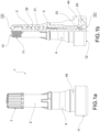
- the valve 1 substantially comprises a valve body 2, also referred to as an armature, an actuating mechanism 3 arranged inside said valve body 2, and a rubber ring 4 adapted to partially cover said valve body 2.
- the valve 1 comprises a head 11 arranged at a proximal end with respect to a rim at the installed position.
- a closing and protecting cap 7 is screwed to cover a distal opening 131 at the opposite end, referred to as the distal end 13.
- the distal end 13 of the valve 1 is insertable through a hole in the rim while the proximal end 12, and in particular the head 11 provided with a proximal opening 121, is intended to be engaged in said hole for fixing the valve in place on the rim.
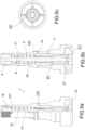
- the valve body 2 shown in detail in figures 3a and 3b , is cylindrical in shape, is axially hollow, and is adapted to connect the interior of a rubberized wheel to the outside environment and to allow air and a possible tire repair fluid to pass.
- valve body 2 is in one piece.
- the valve body 2 has an outer surface 20" with cylindrical symmetry and an inner surface 20' with cylindrical symmetry.
- valve body 2 is partially covered by a rubber ring 4 which acts as a sealing gasket when the valve 1 is mounted to the wheel.
- the valve body 2 extends into the rubber ring 4 over the entire longitudinal extension of the valve 1, i.e., up to the proximal end 12.
- the valve body 2 comprises a distal portion 23 which defines the distal end 13 of the valve 1, and a proximal portion 22 which at least partially defines the proximal end 12 of the valve 1.
- the distal portion 23 of the valve body 2 has, at the free end thereof, an outer thread 71 to receive the closing cap 7 and to be coupled to the inflation systems.
- the distal portion 23 comprises a circumferentially protruding backing element 25 just before the beginning of the proximal portion 22, and thus in a substantially central position of the valve body 2.
- the proximal portion 22 of the valve body 2 is adapted to be covered by the rubber ring 4, and thus to be embedded therein.
- the proximal portion 22 comprises, at the free end, a body head 24 circumferentially protruding from the valve body 2 and having the largest diameter of the whole remaining valve body 2.
- the body head 24 is fully embedded in the rubber ring 4, without axially protruding underneath it.
- the rubber ring 4 thus completely covers the proximal portion 22 of the valve body 2.
- the rubber ring 4 comprises a distal portion 43 and a proximal portion 42 which at least partially defines the proximal end 12 of the valve 1.
- the proximal portion 42 of the rubber ring 4 comprises, at the free end thereof, a circumferentially protruding ring head 44 having the largest diameter of the whole remaining rubber ring 4.
- the proximal portion 42 of the rubber ring 4 comprises, downstream of the ring head 44, an annular groove 45 adapted to accommodate the edge of the rim hole.
- the outer surface 20" of the valve body 2 intended to be covered by the rubber ring 4 comprises a plurality of annular ribs 6 to facilitate the retention of the rubber ring 4 on the valve body 2 and promote the pressure sealing. Indeed, in order to obtain the valve 1, the valve body 2 must be inserted into the rubber ring 4, so that the proximal portion 22 of the valve body 2 is completely covered by the rubber ring 4.
- valve body 2 The inner portion of the valve body 2, and in particular the inner surface 20' thereof shown in figure 3a , intended to cooperate with the actuating mechanism 3 for the tire inflation/deflation according to the present invention, will now be described in detail.
- the distal portion 23 of the valve body 2, in which an elastic thrust element 32 of the actuating mechanism 3 is housed, has a larger inner diameter than the inner diameter at the proximal portion 22.
- a preferably frustoconical sealing seat 221 is defined, in which a sealing ring 33 of the actuating mechanism 3 is housed.
- the valve sealing is obtained underneath the annular groove 45 and thus inside the tire.
- the preferably frustoconical sealing seat 221 in which a sealing ring 33 of the actuating mechanism 3 is housed, is positioned substantially in the center of the valve body 2.
- the valve sealing is obtained above the annular groove 45 and thus outside the tire.
- a shaped passageway 8 shown in figures 3b and 3c , is provided to allow selectively the axial sliding or axial locking of a pin 31 of the actuating mechanism 3.
- the shaped passageway 8 comprises a pair of locking teeth 81, which internally protrude and face each other.
- Each locking tooth 81 defines an upper abutment surface 832, facing the distal portion 23, and a lower abutment surface 831, facing the proximal portion 22.
- the upper abutment surface 832 provides an axial backing element for an elastic thrust element 32 of the actuating mechanism 3.
- the lower abutment surface 831 provides an axial backing element for a pin 31 of the actuating mechanism 3 during the opening step or for keeping the mechanism open.
- the shaped passageway 8 comprises, underneath the pair of locking teeth 81, in the direction of the proximal portion 22, at least one pair of body grooves 82 obtained on the inner surface 20'.
- body grooves 82 are provided evenly distributed along the inner circumference of the valve body 2.
- said body grooves 82 are axially offset with respect to the locking teeth 81. The presence of the body grooves 82 allows increasing the free space through the valve body 2, thus maximizing the flow of air through the valve 1 during the filling or discharging step.
- an actuating mechanism 3 for inflating/deflating the tire according to the present invention will now be described in detail.
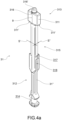
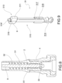
- Such an actuating mechanism 3 can be created in a long variant as in figure 4a and a short variant as in figure 9 .
- the sealing seat 221 of the valve body 2 is at the proximal end 12 and the pin 31 of the actuating mechanism 3 extends from the proximal end 12 to the distal end 13.
- the sealing seat 221 of the valve body 2 is retracted with respect to the proximal end 12 and the pin 31 of the actuating mechanism 3 extends from the proximal end 12 and ends before the distal end 13.
- the sealing seat 221 of the valve body 2 is arranged longitudinally above the annular groove 45 in which the tire rim is inserted.
- the actuating mechanism 3 comprises a pin 31 at a distal end of which an elastic element 32 is fitted, such as an axial spring, and a sealing ring 33 is arranged at an opposite proximal end.
- the pin 31 comprises a distal zone 313 provided with a gripping portion 316 which allows gripping the pin itself through the distal opening 131 of the valve 1, using a suitable tool described later.
- the gripping portion 316 is provided with an upper axial coupling protuberance 316' also adapted to guide and center the tool described below.
- the distal zone 313 is provided with a backing element 311 which defines at least one abutment surface 311' for the elastic thrust element 32.
- the pin 31 comprises a paddle-like portion 9 arranged at the distal zone 313, which forms the gripping portion 316 at the front and the backing element 311 and the abutment surfaces 311' thereof at the bottom.
- the pin 31 comprises a proximal zone 312 provided with a housing 314, such as an annular groove, in which the sealing ring 33 is snap-engageable.
- the pin body 315 is centrally provided with at least one locking housing 317 adapted to engage at least one locking tooth 81 of the shaped passageway 8 defined inside the valve body 2.
- the locking housing 317 is a hook-shaped or U-shaped protrusion arranged on a narrow side S" of the pin body 315.
- a pair of locking housings 317 is provided to obtain a bayonet coupling with the pair of locking teeth 81.
- the pin body 315 is provided with a pin groove 318, obtained on the outer pin surface 31".
- a pin groove 318 is provided in line underneath the two locking housings 317.
- the presence of the pin grooves 318 allows increasing the free space through the valve body 2, thus maximizing the flow of air through the valve 1 during the filling or discharging step.
- the presence of the pin grooves 318 allows avoiding an accumulation of plastic material when molding the valve body 2, which could compromise the geometry thereof due to phenomena such as suctions or deformations of the piece after molding.
- the elastic thrust element 32 When the actuating mechanism 3 is inserted into the valve body 2, as shown in figure 1b , the elastic thrust element 32 is fitted on the pin 31 and compressed between the backing element 311 of the pin itself and the upper abutment surface 832 of the locking teeth 81 of the shaped passageway 8 within the valve body 2. The elastic element 32 thus compressed applies a thrust to the pin 31 in the distal direction to press the sealing ring 33 of the actuating mechanism 3 against the sealing seat 221 within the valve body 2, to close the inner passageway of the valve 1, as shown in figure 5b .
- the opening of the valve 1 is achieved by pushing the pin 31 in the opposite direction with respect to the elastic element 32, i.e., in the proximal direction to move the sealing ring 33 away from the sealing seat 221 within the valve body 2, when opening the inner passageway of the valve 1, as shown in figure 6b .
- a pushing and rotating tool 6 for example, commonly used in tire shops, and depicted in figure 7 .
- a pushing and rotating tool 6 for example, commonly used in tire shops, and depicted in figure 7 .
- a pushing and rotating tool 6 for example, commonly used in tire shops, and depicted in figure 7 .
- Such a tool in the form of a screwdriver, comprises a cylindrical body 61 provided at one end with a handle 62 and at an opposite end with a U-shaped tip 63 provided with a cylindrical inner chamber 64 at the bottom of the U. Therefore, the pin 31 of the actuating mechanism 3 is designed such that the gripping portion 316 has a profile which is insertable into the shaped tip 63 of the tool 6, and that the upper protuberance 316' can be easily inserted into the inner chamber 64 of the tool 6.
- the valve 1 is a plastic valve provided with a valve body 2 totally made of plastic material, a rubber sealing ring 4, and an actuating mechanism 3 in which the pin 31 is totally made of plastic material, the sealing ring 33 is made of rubber, and the elastic element 32 is the only metal element.
- the elastic element 32 may be also totally made of plastic material.
- the rubber ring 4 is made of ethylene-propylene rubber, preferably EPDM (Ethylene-Propylene Diene Monomer).
- EPDM Ethylene-Propylene Diene Monomer
- the rubber ring 4 is made of 100% EPDM rubber.
- a valve 1 according to the present invention is found to be simple in construction and easy to assemble due to the particular actuating mechanism arranged within said valve body.
- valve 1 equipped with the particular actuating mechanism described above, the flow of air through the valve during the filling or discharging operations has been maximized.
- valve 1 equipped with the particular actuating mechanism described above, it is not necessary to maintain manually, or with special tools, the opening condition of the internal mechanism for as long as it is necessary to completely deflate the tire, thus simplifying the maintenance operations. Such operations also do not require the inner mechanism to be removed and then mounted back into the valve, as is the case with normally used valves, thus reducing the risk of contamination thereof.
- valve 1 equipped with the particular actuating mechanism described above, the inner inflation/deflation mechanism can be removed, thus making it entirely replaceable.
- the inner inflation/deflation mechanism can be easily removed allowing the recycling of the various valve components.
- both the pin 31 and the valve body 2 can be molded from plastic using uncomplex molds as no threads or undercuts are provided, for example.
Claims (12)
- Soupape (1) pour roues caoutchoutées, ayant une extrémité proximale (12) pour le raccordement à une roue caoutchoutée et une extrémité distale opposée (13), ladite soupape (1) comprenant :- un corps de soupape creux (2) de forme cylindrique, conçu pour raccorder l'intérieur de ladite roue caoutchoutée à l'environnement extérieur et permettre à l'air de passer, ledit corps de soupape (2) définissant en interne un siège d'étanchéité (221) ;- un mécanisme d'actionnement (3) de ladite soupape (1) agencé à l'intérieur du corps de soupape (2), et comprenant une tige (31) avec une zone distale (313) sur laquelle un élément élastique (32) est installé, et avec une zone proximale (312) sur laquelle une bague d'étanchéité (33) est agencée, conçu pour fermer hermétiquement le siège d'étanchéité (221) du corps de soupape (2) dans une configuration fermée dans laquelle l'air ne peut pas passer à travers ledit corps de soupape (2) ;- une bague en caoutchouc (4) conçue pour recouvrir partiellement le corps de soupape (2) ;caractérisée en ce que par application d'une poussée dans la direction proximale et d'une rotation sur la tige (31), au moins une dent de verrouillage (81) agencée à l'intérieur du corps de soupape (2) est insérée dans au moins un logement de verrouillage (317) agencé sur la tige (31), verrouillant ainsi ladite tige à l'intérieur du corps de soupape (2) dans une configuration d'ouverture dans laquelle la bague d'étanchéité (33) est séparée du siège d'étanchéité (221) pour permettre à l'air ou à des fluides de réparation de passer à travers ledit corps de soupape (2).
- Soupape (1) selon la revendication 1, dans laquelle :- le corps de soupape (2) est doté en interne d'un passage façonné (8) comprenant ladite au moins une dent de verrouillage (81) avec une surface de butée inférieure (831) qui fournit un élément d'appui axial à la tige (31) du mécanisme d'actionnement (3) ;- la tige (31) comprend ledit au moins un logement de verrouillage (317) conçu pour venir en prise avec ladite au moins une dent de verrouillage (81) du passage façonné (8).
- Soupape (1) selon la revendication 2, dans laquelle le logement de verrouillage (317) est en forme de crochet ou en forme de U pour former un couplage à baïonnette avec ladite au moins une dent de verrouillage (81) du corps de soupape (2).
- Soupape (1) selon l'une quelconque des revendications 2 à 3, dans laquelle le passage façonné (8) comprend, sous ladite au moins une dent de verrouillage (81), au moins une rainure de corps (82) décalée axialement par rapport à ladite dent de verrouillage (81), et/ou
dans laquelle la tige (31) comprend, sous ledit au moins un logement de verrouillage (317), au moins une rainure de tige (318) en adéquation avec ledit logement de verrouillage (317). - Soupape (1) selon l'une quelconque des revendications précédentes, dans laquelle :- le corps de soupape (2) est doté en interne d'un passage façonné (8) comprenant ladite au moins une dent de verrouillage (81) avec une surface de butée supérieure (832) qui fournit un élément d'appui inférieur à l'élément élastique (32) du mécanisme d'actionnement (3) ;- la tige (31) comprend au moins un élément d'appui (311) avec une surface de butée (311'), qui fournit un élément d'appui supérieur à l'élément élastique (32) du mécanisme d'actionnement (3).
- Soupape (1) selon l'une quelconque des revendications précédentes, dans laquelle la tige (31) comprend de manière distale une partie en forme de pale (9) qui forme une partie de préhension (316) à l'avant et un élément d'appui supérieur (311') à la partie inférieure pour l'élément élastique (32) du mécanisme d'actionnement (3).
- Soupape (1) selon l'une quelconque des revendications précédentes, dans laquelle la tige (31) comprend de manière proximale un logement (314), en forme de rainure annulaire, dans lequel la bague d'étanchéité (33) est mise en prise par encliquetage.
- Soupape (1) selon l'une quelconque des revendications précédentes, dans laquelle la tige (31) est dotée d'un corps de tige (315) ayant une section sensiblement polygonale.
- Soupape (1) selon l'une quelconque des revendications précédentes, dans laquelle à la fois le corps de soupape (2) et la tige (31) du mécanisme d'actionnement (3) sont en plastique, et la bague en caoutchouc (4) et la bague d'étanchéité (33) du mécanisme d'actionnement (3) sont en caoutchouc.
- Soupape (1) selon l'une quelconque des revendications précédentes, dans laquelle le siège d'étanchéité (221) du corps de soupape (2) se situe à l'extrémité proximale (12) et la tige (31) du mécanisme d'actionnement (3) s'étend de l'extrémité proximale (12) à l'extrémité distale (13).
- Soupape (1) selon l'une quelconque des revendications 1 à 9, dans laquelle le siège d'étanchéité (221) du corps de soupape (2) est rétracté par rapport à l'extrémité proximale (12), et la tige (31) du mécanisme d'actionnement (3) s'étend à partir de l'extrémité proximale (12) et prend fin avant l'extrémité distale (13).
- Soupape (1) selon la revendication 11, dans laquelle le siège d'étanchéité (221) est agencé longitudinalement au-dessus d'une rainure annulaire (45) de la bague en caoutchouc (4) destinée à recevoir une roue caoutchoutée.
Applications Claiming Priority (1)
| Application Number | Priority Date | Filing Date | Title |
|---|---|---|---|
| IT102021000005231A IT202100005231A1 (it) | 2021-03-05 | 2021-03-05 | Valvola per ruote gommate con nuovo meccanismo di azionamento |
Publications (3)
| Publication Number | Publication Date |
|---|---|
| EP4052934A1 EP4052934A1 (fr) | 2022-09-07 |
| EP4052934C0 EP4052934C0 (fr) | 2024-01-10 |
| EP4052934B1 true EP4052934B1 (fr) | 2024-01-10 |
Family
ID=76034957
Family Applications (1)
| Application Number | Title | Priority Date | Filing Date |
|---|---|---|---|
| EP22159421.1A Active EP4052934B1 (fr) | 2021-03-05 | 2022-03-01 | Soupape pour roues caoutchoutées avec un mécanisme d'actionnement |
Country Status (3)
| Country | Link |
|---|---|
| EP (1) | EP4052934B1 (fr) |
| CN (1) | CN115013569A (fr) |
| IT (1) | IT202100005231A1 (fr) |
Family Cites Families (7)
| Publication number | Priority date | Publication date | Assignee | Title |
|---|---|---|---|---|
| US3368603A (en) * | 1966-03-30 | 1968-02-13 | Scovill Manufacturing Co | Valve stem for tubeless tires and the like |
| US4171119A (en) | 1977-10-25 | 1979-10-16 | Lamson William C | Fluid flow valve stem |
| IT1153281B (it) * | 1982-10-21 | 1987-01-14 | Bridgeport Brass Spa | Parte interna migliorata per valvola atta ad essere applicata su articoli pneumatici |
| US6786131B2 (en) * | 2002-08-27 | 2004-09-07 | Lung-Po Tsai | Valve used for an inflatable article |
| CN204664516U (zh) * | 2015-05-27 | 2015-09-23 | 林志远 | 一种充气阀 |
| FR3066437B1 (fr) * | 2017-05-16 | 2021-04-09 | Schrader | Valve de gonflage pour pneu amelioree |
| WO2020194561A1 (fr) * | 2019-03-26 | 2020-10-01 | 太平洋工業株式会社 | Soupape |
-
2021
- 2021-03-05 IT IT102021000005231A patent/IT202100005231A1/it unknown
-
2022
- 2022-03-01 EP EP22159421.1A patent/EP4052934B1/fr active Active
- 2022-03-07 CN CN202210216955.5A patent/CN115013569A/zh active Pending
Also Published As
| Publication number | Publication date |
|---|---|
| EP4052934A1 (fr) | 2022-09-07 |
| EP4052934C0 (fr) | 2024-01-10 |
| CN115013569A (zh) | 2022-09-06 |
| IT202100005231A1 (it) | 2022-09-05 |
Similar Documents
| Publication | Publication Date | Title |
|---|---|---|
| US7686051B2 (en) | Central tire inflation wheel assembly and valve | |
| HU219783B (hu) | Vulkanizáló szerszám, és annak légtelenítő furatába való beépítésre szolgáló légtelenítőszelep | |
| EP2173532B1 (fr) | Soupape et procede de purge d'air d'un moule de vulcanisation | |
| US11904644B2 (en) | Inflation system for tubeless tires | |
| US6152165A (en) | Valve core mounting and dismounting tool | |
| EP3508360B1 (fr) | Ensemble soupape sans chambre à air | |
| EP4052934B1 (fr) | Soupape pour roues caoutchoutées avec un mécanisme d'actionnement | |
| US20240102573A1 (en) | Inflation valve for tubeless tires | |
| CN111670126B (zh) | 包括电子盒和可弹性变形类型的充气阀的用于测量车辆车轮的运行参数的电子单元 | |
| US5509438A (en) | Air valve adapter | |
| US3280879A (en) | Vehicle tire valve supporting means | |
| CA1094607A (fr) | Traduction non-disponible | |
| US7363953B2 (en) | Assembly formed of a tire and a sealing piece and manufacturing process | |
| US6119746A (en) | Valve and rim for bicycle wheel provided for a tubeless assembly | |
| US5060685A (en) | Safety cap for tire valve | |
| US3422836A (en) | Valve for dual chambered tires | |
| EP1388478B1 (fr) | Servomoteur d'assistance pneumatique au freinage et système comportant un maítre-cylindre solidarisé à un tel servomoteur | |
| US2908313A (en) | Pneumatic tire valve | |
| EP1033205A2 (fr) | Outil pour installer ou démonter des noyaux de valve | |
| CN115027187A (zh) | 用于橡胶轮的塑料嵌入式阀门 | |
| EP4311696A1 (fr) | Valve de gonflage de pneu et ensemble capteur de valve associé | |
| US2798530A (en) | Tubeless tire rim and valve | |
| US11867303B2 (en) | Nozzle adapter for Presta valve | |
| EP0015671A1 (fr) | Valve de pneumatique | |
| CN112984175A (zh) | 气门嘴和带有气门嘴的车轮 |
Legal Events
| Date | Code | Title | Description |
|---|---|---|---|
| PUAI | Public reference made under article 153(3) epc to a published international application that has entered the european phase |
Free format text: ORIGINAL CODE: 0009012 |
|
| STAA | Information on the status of an ep patent application or granted ep patent |
Free format text: STATUS: THE APPLICATION HAS BEEN PUBLISHED |
|
| AK | Designated contracting states |
Kind code of ref document: A1 Designated state(s): AL AT BE BG CH CY CZ DE DK EE ES FI FR GB GR HR HU IE IS IT LI LT LU LV MC MK MT NL NO PL PT RO RS SE SI SK SM TR |
|
| STAA | Information on the status of an ep patent application or granted ep patent |
Free format text: STATUS: REQUEST FOR EXAMINATION WAS MADE |
|
| 17P | Request for examination filed |
Effective date: 20221025 |
|
| RBV | Designated contracting states (corrected) |
Designated state(s): AL AT BE BG CH CY CZ DE DK EE ES FI FR GB GR HR HU IE IS IT LI LT LU LV MC MK MT NL NO PL PT RO RS SE SI SK SM TR |
|
| GRAP | Despatch of communication of intention to grant a patent |
Free format text: ORIGINAL CODE: EPIDOSNIGR1 |
|
| STAA | Information on the status of an ep patent application or granted ep patent |
Free format text: STATUS: GRANT OF PATENT IS INTENDED |
|
| INTG | Intention to grant announced |
Effective date: 20231004 |
|
| GRAS | Grant fee paid |
Free format text: ORIGINAL CODE: EPIDOSNIGR3 |
|
| GRAA | (expected) grant |
Free format text: ORIGINAL CODE: 0009210 |
|
| STAA | Information on the status of an ep patent application or granted ep patent |
Free format text: STATUS: THE PATENT HAS BEEN GRANTED |
|
| AK | Designated contracting states |
Kind code of ref document: B1 Designated state(s): AL AT BE BG CH CY CZ DE DK EE ES FI FR GB GR HR HU IE IS IT LI LT LU LV MC MK MT NL NO PL PT RO RS SE SI SK SM TR |
|
| REG | Reference to a national code |
Ref country code: GB Ref legal event code: FG4D |
|
| REG | Reference to a national code |
Ref country code: CH Ref legal event code: EP |
|
| REG | Reference to a national code |
Ref country code: DE Ref legal event code: R096 Ref document number: 602022001568 Country of ref document: DE |
|
| REG | Reference to a national code |
Ref country code: IE Ref legal event code: FG4D |
|
| U01 | Request for unitary effect filed |
Effective date: 20240118 |
|
| U07 | Unitary effect registered |
Designated state(s): AT BE BG DE DK EE FI FR IT LT LU LV MT NL PT SE SI Effective date: 20240125 |
|
| U20 | Renewal fee paid [unitary effect] |
Year of fee payment: 3 Effective date: 20240222 |