EP4052883A1 - Method for manufacturing a clock component - Google Patents
Method for manufacturing a clock component Download PDFInfo
- Publication number
- EP4052883A1 EP4052883A1 EP21160550.6A EP21160550A EP4052883A1 EP 4052883 A1 EP4052883 A1 EP 4052883A1 EP 21160550 A EP21160550 A EP 21160550A EP 4052883 A1 EP4052883 A1 EP 4052883A1
- Authority
- EP
- European Patent Office
- Prior art keywords
- structured
- manufacturing
- component
- insert
- model element
- Prior art date
- Legal status (The legal status is an assumption and is not a legal conclusion. Google has not performed a legal analysis and makes no representation as to the accuracy of the status listed.)
- Pending
Links
Images


Classifications
-
- B—PERFORMING OPERATIONS; TRANSPORTING
- B29—WORKING OF PLASTICS; WORKING OF SUBSTANCES IN A PLASTIC STATE IN GENERAL
- B29C—SHAPING OR JOINING OF PLASTICS; SHAPING OF MATERIAL IN A PLASTIC STATE, NOT OTHERWISE PROVIDED FOR; AFTER-TREATMENT OF THE SHAPED PRODUCTS, e.g. REPAIRING
- B29C45/00—Injection moulding, i.e. forcing the required volume of moulding material through a nozzle into a closed mould; Apparatus therefor
- B29C45/17—Component parts, details or accessories; Auxiliary operations
- B29C45/26—Moulds
- B29C45/37—Mould cavity walls, i.e. the inner surface forming the mould cavity, e.g. linings
- B29C45/372—Mould cavity walls, i.e. the inner surface forming the mould cavity, e.g. linings provided with means for marking or patterning, e.g. numbering articles
-
- B—PERFORMING OPERATIONS; TRANSPORTING
- B29—WORKING OF PLASTICS; WORKING OF SUBSTANCES IN A PLASTIC STATE IN GENERAL
- B29B—PREPARATION OR PRETREATMENT OF THE MATERIAL TO BE SHAPED; MAKING GRANULES OR PREFORMS; RECOVERY OF PLASTICS OR OTHER CONSTITUENTS OF WASTE MATERIAL CONTAINING PLASTICS
- B29B11/00—Making preforms
- B29B11/06—Making preforms by moulding the material
-
- B—PERFORMING OPERATIONS; TRANSPORTING
- B29—WORKING OF PLASTICS; WORKING OF SUBSTANCES IN A PLASTIC STATE IN GENERAL
- B29C—SHAPING OR JOINING OF PLASTICS; SHAPING OF MATERIAL IN A PLASTIC STATE, NOT OTHERWISE PROVIDED FOR; AFTER-TREATMENT OF THE SHAPED PRODUCTS, e.g. REPAIRING
- B29C41/00—Shaping by coating a mould, core or other substrate, i.e. by depositing material and stripping-off the shaped article; Apparatus therefor
- B29C41/02—Shaping by coating a mould, core or other substrate, i.e. by depositing material and stripping-off the shaped article; Apparatus therefor for making articles of definite length, i.e. discrete articles
- B29C41/12—Spreading-out the material on a substrate, e.g. on the surface of a liquid
-
- A—HUMAN NECESSITIES
- A44—HABERDASHERY; JEWELLERY
- A44C—PERSONAL ADORNMENTS, e.g. JEWELLERY; COINS
- A44C27/00—Making jewellery or other personal adornments
- A44C27/001—Materials for manufacturing jewellery
-
- A—HUMAN NECESSITIES
- A44—HABERDASHERY; JEWELLERY
- A44C—PERSONAL ADORNMENTS, e.g. JEWELLERY; COINS
- A44C5/00—Bracelets; Wrist-watch straps; Fastenings for bracelets or wrist-watch straps
- A44C5/0053—Flexible straps
-
- A—HUMAN NECESSITIES
- A44—HABERDASHERY; JEWELLERY
- A44C—PERSONAL ADORNMENTS, e.g. JEWELLERY; COINS
- A44C5/00—Bracelets; Wrist-watch straps; Fastenings for bracelets or wrist-watch straps
- A44C5/0053—Flexible straps
- A44C5/0069—Flexible straps extensible
-
- B—PERFORMING OPERATIONS; TRANSPORTING
- B29—WORKING OF PLASTICS; WORKING OF SUBSTANCES IN A PLASTIC STATE IN GENERAL
- B29C—SHAPING OR JOINING OF PLASTICS; SHAPING OF MATERIAL IN A PLASTIC STATE, NOT OTHERWISE PROVIDED FOR; AFTER-TREATMENT OF THE SHAPED PRODUCTS, e.g. REPAIRING
- B29C41/00—Shaping by coating a mould, core or other substrate, i.e. by depositing material and stripping-off the shaped article; Apparatus therefor
- B29C41/02—Shaping by coating a mould, core or other substrate, i.e. by depositing material and stripping-off the shaped article; Apparatus therefor for making articles of definite length, i.e. discrete articles
-
- B—PERFORMING OPERATIONS; TRANSPORTING
- B29—WORKING OF PLASTICS; WORKING OF SUBSTANCES IN A PLASTIC STATE IN GENERAL
- B29C—SHAPING OR JOINING OF PLASTICS; SHAPING OF MATERIAL IN A PLASTIC STATE, NOT OTHERWISE PROVIDED FOR; AFTER-TREATMENT OF THE SHAPED PRODUCTS, e.g. REPAIRING
- B29C41/00—Shaping by coating a mould, core or other substrate, i.e. by depositing material and stripping-off the shaped article; Apparatus therefor
- B29C41/34—Component parts, details or accessories; Auxiliary operations
- B29C41/38—Moulds, cores or other substrates
-
- B—PERFORMING OPERATIONS; TRANSPORTING
- B29—WORKING OF PLASTICS; WORKING OF SUBSTANCES IN A PLASTIC STATE IN GENERAL
- B29C—SHAPING OR JOINING OF PLASTICS; SHAPING OF MATERIAL IN A PLASTIC STATE, NOT OTHERWISE PROVIDED FOR; AFTER-TREATMENT OF THE SHAPED PRODUCTS, e.g. REPAIRING
- B29C45/00—Injection moulding, i.e. forcing the required volume of moulding material through a nozzle into a closed mould; Apparatus therefor
- B29C45/14—Injection moulding, i.e. forcing the required volume of moulding material through a nozzle into a closed mould; Apparatus therefor incorporating preformed parts or layers, e.g. injection moulding around inserts or for coating articles
-
- B—PERFORMING OPERATIONS; TRANSPORTING
- B29—WORKING OF PLASTICS; WORKING OF SUBSTANCES IN A PLASTIC STATE IN GENERAL
- B29C—SHAPING OR JOINING OF PLASTICS; SHAPING OF MATERIAL IN A PLASTIC STATE, NOT OTHERWISE PROVIDED FOR; AFTER-TREATMENT OF THE SHAPED PRODUCTS, e.g. REPAIRING
- B29C45/00—Injection moulding, i.e. forcing the required volume of moulding material through a nozzle into a closed mould; Apparatus therefor
- B29C45/17—Component parts, details or accessories; Auxiliary operations
- B29C45/26—Moulds
- B29C45/2673—Moulds with exchangeable mould parts, e.g. cassette moulds
-
- G—PHYSICS
- G04—HOROLOGY
- G04B—MECHANICALLY-DRIVEN CLOCKS OR WATCHES; MECHANICAL PARTS OF CLOCKS OR WATCHES IN GENERAL; TIME PIECES USING THE POSITION OF THE SUN, MOON OR STARS
- G04B45/00—Time pieces of which the indicating means or cases provoke special effects, e.g. aesthetic effects
- G04B45/0076—Decoration of the case and of parts thereof, e.g. as a method of manufacture thereof
-
- B—PERFORMING OPERATIONS; TRANSPORTING
- B29—WORKING OF PLASTICS; WORKING OF SUBSTANCES IN A PLASTIC STATE IN GENERAL
- B29C—SHAPING OR JOINING OF PLASTICS; SHAPING OF MATERIAL IN A PLASTIC STATE, NOT OTHERWISE PROVIDED FOR; AFTER-TREATMENT OF THE SHAPED PRODUCTS, e.g. REPAIRING
- B29C45/00—Injection moulding, i.e. forcing the required volume of moulding material through a nozzle into a closed mould; Apparatus therefor
- B29C45/14—Injection moulding, i.e. forcing the required volume of moulding material through a nozzle into a closed mould; Apparatus therefor incorporating preformed parts or layers, e.g. injection moulding around inserts or for coating articles
- B29C45/14754—Injection moulding, i.e. forcing the required volume of moulding material through a nozzle into a closed mould; Apparatus therefor incorporating preformed parts or layers, e.g. injection moulding around inserts or for coating articles being in movable or releasable engagement with the coating, e.g. bearing assemblies
- B29C2045/1477—Removable inserts, e.g. the insert being peeled off after moulding
-
- B—PERFORMING OPERATIONS; TRANSPORTING
- B29—WORKING OF PLASTICS; WORKING OF SUBSTANCES IN A PLASTIC STATE IN GENERAL
- B29C—SHAPING OR JOINING OF PLASTICS; SHAPING OF MATERIAL IN A PLASTIC STATE, NOT OTHERWISE PROVIDED FOR; AFTER-TREATMENT OF THE SHAPED PRODUCTS, e.g. REPAIRING
- B29C33/00—Moulds or cores; Details thereof or accessories therefor
- B29C33/0011—Moulds or cores; Details thereof or accessories therefor thin-walled moulds
- B29C33/0016—Lost moulds, e.g. staying on the moulded object
-
- B—PERFORMING OPERATIONS; TRANSPORTING
- B29—WORKING OF PLASTICS; WORKING OF SUBSTANCES IN A PLASTIC STATE IN GENERAL
- B29C—SHAPING OR JOINING OF PLASTICS; SHAPING OF MATERIAL IN A PLASTIC STATE, NOT OTHERWISE PROVIDED FOR; AFTER-TREATMENT OF THE SHAPED PRODUCTS, e.g. REPAIRING
- B29C39/00—Shaping by casting, i.e. introducing the moulding material into a mould or between confining surfaces without significant moulding pressure; Apparatus therefor
- B29C39/02—Shaping by casting, i.e. introducing the moulding material into a mould or between confining surfaces without significant moulding pressure; Apparatus therefor for making articles of definite length, i.e. discrete articles
- B29C39/026—Shaping by casting, i.e. introducing the moulding material into a mould or between confining surfaces without significant moulding pressure; Apparatus therefor for making articles of definite length, i.e. discrete articles characterised by the shape of the surface
-
- B—PERFORMING OPERATIONS; TRANSPORTING
- B29—WORKING OF PLASTICS; WORKING OF SUBSTANCES IN A PLASTIC STATE IN GENERAL
- B29K—INDEXING SCHEME ASSOCIATED WITH SUBCLASSES B29B, B29C OR B29D, RELATING TO MOULDING MATERIALS OR TO MATERIALS FOR MOULDS, REINFORCEMENTS, FILLERS OR PREFORMED PARTS, e.g. INSERTS
- B29K2021/00—Use of unspecified rubbers as moulding material
-
- B—PERFORMING OPERATIONS; TRANSPORTING
- B29—WORKING OF PLASTICS; WORKING OF SUBSTANCES IN A PLASTIC STATE IN GENERAL
- B29K—INDEXING SCHEME ASSOCIATED WITH SUBCLASSES B29B, B29C OR B29D, RELATING TO MOULDING MATERIALS OR TO MATERIALS FOR MOULDS, REINFORCEMENTS, FILLERS OR PREFORMED PARTS, e.g. INSERTS
- B29K2083/00—Use of polymers having silicon, with or without sulfur, nitrogen, oxygen, or carbon only, in the main chain, as moulding material
-
- B—PERFORMING OPERATIONS; TRANSPORTING
- B29—WORKING OF PLASTICS; WORKING OF SUBSTANCES IN A PLASTIC STATE IN GENERAL
- B29L—INDEXING SCHEME ASSOCIATED WITH SUBCLASS B29C, RELATING TO PARTICULAR ARTICLES
- B29L2029/00—Belts or bands
-
- B—PERFORMING OPERATIONS; TRANSPORTING
- B29—WORKING OF PLASTICS; WORKING OF SUBSTANCES IN A PLASTIC STATE IN GENERAL
- B29L—INDEXING SCHEME ASSOCIATED WITH SUBCLASS B29C, RELATING TO PARTICULAR ARTICLES
- B29L2031/00—Other particular articles
- B29L2031/727—Fastening elements
- B29L2031/7276—Straps or the like
-
- B—PERFORMING OPERATIONS; TRANSPORTING
- B29—WORKING OF PLASTICS; WORKING OF SUBSTANCES IN A PLASTIC STATE IN GENERAL
- B29L—INDEXING SCHEME ASSOCIATED WITH SUBCLASS B29C, RELATING TO PARTICULAR ARTICLES
- B29L2031/00—Other particular articles
- B29L2031/743—Jewellery
Definitions
- the present invention relates to a method for manufacturing a structured insert for a mold for manufacturing a watch or jewelry component. It also relates to a process for manufacturing a watch or jewelry component which uses such a structured insert. It also relates to a watch component as such, in particular a bracelet strand, particularly an elastomer bracelet strand, obtained by such a process.
- Another complementary approach consists in modifying the appearance of the surface of the bracelet strand after it comes out of a mold, by one or more additional finishing steps, for example by a calendering step. Such an approach likewise complicates the method by adding one or more additional steps. Moreover, it does not make it possible to form all types of textures.
- the object of the present invention is to improve the known methods of manufacturing a watchmaking or jewelry component, and in particular to achieve all or part of the following objects.
- the first object of the invention is to be able to manufacture a watch or jewelry component having a defined technical functionality, in particular a hydrophilic or hydrophobic character, and/or having an attractive aesthetic appearance, in particular having a structured surface with a chosen pattern.
- a second object of the invention is to be able to manufacture a watch or jewelry component comprising a structured elastomer surface.
- a third object of the invention is to be able to manufacture a watch or jewelry component comprising a structured surface of complex shape.
- a fourth object of the invention is to be able to manufacture a watch or jewelry component comprising a structured surface suitable for small production runs, in particular with the aim of being able to easily change the pattern of the structured surface of the watch component to be manufactured.
- the invention also relates to an assembly comprising a model element and such a horological component, characterized in that the horological component comprises a structured surface which reproduces a structured surface of the model element with a resolution less than or equal to 1 ⁇ m, or even less than or equal to 100 nm, or even less than or equal to 10 nm, or even less than or equal to 1 nm.
- the invention achieves the desired objects by the intermediate manufacture of a structured insert, intended to be inserted into a mold for manufacturing a timepiece or jewelry component to form a structured surface of the timepiece component which is manufactured in such a mold.
- the method for manufacturing a watch component comprises a first phase of manufacturing a structured insert for a mold for manufacturing a watch component, represented schematically by the figure 1 .
- the method comprises a first step consisting in providing E1 with a model element 50 comprising a structured surface 51 with a pattern to be reproduced.
- the pattern of the structured surface of this model element is called "master pattern”: it is an existing pattern that one wishes to reproduce in an identical manner, with very high precision, on a surface of a bracelet strand .
- the model element can also be called by its English name of “master”.
- structured surface is meant a surface which has reliefs, positive and/or negative, that is to say projecting or recessed relative to said surface. These reliefs form a master pattern of the structured surface.
- this structured surface may or may not be flat, for example curved.
- the method according to the invention advantageously makes it possible to reproduce a wide variety of master patterns, including complex patterns and/or patterns involving very small dimensions, in particular micrometric, or even nanometric. Naturally, the invention does not relate to the master pattern as such, which can be arbitrary.
- the master pattern may be a natural pattern, such as that present on the surface of animal skin, leather, alligator skin, bark, leaf, microcrystals, in particular silicon carbide crystals or ruthenium crystals, etc.
- it may be unnatural, artificial, and produced on a substrate by any known technique such as traditional machining, laser engraving, etc.
- It can for example be formed by a metal textured by abrasion, in particular by forming a sunburst or any other form of satin-finishing, by traditional etching, by laser or by electrochemistry, or by a wafer having electroformed decorations obtained by deposition of a metal in the cavities of a photopolymerized photosensitive resin, or by a surface of a silicon wafer, or by a weaving of fibers, etc.
- the master pattern can be complex.
- it may comprise hollow portions forming cavities of complex shape, in particular having an opening narrower than its width or more widely comprising a lower section parallel to the structured surface with a larger area than another section. parallel superimposed above the lower section, that is to say have a shape such that it presents a bottleneck during the demolding of the cavity.
- the figures 2a to 2d illustrate examples of complex cavities seen in section, in a plane perpendicular to the structured surface 51 of a model element, which structured surface 51 thus comprises at least one such complex cavity 52, or even a multitude of complex, identical or different cavities.
- a complex cavity 52 comprises an opening 53 opening onto the structured surface 51, then extends into the depth of the model element.
- This complex cavity 52 comprises at least one section, as shown in these figures, such that the greatest width L of this section in a plane parallel to the structured surface 51 is greater than the width I of the opening 53.
- a complex cavity can comprise a first section parallel to the structured surface 51 of the model element of greater area than a second superimposed parallel section positioned above this first parallel section, that is to say more close to the opening 53.
- the complexity can also come from a very large number of reliefs, projecting and/or hollow, which can be juxtaposed or intersect.
- the complexity may come from the resolution of the master pattern, which may involve very small dimensions.
- the structured surface 51 of the model element can comprise at least one relief of height H, measured in the direction perpendicular to the structured surface 51, comprised between 1 nm and 2 mm, or even between 1 nm and 500 ⁇ m, even between 1 nm and 10 ⁇ m, even between 1 nm and 10 nm.
- the method then comprises a second step consisting in covering E2 said structured surface of the model element 50 with a molding resin, capable of reproducing a negative pattern of said master pattern of the model element, after solidification of the molding resin, to obtain a structured insert 10.
- the molding resin has a viscosity before solidification at ambient temperature and pressure of between 0.5 and 70,000 Pa.s -1 , or even between 0.5 and 30,000 Pa.s -1 , or even between 0.5 and 1,000 Pa.s -1 .
- a viscosity before solidification at ambient temperature and pressure favors its infiltration into cavities, including complex cavities, of the structured surface of the model element 50. It thus penetrates into the smallest recesses of the structured surface of the model element 50, to reproduce with a very great precision the shape of this structured surface. As it solidifies, all the details of the surface on which the molding resin has been applied are reproduced very precisely.
- the precision of the reproduction can be of the order of a micrometer, or even of the order of a nanometer.
- the molding resin comprises polyurethane, latex, acrylic resin, fluoroelastomer such as FKM, PDMS (PolyDimethylSiloxane), an epoxy resin, or two-component silicone, in particular two-component vulcanizing by addition, in particular of the family of vinyl-polydimethyl-siloxanes, or in particular comprising vinyl, silicic acid and aggregation materials.
- the molding resin may further comprise one or more additives selected from an adjuvant, an aggregation material, and a colorant.
- a more viscous resin or even a pasty or solid material, such as raw fluorocarbon rubber (FKM)
- FKM raw fluorocarbon rubber
- the molding resin forms a structured insert 10.
- this structured insert 10 is flexible.
- its flexibility is adapted to its release from the model element 50, in particular in the case where this model element comprises a pattern with complex cavities.
- the molding resin exhibits little or even zero shrinkage, in order to faithfully reproduce and preserve the characteristics of the pattern to be reproduced.
- the shrinkage is less than or equal to 2 ⁇ , or even less than or equal to 1 ⁇ .
- the molding resin is chosen so as to achieve, once solidified, a flexibility compatible with the extraction stress, calculated using the following formula: 1 ⁇ Minimum dimension of the ′ orifice d ′ extraction Maximum internal dimension
- Constraint d ′ Extraction in %
- the molding resin is chosen so as to form a structured insert 10 which can be separated from the model element without damaging the model element or the structured insert.
- the solidification of the molding resin corresponds to its polymerization. It consists of two steps: setting the resin, following which the resin is dry to the touch, then curing the resin, following which the final mechanical properties of the resin are achieved.
- the polymerization kinetics of the molding resin for impression taking is generally rapid.
- the polymerization time at room temperature can be between 1 and 30 minutes, preferably between 1 and 15 minutes.
- the setting time at ambient temperature (20° C.) is between 15 and 90 seconds.
- the hardening time is between 1 and 10 minutes.
- this silicone as molding resin is particularly advantageous: its solidification time is short and this silicone can be implemented with a very simple installation.
- the method then comprises a third step consisting in separating E3 the structured insert 10 from the model element 50, this structured insert 10 comprising a structured surface 11 reproducing the master pattern in negative.
- the solidified molding resin retains a flexibility which allows it easy demolding of the model element 50, without deterioration of the pattern of the structured surface 11.
- the structured insert 10 thus comprises a structured surface 11, which corresponds to the identical negative reproduction of the structured surface 51 of the model element 50.
- the model element is preferably cleaned before the application of the molding resin to present a receiving surface, comprising the surface structured to reproduce, perfectly clean when applying the molding resin.
- this surface can also be coated with a release agent.
- the structured insert is resistant to compression while remaining quite flexible, which results in a hardness of between 20 and 90 Shore A, or even between 20 and 40 Shore A or between 50 and 70 Shore A or between 80 and 90 Shore A.
- this resistance combined with the flexibility of the insert, is adapted to the model element used.
- the structured insert 10 obtained is sufficiently flexible to be able to match the possibly non-planar shape of the surface of the mold on which it is intended to be positioned, as will be detailed below.
- the apparent modulus of the structured insert 10 for a deformation of 100% is advantageously less than 300 MPa, or even less than 50 MPa, or even less than 10 MPa.
- the resistance to tearing without a notch according to standard ISO 34-1 B(a) of the structured insert 10 is preferably greater than or greater than 5, or even greater than 10.
- the structured insert 10 is directly obtained.
- the method comprises an additional step of cutting the molding resin separated from the model element to form the structured insert in its final format.
- the method may comprise an optional additional step of depositing a coating of a mold release agent on the structured insert 10, in particular by coating, by chemical vapor deposition (CVD), by deposition physical vapor phase (PVD), by atomic layer deposition (ALD), by sol-gel deposition, by SAM (Self Assembled Monolayer) deposition, or by depositing a fluorinated coating on the structured insert, for example in a material from polytetrafluoroethylene (PTFE), fluorinated ethylene propylene (FEP), or perfluoroalkoxy (PFA).
- CVD chemical vapor deposition
- PVD physical vapor phase
- ALD atomic layer deposition
- sol-gel deposition by SAM (Self Assembled Monolayer) deposition
- fluorinated coating for example in a material from polytetrafluoroethylene (PTFE), fluorinated ethylene propylene (FEP), or perfluoroalkoxy (PFA).
- PTFE polyte
- the method of manufacturing a watch component then comprises a second phase of manufacturing a watch component as such, represented by the figures 3a to 3c , which uses the structured insert 10 manufactured by the method for manufacturing the structured insert described previously, which therefore forms the first phase of the method for manufacturing a timepiece component.
- This method comprises a fourth step consisting in positioning E4 the structured insert 10 in a mold 1 for manufacturing a watch component, in particular a metal mold, for example made of steel, as shown in picture 3a .
- this positioning is achieved by simple insertion into a housing provided for this purpose in the mould, in a sufficiently adjusted manner to induce maintenance of the structured insert 10. The latter is therefore advantageously maintained in the mold without gluing or fixing.
- This mold housing is in the form of a cavity whose shape and thickness correspond to those of the structured insert.
- the structured insert 10 can have any shape, and occupy all or part of the mold surface. In addition, it has sufficient flexibility to perfectly match the shape of the housing provided to receive it, without leaving any gaps. Its material also allows it not to adhere to the mould. It can thus be demoulded easily, without the need to add a demoulding agent to the surface of the mould.
- the structured insert 10 can be manufactured in the first phase according to a shape at rest (corresponding to that of the model element) which corresponds to that of the housing of the mold, so that it will be perfectly adapted to this housing with no need (or little) to deform it.
- the method then comprises a step consisting in filling E5 the manufacturing mold 1 including the structured insert 10 with a material of the component, as represented by the figure 3b , including filling in the negative pattern of the structured surface of the structured insert 10, then letting the material of the component solidify to obtain a blank 20 of the timepiece component comprising a structured surface comprising the identical reproduction of the master pattern of the model element.
- the material of the component is an elastomer or based on an elastomer, that is to say comprising at least 50% by weight of elastomer.
- the elastomer material can be a fluoroelastomer (FKM, FFKM or FEPM), or a natural (NR) or synthetic (SBR, HNBR, EPDM) rubber.
- the material of the component is a polymer, thermoplastic or thermoset, provided that the geometry of the structure makes it possible to separate the insert from the component without degrading the latter.
- the choice of component material is such that it is adapted to a more or less complex specific shape of the timepiece component to be manufactured, the most complex shapes requiring the use of a component material with the most efficient mechanical properties.
- the timepiece component is thus advantageously flexible.
- it may have a non-planar shape at rest, induced by the shape of the manufacturing mold.
- This shape is advantageously curved or arcuate, in particular concave or convex.
- the timepiece component can be rigid at rest, that is to say retain a predefined shape at rest, which can advantageously be modified by elastic deformation, in particular in the case of a bracelet, due to the flexible material used.
- the resin for molding the structured insert is naturally chosen to be compatible with the filling conditions in the mold 1 of the material of the component.
- the structured insert resists the vulcanization conditions of the elastomer forming the timepiece component. For this, it withstands temperatures of 160° C., or even up to 180° C., or even up to 250° C., for at least 15 minutes and preferably for several hours. At these temperatures, the structured insert additionally withstands pressures of between 80 bar and 150 bar, or even between 80 bar and 90 bar, without deformation.
- the structured insert for example, advantageously withstands several cycles of vulcanization of an elastomer, from 5 to 15 minutes each.
- the step consisting in filling E5 the manufacturing mold therefore advantageously comprises casting or injecting the material of the component, and makes it possible to form a timepiece component comprising a structured surface in one piece.
- the method then comprises a step consisting in removing E6 the blank 20 of the timepiece component from the mould.
- the structured insert 10 remains secured to said blank 20, due to their interlocking at the level of the structured surface, and due to the fact that there is no attachment of the insert. structured on the manufacturing mould, as represented by the figure 3c .
- the structured insert 10 fulfills a second function of protecting the structured surface of the blank 20 of the timepiece component.
- This blank 20 can indeed undergo one or more other steps consisting in finishing E7 the component, optional, such as for example deburring, sanding, marking, and/or decoration, etc., during which its structured surface remains perfectly intact. thanks to the protection of the structured insert 10.
- the method then comprises a step consisting in separating E8 the blank 20 of the timepiece component from the structured insert 10 to obtain the timepiece component.
- the structured insert 10 can be separated from the blank 20 during the step consisting in removing E6 the blank 20 from the mold 1. This structured insert 10 can be reused within the mold to manufacture a new blank and another identical watch component.
- the invention also relates to a structured insert for a mold for manufacturing a watch component, characterized in that it is made of resin and comprises a structured surface comprising a negative pattern of a pattern to be reproduced on a watch component.
- This structured insert can be flexible, with an apparent modulus for a deformation of 100% less than or equal to 300 MPa, or even less than or equal to 50 MPa, or even less than or equal to 10 MPa.
- It can have a hardness between 20 and 90 Shore A, or even between 20 and 40 Shore A or between 50 and 70 Shore A or between 80 and 90 Shore A. Its tear strength without notch can be greater than or equal to 5, or even greater than or equal to 10.
- It can withstand a temperature of 160°C, or even a temperature of 180°C, or even a temperature of 250°C, for at least 15 minutes or even at least one or two hours. It can withstand these temperatures without deformation at a maximum pressure of between 80 bar and 150 bar.
- the structured insert can be for single use or used for the manufacture of a small number of watch components, for example up to 50 watch components.
- the invention also relates to a watch or jewelry component as such obtained by the process according to the invention.
- a horological component can be a bracelet.
- it can be any exterior component of a wristwatch, such as a watch bezel or a middle part.
- Such a timepiece component therefore has a structured surface, defining a pattern which may be complex.
- This pattern can for example comprise at least one cavity whose opening is narrower than the width or comprising a lower section of larger area than another section superimposed above the lower section. It may comprise at least one height relief, measured in the direction perpendicular to said structured surface, of between 1 nm and 2 mm, or even between 1 nm and 500 ⁇ m, or even between 1 nm and 10 ⁇ m, or even between 1 nm and 10 n.
- the timepiece component can be wholly or partly in one piece, or even in one piece.
- the watch component may include one or more inserts such as a reinforcing blade as described in the document EP2783592A1 .
- the structured surface may comprise several intersecting reliefs.
- the invention also relates to a wristwatch comprising at least one horological component as described above.
- the invention also relates to an assembly comprising a model element and a horological component, which comprises a structured surface which reproduces a structured surface of the model element with a resolution less than or equal to 1 ⁇ m, or even less than or equal to 100 nm, or even less than or equal to 10 nm, or even less than or equal to 1 nm.
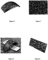
- the chosen "master" pattern is formed by silicon carbide crystals, for example formed from an upper surface of a silicon carbide washer as represented by the figure 4 , which thus represents the chosen model element.
- the figure 5 represents an enlarged view of this upper surface, making it possible to visualize its texture.
- the structured surface considered extends in a plane. It is cleaned and degreased, then dried.
- a two-component silicone, containing vinyl, silicic acid and aggregation materials, is used to make the structured insert. This material may be that known by its trade name Plastiform TM F50 or Plastiform TM F85.
- the two silicone components are mixed in a dosing gun, which allows the mixture to be deposited on part of the structured surface of the model element, i.e.
- the structured insert does not comprise a fixed shape at rest, it is flexible enough to match the shape of a support on which it is positioned.
- the structured insert has a maximum thickness comprised between 0.2 mm and 2 mm, or even between 0.2 mm and 1 mm. The insert is then placed in a bracelet strand injection mold. It perfectly fits the curved housing made in the mold to receive it.
- An elastomer material preferably a fluorinated elastomer (FKM)
- FKM fluorinated elastomer
- Vulcanization at 180° C. is then carried out in 15 minutes, then the mold is cooled, opened, and the blank obtained by this injection is removed.
- the structured insert is retained on the structured surface of this bracelet blank, to serve as protection for subsequent manufacturing steps, in particular deburring or sandblasting.
- a wristwatch bracelet strand is formed, comprising a structured surface faithfully reproducing the master patterns of the upper surface of the silicon carbide washer.
- Such patterns could not be obtained through conventional mold machining.
- the figure 6 shows a perspective view from above of the manufactured bracelet strand, the upper surface of which is structured, identically reproducing the pattern of the upper surface of part of the silicon carbide washer.
- the figure 7 represents an enlarged view of this structured surface of the bracelet, making it possible to clearly distinguish its pattern.
- the model element is an alligator skin, which makes it possible to obtain a bracelet strand made of elastomeric material as represented by the figure 8 .
- the model element is a metal plate, one surface of which is engraved, represented by the figure 9 .
Abstract
Procédé de fabrication d'un insert structuré (10) pour un moule de fabrication d'un composant horloger ou de joaillerie, notamment pour la fabrication d'un brin de bracelet, caractérisé en ce qu'il comprend les étapes suivantes :∘ Se munir (E1) d'un élément modèle (50) comprenant une surface structurée (51) avec un motif à reproduire sur une surface d'un composant horloger;∘ Recouvrir (E2) ladite surface structurée (51) de l'élément modèle (50) avec une résine de moulage apte à reproduire un motif en négatif dudit motif de la surface structurée, et laisser solidifier la résine de moulage pour obtenir un insert structuré (10);∘ Séparer (E3) l'insert structuré (10) de l'élément modèle (50), cet insert structuré (10) comprenant une surface comprenant ledit motif en négatif;∘ Optionnellement, découper l'insert structuré (10) au format correspondant à au moins une partie du composant horloger à fabriquer.Process for manufacturing a structured insert (10) for a mold for manufacturing a watch or jewelery component, in particular for manufacturing a bracelet strand, characterized in that it comprises the following steps: (E1) of a model element (50) comprising a structured surface (51) with a pattern to be reproduced on a surface of a timepiece component;∘ Covering (E2) said structured surface (51) of the model element (50 ) with a molding resin capable of reproducing a negative pattern of said pattern of the structured surface, and letting the molding resin solidify to obtain a structured insert (10);∘ Separating (E3) the structured insert (10) from the model element (50), this structured insert (10) comprising a surface comprising said negative pattern; ∘ Optionally, cutting the structured insert (10) to the format corresponding to at least part of the timepiece component to be manufactured.
Description
La présente invention concerne un procédé de fabrication d'un insert structuré pour un moule de fabrication d'un composant horloger ou de joaillerie. Elle porte aussi sur un procédé de fabrication d'un composant horloger ou de joaillerie qui utilise un tel insert structuré. Elle porte aussi sur un composant horloger en tant que tel, notamment un brin de bracelet, particulièrement un brin de bracelet en élastomère, obtenu par un tel procédé.The present invention relates to a method for manufacturing a structured insert for a mold for manufacturing a watch or jewelry component. It also relates to a process for manufacturing a watch or jewelry component which uses such a structured insert. It also relates to a watch component as such, in particular a bracelet strand, particularly an elastomer bracelet strand, obtained by such a process.
Il est courant dans l'horlogerie de former un brin de bracelet à partir d'un matériau élastomère. Il est souhaitable de pouvoir former une surface d'un tel brin de bracelet présentant un aspect choisi, particulièrement attractif.It is common in watchmaking to form a bracelet strand from an elastomeric material. It is desirable to be able to form a surface of such a bracelet strand having a chosen, particularly attractive appearance.
Pour atteindre un tel résultat, il est connu de fabriquer un brin de bracelet par l'intermédiaire d'un moule métallique en acier dont la géométrie forme directement une texture prédéfinie sur le brin de bracelet. Une telle approche présente le premier inconvénient d'un manque de versatilité, puisque le changement d'aspect du bracelet nécessite le changement du moule. Une telle solution n'est donc pas adaptée à la fabrication de petites séries. Elle présente aussi le deuxième inconvénient de ne pas permettre la réalisation de toute texture, ou avec une précision insuffisante. Enfin, la réalisation d'une surface texturée sur le moule est souvent complexe et délicate, et une telle surface ne peut pas être réparée en cas d'altération, ce qui représente un troisième inconvénient de cette solution.To achieve such a result, it is known to manufacture a bracelet strand using a steel metal mold whose geometry directly forms a predefined texture on the bracelet strand. Such an approach has the first drawback of a lack of versatility, since changing the appearance of the bracelet requires changing the mold. Such a solution is therefore not suitable for the manufacture of small series. It also has the second drawback of not allowing any texture to be produced, or with insufficient precision. Finally, the production of a textured surface on the mold is often complex and delicate, and such a surface cannot be repaired in the event of alteration, which represents a third drawback of this solution.
Une autre approche complémentaire consiste à modifier l'aspect de la surface du brin de bracelet après sa sortie d'un moule, par une ou plusieurs étapes supplémentaires de finition, par exemple par une étape de calandrage. Une telle approche complexifie de même le procédé par l'ajout d'une ou de plusieurs étapes supplémentaires. De plus, elle ne permet pas de former tous types de textures. Ainsi, la présente invention a pour objet d'améliorer les procédés connus de fabrication d'un composant d'horlogerie ou de joaillerie, et notamment d'atteindre tout ou partie des objets suivants.Another complementary approach consists in modifying the appearance of the surface of the bracelet strand after it comes out of a mold, by one or more additional finishing steps, for example by a calendering step. Such an approach likewise complicates the method by adding one or more additional steps. Moreover, it does not make it possible to form all types of textures. Thus, the object of the present invention is to improve the known methods of manufacturing a watchmaking or jewelry component, and in particular to achieve all or part of the following objects.
L'invention a pour premier objet de pouvoir fabriquer un composant horloger ou de joaillerie présentant une fonctionnalité technique définie, notamment un caractère hydrophile ou hydrophobe, et/ou d'aspect esthétique attractif, notamment présentant une surface structurée avec un motif choisi.The first object of the invention is to be able to manufacture a watch or jewelry component having a defined technical functionality, in particular a hydrophilic or hydrophobic character, and/or having an attractive aesthetic appearance, in particular having a structured surface with a chosen pattern.
L'invention a pour deuxième objet de pouvoir fabriquer un composant horloger ou de joaillerie comprenant une surface structurée en élastomère.A second object of the invention is to be able to manufacture a watch or jewelry component comprising a structured elastomer surface.
L'invention a pour troisième objet de pouvoir fabriquer un composant horloger ou de joaillerie comprenant une surface structurée de forme complexe.A third object of the invention is to be able to manufacture a watch or jewelry component comprising a structured surface of complex shape.
L'invention a pour quatrième objet de pouvoir fabriquer un composant horloger ou de joaillerie comprenant une surface structurée adaptée à des petites séries de fabrication, notamment dans le but de pouvoir changer facilement le motif de la surface structurée du composant horloger à fabriquer.A fourth object of the invention is to be able to manufacture a watch or jewelry component comprising a structured surface suitable for small production runs, in particular with the aim of being able to easily change the pattern of the structured surface of the watch component to be manufactured.
A cet effet, l'invention repose sur un procédé de fabrication d'un insert structuré pour un moule de fabrication d'un composant horloger ou de joaillerie, notamment pour la fabrication d'un brin de bracelet, caractérisé en ce qu'il comprend les étapes suivantes :
- ∘ Se munir d'un élément modèle comprenant une surface structurée avec un motif à reproduire sur une surface d'un composant horloger;
- ∘ Recouvrir ladite surface structurée de l'élément modèle avec une résine de moulage apte à reproduire un motif en négatif dudit motif de la surface structurée, et laisser solidifier la résine de moulage pour obtenir un insert structuré ;
- ∘ Séparer l'insert structuré de l'élément modèle, cet insert structuré comprenant une surface comprenant ledit motif en négatif;
- ∘ Optionnellement, découper l'insert structuré au format correspondant à au moins une partie du composant horloger à fabriquer.
- ∘ Obtain a model element comprising a structured surface with a pattern to be reproduced on a surface of a watch component;
- ∘ Cover said structured surface of the model element with a molding resin capable of reproducing a negative pattern of said pattern of the structured surface, and allow the molding resin to solidify to obtain a structured insert;
- ∘ Separate the structured insert from the model element, this structured insert comprising a surface comprising the said negative pattern;
- ∘ Optionally, cut the structured insert to the format corresponding to at least part of the watch component to be manufactured.
L'invention porte aussi sur un composant horloger en matériau élastomère, notamment brin de bracelet, caractérisé en ce qu'il comprend une partie monobloc et optionnellement d'un seul tenant, comprenant une surface structurée qui comprend tout ou partie des caractéristiques suivantes :
- ∘ au moins un relief dont la hauteur, mesurée dans la direction perpendiculaire à ladite surface structurée, est comprise entre 1 nm et 2 mm, voire entre 1 nm et 500 µm, voire entre 1 nm et 10 µm, voire entre 1 nm et 10 nm ; et/ou
- ∘ plusieurs reliefs qui se croisent, et/ou
- ∘ au moins une cavité dont l'ouverture est plus étroite que sa largeur ou comprenant une section inférieure parallèle à la surface structurée d'aire plus importante qu'une autre section parallèle positionnée au-dessus de la section inférieure.
- ∘ at least one relief whose height, measured in the direction perpendicular to said structured surface, is between 1 nm and 2 mm, even between 1 nm and 500 μm, even between 1 nm and 10 μm, even between 1 nm and 10 nm; and or
- ∘ several intersecting reliefs, and/or
- ∘ at least one cavity whose opening is narrower than its width or comprising a lower section parallel to the structured surface with a larger area than another parallel section positioned above the lower section.
L'invention porte aussi sur un ensemble comprenant un élément modèle et un tel composant horloger, caractérisé en ce que le composant horloger comprend une surface structurée qui reproduit une surface structurée de l'élément modèle avec une résolution inférieure ou égale à 1 µm, voire inférieure ou égale à 100 nm, voire inférieure ou égale à 10 nm, voire inférieure ou égale à 1 nm.The invention also relates to an assembly comprising a model element and such a horological component, characterized in that the horological component comprises a structured surface which reproduces a structured surface of the model element with a resolution less than or equal to 1 μm, or even less than or equal to 100 nm, or even less than or equal to 10 nm, or even less than or equal to 1 nm.
L'invention est plus particulièrement définie par les revendications.The invention is more particularly defined by the claims.
Ces objets, caractéristiques et avantages de la présente invention seront exposés en détail dans la description suivante de modes de réalisation particuliers faits à titre non-limitatif en relation avec les figures jointes parmi lesquelles :
- La
figure 1 représente schématiquement les étapes d'un procédé de fabrication d'un insert structuré selon un mode de réalisation de l'invention. - Les
figures 2a à 2d représentent des vues en coupe de cavités formées dans la surface d'un élément modèle selon des exemples de mise en œuvre du procédé de l'invention. - Les
figures 3a à 3c représentent schématiquement les étapes d'un procédé de fabrication d'un composant horloger selon un mode de réalisation de l'invention. - La
figure 4 représente un élément modèle utilisé par le procédé selon le mode de réalisation de l'invention. - La
figure 5 représente une vue agrandie de la surface structurée de l'élément modèle de lafigure 4 . - La
figure 6 représente une vue en perspective de dessus d'un brin de bracelet fabriqué selon le mode de réalisation de l'invention. - La
figure 7 représente une vue agrandie de la surface structurée du brin de bracelet de lafigure 6 . - La
figure 8 représente un élément modèle selon un autre exemple et un brin de bracelet correspondant résultant du procédé de fabrication de l'invention. - La
figure 9 représente un élément modèle selon encore un autre exemple de mise en œuvre du procédé de fabrication de l'invention.
- The
figure 1 schematically represents the steps of a method of manufacturing a structured insert according to one embodiment of the invention. - The
figures 2a to 2d represent sectional views of cavities formed in the surface of a model element according to examples of implementation of the method of the invention. - The
figures 3a to 3c schematically represent the steps of a method of manufacturing a timepiece component according to one embodiment of the invention. - The
figure 4 represents a model element used by the method according to the embodiment of the invention. - The
figure 5 represents an enlarged view of the structured surface of the model element of thefigure 4 . - The
figure 6 shows a top perspective view of a bracelet strand made according to the embodiment of the invention. - The
figure 7 shows an enlarged view of the structured surface of the bracelet strand of thefigure 6 . - The
figure 8 represents a model element according to another example and a corresponding bracelet strand resulting from the manufacturing method of the invention. - The
figure 9 represents a model element according to yet another example of implementation of the manufacturing method of the invention.
L'invention atteint les objets recherchés par la fabrication intermédiaire d'un insert structuré, destiné à être inséré dans un moule de fabrication d'un composant horloger ou de joaillerie pour former une surface structurée du composant horloger qui est fabriqué dans un tel moule.The invention achieves the desired objects by the intermediate manufacture of a structured insert, intended to be inserted into a mold for manufacturing a timepiece or jewelry component to form a structured surface of the timepiece component which is manufactured in such a mold.
Un mode de réalisation de l'invention va maintenant être décrit dans le cadre de la fabrication d'un bracelet en élastomère. Il peut naturellement être utilisé pour la fabrication d'un autre composant horloger ou de joaillerie à partir d'élastomère.An embodiment of the invention will now be described in the context of the manufacture of an elastomer wristband. It can of course be used for the manufacture of another watchmaking or jewelery component from elastomer.
Le procédé de fabrication d'un composant horloger comprend une première phase de fabrication d'un insert structuré pour moule de fabrication d'un composant horloger, représentée schématiquement par la
Le procédé comprend une première étape consistant à se munir E1 d'un élément modèle 50 comprenant une surface structurée 51 avec un motif à reproduire. Le motif de la surface structurée de cet élément modèle est appelé « motif maître » : il s'agit d'un motif existant qu'on souhaite reproduire de manière identique, avec une très grande précision, sur une surface d'un brin de bracelet. L'élément modèle peut aussi être appelé par sa dénomination anglaise de « master ».The method comprises a first step consisting in providing E1 with a
On entend par surface structurée une surface qui présente des reliefs, positifs et/ou négatifs, c'est-à-dire en saillie ou en creux relativement à ladite surface. Ces reliefs forment un motif maître de la surface structurée. De plus, cette surface structurée peut être plane ou non, par exemple courbée. Comme cela ressortira de la description ci-dessous, le procédé selon l'invention permet avantageusement de reproduire une grande variété de motifs maîtres, y compris des motifs complexes et/ou impliquant des dimensions très faibles, notamment micrométriques, voire nanométriques. Naturellement, l'invention ne porte pas sur le motif maître en tant que tel, qui peut être quelconque.By structured surface is meant a surface which has reliefs, positive and/or negative, that is to say projecting or recessed relative to said surface. These reliefs form a master pattern of the structured surface. In addition, this structured surface may or may not be flat, for example curved. As will emerge from the description below, the method according to the invention advantageously makes it possible to reproduce a wide variety of master patterns, including complex patterns and/or patterns involving very small dimensions, in particular micrometric, or even nanometric. Naturally, the invention does not relate to the master pattern as such, which can be arbitrary.
A titre d'exemple, le motif maître peut être un motif naturel, comme celui présent à la surface d'une peau animale, d'un cuir, d'une peau d'alligator, d'une écorce, d'une feuille, de microcristaux, notamment des cristaux de carbure de silicium ou des cristaux de ruthénium, etc. Alternativement, il peut être non naturel, artificiel, et réalisé sur un substrat par toute technique connue comme un usinage traditionnel, un gravage laser, etc. Il peut par exemple être formé par un métal texturé par abrasion, notamment en formant un soleillage ou toute autre forme de satinage, par gravage traditionnel, par laser ou par électrochimie, ou par une plaquette présentant des décors électroformés obtenus par déposition d'un métal dans les cavités d'une résine photosensible photopolymérisée, ou par une surface d'une plaquette de silicium, ou par un tissage de fibres, etc.By way of example, the master pattern may be a natural pattern, such as that present on the surface of animal skin, leather, alligator skin, bark, leaf, microcrystals, in particular silicon carbide crystals or ruthenium crystals, etc. Alternatively, it may be unnatural, artificial, and produced on a substrate by any known technique such as traditional machining, laser engraving, etc. It can for example be formed by a metal textured by abrasion, in particular by forming a sunburst or any other form of satin-finishing, by traditional etching, by laser or by electrochemistry, or by a wafer having electroformed decorations obtained by deposition of a metal in the cavities of a photopolymerized photosensitive resin, or by a surface of a silicon wafer, or by a weaving of fibers, etc.
Comme susmentionné, le motif maître peut être complexe. A titre d'exemple, il peut comprendre des portions creuses formant des cavités de forme complexe, présentant notamment une ouverture plus étroite que sa largeur ou plus largement comprenant une section inférieure parallèle à la surface structurée d'aire plus importante qu'une autre section parallèle superposée au-dessus de la section inférieure, c'est-à-dire présenter une forme telle qu'elle présente un goulet d'étranglement lors du démoulage de la cavité.As mentioned above, the master pattern can be complex. By way of example, it may comprise hollow portions forming cavities of complex shape, in particular having an opening narrower than its width or more widely comprising a lower section parallel to the structured surface with a larger area than another section. parallel superimposed above the lower section, that is to say have a shape such that it presents a bottleneck during the demolding of the cavity.
Les
La complexité peut aussi provenir d'un nombre très important de reliefs, en saillie et/ou en creux, qui peuvent être juxtaposés ou se croiser.The complexity can also come from a very large number of reliefs, projecting and/or hollow, which can be juxtaposed or intersect.
Enfin, la complexité peut provenir de la résolution du motif maître, qui peut impliquer des très petites dimensions. A titre d'exemple, la surface structurée 51 de l'élément modèle peut comprendre au moins un relief de hauteur H, mesurée dans la direction perpendiculaire à la surface structurée 51, comprise entre 1 nm et 2 mm, voire entre 1 nm et 500 µm, voire entre 1 nm et 10 µm, voire entre 1 nm et 10 nm.Finally, the complexity may come from the resolution of the master pattern, which may involve very small dimensions. By way of example, the structured
Comme l'invention permet la reproduction de motifs complexes, elle présente l'avantage d'être compatible avec la reproduction de textures très variées. Elle reste naturellement compatible avec toute autre texture que les exemples illustrés, et peut aussi être implémentée pour reproduire des textures simples.As the invention allows the reproduction of complex patterns, it has the advantage of being compatible with the reproduction of very varied textures. It naturally remains compatible with any texture other than the examples shown, and can also be implemented to reproduce simple textures.
Le procédé comprend ensuite une deuxième étape consistant à recouvrir E2 ladite surface structurée de l'élément modèle 50 avec une résine de moulage, apte à reproduire un motif en négatif dudit motif maître de l'élément modèle, après solidification de la résine de moulage, pour obtenir un insert structuré 10.The method then comprises a second step consisting in covering E2 said structured surface of the
Avantageusement, la résine de moulage présente une viscosité avant solidification à température et pression ambiante comprise entre 0.5 et 70000 Pa.s-1, voire entre 0.5 et 30000 Pa.s-1, voire entre 0.5 et 1000 Pa.s-1. Un tel choix favorise son infiltration dans des cavités, y compris des cavités complexes, de la surface structurée de l'élément modèle 50. Elle pénètre ainsi dans les moindres recoins de la surface structurée de l'élément modèle 50, pour reproduire avec une très grande précision la forme de cette surface structurée. En se solidifiant, tous les détails de la surface sur laquelle la résine de moulage a été appliquée sont reproduits très précisément. La précision de la reproduction peut être de l'ordre du micromètre, voire de l'ordre du nanomètre.Advantageously, the molding resin has a viscosity before solidification at ambient temperature and pressure of between 0.5 and 70,000 Pa.s -1 , or even between 0.5 and 30,000 Pa.s -1 , or even between 0.5 and 1,000 Pa.s -1 . Such a choice favors its infiltration into cavities, including complex cavities, of the structured surface of the
A titre d'exemple, la résine de moulage comprend du polyuréthane, du latex, de la résine acrylique, du fluoroélastomère comme le FKM, du PDMS (PolyDimethylSiloxane), une résine époxy, ou du silicone bi-composant, notamment à deux composants vulcanisant par addition, notamment de la famille des vinyl-polydimethyl-siloxanes, ou notamment comprenant du vinyle, de l'acide silicique et des matières d'agrégation. La résine de moulage peut de plus comprendre un ou plusieurs additifs choisis parmi un adjuvant, une matière d'agrégation, et un colorant.By way of example, the molding resin comprises polyurethane, latex, acrylic resin, fluoroelastomer such as FKM, PDMS (PolyDimethylSiloxane), an epoxy resin, or two-component silicone, in particular two-component vulcanizing by addition, in particular of the family of vinyl-polydimethyl-siloxanes, or in particular comprising vinyl, silicic acid and aggregation materials. The molding resin may further comprise one or more additives selected from an adjuvant, an aggregation material, and a colorant.
De manière alternative, une résine plus visqueuse, voire une matière pâteuse ou solide, comme un caoutchouc fluorocarbone (FKM) cru, peut également être utilisée. Dans un tel cas, une pression importante sera avantageusement appliquée sur cette résine pour lui permettre de s'infiltrer dans tous les reliefs, notamment les cavités, de l'élément modèle. Un compromis sera recherché pour définir la pression appliquée pour atteindre la reproduction précise du motif maître sans détériorer l'élément modèle.Alternatively, a more viscous resin, or even a pasty or solid material, such as raw fluorocarbon rubber (FKM), can also be used. In such a case, significant pressure will advantageously be applied to this resin to allow it to infiltrate all the reliefs, in particular the cavities, of the model element. A compromise will be sought to define the pressure applied to achieve precise reproduction of the master pattern without damaging the pattern element.
Après solidification, la résine de moulage forme un insert structuré 10. De préférence, cet insert structuré 10 est souple. Particulièrement, sa souplesse est adaptée à son démoulage de l'élément modèle 50, notamment dans le cas où cet élément modèle comprend un motif avec des cavités complexes. Avantageusement, la résine de moulage présente un retrait faible voire nul, afin de reproduire et de conserver fidèlement les caractéristiques du motif à reproduire. Par exemple le retrait est inférieur ou égal à 2 ‰, voire inférieur ou égal à 1 ‰. La résine de moulage est choisie de sorte à atteindre, une fois solidifiée, une souplesse compatible avec la contrainte d'extraction, calculée grâce à la formule suivante : 
De préférence, la solidification de la résine de moulage, à l'issue de laquelle l'empreinte du motif maître est considérée comme faite, correspond à sa polymérisation. Elle comprend deux étapes : la prise de la résine, suite à laquelle la résine est sèche au toucher, puis le durcissement de la résine, suite auquel les propriétés mécaniques finales de la résine sont atteintes.Preferably, the solidification of the molding resin, after which the imprint of the master pattern is considered to have been made, corresponds to its polymerization. It consists of two steps: setting the resin, following which the resin is dry to the touch, then curing the resin, following which the final mechanical properties of the resin are achieved.
La cinétique de polymérisation de la résine de moulage pour la prise d'empreinte est en général rapide. Notamment, la durée de polymérisation à température ambiante peut être comprise entre 1 et 30 minutes, de préférence entre 1 et 15 minutes. A titre d'exemple, dans le cas particulier d'utilisation du silicone à deux composants, la durée de prise à température ambiante (20°C) est comprise entre 15 et 90 secondes. La durée de durcissement est comprise entre 1 et 10 minutes. Ainsi le choix de ce silicone comme résine de moulage est particulièrement avantageux : sa durée de solidification est courte et ce silicone peut être mis en œuvre avec une installation très simple.The polymerization kinetics of the molding resin for impression taking is generally rapid. In particular, the polymerization time at room temperature can be between 1 and 30 minutes, preferably between 1 and 15 minutes. By way of example, in the particular case of using two-component silicone, the setting time at ambient temperature (20° C.) is between 15 and 90 seconds. The hardening time is between 1 and 10 minutes. Thus the choice of this silicone as molding resin is particularly advantageous: its solidification time is short and this silicone can be implemented with a very simple installation.
Le procédé comprend ensuite une troisième étape consistant à séparer E3 l'insert structuré 10 de l'élément modèle 50, cet insert structuré 10 comprenant une surface structurée 11 reproduisant le motif maître en négatif.The method then comprises a third step consisting in separating E3 the
Comme mentionné précédemment, la résine de moulage solidifiée conserve une souplesse qui lui permet un démoulage aisé de l'élément modèle 50, sans détérioration du motif de la surface structurée 11. L'insert structuré 10 comprend ainsi une surface structurée 11, qui correspond à la reproduction en négatif à l'identique de la surface structurée 51 de l'élément modèle 50.As mentioned previously, the solidified molding resin retains a flexibility which allows it easy demolding of the
Au préalable, l'élément modèle est de préférence nettoyé avant l'application de la résine de moulage pour présenter une surface de réception, comprenant la surface structurée à reproduire, parfaitement propre au moment de l'application de la résine de moulage. Optionnellement, cette surface peut aussi être revêtue d'un agent démoulant. Ainsi, la séparation de l'insert structuré 10 de l'élément modèle 50 est facilitée, l'insert structuré se détachant facilement, sans adhérer à l'élément modèle. La résine de moulage ne laisse donc pas de résidu sur les surfaces de l'élément modèle, et conserve une surface structurée intacte, non détériorée, reproduisant parfaitement la surface structurée de l'élément modèle.Beforehand, the model element is preferably cleaned before the application of the molding resin to present a receiving surface, comprising the surface structured to reproduce, perfectly clean when applying the molding resin. Optionally, this surface can also be coated with a release agent. Thus, the separation of the structured
Avantageusement, l'insert structuré est résistant à la compression tout en restant assez souple, ce qui se traduit par une dureté comprise entre 20 et 90 Shore A, voire entre 20 et 40 Shore A ou entre 50 et 70 Shore A ou entre 80 et 90 Shore A. Comme précisé plus haut, cette résistance, alliée à la souplesse de l'insert, est adaptée à l'élément modèle utilisé.Advantageously, the structured insert is resistant to compression while remaining quite flexible, which results in a hardness of between 20 and 90 Shore A, or even between 20 and 40 Shore A or between 50 and 70 Shore A or between 80 and 90 Shore A. As specified above, this resistance, combined with the flexibility of the insert, is adapted to the model element used.
De plus, l'insert structuré 10 obtenu est suffisamment souple pour pouvoir épouser la forme éventuellement non plane de la surface du moule sur laquelle il est destiné à être positionné, comme cela sera détaillé par la suite. Pour cela, le module apparent de l'insert structuré 10 pour une déformation de 100% est avantageusement inférieur à 300 MPa, voire inférieur à 50 MPa, voire inférieur à 10 MPa. D'autre part, la résistance au déchirement sans entaille selon la norme ISO 34-1 B(a) de l'insert structuré 10 est de préférence supérieure ou à 5, voire supérieure à 10.In addition, the structured
Selon un mode de réalisation avantageux, après cette étape de démoulage de la résine de moulage, l'insert structuré 10 est directement obtenu. Optionnellement, le procédé comprend une étape supplémentaire de découpe de la résine de moulage séparée de l'élément modèle pour former l'insert structuré dans son format final.According to an advantageous embodiment, after this molding resin release step, the structured
D'autre part, le procédé peut comprendre une étape supplémentaire optionnelle de dépôt d'un revêtement d'un agent démoulant sur l'insert structuré 10, notamment par enduction, par dépôt chimique en phase vapeur (CVD), par dépôt physique en phase vapeur (PVD), par dépôt de couche atomique (ALD), par dépôt sol-gel, par dépôt SAM (Self Assembled Monolayer), ou par dépôt d'un revêtement fluoré sur l'insert structuré, par exemple en un matériau parmi le polytétrafluoroéthylène (PTFE), l'éthylène propylène fluoré (FEP), ou le perfluoroalkoxy (PFA).On the other hand, the method may comprise an optional additional step of depositing a coating of a mold release agent on the structured
Le procédé de fabrication d'un composant horloger comprend ensuite une deuxième phase de fabrication d'un composant horloger en tant que tel, représentée par les
Ce procédé comprend une quatrième étape consistant à positionner E4 l'insert structuré 10 dans un moule 1 de fabrication d'un composant horloger, notamment un moule métallique, par exemple en acier, comme représenté en
L'insert structuré 10 peut présenter toute forme, et occuper tout ou partie de la surface du moule. De plus, il présente une souplesse suffisante pour épouser parfaitement la forme du logement prévu pour le recevoir, sans laisser d'interstices. Son matériau lui permet de plus de ne pas adhérer au moule. Il pourra ainsi être démoulé facilement, sans besoin d'ajout d'un agent démoulant sur la surface du moule.The structured
Naturellement, selon une réalisation avantageuse, l'insert structuré 10 peut être fabriqué dans la première phase selon une forme au repos (correspondant à celle de l'élément modèle) qui correspond à celle du logement du moule, de sorte qu'il sera parfaitement adapté à ce logement sans besoin (ou peu) de le déformer.Naturally, according to an advantageous embodiment, the structured
Le procédé comprend ensuite une étape consistant à remplir E5 le moule 1 de fabrication incluant l'insert structuré 10 d'un matériau du composant, comme représenté par la
Avantageusement, le matériau du composant est un élastomère ou à base d'élastomère, c'est-à-dire comprenant au moins 50% en poids d'élastomère. Notamment, le matériau élastomère peut être un fluoro-élastomère (FKM, FFKM ou FEPM), ou un caoutchouc naturel (NR) ou synthétique (SBR, HNBR, EPDM). En variante, le matériau du composant est un polymère, thermoplastique ou thermodurci, sous réserve que la géométrie de la structure permette de séparer l'insert du composant sans dégrader ce dernier. Le choix du matériau du composant est tel qu'il est adapté à une forme spécifique plus ou moins complexe du composant horloger à fabriquer, les formes les plus complexes exigeant l'utilisation d'un matériau du composant aux propriétés mécaniques les plus performantes.Advantageously, the material of the component is an elastomer or based on an elastomer, that is to say comprising at least 50% by weight of elastomer. In particular, the elastomer material can be a fluoroelastomer (FKM, FFKM or FEPM), or a natural (NR) or synthetic (SBR, HNBR, EPDM) rubber. As a variant, the material of the component is a polymer, thermoplastic or thermoset, provided that the geometry of the structure makes it possible to separate the insert from the component without degrading the latter. The choice of component material is such that it is adapted to a more or less complex specific shape of the timepiece component to be manufactured, the most complex shapes requiring the use of a component material with the most efficient mechanical properties.
Le composant horloger est ainsi avantageusement flexible. De plus, il peut présenter une forme non plane au repos, induite par la forme du moule de fabrication. Cette forme est avantageusement courbée ou arquée, notamment concave ou convexe. Le composant horloger peut être rigide au repos, c'est-à-dire conserver une forme prédéfinie au repos, qui peut être avantageusement modifiée par déformation élastique, notamment dans le cas d'un bracelet, du fait du matériau flexible utilisé.The timepiece component is thus advantageously flexible. In addition, it may have a non-planar shape at rest, induced by the shape of the manufacturing mold. This shape is advantageously curved or arcuate, in particular concave or convex. The timepiece component can be rigid at rest, that is to say retain a predefined shape at rest, which can advantageously be modified by elastic deformation, in particular in the case of a bracelet, due to the flexible material used.
En remarque, la résine de moulage de l'insert structuré est naturellement choisie pour être compatible avec les conditions de remplissage dans le moule 1 du matériau du composant. Notamment, l'insert structuré résiste aux conditions de vulcanisation de l'élastomère formant le composant horloger. Pour cela, il résiste à des températures de 160°C, voire pouvant aller jusqu'à 180°C, voire jusqu'à 250°C, durant au moins 15 minutes et de préférence durant plusieurs heures. À ces températures, l'insert structuré supporte de plus sans déformation des pressions comprises entre 80 bar et 150 bar, voire entre 80 bar et 90 bar. De plus, l'insert structuré supporte par exemple avantageusement plusieurs cycles de vulcanisation d'un élastomère, de 5 à 15 minutes chacun.As a side note, the resin for molding the structured insert is naturally chosen to be compatible with the filling conditions in the
L'étape consistant à remplir E5 le moule de fabrication comprend donc avantageusement le coulage ou l'injection du matériau du composant, et permet de former un composant horloger comprenant une surface structurée d'un seul tenant.The step consisting in filling E5 the manufacturing mold therefore advantageously comprises casting or injecting the material of the component, and makes it possible to form a timepiece component comprising a structured surface in one piece.
Le procédé comprend ensuite une étape consistant à retirer E6 l'ébauche 20 du composant horloger du moule.The method then comprises a step consisting in removing E6 the blank 20 of the timepiece component from the mould.
Avantageusement, dans cette étape de retrait, l'insert structuré 10 reste solidarisé à ladite ébauche 20, du fait de leur imbrication au niveau de la surface structurée, et du fait qu'il n'y a pas d'accroche de l'insert structuré sur le moule de fabrication, comme représenté par la
En alternative, l'insert structuré 10 peut être séparé de l'ébauche 20 lors de l'étape consistant à retirer E6 l'ébauche 20 du moule 1. Cet insert structuré 10 peut être réutilisé au sein du moule pour fabriquer une nouvelle ébauche et un autre composant horloger identique.Alternatively, the structured
L'invention atteint ainsi les objets recherchés et présente plus généralement les avantages suivants :
- Le procédé de fabrication est simple à mettre en œuvre et peu onéreux ; il n'est par exemple pas nécessaire de former une texture complexe et qui serait par ailleurs peu durable sur une surface d'un moule en acier ;
- Elle permet d'obtenir un composant horloger comprenant une réplique très précise d'un motif d'un élément modèle ;
- Le procédé est compatible avec la fabrication de petites séries, puisqu'un insert structuré est facile à fabriquer, et puisque des inserts structurés de motifs différents peuvent être introduits dans le même moule de fabrication.
- The manufacturing process is simple to implement and inexpensive; it is for example not necessary to form a complex texture which would otherwise not be very durable on a surface of a steel mold;
- It makes it possible to obtain a timepiece component comprising a very precise replica of a pattern of a model element;
- The method is compatible with the manufacture of small series, since a structured insert is easy to manufacture, and since structured inserts with different patterns can be introduced into the same manufacturing mould.
L'invention porte aussi sur un insert structuré pour moule de fabrication d'un composant horloger, caractérisé en ce qu'il se présente en résine et comprend une surface structurée comprenant un motif en négatif d'un motif à reproduire sur un composant horloger.The invention also relates to a structured insert for a mold for manufacturing a watch component, characterized in that it is made of resin and comprises a structured surface comprising a negative pattern of a pattern to be reproduced on a watch component.
Un tel insert structuré peut être caractérisé en ce que ledit motif négatif comprend tout ou partie des caractéristiques suivantes :
- au moins un relief de hauteur, mesurée dans la direction perpendiculaire à ladite surface structurée, comprise
entre 1 nm et 2 mm, voire entre 1 nm et 500 µm, voire entre 1 nm et 10 µm, voire entre 1 nm et 10 nm ; et/ou - plusieurs reliefs qui se croisent, et/ou
- au moins une cavité dont l'ouverture est plus étroite que sa largeur ou comprenant une section inférieure d'aire plus importante qu'une autre section positionnée au-dessus de la section inférieure.
- at least one height relief, measured in the direction perpendicular to said structured surface, of between 1 nm and 2 mm, or even between 1 nm and 500 μm, or even between 1 nm and 10 μm, or even between 1 nm and 10 nm; and or
- several intersecting reliefs, and/or
- at least one cavity whose opening is narrower than its width or comprising a lower section of larger area than another section positioned above the lower section.
Cet insert structuré peut être souple, de module apparent pour une déformation de 100% inférieur ou égal à 300 MPa, voire inférieur ou égal à 50 MPa, voire inférieur ou égal à 10 MPa.This structured insert can be flexible, with an apparent modulus for a deformation of 100% less than or equal to 300 MPa, or even less than or equal to 50 MPa, or even less than or equal to 10 MPa.
Il peut présenter une dureté comprise en 20 et 90 Shore A, voire entre 20 et 40 Shore A ou entre 50 et 70 Shore A ou entre 80 et 90 Shore A. Sa résistance au déchirement sans entaille peut être supérieure ou égale à 5, voire supérieure ou égale à 10.It can have a hardness between 20 and 90 Shore A, or even between 20 and 40 Shore A or between 50 and 70 Shore A or between 80 and 90 Shore A. Its tear strength without notch can be greater than or equal to 5, or even greater than or equal to 10.
Il peut résister à une température de 160°C, voire à une température de 180°C, voire à une température de 250°C, durant au moins 15 minutes voire au moins une ou deux heures. Il peut résister sans déformation à ces températures à une pression maximale comprise entre 80 bar et 150 bar.It can withstand a temperature of 160°C, or even a temperature of 180°C, or even a temperature of 250°C, for at least 15 minutes or even at least one or two hours. It can withstand these temperatures without deformation at a maximum pressure of between 80 bar and 150 bar.
L'insert structuré peut être à usage unique ou servir pour la fabrication d'un faible nombre de composants horlogers, par exemple jusqu'à 50 composants horlogers.The structured insert can be for single use or used for the manufacture of a small number of watch components, for example up to 50 watch components.
L'invention porte aussi sur un composant horloger ou de joaillerie en tant que tel obtenu par le procédé selon l'invention. Comme mentionné, un tel composant horloger peut être un bracelet. En variante, il peut être tout composant d'habillage d'une montre bracelet, tel qu'une lunette de montre ou une carrure.The invention also relates to a watch or jewelry component as such obtained by the process according to the invention. As mentioned, such a horological component can be a bracelet. As a variant, it can be any exterior component of a wristwatch, such as a watch bezel or a middle part.
Un tel composant horloger présente donc une surface structurée, définissant un motif qui peut être complexe. Ce motif peut par exemple comprendre au moins une cavité dont l'ouverture est plus étroite que la largeur ou comprenant une section inférieure d'aire plus importante qu'une autre section superposée au-dessus de la section inférieure. Il peut comprendre au moins un relief de hauteur, mesurée dans la direction perpendiculaire à ladite surface structurée, comprise entre 1 nm et 2 mm, voire entre 1 nm et 500 µm, voire entre 1 nm et 10 µm, voire entre 1 nm et 10 nm. Le composant horloger peut être en tout ou partie monobloc, voire même d'un seul tenant. Le composant horloger peut comporter un ou plusieurs inserts telle qu'une lame de renfort comme décrit dans le document
L'invention porte aussi sur une montre bracelet comprenant au moins un composant horloger tel que décrit ci-dessus.The invention also relates to a wristwatch comprising at least one horological component as described above.
L'invention porte aussi sur un ensemble comprenant un élément modèle et un composant horloger, qui comprend une surface structurée qui reproduit une surface structurée de l'élément modèle avec une résolution inférieure ou égale à 1 µm, voire inférieure ou égale à 100 nm, voire inférieure ou égale à 10 nm, voire inférieure ou égale à 1 nm.The invention also relates to an assembly comprising a model element and a horological component, which comprises a structured surface which reproduces a structured surface of the model element with a resolution less than or equal to 1 μm, or even less than or equal to 100 nm, or even less than or equal to 10 nm, or even less than or equal to 1 nm.
Différents exemples de fabrication de bracelets par le procédé selon l'invention vont être présentés pour illustrer les résultatsVarious examples of manufacture of bracelets by the method according to the invention will be presented to illustrate the results.
Selon un premier exemple, le motif « maître » choisi est formé par des cristaux de carbure de silicium, par exemple formé à partir d'une surface supérieure d'une rondelle de carbure de silicium telle que représentée par la
Un matériau élastomère, de préférence un élastomère fluoré (FKM), est ensuite injecté dans le moule, avec une pression de 80 bars, à une température de 80°C. La vulcanisation à 180°C est ensuite effectuée en 15 minutes, puis le moule est refroidi, ouvert, et l'ébauche obtenue par cette injection est retirée. L'insert structuré est conservé sur la surface structurée de cette ébauche de bracelet, pour servir de protection pour les étapes ultérieures de fabrication, notamment un ébavurage ou un sablage.An elastomer material, preferably a fluorinated elastomer (FKM), is then injected into the mold, with a pressure of 80 bars, at a temperature of 80°C. Vulcanization at 180° C. is then carried out in 15 minutes, then the mold is cooled, opened, and the blank obtained by this injection is removed. The structured insert is retained on the structured surface of this bracelet blank, to serve as protection for subsequent manufacturing steps, in particular deburring or sandblasting.
A l'issue de ce procédé, un brin de bracelet de montre bracelet est formé, comportant une surface structurée reproduisant fidèlement les motifs maîtres de la surface supérieure de la rondelle en carbure de silicium. En remarque, de tels motifs ne pourraient pas être obtenus par le biais d'un usinage conventionnel du moule. La
Selon un deuxième exemple de réalisation de l'invention, l'élément modèle est une peau d'alligator, ce qui permet d'obtenir un brin de bracelet en matériau élastomère tel que représenté par la
Selon un troisième exemple de réalisation de l'invention, l'élément modèle est une plaque de métal dont une surface est gravée, représentée par la
En remarque, des motifs dont la profondeur n'excède pas 500 µm ne peuvent pas être issus d'un moule usiné par les techniques conventionnelles. En effet, l'usinage pour obtenir un motif très fin sur une surface d'un composant horloger s'avère trop complexe à appliquer sur une surface courbe au sein d'un moule.As a side note, patterns whose depth does not exceed 500 μm cannot come from a mold machined by conventional techniques. Indeed, the machining to obtain a very fine pattern on a surface of a watch component proves to be too complex to apply to a curved surface within a mold.
Claims (18)
Priority Applications (4)
| Application Number | Priority Date | Filing Date | Title |
|---|---|---|---|
| EP21160550.6A EP4052883A1 (en) | 2021-03-03 | 2021-03-03 | Method for manufacturing a clock component |
| JP2022030691A JP2022135997A (en) | 2021-03-03 | 2022-03-01 | Method for manufacturing timepiece component |
| US17/683,722 US20220305700A1 (en) | 2021-03-03 | 2022-03-01 | Method for manufacturing a timepiece component |
| CN202210204827.9A CN115139429A (en) | 2021-03-03 | 2022-03-03 | Method for manufacturing a timepiece component |
Applications Claiming Priority (1)
| Application Number | Priority Date | Filing Date | Title |
|---|---|---|---|
| EP21160550.6A EP4052883A1 (en) | 2021-03-03 | 2021-03-03 | Method for manufacturing a clock component |
Publications (1)
| Publication Number | Publication Date |
|---|---|
| EP4052883A1 true EP4052883A1 (en) | 2022-09-07 |
Family
ID=74858224
Family Applications (1)
| Application Number | Title | Priority Date | Filing Date |
|---|---|---|---|
| EP21160550.6A Pending EP4052883A1 (en) | 2021-03-03 | 2021-03-03 | Method for manufacturing a clock component |
Country Status (4)
| Country | Link |
|---|---|
| US (1) | US20220305700A1 (en) |
| EP (1) | EP4052883A1 (en) |
| JP (1) | JP2022135997A (en) |
| CN (1) | CN115139429A (en) |
Citations (9)
| Publication number | Priority date | Publication date | Assignee | Title |
|---|---|---|---|---|
| JPS6260510A (en) * | 1985-09-12 | 1987-03-17 | カシオ計算機株式会社 | Wristwatch band made of synthetic resin and its production |
| JPH06312434A (en) * | 1993-04-28 | 1994-11-08 | Banbi:Kk | Manufacture of synthetic resin wrist band with printed design and the band |
| JPH078308A (en) * | 1993-06-28 | 1995-01-13 | Regurusu:Kk | Fancy band for watch and manufacture thereof |
| JP2001112517A (en) * | 1999-10-21 | 2001-04-24 | Arii Gosei Kogyosho:Kk | Method for producing wrist watch band |
| US20050089671A1 (en) * | 1999-04-23 | 2005-04-28 | Takeshi Kubota | Shaped sheet and method for producing the same |
| EP2783592A1 (en) | 2011-04-06 | 2014-10-01 | Rolex Sa | Watch strap strip |
| US20170197345A1 (en) * | 2014-05-30 | 2017-07-13 | Ube Machinery Corporation, Ltd. | Method of manufacturing resin molded product, mold for injection molding, injection molding machine and resin molded product |
| CH713911A2 (en) * | 2017-06-22 | 2018-12-28 | Rolex Sa | A method of manufacturing an elastomer watch component comprising a metal insert. |
| JP2019058406A (en) * | 2017-09-27 | 2019-04-18 | Ktx株式会社 | Method for molding wrist watch strap as well as metal mold for the same and its manufacturing method |
-
2021
- 2021-03-03 EP EP21160550.6A patent/EP4052883A1/en active Pending
-
2022
- 2022-03-01 US US17/683,722 patent/US20220305700A1/en active Pending
- 2022-03-01 JP JP2022030691A patent/JP2022135997A/en active Pending
- 2022-03-03 CN CN202210204827.9A patent/CN115139429A/en active Pending
Patent Citations (9)
| Publication number | Priority date | Publication date | Assignee | Title |
|---|---|---|---|---|
| JPS6260510A (en) * | 1985-09-12 | 1987-03-17 | カシオ計算機株式会社 | Wristwatch band made of synthetic resin and its production |
| JPH06312434A (en) * | 1993-04-28 | 1994-11-08 | Banbi:Kk | Manufacture of synthetic resin wrist band with printed design and the band |
| JPH078308A (en) * | 1993-06-28 | 1995-01-13 | Regurusu:Kk | Fancy band for watch and manufacture thereof |
| US20050089671A1 (en) * | 1999-04-23 | 2005-04-28 | Takeshi Kubota | Shaped sheet and method for producing the same |
| JP2001112517A (en) * | 1999-10-21 | 2001-04-24 | Arii Gosei Kogyosho:Kk | Method for producing wrist watch band |
| EP2783592A1 (en) | 2011-04-06 | 2014-10-01 | Rolex Sa | Watch strap strip |
| US20170197345A1 (en) * | 2014-05-30 | 2017-07-13 | Ube Machinery Corporation, Ltd. | Method of manufacturing resin molded product, mold for injection molding, injection molding machine and resin molded product |
| CH713911A2 (en) * | 2017-06-22 | 2018-12-28 | Rolex Sa | A method of manufacturing an elastomer watch component comprising a metal insert. |
| JP2019058406A (en) * | 2017-09-27 | 2019-04-18 | Ktx株式会社 | Method for molding wrist watch strap as well as metal mold for the same and its manufacturing method |
Also Published As
| Publication number | Publication date |
|---|---|
| US20220305700A1 (en) | 2022-09-29 |
| CN115139429A (en) | 2022-10-04 |
| JP2022135997A (en) | 2022-09-15 |
Similar Documents
| Publication | Publication Date | Title |
|---|---|---|
| EP2347036B1 (en) | Heterogenous liga method | |
| EP1462277B1 (en) | Tyre with colored pattern and manufacturing method | |
| EP0220154A1 (en) | Method of making a shaped layer by spraying | |
| EP0722816B1 (en) | Process and apparatus for manufacturing at least one part of a tyre mould having at least one element for moulding a non-demouldable pattern | |
| CH704086B1 (en) | Multilevel metal parts obtained by a process LIGA and manufacturing method relating thereto. | |
| EP2316299B1 (en) | Part comprising a structure made from inorganic material and an elastomer covering and method for obtaining such a part | |
| WO2015067419A1 (en) | One-piece hollow micromechanical part having multiple functional levels and made of a material made from a synthetic allotrope of carbon | |
| FR2563765A1 (en) | INJECTION MOLDING APPARATUS AND METHOD OF MANUFACTURING AN ARTICLE IN SAID APPARATUS USING A MODELED PART TO FORM THE MOLDING CAVITY | |
| EP4052883A1 (en) | Method for manufacturing a clock component | |
| EP2670700A1 (en) | Method for producing a complex smooth micromechanical part | |
| EP3802920B1 (en) | Method for producing a metal decoration on a dial and dial obtained according to said method | |
| WO2024046958A1 (en) | Timepiece component and method for manufacturing a timepiece component | |
| EP0847546B1 (en) | Method of moulding and applying marks on a surface | |
| TWI317321B (en) | ||
| CH699145B1 (en) | Piece useful in the field of watch or jewelry, comprises inorganic structure such as metal equipped with relief and elastomer layer adjacent to relief, and adhesion layer interposed between structure and elastomeric layer | |
| EP2965855B1 (en) | Method for producing a raised pattern, in a polymer-type material, on a substrate | |
| WO2023214279A1 (en) | Method for obtaining a part with integrated electronic function | |
| EP3902668B1 (en) | Method for manufacturing a mould element for a tyre mould | |
| CH716042A2 (en) | Production of elastomer parts produced by duplication, from a standard reference model. | |
| EP3718727A1 (en) | Production of elastomer parts produced by duplication from a reference standard model | |
| FR2579525A1 (en) | Moulded resin product and camera employing same | |
| CH718036A2 (en) | Manufactured photochromic object and process for its production. | |
| EP1930792A2 (en) | Element for a clock piece | |
| CH710919B1 (en) | Two-part insert with texturing patterns for molding parts made of polymeric material. | |
| EP2837976A2 (en) | Method of manufacturing a mechanical part |
Legal Events
| Date | Code | Title | Description |
|---|---|---|---|
| PUAI | Public reference made under article 153(3) epc to a published international application that has entered the european phase |
Free format text: ORIGINAL CODE: 0009012 |
|
| STAA | Information on the status of an ep patent application or granted ep patent |
Free format text: STATUS: THE APPLICATION HAS BEEN PUBLISHED |
|
| AK | Designated contracting states |
Kind code of ref document: A1 Designated state(s): AL AT BE BG CH CY CZ DE DK EE ES FI FR GB GR HR HU IE IS IT LI LT LU LV MC MK MT NL NO PL PT RO RS SE SI SK SM TR |
|
| STAA | Information on the status of an ep patent application or granted ep patent |
Free format text: STATUS: REQUEST FOR EXAMINATION WAS MADE |
|
| 17P | Request for examination filed |
Effective date: 20230307 |
|
| RBV | Designated contracting states (corrected) |
Designated state(s): AL AT BE BG CH CY CZ DE DK EE ES FI FR GB GR HR HU IE IS IT LI LT LU LV MC MK MT NL NO PL PT RO RS SE SI SK SM TR |
|
| P01 | Opt-out of the competence of the unified patent court (upc) registered |
Effective date: 20230530 |