EP4052871A2 - Cutting device for cutting tubes or sleeves - Google Patents
Cutting device for cutting tubes or sleeves Download PDFInfo
- Publication number
- EP4052871A2 EP4052871A2 EP22159651.3A EP22159651A EP4052871A2 EP 4052871 A2 EP4052871 A2 EP 4052871A2 EP 22159651 A EP22159651 A EP 22159651A EP 4052871 A2 EP4052871 A2 EP 4052871A2
- Authority
- EP
- European Patent Office
- Prior art keywords
- shell
- cutting
- shell part
- cutting device
- receptacle
- Prior art date
- Legal status (The legal status is an assumption and is not a legal conclusion. Google has not performed a legal analysis and makes no representation as to the accuracy of the status listed.)
- Pending
Links
- 238000005520 cutting process Methods 0.000 title claims abstract description 206
- 230000015572 biosynthetic process Effects 0.000 claims description 17
- 238000005755 formation reaction Methods 0.000 claims description 17
- 238000006073 displacement reaction Methods 0.000 claims description 7
- 230000007704 transition Effects 0.000 claims description 4
- 210000002414 leg Anatomy 0.000 description 16
- 230000002349 favourable effect Effects 0.000 description 5
- 238000007373 indentation Methods 0.000 description 5
- 244000089486 Phragmites australis subsp australis Species 0.000 description 3
- 230000008859 change Effects 0.000 description 2
- 238000005553 drilling Methods 0.000 description 2
- 230000035515 penetration Effects 0.000 description 2
- 239000000243 solution Substances 0.000 description 2
- 230000001502 supplementing effect Effects 0.000 description 2
- XLYOFNOQVPJJNP-UHFFFAOYSA-N water Substances O XLYOFNOQVPJJNP-UHFFFAOYSA-N 0.000 description 2
- FGRBYDKOBBBPOI-UHFFFAOYSA-N 10,10-dioxo-2-[4-(N-phenylanilino)phenyl]thioxanthen-9-one Chemical compound O=C1c2ccccc2S(=O)(=O)c2ccc(cc12)-c1ccc(cc1)N(c1ccccc1)c1ccccc1 FGRBYDKOBBBPOI-UHFFFAOYSA-N 0.000 description 1
- TVEXGJYMHHTVKP-UHFFFAOYSA-N 6-oxabicyclo[3.2.1]oct-3-en-7-one Chemical compound C1C2C(=O)OC1C=CC2 TVEXGJYMHHTVKP-UHFFFAOYSA-N 0.000 description 1
- 230000004308 accommodation Effects 0.000 description 1
- 230000009471 action Effects 0.000 description 1
- 230000001154 acute effect Effects 0.000 description 1
- 230000008901 benefit Effects 0.000 description 1
- 239000002131 composite material Substances 0.000 description 1
- 230000000694 effects Effects 0.000 description 1
- 238000010616 electrical installation Methods 0.000 description 1
- 238000005516 engineering process Methods 0.000 description 1
- 238000001746 injection moulding Methods 0.000 description 1
- 238000000465 moulding Methods 0.000 description 1
- 230000001681 protective effect Effects 0.000 description 1
- 230000009467 reduction Effects 0.000 description 1
- 230000002441 reversible effect Effects 0.000 description 1
- 239000010865 sewage Substances 0.000 description 1
- 210000000689 upper leg Anatomy 0.000 description 1
Images


Classifications
-
- B—PERFORMING OPERATIONS; TRANSPORTING
- B26—HAND CUTTING TOOLS; CUTTING; SEVERING
- B26D—CUTTING; DETAILS COMMON TO MACHINES FOR PERFORATING, PUNCHING, CUTTING-OUT, STAMPING-OUT OR SEVERING
- B26D3/00—Cutting work characterised by the nature of the cut made; Apparatus therefor
- B26D3/16—Cutting rods or tubes transversely
- B26D3/169—Hand held tube cutters
-
- B—PERFORMING OPERATIONS; TRANSPORTING
- B23—MACHINE TOOLS; METAL-WORKING NOT OTHERWISE PROVIDED FOR
- B23D—PLANING; SLOTTING; SHEARING; BROACHING; SAWING; FILING; SCRAPING; LIKE OPERATIONS FOR WORKING METAL BY REMOVING MATERIAL, NOT OTHERWISE PROVIDED FOR
- B23D79/00—Methods, machines, or devices not covered elsewhere, for working metal by removal of material
-
- B—PERFORMING OPERATIONS; TRANSPORTING
- B23—MACHINE TOOLS; METAL-WORKING NOT OTHERWISE PROVIDED FOR
- B23D—PLANING; SLOTTING; SHEARING; BROACHING; SAWING; FILING; SCRAPING; LIKE OPERATIONS FOR WORKING METAL BY REMOVING MATERIAL, NOT OTHERWISE PROVIDED FOR
- B23D21/00—Machines or devices for shearing or cutting tubes
- B23D21/06—Hand-operated tube-cutters
- B23D21/10—Hand-operated tube-cutters with other cutting blades or tools
-
- B—PERFORMING OPERATIONS; TRANSPORTING
- B23—MACHINE TOOLS; METAL-WORKING NOT OTHERWISE PROVIDED FOR
- B23Q—DETAILS, COMPONENTS, OR ACCESSORIES FOR MACHINE TOOLS, e.g. ARRANGEMENTS FOR COPYING OR CONTROLLING; MACHINE TOOLS IN GENERAL CHARACTERISED BY THE CONSTRUCTION OF PARTICULAR DETAILS OR COMPONENTS; COMBINATIONS OR ASSOCIATIONS OF METAL-WORKING MACHINES, NOT DIRECTED TO A PARTICULAR RESULT
- B23Q11/00—Accessories fitted to machine tools for keeping tools or parts of the machine in good working condition or for cooling work; Safety devices specially combined with or arranged in, or specially adapted for use in connection with, machine tools
- B23Q11/08—Protective coverings for parts of machine tools; Splash guards
-
- B—PERFORMING OPERATIONS; TRANSPORTING
- B23—MACHINE TOOLS; METAL-WORKING NOT OTHERWISE PROVIDED FOR
- B23Q—DETAILS, COMPONENTS, OR ACCESSORIES FOR MACHINE TOOLS, e.g. ARRANGEMENTS FOR COPYING OR CONTROLLING; MACHINE TOOLS IN GENERAL CHARACTERISED BY THE CONSTRUCTION OF PARTICULAR DETAILS OR COMPONENTS; COMBINATIONS OR ASSOCIATIONS OF METAL-WORKING MACHINES, NOT DIRECTED TO A PARTICULAR RESULT
- B23Q3/00—Devices holding, supporting, or positioning work or tools, of a kind normally removable from the machine
-
- B—PERFORMING OPERATIONS; TRANSPORTING
- B26—HAND CUTTING TOOLS; CUTTING; SEVERING
- B26D—CUTTING; DETAILS COMMON TO MACHINES FOR PERFORATING, PUNCHING, CUTTING-OUT, STAMPING-OUT OR SEVERING
- B26D5/00—Arrangements for operating and controlling machines or devices for cutting, cutting-out, stamping-out, punching, perforating, or severing by means other than cutting
- B26D5/08—Means for actuating the cutting member to effect the cut
- B26D5/10—Hand or foot actuated means
-
- B—PERFORMING OPERATIONS; TRANSPORTING
- B26—HAND CUTTING TOOLS; CUTTING; SEVERING
- B26D—CUTTING; DETAILS COMMON TO MACHINES FOR PERFORATING, PUNCHING, CUTTING-OUT, STAMPING-OUT OR SEVERING
- B26D7/00—Details of apparatus for cutting, cutting-out, stamping-out, punching, perforating, or severing by means other than cutting
- B26D7/26—Means for mounting or adjusting the cutting member; Means for adjusting the stroke of the cutting member
- B26D7/2614—Means for mounting the cutting member
-
- B—PERFORMING OPERATIONS; TRANSPORTING
- B23—MACHINE TOOLS; METAL-WORKING NOT OTHERWISE PROVIDED FOR
- B23D—PLANING; SLOTTING; SHEARING; BROACHING; SAWING; FILING; SCRAPING; LIKE OPERATIONS FOR WORKING METAL BY REMOVING MATERIAL, NOT OTHERWISE PROVIDED FOR
- B23D35/00—Tools for shearing machines or shearing devices; Holders or chucks for shearing tools
- B23D35/002—Means for mounting the cutting members
Definitions
- the invention relates to a cutting device for cutting pipes or sleeves to length, with a cutting mouth consisting of two shell parts, a first and a second shell part, each with a shell receptacle, the shell parts being pivotable relative to one another about a pivot axis.
- the invention also relates to a cutting device for cutting pipes or sleeves to length, with a cutting mouth, consisting of two shell parts, a first and a second shell part, each with a shell receptacle, the shell parts being pivotable relative to one another about a pivot axis, with at least one shell part Cutting blade is arranged.
- the invention also relates to a cutting device for cutting pipes or sleeves to length, with a cutting mouth, consisting of two shell parts, a first and a second shell part, each with a shell receptacle, the shell parts being pivotable relative to one another about a pivot axis and one shell part having a V-shape Has shell recording.
- Cutting devices of the type in question are known, in particular for cutting pipes, more particularly plastic pipes.
- Such pipes, in particular plastic pipes can serve as water inlet and/or water outlet pipes in the sanitary sector, for example, and they can also be used in electrical installations, in particular for the protective accommodation of one or more cables.
- high-temperature sewage pipes can also be cut by means of such cutting devices or electrical conduits are cut.
- Cutting devices of this type are also known, by means of which sleeves, further, for example, so-called drip sleeves, can be cut to length.
- Known designs of such cutting devices preferably have two shell parts connected to one another in an articulated manner, which can be pivoted relative to one another about a pivot axis aligned overall in the longitudinal direction of the cutting device from an open position into a working position and back.
- a pivot axis aligned overall in the longitudinal direction of the cutting device from an open position into a working position and back.
- one object of the invention is to design a cutting device of the type in question that is improved in particular in terms of handling and/or ergonomics.
- a possible solution to the problem is given in a cutting device, in which the aim is that radially outer ends of the shell parts can be moved on different radii with respect to the pivot axis, that a radially shorter first shell part overlaps the Shell receptacle of the second shell part is movable and that when the shell parts are fully retracted, the radially outer free end of the second shell part is free in a pivoting direction from being overlapped by the first shell part.
- the cutting device As a result of the proposed configuration of the shell parts that essentially form the cutting device, ergonomic handling results while enabling a comparatively large area of use of the cutter.
- the cutting device proves to be compact in the working position, but also in a possible storage position.
- the cutting device can be operated with one hand during a cutting process over a comparatively large diameter range of the pipe to be cut or the sleeve to be cut, for example 10 mm to 80 mm, further for example 20 mm to 50 mm.
- the radially outer end of the shorter first shell part can move around the geometric pivot axis on a radius which is, for example, approximately 0.5 to 0.85 times, further approximately 0.65 to 0.75 times the radius of the outer end of the second longer shell part.
- the radially shorter first shell part can be overlapped at least in sections, especially in the area of the free end reach the second shell part in a direction that is radial with respect to the pivot axis, as a result of which a compact design of the cutting device can be achieved with an ergonomically favorable configuration.
- the overlap can be provided in the radial direction, in particular viewed in one direction along the pivot axis.
- the shorter first shell part can be partially boxed into the second shell part, at least in one pivoted position. This results in particular in the fully retracted position of the shell parts nesting in which the free end of the longer second shell part in extension of the curvature of this second shell part not from the first shell part or sections of the first Shell part is covered.
- This relates in particular to an end face of the longer second shell part. A face of the first shell portion moves at radii that are within radii of the face of the second shell portion.
- the object can be achieved in that the shell parts have a plurality of spaced rib formations on the outside, which extend transversely to the pivot axis.
- the rib formations protruding in the radial direction leave, viewed in the direction of the pivot axis, preferably channel-shaped depressions between them.
- Such an indentation is more preferably formed in an ergonomically favorable manner in the manner of a groove in which the finger can lie, preferably guided laterally on both sides by the rib formation.
- a shell part can have three or more, for example up to five, such rib formations on the outside, which more preferably can be evenly spaced from one another in the direction of the pivot axis.
- Such rib formations and the resulting indentations can be provided on the outside of both shell parts, which is favorable for handling and is also preferred.
- the object can also be achieved in that the cutting blade is arranged in an exchangeable blade carrier.
- the blade can be removed from the cutting device together with the blade carrier, for example to replace the cutting blade alone or together with the blade carrier when it has become worn.
- the cutting blade can also be exchanged for an alternative cutting blade alone or together with the blade carrier, for example for specific applications.
- the positioning of the cutting blade within the cutting device, in particular within the shell part carrying the cutting blade with the blade carrier, can also be changed if necessary.
- the cutting blade is detachably held on the blade carrier.
- the relevant connection can, as is also preferred, be canceled or made with a conventional tool. In this respect, a screw fastening is preferred.
- a further possible solution to the problem can be given in a cutting device in that an opening angle of the V-shaped receptacle is between 80 and 100 degrees.
- the advantageous opening angle of the V-legs of the V-cup receptacle offers favorable circumferential support of the pipe to be cut or the sleeve to be cut over a comparatively large diameter range, with further V-shaped employment of the Recording edges at the same time a centered alignment of the workpiece to be cut can be reached.
- a relevant opening angle of between approximately 85 and approximately 95 degrees is preferred, more preferably approximately 90 degrees.
- a surface of the second shell part forming the shell receptacle is penetrated by the radially outer end of the first shell part.
- the first shell part can penetrate the surface of the second shell part with an end area, i.e. facing away from the pivot axis. which end region can extend, for example, over approximately one eighth to one quarter, more preferably approximately one sixth of the length of the first shell part, viewed transversely to the orientation of the pivot axis, starting from the pivot axis.
- the first shell part can preferably still pivot by a pivoting angle of, for example, about 15 degrees while preferably maintaining the overlap with the second shell part in the direction of the retracted position.
- the surface of the shell receptacle of the second shell part can be formed partly as a real surface and partly as an enveloping surface.
- the imaginary enveloping surface preferably results from a surface that connects the real surfaces in their surface extent.
- a circular and/or planar enveloping surface preferably results at least in sections. In this case, the enveloping surface can further arise between the real surfaces, in particular when viewed in the direction of extension of the pivot axis.
- the enforcement is preferably achieved in the area of the enveloping surface. In this way, it is preferably possible to pass through between the areas of the real surfaces of the shell receptacle, for example by designing the shell receptacle in the form of a slot or by forming openings that can be reached through.
- ribs protruding in the direction of the cutting mouth can form a surface, in particular the real surface.
- a rib formation of one shell part continues flush with the other shell part with an interruption caused by the pivot axis.
- Such a continuation of the rib formations and thus also resulting therefrom a continuation of the, for example, throat-like finger formations beyond the connecting region of the two shell parts proves to be particularly advantageous in terms of handling and ergonomics.
- the cutting device is securely gripped even if it is grasped with one hand beyond the connection or pivoting area.
- the blade carrier is arranged in a reversible manner in the shell part.
- the blade carrier can also have a longitudinal extent directed essentially in the direction of extent of the pivot axis in the arrangement position.
- the blade carrier can further preferably be turned substantially about a body axis running perpendicularly to the geometric pivot axis, so that after turning, one end of the blade carrier preferably points 180 degrees in the opposite direction as before.
- the positioning of the cutting knife can be changed and/or the cutting edge of the cutting knife that is effective in the course of the cutting process can be changed.
- turning the knife carrier can result in a straight line effective cutting edge can be exchanged for a concave or convex effective cutting edge.
- the cutting depth of the cutting blade can also be changed, for example by turning the blade carrier.
- the blade carrier can be arranged essentially in the middle with respect to the longitudinal extension of the cutting device, in particular with regard to the longitudinal extension of the shell part carrying the knife carrier.
- the positioning of the cutting blade can be changed in such a way that the cutting blade is arranged eccentrically with respect to the longitudinal extent of the cutting device.
- the cutting knife in this knife carrier orientation, can be positioned, for example, near the edge of the shell part holding the knife carrier, further, for example, for using the cutting device for cutting so-called drip sleeves to length.
- the blade carrier can be arranged in the shell part so that it can move in the direction of the pivot axis, according to one possible embodiment.
- displaceability can result within the shell part, optionally, as is also preferred, after a configuration that fixes the knife carrier in the shell part has been removed.
- a guide that enables the sliding displaceability can also be provided, for example in the form of a rail-like guide.
- several guide receptacles can be provided for the knife carrier, which (also) have a different arrangement of the height Can allow knife carrier in the shell part.
- the cutting edge can project in different positions beyond the surface of the cutting mount in the direction of the cutting mouth.
- two guide receptacles are preferably provided for the different arrangement of the knife carrier at two different heights. More than two, for example three or four, such guide receptacles can also be formed in the shell part.
- the knife carrier can be fixed in the shell part, for example by means of a screw. Using, for example, such a screw, the knife carrier can preferably be fixed in both turning positions in the shell part.
- the guide receptacles more preferably have a rotation-preventing effect.
- a receptacle for the screw in the knife carrier, as well as the receptacle in the shell part that interacts with the screw, preferably extends transversely to a displacement direction of the knife carrier.
- the direction of displacement is more preferably in the same direction as the direction in which the pivot axis extends.
- the shell receptacle can also be formed in the shape of a segment of a circle.
- the shell part is thus formed as a pie shape.
- a circular shape with a constant radius or a composite circular shape with different radii can result.
- This segment of a circle shape also results of the shell part, in particular in the sectional plane that results transversely to the pivot axis.
- This circular section shape can be interrupted by the cutting blade that protrudes in relation to the shell receptacle.
- at least a partial area of the cutting blade protrudes beyond the shell receptacle, with this protruding area of the cutting blade preferably being formed in an angle.
- This board area is therefore an angular board area.
- a projection area can result with two edges enclosing one another at an angle of preferably 75 to 115 degrees, more preferably about 90 degrees, with at least one edge forming a cutting edge. At least one of these edges can be presented as an imaginary line connecting straight ends, for example, of the cutting edge.
- the angled projection area of the cutting blade can accordingly be further formed by a short leg and a long leg.
- the long leg can also, as is also preferred, be a section of the cutting edge of the cutting blade or also a section of the imaginary straight line described above.
- a V-leg of the shell receptacle of the one (second) shell part can change at the end into an inward curvature in the direction of the cutting mouth.
- each V leg can (initially) run at least approximately in a straight line in the plane transverse to the pivot axis.
- the rectilinear course of the V-leg which preferably faces away from the pivot axis, goes in the direction of its radially outer free end in the above curvature.
- the above-described curvature of the V-leg can, as is also preferred, be essentially in the form of a segment of a circle.
- the ranges or value ranges or multiple ranges specified above and below also include all intermediate values with regard to the disclosure, in particular in steps of 1/10 of the respective dimension, ie possibly also dimensionless.
- the statement 80 to 100° also includes the revelation of 80.1 to 100 degrees, 80 to 99.9 degrees, 80.1 to 99.9 degrees, etc., the revelation of 0.5 to 0.85 degrees.
- Subject also the disclosure of 0.6 to 0.85 times, 0.5 to 0.75 times, 0.6 to 0.75 times, etc.
- this disclosure can be used to delimit a specified range limit from below and/or above, alternatively or additionally, serve to disclose one or more singular values from a respectively specified range.
- a cutting device 1 for cutting pipes 2 and/or sleeves 3 to length.
- the cutting device 1 is designed and configured to be operated with just one hand, and is also composed essentially of a first shell part 4 and a second shell part 5, which shell parts 4 and 5 are produced in a preferred embodiment using the plastic injection molding process and a illustrated embodiment in the first shell part 4 mounted cutting knife 26.
- the shell parts 4 and 5 are connected to one another in a hinge-like manner, resulting in a geometric pivot axis x.
- a longitudinal extension L of the cutting device 1 results overall.
- a connection area V results, in which the pivot axis x runs.
- the two shell parts 4 and 5 form shell receptacles 8 and 9 pointing towards one another, with the surfaces 13 and 14 forming the shell receptacles 8 and 9 for the pipe 2 to be cut or the sleeve 3 to be cut essentially and preferably extending in the direction of the between the shell receptacles 8 and 9 resulting cutting mouth 10 pointing end faces 11 are formed in the respective shell part 4 and 5 formed ribs 12.
- these surfaces 13 and 14 of the shell parts 4 and 5 are partially also formed by a geometric envelope surface H essentially connecting the end surfaces 11.
- the shell parts 4 and 5 can each have a cross-sectional design that remains essentially the same throughout, in particular with regard to the respective shell receptacle 8 and 9, and also more preferably with regard to the outer contour.
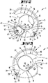
- the shell receptacle 8 or the surface 13 of the first shell part 4 that essentially forms the receptacle extends with reference to a side view according to FIG figure 2 or with reference to a cross-section according to FIG figure 5 along a concave circular arc line viewed from the outside in the direction of the cutting mouth 10 .
- the shell receptacle 9 of the second shell part 5 is also essentially V-shaped with respect to a side view or a cross section transverse to the pivot axis x, having two V-legs 15 and 16 that enclose an angle ⁇ of preferably about 90 degrees to one another , where the V-opening of this shell receptacle 9 faces the shell receptacle 8 of the first shell part 4 running in the shape of a circular arc.
- the cutting mouth 10 results between these shell receptacles 8 and 9.
- the two V-legs 15 and 16 are connected to one another in the area of a V-tip via a circular arc section 17 .
- This arcuate section 17 preferably has a radius r which can correspond to approximately 0.2 to 0.4 times, further approximately 0.25 to 0.3 times the radius r' of the shell receptacle 8 in the form of an arc of a circle.
- the V-legs 15 and 16 which preferably run in a straight line starting from the circular arc section 17 in the side view or in the cross section, can, as also more preferably, extend over approximately the same extent, with the V-leg 15 preferably being in the longitudinal edge 7 close to the axis of the second shell part 5 having the V-shaped shell receptacle 9 .
- the other V-leg 16 is the end, d. H. away from the circular arc section 17, via a curve 23 facing inwards and thus essentially in the direction of the cutting mouth 10.
- This curve 23 can be formed essentially in the form of a section of a circle with reference to the side view or the cross section, more preferably with a radius r ", which can correspond to about 0.5 to 0.75 times, more preferably about 0.6 to 0.7 times the radius r' of the circular shell receptacle 8 of the first shell part 4.
- the geometry of the shell receptacle 9 of the second shell part 5 can also be chosen such that a perpendicular to an angle bisector w of the V-shaped shell receptacle 9 running and the pivot axis x intersects Line u on the one hand intersects the shell receptacle 9 approximately in the transition area from the V-leg 16 into the curvature 23 at point P and on the other hand the V-leg 15 running into the longitudinal edge 7 at a point P'.
- a support section 24 with a triangular cross-section which is delimited on the one hand by an end section of the V-leg 15, with an extension length of about a quarter or a fifth of the total length of the V-leg 16, as well as by the adjoining longitudinal edge 7 and by the geometric line u.
- a plane containing the line u and the pivot axis x is correspondingly penetrated by the area of the shell part 5 that forms the support section 24, as well as by the free end section with the curvature 23.
- the above-described vertical can also have a depression 25 that is essentially triangular in cross section in the first shell part 4 limit which indentation 25 can be adapted in cross-section to the contour of the support section 24 of the second shell part 5.
- the indentation 25 can also offer support for the support section 24, for example to form a limit stop in the inward pivoting direction of the first shell part 4.
- the ratio of the pivot radii t a and t a ′ relating to the pivot axis x can essentially correspond to the above-described ratio of the lengths a and b of the shell parts 4 and 5 .
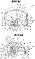
- first shorter shell part 4 is formed by individual rib-like projections 21 spaced apart from one another in the direction of the pivot axis x, which projections 21 engage in depressions 22 formed in regions between the ribs 12 of the second shell part 5 .
- the end face 60 of the first shell part 4 pointing in the pivot direction c moves within the relevant outer pivot radius t a and an inner pivot radius t i .
- These pivoting radii t a and t i correspondingly substantially delimit the end face 60 radially on the outside and radially on the inside.
- the radially outer pivoting radius t a of the first shell part 4 is preferably chosen to be smaller than the radially inner pivoting radius t i ' of the second shell part 5 0.5 to 0.9 times, more preferably about 0.7 to 0.8 times the size of the inner pivoting radius t i ' of the second shell part 5 correspond.
- a limit stop in the closed position of the shell parts 4 and 5 can also be achieved in that in the root region of the projections 21 adjacent regions that space the projections 21 from one another come against the end faces 11 of the ribs 12 of the second shell part 5 .
- the outer wall 26 of the first shell part 4 can overlap the contour of the shell receptacle 9 approximately at the above-described point P of the second shell part 5 cut.
- the shell parts 4 and 5 can have a plurality of rib formations 27, preferably spaced apart from one another in the direction of the pivot axis x. These rib formations 27 accordingly extend transversely to the pivot axis x, and according to the representation in FIG. 11 the rib formations 27 can extend across the entire extent of the second, longer shell part 5 transversely to the pivot axis x. Furthermore, these rib formations 27 of the second shell part 5 can continue in the first shell part 4 at least over a partial section with an interruption caused by the gap 28 resulting in the connection area V between the shell parts 4 and 5 .
- the cutting blade 26 held in the first shell part 4 protrudes in particular with its linear blade in the exemplary embodiment shown Cutting edge 29 at least partially beyond the surface 13 of the associated shell receptacle 8 into the cutting mouth 10.
- the circular section shape of the shell receptacle 8 can accordingly be interrupted by the protruding cutting blade 26, with the projecting area 30 of the cutting blade 26 being depicted as an angle in cross section.
- the cutting blade 26 extends in particular in the area of the cutting edge 29 in a cutting plane S directed transversely to the pivot axis x, in which the above-described contours of the shell receptacles 8 and 9 also result.
- the projecting area of the cutting knife 26 can, as preferred, be formed by a short leg 31 and a long leg 32 , with the long leg 32 being able to be given by a section of the cutting edge 29 .
- the length of the long leg 32 can correspond to approximately half the total length of the cutting edge 29 .
- the long leg 32 and the short leg 31 are preferably aligned at a 90-degree angle to one another, with the long leg 32 formed by a section of the cutting edge 29 in particular also having an acute angle ⁇ of approximately 30 to 45 degrees to a tangent T of the circular arc of the shell receptacle 8 may include.
- the cutting edge 29, starting from the surface 13 of the shell receptacle 8 is inclined away from the pivot axis x in the direction of the free radial end 19.
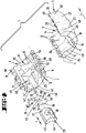
- the cutting blade 26 is more preferably arranged in an exchangeable blade carrier 33 . Preference is given to an essentially end-side arrangement of the cutting blade 26 in relation to the longitudinal extension L in the area of a front side of the blade carrier 33, with the cutting blade 26 being clamped between the block-like blade carrier 33 and a cover plate 34 at the end.
- the mounting of the cutting blade 26 is preferably achieved as a result of a screw connection, with the relevant screw 35 passing through the cover plate 34 and the cutting blade 26 in the area of a bore 36, for threaded engagement in a threaded bore in the blade carrier 33.
- the screw axis is preferably aligned with the pivot axis x .
- the cover plate 34 can have pin-like projections 50 adjacent to a bore 53 for the screw 35, for passing through openings 51 on the blade side and for engaging in cup-like depressions 52 in the blade carrier 30 (compare figures 4 and 15 ).
- the surface of the knife carrier 33 facing the cutting mouth 10 as well as the cover plate 34 is adapted to the circular segment shape of the shell receptacle 8 with reference to a cross section through the cutting device 1, or with reference to a plane running parallel to the cutting plane S, so that the , the shell receptacle 8 forming surface 13 continues in the area of the blade carrier 33 substantially. This results in a surface 37 or 38 curved in the shape of a segment of a circle on the upper side of the knife carrier 33 or the cover plate 34.
- the knife carrier 33 is also arranged in the first shell part 4 in the direction of the pivot axis x so that it can be moved, in particular slidably.
- the arrangement position is also preferably secured by a screw 39 that penetrates the shell part 4 perpendicularly to the direction of displacement f of the blade carrier 33 and is accessible from the outside.
- the receptacle 40 in the blade carrier 33 for the screw 39 extends correspondingly transversely to the direction of displacement f or to the pivot axis x.
- the knife carrier 33 can be guided in the shell part 4 in the manner of rails, for which purpose groove-like guide receptacles 41 and 42 are provided in the shell part 4 and extend in the direction of the pivot axis x.
- These guide receptacles 41 and 42 are preferably provided on both sides with respect to a cross section, but at different heights in a direction perpendicular to the displacement direction f.
- the blade carrier 33 has a guide projection 43 on the side. This engages in an orientation of the knife carrier 33 according to the illustrations in FIG Figures 1 to 8 into the lower guide receptacle 41 spaced farther from the surface 13 of the shell receptacle 8, while a base-side support section 44 with an approximately triangular cross-section is guided in a depression 46 formed on the bottom side of the carrier receptacle 45.
- the cutting knife 26 is preferably arranged essentially in the center of the longitudinal extent L of the shell part 4, with the surface 37 of the knife carrier 33 supplementing the surface 13 of the first shell part 4 forming the shell receptacle 8.
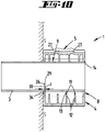
- the blade carrier 33 can essentially be turned around an axis directed in the direction of the screw 39 so that the cutting blade 26 is then arranged close to the edge of the shell part 4 . It results hereafter only a distance to the shell edge 49 depending on the thickness of the cover plate 34 holding the cutting blade 26. There can be a distance d between the bowl edge 49 and the cutting edge 29 of, for example, 2 to 5 mm, further for example about 3 mm (cf figure 10 ). In this constellation, the cutting device 1 can be used in particular to cut sleeves 3, further, for example, so-called drip sleeves, to length.
- the guide projection 43 engages in the other guide seat 42, which is at a smaller distance from the surface 13 of the shell seat 8, while the support section 44 is supported on the tip side in a further depression 47 of the carrier seat 45, which is triangular in cross section.
- the projection of the cutting blade 26, in particular the cutting edge 29, is greater than the central arrangement of the cutting blade 26, with the further surface 38 of the blade carrier 33 supplementing the surface 13 of the shell receptacle 8.
- a dimension e between the transition area of the V-legs 15 and 16 and the intersection point of a bisecting line between the legs 15 and 16 and the surface of the shell receptacle 8 corresponds to approximately 1.3 to 2 times, further about 1.5 times the dimension e in the central and lower arrangement of the cutting blade 26 in relation to the carrier receptacle 45 (cf figure 15 ).
- the surfaces 37 and 38 of the knife carrier 33 extend in cross section or in the side view in a crescent-like or roof-like manner.
- the figures 9 and 10 show the use of the cutting device 1 with a central arrangement of the cutting blade 26 for cutting pipes 2 to length in the course of processing pipes 2 of different diameters.
- the cutting direction g in which the cutting device 1 is rotated around the pipe 2 or the sleeve 3 in the direction of the cutting mouth 10 under the action of external force on the shell parts 4, 5, can be specified on the outside of the cutting device 1 by symbols 48.
- the bolt 18 securing the storage position can be penetrated by the axis body 54 forming the geometric pivot axis x in the area of a slot opening 55 running perpendicularly to the pivot axis x, this preferably in the case of lateral guidance through sections of the second shell part 5 close to the connection area V.
- the bolt 18 is accommodated in a pocket-like, open-edged recess 56 of the second shell part 5 .
- a latching projection 57 that protrudes into this recess 56 in the direction of the latch 18 and can be walked over allows two latching positions of the latch 18 in cooperation with two latching recesses 58 that are spaced apart in the direction of extension of the elongated hole opening 55 .
- a cutting device which is characterized in that the radially outer ends 19, 20 of the shell parts 4, 5 with respect to the pivot axis x can be moved on different radii t a , t a ' , that a radially shorter first shell part 4 up to an overlap to the shell receptacle 9 of the second shell part 5 and that when the shell parts 4, 5 are fully retracted, the radially outer free end 20 of the second shell part 9 is free from overlapping by the first shell part 4 in a pivoting direction c.
- a cutting device which is characterized in that a surface 14 of the second shell part 5 forming the shell receptacle 9 can be pushed through by the radially outer end 19 of the first shell part 4 .
- a cutting device characterized in that the surface 14 of the bowl seat 9 is formed partly as a real surface and partly as an enveloping surface H.
- a cutting device which is characterized in that the penetration in the area of the enveloping surface H can be reached.
- a cutting device which is characterized in that the end faces 11 of inwardly projecting ribs 12 on the second shell part 5 form a surface 14 of the shell receptacle 9 .
- a cutting device which is characterized in that the shell parts 4, 5 have a plurality of spaced rib formations 27 on the outside, which extend transversely to the pivot axis x.
- a cutting device which is characterized in that a rib formation 27 of one shell part 5 continues in alignment in the other shell part 4 with an interruption through the pivot axis x.
- a cutting device which is characterized in that the cutting blade 26 is arranged in an exchangeable blade carrier 33 .
- a cutting device which is characterized in that the knife carrier 33 is arranged in the shell part 4 so that it can be turned.
- a cutting device which is characterized in that the cutting blade 26 is arranged eccentrically with respect to a longitudinal extension L of the cutting device 1 .
- a cutting device which is characterized in that the knife holder 33 is arranged in the shell part 4 so that it can be moved in the direction of the pivot axis x in order to replace the knife holder 33 .
- a cutting device which is characterized in that several guide receptacles 41, 42 are provided for the knife carrier 33, for arranging the knife carrier 33 at different heights in the shell part 4.
- a cutting device which is characterized in that the knife carrier 33 can be fixed in the shell part 4 by means of a screw 39 .
- a cutting device which is characterized in that a receptacle 40 for the screw 39 in the knife carrier 33 extends transversely to a displacement direction f of the knife carrier 33.
- a cutting device characterized in that an opening angle ⁇ of the V-cup seat 9 is between 80 and 100 degrees.
- a cutting device which is characterized in that, with the exception of a cutting blade 26, the shell receptacle 8 of the further shell part 4 is formed in the shape of a segment of a circle.
- a cutting device characterized in that the circular section shape is interrupted by the cutting blade 26 protruding from the shell receptacle 8 and that the protruding portion 30 of the cutting blade 26 is formed in an angle.
- a cutting device which is characterized in that a V-leg 15 of the shell receptacle 9 transitions into an inward-facing curve 23 at the end.
- a cutting device which is characterized in that the curvature 23 is formed in the shape of a segment of a circle.
Abstract
Die Erfindung betrifft ein Schneidgerät (1) zum Ablängen von Rohren (2) oder Hülsen (3), mit einem Schneidmaul (10), bestehend aus zwei Schalenteilen (4, 5), einem ersten und einem zweiten Schalenteil (4, 5), mit jeweils einer Schalenaufnahme (8, 9), wobei die Schalenteile (4, 5) zueinander um eine Schwenkachse (x) verschwenkbar sind. Um ein Schneidgerät der in Rede stehenden Art handhabungstechnisch und ergonomisch weiter zu verbessern, wird vorgeschlagen, dass die mit Bezug auf die Schwenkachse (x) radial äußeren Enden (19, 20) der Schalenteile (4, 5) auf unterschiedlichen Radien (t<sub>a</sub>, t<sub>a'</sub>) bewegbar sind, dass ein radial kürzeres erstes Schalenteil (4) bis in eine Überdeckung zu der Schalenaufnahme (9) des zweiten Schalenteils (5) bewegbar ist und dass bei vollständig zusammengefahrenen Schalenteilen (4, 5) das radial äußere freie Ende (20) des zweiten Schalenteils (9) in einer Schwenkrichtung (c) frei von einer Überdeckung durch das erste Schalenteil (4) ist.The invention relates to a cutting device (1) for cutting pipes (2) or sleeves (3) to length, with a cutting mouth (10) consisting of two shell parts (4, 5), a first and a second shell part (4, 5), each having a shell receptacle (8, 9), the shell parts (4, 5) being pivotable relative to one another about a pivot axis (x). In order to further improve the handling and ergonomics of a cutting device of the type in question, it is proposed that the radially outer ends (19, 20) of the shell parts (4, 5) with respect to the pivot axis (x) should have different radii (t<sub >a</sub>, t<sub>a'</sub>) can be moved, that a radially shorter first shell part (4) can be moved until it overlaps the shell receptacle (9) of the second shell part (5) and that when the shell parts (4, 5) are fully retracted, the radially outer free end (20) of the second shell part (9) is not covered by the first shell part (4) in a pivoting direction (c).
Description
Die Erfindung betrifft ein Schneidgerät zum Ablängen von Rohren oder Hülsen, mit einem Schneidmaul, bestehend aus zwei Schalenteilen, einem ersten und einem zweiten Schalenteil, mit jeweils einer Schalenaufnahme, wobei die Schalenteile zueinander um eine Schwenkachse verschwenkbar sind.The invention relates to a cutting device for cutting pipes or sleeves to length, with a cutting mouth consisting of two shell parts, a first and a second shell part, each with a shell receptacle, the shell parts being pivotable relative to one another about a pivot axis.
Auch betrifft die Erfindung ein Schneidgerät zum Ablängen von Rohren oder Hülsen, mit einem Schneidmaul, bestehend aus zwei Schalenteilen, einem ersten und einem zweiten Schalenteil, mit jeweils einer Schalenaufnahme, wobei die Schalenteile zueinander um eine Schwenkachse verschwenkbar sind, wobei jedenfalls in einem Schalenteil ein Schneidmesser angeordnet ist.The invention also relates to a cutting device for cutting pipes or sleeves to length, with a cutting mouth, consisting of two shell parts, a first and a second shell part, each with a shell receptacle, the shell parts being pivotable relative to one another about a pivot axis, with at least one shell part Cutting blade is arranged.
Zudem betrifft die Erfindung ein Schneidgerät zum Ablängen von Rohren oder Hülsen, mit einem Schneidmaul, bestehend aus zwei Schalenteilen, einem ersten und einem zweiten Schalenteil, mit jeweils einer Schalenaufnahme, wobei die Schalenteile zueinander um eine Schwenkachse verschwenkbar sind und ein Schalenteil eine V-förmige Schalenaufnahme aufweist.The invention also relates to a cutting device for cutting pipes or sleeves to length, with a cutting mouth, consisting of two shell parts, a first and a second shell part, each with a shell receptacle, the shell parts being pivotable relative to one another about a pivot axis and one shell part having a V-shape Has shell recording.
Schneidgeräte der in Rede stehenden Art sind bekannt, insbesondere zum Schneiden von Rohren, weiter insbesondere Kunststoffrohren. Solche Rohre, insbesondere Kunststoffrohre, können beispielsweise im Sanitärbereich als Wasserzulauf-, und/oder Wasserablaufrohre dienen, darüber hinaus können sie beispielsweise auch bei einer Elektroinstallation zur Anwendung kommen, insbesondere zur schützenden Aufnahme von einem oder mehreren Kabeln. So können auch weiter beispielsweise mittels solcher Schneidgeräte Hochtemperatur-Abwasserrohre oder auch Elektro-Leerrohre geschnitten werden. Auch sind derartige Schneidgerät bekannt, mittels welchen Hülsen, weiter beispielsweise sogenannte Tropfhülsen, abgelängt werden können.Cutting devices of the type in question are known, in particular for cutting pipes, more particularly plastic pipes. Such pipes, in particular plastic pipes, can serve as water inlet and/or water outlet pipes in the sanitary sector, for example, and they can also be used in electrical installations, in particular for the protective accommodation of one or more cables. For example, high-temperature sewage pipes can also be cut by means of such cutting devices or electrical conduits are cut. Cutting devices of this type are also known, by means of which sleeves, further, for example, so-called drip sleeves, can be cut to length.
Bekannte Ausführungen solcher Schneidgeräte weisen bevorzugt zwei gelenkig miteinander verbundene Schalenteile auf, welche relativ zueinander um eine in Längserstreckungsrichtung des Schneidgeräts insgesamt ausgerichtete Schwenkachse aus einer Öffnungsstellung in eine Arbeitsstellung und zurück verschwenkbar sind. In diesem Zusammenhang wird beispielsweise auf die
Im Hinblick auf den vorbeschriebenen Stand der Technik wird eine Aufgabe der Erfindung darin gesehen, ein Schneidgerät der in Rede stehenden Art insbesondere handhabungstechnisch und/oder ergonomisch verbessert auszugestalten.In view of the prior art described above, one object of the invention is to design a cutting device of the type in question that is improved in particular in terms of handling and/or ergonomics.
Eine mögliche Lösung der Aufgabe ist nach einem ersten Erfindungsgedanken bei einem Schneidgerät gegeben, bei welchem darauf abgestellt ist, dass mit Bezug auf die Schwenkachse radial äußere Enden der Schalenteile auf unterschiedlichen Radien bewegbar sind, dass ein radial kürzeres erstes Schalenteil bis in eine Überdeckung zu der Schalenaufnahme des zweiten Schalenteils bewegbar ist und dass bei vollständig zusammengefahrenen Schalenteilen das radial äußere freie Ende des zweiten Schalenteils in einer Schwenkrichtung frei von einer Überdeckung durch das erste Schalenteil ist.According to a first idea of the invention, a possible solution to the problem is given in a cutting device, in which the aim is that radially outer ends of the shell parts can be moved on different radii with respect to the pivot axis, that a radially shorter first shell part overlaps the Shell receptacle of the second shell part is movable and that when the shell parts are fully retracted, the radially outer free end of the second shell part is free in a pivoting direction from being overlapped by the first shell part.
Zufolge der vorgeschlagenen Ausgestaltung der das Schneidgerät im Wesentlichen bildenden Schalenteile ergibt sich unter Ermöglichung eines vergleichsweise großen Einsatzbereiches eine ergonomisch günstige Handhabbarkeit des Schneidgeräts. Das Schneidgerät erweist sich in der Arbeitsstellung, darüber hinaus aber auch in einer möglichen Verwahrstellung, als kompakt. Eine einhändige Bedienung des Schneidgeräts im Zuge eines Schneidvorgangs ist zufolge der vorgeschlagenen Geometrie über einen vergleichsweise großen Durchmesserbereich des zu schneidenden Rohres beziehungsweise der zu schneidenden Hülse von beispielsweise 10 mm bis hin zu 80 mm, weiter beispielsweise 20 mm bis 50 mm gegeben.As a result of the proposed configuration of the shell parts that essentially form the cutting device, ergonomic handling results while enabling a comparatively large area of use of the cutter. The cutting device proves to be compact in the working position, but also in a possible storage position. According to the proposed geometry, the cutting device can be operated with one hand during a cutting process over a comparatively large diameter range of the pipe to be cut or the sleeve to be cut, for example 10 mm to 80 mm, further for example 20 mm to 50 mm.
Das radial äußere Ende des kürzeren ersten Schalenteils kann sich dabei um die geometrische Schwenkachse auf einem Radius bewegen, welcher beispielsweise etwa dem 0,5- bis 0,85-Fachen, weiter etwa dem 0,65- bis 0,75-Fachen des Radius des äußeren Endes des zweiten längeren Schalenteils entsprechen kann. Dabei kann zumindest über einen Schwenkbereich, insbesondere über einen Schwenkbereich, in welchem Rohre oder Hülsen mit vergleichsweise geringem Durchmesser geschnitten werden oder in welchem die Schalenteile aneinander zur Anlage kommen können, das radial kürzere erstes Schalenteil insbesondere im Bereich des freien Endes in eine zumindest abschnittweise Überdeckung in eine bezüglich der Schwenkachse radialen Richtung zu dem zweiten Schalenteil gelangen, wodurch weiter eine kompakte Bauform des Schneidgerätes bei ergonomisch günstiger Ausgestaltung erreicht werden kann.The radially outer end of the shorter first shell part can move around the geometric pivot axis on a radius which is, for example, approximately 0.5 to 0.85 times, further approximately 0.65 to 0.75 times the radius of the outer end of the second longer shell part. At least over a pivoting range, in particular over a pivoting range in which pipes or sleeves with a comparatively small diameter are cut or in which the shell parts can come into contact with one another, the radially shorter first shell part can be overlapped at least in sections, especially in the area of the free end reach the second shell part in a direction that is radial with respect to the pivot axis, as a result of which a compact design of the cutting device can be achieved with an ergonomically favorable configuration.
Die Überdeckung kann, wie auch bevorzugt, insbesondere in eine Richtung betrachtet entlang der Schwenkachse in radialer Richtung gegeben sein. Das kürzere erste Schalenteil kann entsprechend zumindest in einer Schwenkstellung teilweise quasi in das zweite Schalenteil eingeschachtelt werden. Dabei ergibt sich insbesondere in der vollständig zusammengefahrenen Stellung der Schalenteile eine Ineinanderschachtelung, in welcher das freie Ende des längeren zweiten Schalenteils in Verlängerung des Krümmungsverlaufes dieses zweiten Schalenteils nicht von dem ersten Schalenteil oder Abschnitten des ersten Schalenteiles überdeckt ist. Dies betrifft insbesondere eine Stirnfläche des längeren zweiten Schalenteils. Eine Stirnfläche des ersten Schalenteils bewegt sich auf Radien, die innerhalb von Radien der Stirnfläche des zweiten Schalenteils liegen.As is also preferred, the overlap can be provided in the radial direction, in particular viewed in one direction along the pivot axis. Correspondingly, the shorter first shell part can be partially boxed into the second shell part, at least in one pivoted position. This results in particular in the fully retracted position of the shell parts nesting in which the free end of the longer second shell part in extension of the curvature of this second shell part not from the first shell part or sections of the first Shell part is covered. This relates in particular to an end face of the longer second shell part. A face of the first shell portion moves at radii that are within radii of the face of the second shell portion.
Nach einem weiteren Erfindungsgedanken kann eine Lösung der Aufgabe dadurch erreicht sein, dass die Schalenteile außenseitig mehrere beabstandete Rippenausformungen aufweisen, die sich quer zu der Schwenkachse erstrecken.According to a further idea of the invention, the object can be achieved in that the shell parts have a plurality of spaced rib formations on the outside, which extend transversely to the pivot axis.
Hieraus ergibt sich insbesondere eine ergonomisch günstige Gestaltung der Greifflächen des Schneidgeräts. Die in Radialrichtung vorstehenden Rippenausformungen belassen, in Richtung der Schwenkachse betrachtet, zwischen sich bevorzugt rinnenförmige Vertiefungen. Eine solche Vertiefung ist weiter bevorzugt ergonomisch günstig gebildet in Art einer Kehle, in welcher der Finger, bevorzugt beidseitig seitlich geführt durch die Rippenausformung, einliegen kann.This results in particular in an ergonomically favorable design of the gripping surfaces of the cutting device. The rib formations protruding in the radial direction leave, viewed in the direction of the pivot axis, preferably channel-shaped depressions between them. Such an indentation is more preferably formed in an ergonomically favorable manner in the manner of a groove in which the finger can lie, preferably guided laterally on both sides by the rib formation.
So kann ein Schalenteil außenseitig drei oder mehr, beispielsweise bis hin zu fünf derartige Rippenausformungen aufweisen, welche weiter bevorzugt in Richtung der Schwenkachse gleichmäßig zueinander beabstandet sein können. Entsprechend können sich weiter zwei, drei oder vier kehlartige Vertiefungen ergeben, in welchen bei Benutzung des Schneidgerätes eine entsprechende Anzahl an Fingern einliegen kann.Thus, a shell part can have three or more, for example up to five, such rib formations on the outside, which more preferably can be evenly spaced from one another in the direction of the pivot axis. Correspondingly, there can also be two, three or four throat-like indentations in which a corresponding number of fingers can lie when the cutting device is used.
Derartige Rippenausformungen und die dabei sich ergebende Vertiefungen können handhabungsgünstig, wie auch bevorzugt, außenseitig beider Schalenteile vorgesehen sein.Such rib formations and the resulting indentations can be provided on the outside of both shell parts, which is favorable for handling and is also preferred.
Auch kann gemäß einem weiteren Erfindungsgedanken die Aufgabe dadurch gelöst sein, dass das Schneidmesser in einem auswechselbaren Messerträger angeordnet ist.According to a further idea of the invention, the object can also be achieved in that the cutting blade is arranged in an exchangeable blade carrier.
Das Messer kann entsprechend zusammen mit dem Messerträger aus dem Schneidgerät entfernt werden, beispielsweise zum Auswechseln des Schneidmessers allein oder zusammen mit dem Messerträger bei entsprechender Abnutzung. Auch kann das Schneidmesser allein oder zusammen mit dem Messerträger beispielsweise für bestimmte Anwendungen gegen ein alternatives Schneidmesser gewechselt werden.Accordingly, the blade can be removed from the cutting device together with the blade carrier, for example to replace the cutting blade alone or together with the blade carrier when it has become worn. The cutting blade can also be exchanged for an alternative cutting blade alone or together with the blade carrier, for example for specific applications.
Darüber hinaus kann zufolge Anordnung des Schneidmessers an einem Messerträger gegebenenfalls auch die Positionierung des Schneidmessers innerhalb des Schneidgeräts, insbesondere innerhalb des das Schneidmesser mit dem Messerträger tragenden Schalenteils verändert werden.In addition, as a result of the arrangement of the cutting blade on a blade carrier, the positioning of the cutting blade within the cutting device, in particular within the shell part carrying the cutting blade with the blade carrier, can also be changed if necessary.
In bevorzugter Ausgestaltung ist dabei das Schneidmesser lösbar an dem Messerträger gehalten. Die diesbezügliche Verbindung kann dabei, wie auch bevorzugt, mit einem üblichen Werkzeug aufgehoben beziehungsweise hergestellt werden. So ist diesbezüglich eine Schraubbefestigung bevorzugt.In a preferred embodiment, the cutting blade is detachably held on the blade carrier. The relevant connection can, as is also preferred, be canceled or made with a conventional tool. In this respect, a screw fastening is preferred.
Eine weitere mögliche Lösung der Aufgabe kann bei einem Schneidgerät dadurch gegeben sein, dass ein Öffnungswinkel der V-Schalenaufnahme zwischen 80 und 100 Grad liegt.A further possible solution to the problem can be given in a cutting device in that an opening angle of the V-shaped receptacle is between 80 and 100 degrees.
Der vorteilhafte Öffnungswinkel der V-Schenkel der V-Schalenaufnahme bietet eine günstige umfangsmäßige Abstützung des zu schneidenden Rohres beziehungsweise der zu schneidenden Hülse über einen vergleichsweise großen Durchmesser-Bereich, wobei weiter durch V-förmige Anstellung der Aufnahmeränder zugleich eine zentrierte Ausrichtung des zu schneidenden Werkstücks erreichbar ist.The advantageous opening angle of the V-legs of the V-cup receptacle offers favorable circumferential support of the pipe to be cut or the sleeve to be cut over a comparatively large diameter range, with further V-shaped employment of the Recording edges at the same time a centered alignment of the workpiece to be cut can be reached.
Bevorzugt ist dabei weiter ein diesbezüglicher Öffnungswinkel zwischen etwa 85 und etwa 95 Grad, weiter bevorzugt etwa 90 Grad.A relevant opening angle of between approximately 85 and approximately 95 degrees is preferred, more preferably approximately 90 degrees.
Die Merkmale der vorbeschriebenen Ansprüche sind sowohl jeweils für sich wesentlich als auch in jeder Kombination miteinander von Bedeutung, wobei weiter Merkmale eines unabhängigen Anspruchs mit den Merkmalen eines weiteren unabhängigen Anspruchs kombinierbar sind, weiter auch mit nur einzelnen Merkmalen eines oder mehrerer der weiteren unabhängigen Ansprüche. Nicht zuletzt sind auch die Merkmale einzeln oder in einer der genannten Kombinationen an einer tatsächlichen Ausführungsform des Schneidgeräts (zusammen) verwirklichbar.The features of the claims described above are important both individually and in any combination with one another, with features of an independent claim being able to be combined with the features of a further independent claim, and also with only individual features of one or more of the further independent claims. Last but not least, the features can also be realized (together) individually or in one of the combinations mentioned on an actual embodiment of the cutting device.
Weitere Merkmale der Erfindung sind nachstehend, auch in der Figurenbeschreibung, oftmals in ihrer bevorzugten Zuordnung zum Gegenstand des Anspruchs 1 und/oder des oder der weiteren unabhängigen Ansprüche oder zu Merkmalen weiterer Ansprüche erläutert. Sie können aber auch in einer Zuordnung zu nur einzelnen Merkmalen des Anspruchs 1 und/oder des oder der weiteren unabhängigen Ansprüche oder des jeweiligen weiteren Anspruchs oder jeweils unabhängig von Bedeutung sein.Further features of the invention are explained below, also in the description of the figures, often in their preferred association with the subject matter of
So kann gemäß einer möglichen Weiterbildung vorgesehen sein, dass eine die Schalenaufnahme bildende Fläche des zweiten Schalenteils von dem radial äußeren Ende des ersten Schalenteils durchsetzt ist. Zufolge dieser Durchsetzung kann die vorbeschriebene Überdeckung der Schalenteile erreicht sein. Das erste Schalenteil kann dabei endseitig, d. h. abgewandt der Schwenkachse, mit einem Endbereich die Fläche des zweiten Schalenteils durchsetzen, welcher Endbereich sich beispielsweise etwa über ein Achtel bis ein Viertel, weiter bevorzugt etwa ein Sechstel der quer zur Ausrichtung der Schwenkachse betrachteten Erstreckungslänge des ersten Schalenteils ausgehend von der Schwenkachse erstrecken kann.Thus, according to a possible development, it can be provided that a surface of the second shell part forming the shell receptacle is penetrated by the radially outer end of the first shell part. As a result of this enforcement, the above-described overlapping of the shell parts can be achieved. The first shell part can penetrate the surface of the second shell part with an end area, i.e. facing away from the pivot axis. which end region can extend, for example, over approximately one eighth to one quarter, more preferably approximately one sixth of the length of the first shell part, viewed transversely to the orientation of the pivot axis, starting from the pivot axis.
Weiter kann sich eine solche Durchsetzung gegebenenfalls über einen Schwenkbereich des ersten Schalenteils relativ zu dem zweiten Schalenteil von etwa 10 bis 20 Grad, weiter etwa 15 Grad ergeben. Dabei kann das erste Schalenteil ausgehend von einer ersten Berührung der Fläche der Schalenaufnahme des zweiten Schalenteils bevorzugt noch um einen Schwenkwinkel von beispielsweise etwa 15 Grad unter bevorzugter Einhaltung der Überdeckung zu dem zweiten Schalenteil in Richtung auf die zusammengefahrene Stellung verschwenken.Furthermore, such enforcement can optionally result over a pivoting range of the first shell part relative to the second shell part of about 10 to 20 degrees, further about 15 degrees. Starting from a first contact with the surface of the shell receptacle of the second shell part, the first shell part can preferably still pivot by a pivoting angle of, for example, about 15 degrees while preferably maintaining the overlap with the second shell part in the direction of the retracted position.
Die Fläche der Schalenaufnahme des zweiten Schalenteils kann dabei teilweise als reale Fläche und teilweise als Hüllfläche gebildet sein. Die gedachte Hüllfläche ergibt sich dabei bevorzugt aus einer die realen Flächen in ihrer Flächenerstreckung verbindenden Fläche. Bevorzugt ergibt sich zumindest abschnittweise eine kreisförmige und/oder ebene Hüllfläche. Dabei kann sich die Hüllfläche weiter, insbesondere in Erstreckungsrichtung der Schwenkachse betrachtet, zwischen den realen Flächen ergeben.The surface of the shell receptacle of the second shell part can be formed partly as a real surface and partly as an enveloping surface. The imaginary enveloping surface preferably results from a surface that connects the real surfaces in their surface extent. A circular and/or planar enveloping surface preferably results at least in sections. In this case, the enveloping surface can further arise between the real surfaces, in particular when viewed in the direction of extension of the pivot axis.
Bevorzugt ist die Durchsetzung im Bereich der Hüllfläche erreicht. So ist bevorzugt die Durchsetzung zwischen den Bereichen der realen Flächen der Schalenaufnahme ermöglicht, beispielsweise durch eine schlitzförmige Ausgestaltung der Schalenaufnahme oder durch Bildung von zu durchgreifenden Öffnungen.The enforcement is preferably achieved in the area of the enveloping surface. In this way, it is preferably possible to pass through between the areas of the real surfaces of the shell receptacle, for example by designing the shell receptacle in the form of a slot or by forming openings that can be reached through.
Die Stirnflächen von an dem zweiten Schalenteil nach innen, d. h. in Richtung auf das Schneidmaul vorstehenden Rippen können gemäß einer Weiterbildung eine Fläche, so weiter insbesondere die reale Fläche, bilden.The end faces from inwards at the second shell part, i. H. According to a further development, ribs protruding in the direction of the cutting mouth can form a surface, in particular the real surface.
Bezüglich der Rippenausformungen außenseitig auf zumindest einem der Schalenteile kann gemäß einer Weiterbildung vorgesehen sein, dass sich eine Rippenausformung des einen Schalenteils mit Unterbrechung durch die Schwenkachse fluchtend in dem anderen Schalenteil fortsetzt. Eine solche Fortsetzung der Rippenausformungen und somit auch daraus resultierend eine Fortsetzung der beispielsweise kehlartigen Fingerausformungen über den Verbindungsbereich der beiden Schalenteile hinaus erweist sich insbesondere handhabungstechnisch und ergonomisch von Vorteil. Das Schneidgerät ist auch bei einem einhändigen Erfassen desselben über den Verbindungs- beziehungsweise Schwenkbereich hinaus sicher gegriffen.With regard to the rib formations on the outside of at least one of the shell parts, according to a further development it can be provided that a rib formation of one shell part continues flush with the other shell part with an interruption caused by the pivot axis. Such a continuation of the rib formations and thus also resulting therefrom a continuation of the, for example, throat-like finger formations beyond the connecting region of the two shell parts proves to be particularly advantageous in terms of handling and ergonomics. The cutting device is securely gripped even if it is grasped with one hand beyond the connection or pivoting area.
Hinsichtlich der Anordnung des Schneidmessers kann gemäß einer Weiterbildung des Erfindungsgegenstandes vorgesehen sein, dass der Messerträger wendbar in dem Schalenteil angeordnet ist. Dabei kann weiter der Messerträger in der Anordnungsstellung eine im Wesentlichen in Erstreckungsrichtung der Schwenkachse gerichtete Längserstreckung aufweisen. Der Messerträger kann weiter bevorzugt im Wesentlichen um eine senkrecht zur geometrischen Schwenkachse verlaufende Körperachse gewendet werden, sodass ein Ende des Messerträgers nach dem Wenden um bevorzugt 180 Grad in die entgegengesetzte Richtung wie zuvor weist.With regard to the arrangement of the cutting blade, it can be provided according to a development of the subject matter of the invention that the blade carrier is arranged in a reversible manner in the shell part. In this case, the blade carrier can also have a longitudinal extent directed essentially in the direction of extent of the pivot axis in the arrangement position. The blade carrier can further preferably be turned substantially about a body axis running perpendicularly to the geometric pivot axis, so that after turning, one end of the blade carrier preferably points 180 degrees in the opposite direction as before.
Durch ein Wenden des Messerträgers kann eine Veränderung der Positionierung des Schneidmessers erreicht werden und/oder eine Veränderung der im Zuge des Schneidvorgangs wirksamen Schneidkante des Schneidmessers. So kann mit Wenden des Messerträgers beispielsweise eine geradlinig verlaufende wirksame Schneidkante gegen eine konkav oder konvex verlaufende wirksame Schneidkante gewechselt werden. Auch kann weiter beispielsweise durch Wenden des Messerträgers die Schneidtiefe des Schneidmessers verändert werden.By turning the knife carrier, the positioning of the cutting knife can be changed and/or the cutting edge of the cutting knife that is effective in the course of the cutting process can be changed. For example, turning the knife carrier can result in a straight line effective cutting edge can be exchanged for a concave or convex effective cutting edge. The cutting depth of the cutting blade can also be changed, for example by turning the blade carrier.
Ist durch Wenden des Messerträgers eine Veränderung der Positionierung des Schneidmessers erreichbar, so kann gemäß einer möglichen Ausgestaltung in einer Ausrichtung des Messerträgers bezüglich der Längserstreckung des Schneidgeräts, insbesondere bezüglich der Längserstreckung des den Messerträger tragenden Schalenteils, im Wesentlichen eine mittige Anordnung des Schneidmessers gegeben sein. In der Wendestellung des Messerträgers kann die Positionierung des Schneidmessers dahingehend verändert vorliegen, dass das Schneidmesser bezüglich der Längserstreckung des Schneidgerätes außermittig angeordnet ist. So kann weiter in dieser Messerträger-Ausrichtung das Schneidmesser beispielsweise randnah des den Messerträger halternden Schalenteils positioniert sein, weiter beispielsweise zur Nutzung des Schneidgerätes zur Ablängung sogenannter Tropfhülsen.If a change in the positioning of the cutting blade can be achieved by turning the blade carrier, according to one possible embodiment, the blade carrier can be arranged essentially in the middle with respect to the longitudinal extension of the cutting device, in particular with regard to the longitudinal extension of the shell part carrying the knife carrier. In the turning position of the blade carrier, the positioning of the cutting blade can be changed in such a way that the cutting blade is arranged eccentrically with respect to the longitudinal extent of the cutting device. Thus, in this knife carrier orientation, the cutting knife can be positioned, for example, near the edge of the shell part holding the knife carrier, further, for example, for using the cutting device for cutting so-called drip sleeves to length.
Zum Auswechseln des Messerträgers kann der Messerträger gemäß einer möglichen Ausgestaltung in Richtung der Schwenkachse beweglich in dem Schalenteil angeordnet sein. Diesbezüglich kann sich eine Verschiebbarkeit, gegebenenfalls, wie auch bevorzugt, nach Aufhebung einer den Messerträger in dem Schalenteil fixierenden Ausbildung, innerhalb des Schalenteils ergeben. Hierzu kann weiter gegebenenfalls eine die Schiebeverlagerbarkeit ermöglichende Führung gegeben sein, beispielsweise in Art einer schienenartigen Führung.In order to replace the blade carrier, the blade carrier can be arranged in the shell part so that it can move in the direction of the pivot axis, according to one possible embodiment. In this regard, displaceability can result within the shell part, optionally, as is also preferred, after a configuration that fixes the knife carrier in the shell part has been removed. For this purpose, a guide that enables the sliding displaceability can also be provided, for example in the form of a rail-like guide.
So können weiter für den Messerträger mehrere Führungsaufnahmen vorgesehen sein, die (auch) eine höhenmäßig unterschiedliche Anordnung des Messerträgers in dem Schalenteil ermöglichen können. Entsprechend können sich je nach Anordnung des Messerträgers in der einen oder anderen Führungsaufnahme unterschiedliche Vorstandslagen der Schneidkante über die Fläche der Schneidaufnahme hinaus in Richtung auf das Schneidmaul ergeben. Bevorzugt sind in diesem Zusammenhang zwei Führungsaufnahmen vorgesehen, zur unterschiedlichen Anordnung des Messerträgers in zwei unterschiedlichen Höhen. Auch können mehr als zwei, beispielsweise drei oder vier, solcher Führungsaufnahmen in dem Schalenteil ausgebildet sein.In this way, several guide receptacles can be provided for the knife carrier, which (also) have a different arrangement of the height Can allow knife carrier in the shell part. Correspondingly, depending on the arrangement of the blade carrier in one or the other guide mount, the cutting edge can project in different positions beyond the surface of the cutting mount in the direction of the cutting mouth. In this context, two guide receptacles are preferably provided for the different arrangement of the knife carrier at two different heights. More than two, for example three or four, such guide receptacles can also be formed in the shell part.
Der Messerträger kann in dem Schalenteil beispielsweise mittels einer Schraube festsetzbar sein. Unter Nutzung beispielsweise einer solchen Schraube ist der Messerträger bevorzugt in beiden Wendestellungen in dem Schalenteil fixierbar. Die Führungsaufnahmen wirken dabei weiter bevorzugt drehhindernd.The knife carrier can be fixed in the shell part, for example by means of a screw. Using, for example, such a screw, the knife carrier can preferably be fixed in both turning positions in the shell part. The guide receptacles more preferably have a rotation-preventing effect.
Eine Aufnahme für die Schraube in dem Messerträger, wie auch die mit der Schraube zusammenwirkende Aufnahme in dem Schalenteil, erstreckt sich bevorzugt quer zu einer Verschieberichtung des Messerträgers. Die Verschieberichtung ist dabei weiter bevorzugt gleichgerichtet zur Erstreckungsrichtung der Schwenkachse.A receptacle for the screw in the knife carrier, as well as the receptacle in the shell part that interacts with the screw, preferably extends transversely to a displacement direction of the knife carrier. The direction of displacement is more preferably in the same direction as the direction in which the pivot axis extends.
In weiterer Ausgestaltung kann mit Ausnahme des Schneidmessers die Schalenaufnahme des Weiteren (ersten) Schalenteils kreisabschnittsförmig gebildet sein. Das Schalenteil ist somit als eine Kreisabschnittsform gebildet. Mit Bezug auf eine Projektion der Anlagefläche der Schalenaufnahme in eine quer zur Schwenkachse ausgerichtete Ebene kann sich eine Kreislinienform mit gleichbleibendem Radius oder auch eine zusammengesetzte Kreislinienform mit unterschiedlichen Radien ergeben. Weiter ergibt sich diese Kreisabschnittsform des Schalenteils insbesondere in der quer zur Schwenkachse sich ergebenden Schnittebene.In a further embodiment, with the exception of the cutting blade, the shell receptacle can also be formed in the shape of a segment of a circle. The shell part is thus formed as a pie shape. With reference to a projection of the contact surface of the shell receptacle in a plane aligned transversely to the pivot axis, a circular shape with a constant radius or a composite circular shape with different radii can result. This segment of a circle shape also results of the shell part, in particular in the sectional plane that results transversely to the pivot axis.
Diese Kreisabschnittsform kann durch das gegenüber der Schalenaufnahme vorstehende Schneidmesser unterbrochen sein. Entsprechend ergibt sich in dem Bereich des Schneidmauls eine Vorstandslage zumindest eines Teilbereiches des Schneidmessers über die Schalenaufnahme hinaus, wobei dieser Vorstandsbereich des Schneidmessers bevorzugt winkelartig gebildet ist. Es handelt sich bei diesem Vorstandsbereich somit um einen winkelartigen Vorstandsbereich. So kann sich mit Bezug auf die vorbeschriebene Projektion in eine Ebene quer zur Schwenkachse ein Vorstandsbereich ergeben mit zwei in einem Winkel von bevorzugt 75 bis 115 Grad, weiter bevorzugt etwa 90 Grad zueinander einschließenden Kanten, wobei zumindest eine Kante eine Schneidkante bildet. Zumindest eine dieser Kanten kann sich als gedachte, geradlinig Enden beispielsweise der Schneidkante verbindende Linie darstellen.This circular section shape can be interrupted by the cutting blade that protrudes in relation to the shell receptacle. Correspondingly, in the area of the cutting mouth, at least a partial area of the cutting blade protrudes beyond the shell receptacle, with this protruding area of the cutting blade preferably being formed in an angle. This board area is therefore an angular board area. With reference to the above-described projection into a plane transverse to the pivot axis, a projection area can result with two edges enclosing one another at an angle of preferably 75 to 115 degrees, more preferably about 90 degrees, with at least one edge forming a cutting edge. At least one of these edges can be presented as an imaginary line connecting straight ends, for example, of the cutting edge.
Der winkelartige Vorstandsbereich des Schneidmessers kann entsprechend weiter durch einen Kurzschenkel und einen Langschenkel gebildet sein. Der Langschenkel kann dabei weiter, wie auch bevorzugt, ein Teilabschnitt der Schneidkante des Schneidmessers sein oder auch ein Teilabschnitt der vorbeschriebenen gedachten geraden Linie.The angled projection area of the cutting blade can accordingly be further formed by a short leg and a long leg. The long leg can also, as is also preferred, be a section of the cutting edge of the cutting blade or also a section of the imaginary straight line described above.
In handhabungstechnisch vorteilhafter Weise kann ein V-Schenkel der Schalenaufnahme des einen (zweiten) Schalenteils endseitig in eine nach innen in Richtung auf das Schneidmaul gewandte Krümmung übergehen. So kann weiter, insbesondere ausgehend von der weiter bevorzugt verrundet ausgestalteten V-Spitze jeder V-Schenkel in der Ebene quer zur Schwenkachse (zunächst) zumindest annähernd geradlinig verlaufen. Der geradlinige Verlauf des bevorzugt der Schwenkachse abgewandten V-Schenkels geht in Richtung auf sein radial äußeres freies Ende in die vorbeschriebene Krümmung über. Mit diesem endseitig gekrümmten Endbereich übergreift das längere zweite Schalenteil das erste Schalenteil mit radialem Abstand, insbesondere bei vollständig zusammengefahrenen Schalenteilen.In a way that is advantageous in terms of handling, a V-leg of the shell receptacle of the one (second) shell part can change at the end into an inward curvature in the direction of the cutting mouth. Thus, in particular starting from the more preferably rounded V tip, each V leg can (initially) run at least approximately in a straight line in the plane transverse to the pivot axis. The rectilinear course of the V-leg, which preferably faces away from the pivot axis, goes in the direction of its radially outer free end in the above curvature. With this end region curved at the end, the longer second shell part overlaps the first shell part at a radial distance, in particular when the shell parts are completely moved together.
Die vorbeschriebene Krümmung des V-Schenkels kann, wie auch bevorzugt, im Wesentlichen kreisabschnittsförmig gebildet sein.The above-described curvature of the V-leg can, as is also preferred, be essentially in the form of a segment of a circle.
Die vor- und nachstehend angegebenen Bereiche bzw. Wertebereiche oder Mehrfachbereiche schließen hinsichtlich der Offenbarung auch sämtliche Zwischenwerte ein, insbesondere in 1/10- Schritten der jeweiligen Dimension, gegebenenfalls also auch dimensionslos. Beispielsweise beinhaltet die Angabe 80 bis 100° auch die Offenbarung von 80,1 bis 100 Grad, 80 bis 99,9 Grad, 80,1 bis 99,9 Grad, etc., die Offenbarung von 0,5- bis 0,85-Fach auch die Offenbarung von 0,6- bis 0,85-Fach, 0,5- bis 0,75-Fach, 0,6- bis 0,75-Fach etc. Diese Offenbarung kann einerseits zur Eingrenzung einer genannten Bereichsgrenze von unten und/oder oben, alternativ oder ergänzend aber zur Offenbarung eines oder mehrerer singulärer Werte aus einem jeweilig angegebenen Bereich dienen.The ranges or value ranges or multiple ranges specified above and below also include all intermediate values with regard to the disclosure, in particular in steps of 1/10 of the respective dimension, ie possibly also dimensionless. For example, the statement 80 to 100° also includes the revelation of 80.1 to 100 degrees, 80 to 99.9 degrees, 80.1 to 99.9 degrees, etc., the revelation of 0.5 to 0.85 degrees. Subject also the disclosure of 0.6 to 0.85 times, 0.5 to 0.75 times, 0.6 to 0.75 times, etc. On the one hand, this disclosure can be used to delimit a specified range limit from below and/or above, alternatively or additionally, serve to disclose one or more singular values from a respectively specified range.
Im Folgenden wird die Erfindung anhand von Ausführungsbeispielen näher erläutert. Es zeigen:
- Fig. 1
- ein Schneidgerät in perspektivischer Darstellung;
- Fig. 2
- das Schneidgerät in einer Seitenansicht;
- Fig. 3
- das Schneidgerät in einer weiteren Seitenansicht;
- Fig. 4
- das Schneidgerät in explosionsperspektivischer Darstellung;
- Fig. 5
- das Schneidgerät in einer Querschnittdarstellung, betreffend eine Arbeitsstellung zum Schneiden eines Rohres bei mittiger Anordnung eines Schneidmessers;
- Fig. 6
- den Längsschnitt durch das Schneidgerät in einer Arbeitsstellung gemäß
Figur 5 ; - Fig. 7
- eine der
Figur 5 entsprechende Darstellung, betreffend eine Arbeitsstellung zum Schneiden eines gegenüber der Darstellung inFigur 5 - Fig. 8
- eine weiter der
Figur 5 entsprechende Darstellung, betreffend eine Arbeitsstellung zum Schneiden eines gegenüber der Darstellung inFigur 5 - Fig. 9
- eine im
Wesentlichen der Figur 2 entsprechende Darstellung, jedoch bei einer randnahen Anordnung eines Schneidmessers; - Fig. 10
- den Längsschnitt durch das Schneidgerät in einer Arbeitsstellung gemäß
Figur 9 ; - Fig. 11
- das Schneidgerät in perspektivischer Darstellung, betreffend eine Verwahrstellung des Schneidgeräts;
- Fig. 12
- das Schneidgerät in der Verwahrstellung in Seitenansicht;
- Fig. 13
- das
Schneidgerät gemäß Figur 12 in einer weiteren Seitenansicht; - Fig. 14
- das
Schneidgerät gemäß Figur 12 in einer Draufsicht; - Fig. 15
- die Querschnittsdarstellung durch das Schneidgerät in der Verwahrstellung;
- Fig. 16
- eine der
Figur 15 entsprechende Darstellung; - Fig. 17
- den Bereich XVII in
Figur 16
- 1
- a cutting device in a perspective view;
- 2
- the cutting device in a side view;
- 3
- the cutting device in a further side view;
- 4
- the cutting device in an exploded perspective view;
- figure 5
- the cutting device in a cross-sectional representation, relating to a working position for cutting a pipe with a central arrangement of a cutting blade;
- 6
- according to the longitudinal section through the cutter in a working position
figure 5 ; - 7
- one of the
figure 5 corresponding representation, regarding a working position for cutting a compared to the representation infigure 5 reduced diameter pipe; - 8
- one more of
figure 5 corresponding representation, regarding a working position for cutting a compared to the representation infigure 5 diameter-enlarged tube; - 9
- one essentially the
figure 2 Corresponding representation, but with a cutting blade arranged near the edge; - 10
- according to the longitudinal section through the cutter in a working position
figure 9 ; - 11
- the cutting device in a perspective view, relating to a storage position of the cutting device;
- 12
- the cutter in the storage position in side view;
- 13
- the cutter according to
figure 12 in another side view; - 14
- the cutter according to
figure 12 in a plan view; - 15
- the cross-sectional view through the cutting device in the storage position;
- 16
- one of the
figure 15 corresponding representation; - 17
- the area XVII in
figure 16 , concerning a locked custody position.
Dargestellt und beschrieben ist, zunächst mit Bezug zu den
Das Schneidgerät 1 ist ausgelegt und ausgebildet zur Bedienung mit nur einer Hand, setzt sich darüber hinaus im Wesentlichen zusammen aus einem ersten Schalenteil 4 und einem zweiten Schalenteil 5, welche Schalenteile 4 und 5 in bevorzugter Ausgestaltung im Kunststoff-Spritzverfahren hergestellt sind sowie einem in dem dargestellten Ausführungsbeispiel in dem ersten Schalenteil 4 gehalterten Schneidmesser 26.The
Im Bereich aufeinander zuweisender Längsrändern 6, 7 sind die Schalenteile 4 und 5 scharnierartig wirkend miteinander verbunden, wobei sich eine geometrische Schwenkachse x ergibt. In Ausrichtung der Schwenkachse x ergibt sich insgesamt eine Längserstreckung L des Schneidgeräts 1.In the area of
Es ergibt sich ein Verbindungsbereich V, in welchem die Schwenkachse x verläuft.A connection area V results, in which the pivot axis x runs.
Die beiden Schalenteile 4 und 5 formen aufeinander zu weisende Schalenaufnahmen 8 und 9, wobei die die Schalenaufnahmen 8 und 9 bildenden Flächen 13 und 14 für das zu schneidende Rohr 2 beziehungsweise die zu schneidende Hülse 3 im Wesentlichen und bevorzugt durch in Richtung auf das sich zwischen den Schalenaufnahmen 8 und 9 ergebende Schneidmaul 10 weisender Stirnflächen 11 von in dem jeweiligen Schalenteil 4 und 5 ausgeformten Rippen 12 gebildet sind. Darüber hinaus sind diese Flächen 13 und 14 der Schalenteile 4 und 5 teilweise weiter auch gebildet durch eine die Stirnflächen 11 im Wesentlichen verbindende geometrische Hüllfläche H.The two
Die Schalenteile 4 und 5 können, über die Längserstreckung L betrachtet, jeweils eine insbesondere bezüglich der jeweiligen Schalenaufnahme 8 und 9, wie auch weiter bevorzugt bezüglich der Außenkontur, im Wesentlichen durchgehend gleichbleibende Querschnittsgestaltung aufweisen.Viewed over the longitudinal extent L, the
Die Schalenaufnahme 8 beziehungsweise die die Aufnahme im Wesentlichen bildende Fläche 13 des ersten Schalenteils 4 erstreckt sich mit Bezug auf eine Seitenansicht gemäß
Die Schalenaufnahme 9 des zweiten Schalenteils 5 ist hingegen ebenfalls mit Bezug zu einer Seitenansicht beziehungsweise zu einem quer zur Schwenkachse x gegebenen Querschnitt im Wesentlichen V-förmig ausgebildet, aufweisend zwei, einen Winkel α von bevorzugt etwa 90 Grad zueinander einschließende V-Schenkel 15 und 16, wobei die V-Öffnung dieser Schalenaufnahme 9 der kreisbogenförmig verlaufenden Schalenaufnahme 8 des ersten Schalenteils 4 zugewandt ist. Entsprechend ergibt sich zwischen diesen Schalenaufnahmen 8 und 9 das Schneidmaul 10.The
Die beiden V-Schenkel 15 und 16 sind im Bereich einer V-Spitze über einen Kreisbogenabschnitt 17 miteinander verbunden. Dieser Kreisbogenabschnitt 17 weist dabei bevorzugt einen Radius r auf, der etwa dem 0,2- bis 0,4-Fachen, weiter etwa dem 0,25- bis 0,3-Fachen des Radius r' der kreisbogenförmigen Schalenaufnahme 8 entsprechen kann.The two V-
Die, ausgehend von dem Kreisbogenabschnitt 17 in der Seitenansicht beziehungsweise im Querschnitt bevorzugt im Wesentlichen geradlinig verlaufenden V-Schenkeln 15 und 16 können sich, wie auch weiter bevorzugt, über etwa dasselbe Maß erstrecken, wobei gemäß der dargestellten Ausführungsform der V-Schenkel 15 bevorzugt in den achsnahen Längsrand 7 des die V-förmige Schalenaufnahme 9 aufweisenden zweiten Schalenteils 5 einläuft.The V-
Der andere V-Schenkel 16 geht endseitig, d. h. abgewandt dem Kreisbogenabschnitt 17, über in eine nach innen und somit im Wesentlichen in Richtung auf das Schneidmaul 10 gewandte Krümmung 23. Diese Krümmung 23 kann dabei mit Bezug auf die Seitenansicht beziehungsweise auf den Querschnitt im Wesentlichen kreisabschnittsförmig gebildet sein, weiter bevorzugt mit einem Radius r", welcher etwa dem 0,5- bis 0,75-Fachen, weiter bevorzugt etwa dem 0,6- bis 0,7-Fachen des Radius r' der kreisförmigen Schalenaufnahme 8 des ersten Schalenteils 4 entsprechen kann.The other V-
Die Geometrie der Schalenaufnahme 9 des zweiten Schalenteils 5 kann weiter so gewählt sein, dass eine senkrecht zu einer Winkelhalbierenden w der V-förmigen Schalenaufnahme 9 verlaufende und die Schwenkachse x schneidende Linie u zum einen die Schalenaufnahme 9 etwa im Übergangsbereich von dem V-Schenkel 16 in die Krümmung 23 im Punkt P schneidet und zum anderen den in den Längsrand 7 einlaufenden V-Schenkel 15 in einem Punkt P'. Es kann sich entsprechend in dem, dem Verbindungsbereich V zugewandten Endbereich des Schalenteils 5 ein im Querschnitt dreieckförmiger Stützabschnitt 24 ergeben, der zum einen begrenzt ist durch einen endseitigen Abschnitt des V-Schenkels 15, mit einer Erstreckungslänge, die etwa ein Viertel oder ein Fünftel der Gesamtlänge des V-Schenkels 16 entsprechen kann, sowie durch den hieran anschließenden Längsrand 7 und durch die geometrische Linie u. Eine die Linie u sowie die Schwenkachse x aufnehmende Ebene wird entsprechend durchsetzt durch den, den Stützabschnitt 24 bildenden Bereich des Schalenteiles 5 wie auch durch den freien Endabschnitt mit der Krümmung 23.The geometry of the
Mit Bezug auf eine Verwahr- beziehungsweise Transportposition der Schalenteile 4 und 5 gemäß der Darstellung in den
Auch kann in dieser Verwahr- beziehungsweise Transportposition der Schalenteile 4 und 5 die vorbeschriebene Senkrechte (Linie u) eine im Querschnitt im Wesentlichen dreieckförmige Einsenkung 25 in dem ersten Schalenteil 4 begrenzen, welche Einsenkung 25 querschnittsmäßig angepasst sein kann an den Konturverlauf des Stützabschnittes 24 des zweiten Schalenteils 5. So kann weiter die Einsenkung 25 eine Abstützung für den Stützabschnitt 24 anbieten, beispielsweise zur Bildung einer Anschlagbegrenzung in Schwenk-Einwärtsrichtung des ersten Schalenteils 4.In this storage or transport position of the
Auch ergibt sich weiter bevorzugt eine Bewegung der radial äußeren freien Enden 19 und 20 der Schalenteile 4 und 5 im Zuge einer Verschwenkung der Schalenteile 4 und 5 relativ zueinander um unterschiedliche äußere Schwenkradien ta und ta'. Das Verhältnis der sich auf die Schwenkachse x beziehenden Schwenkradien ta und ta' kann im Wesentlichen dem vorbeschriebenen Verhältnis der Längen a und b der Schalenteile 4 und 5 entsprechen.There is also more preferably a movement of the radially outer free ends 19 and 20 of the
Zufolge der vorbeschriebenen Geometrien der beiden Schalenteile 4 und 5 ergibt sich im Zuge eines Einschwenken des kürzeren ersten Schalenteils 4 in Richtung auf das längere zweite Schalenteil 5 eine Verringerung der Querschnittsfläche des Schneidmauls 10, wobei zumindest in der vollständig zusammengefahrenen Stellung der Schalenteile 4 und 5, darüber hinaus bevorzugt bereits über einen Schwenkwinkel von etwa 10 bis 20 Grad vor Erreichen einer bevorzugt anschlagbegrenzten zusammengefahrenen Stellung, die die Schalenaufnahme 9 bildende Fläche 14 des zweiten Schalenteils 5 von dem radial äußeren Ende 19 des ersten kürzeren Schalenteils 4 durchsetzt ist (vergleiche
Es ergibt sich bevorzugt in der zusammengefahrenen Stellung beziehungsweise über den vorbeschriebenen Schwenkwinkel vor Erreichen der zusammengefahrenen Stellung eine Durchdringung der die Schalenaufnahmen 8 und 9 bildenden Flächen 13 und 14 beider Schalenteile 4 und 5. Dies kann, wie auch bevorzugt, dadurch erreicht sein, dass das radial äußere freie Ende 19 des ersten kürzeren Schalenteils 4 durch einzelne, in Richtung der Schwenkachse x zueinander beabstandete rippenartige Vorsprünge 21 gebildet ist, welche Vorsprünge 21 in Bereiche zwischen den Rippen 12 des zweiten Schalenteils 5 ausgebildete Vertiefungen 22 greifen.In the closed position or over the above-described pivoting angle before the closed position is reached, there is a penetration of the
Auch ist, wie aus der Darstellung in
Weiter bevorzugt bewegt sich mit Bezug auf die Schwenkachse x die in Schwenkrichtung c weisende Stirnfläche 60 des ersten Schalenteils 4 innerhalb des diesbezüglichen äußeren Schwenkradius ta und eines inneren Schwenkradius ti. Diese Schwenkradien ta und ti begrenzen entsprechend im Wesentlichen die Stirnfläche 60 radial außen und radial innen.More preferably, with respect to the pivot axis x, the
Eine solche Begrenzung ist bevorzugt auch bei der Stirnfläche 61 des zweiten Schalenteils 5 gegeben, die durch den äußeren Schwenkradius ta' und einen inneren Schwenkradius ti' in ihrer radialen Ausdehnung definiert ist.Such a limitation is preferably also given for the
Bei einer Verschwenkung bewegt sich die Stirnfläche 60 des ersten Schalenteils 4 zwischen den Schwenkradien ta und ti, welche dabei nach radial innen versetzt sind zu den sich ebenfalls auf die Schwenkachse x beziehenden Schwenkradien ta' und ti' des zweiten Schalenteils 5. Der radial äußere Schwenkradius ta des ersten Schalenteils 4 ist entsprechend bevorzugt kleiner gewählt als der radial innere Schwenkradius ti' des zweien Schalenteils 5. So kann das Maß des äußeren Schwenkradius ta des ersten Schalenteils 4 etwa dem 0,5- bis 0,9-Fachen, weiter bevorzugt etwa dem 0,7- bis 0,8-Fachen des Maßes des inneren Schwenkradius ti' des zweiten Schalenteils 5 entsprechen.When pivoted, the
Eine Anschlagbegrenzung in der zusammengefahrenen Stellung der Schalenteile 4 und 5 kann des Weiteren dadurch erreicht sein, dass im Wurzelbereich der Vorsprünge 21 benachbarte, die Vorsprünge 21 zueinander beabstandende Bereiche gegen die Stirnflächen 11 der Rippen 12 des zweiten Schalenteils 5 treten.A limit stop in the closed position of the
Bei der sich in Längserstreckung L in der Verwahr- beziehungsweise Transportposition des Schneidgeräts 1 ergebenden partiellen Überdeckung der Schalenteile 4 und 5 kann mit Bezug auf einen Querschnitt beziehungsweise eine Seitenansicht die Außenwandung 26 des ersten Schalenteils 4 etwa in dem vorbeschriebenen Punkt P die Kontur der Schalenaufnahme 9 des zweiten Schalenteils 5 schneiden.In the case of the partial overlapping of the
Wandungsaußenseitig können die Schalenteile 4 und 5 mehrere, bevorzugt in Richtung der Schwenkachse x zueinander beabstandete Rippenausformungen 27 aufweisen. Diese Rippenausformungen 27 erstrecken sich entsprechend quer zu der Schwenkachse x, wobei weiter gemäß der Darstellung in Figur 11 die Rippenausformungen 27 sich über die gesamte Erstreckung des zweiten, längeren Schalenteils 5 quer zur Schwenkachse x erstrecken können. Weiter können diese Rippenausformungen 27 des zweiten Schalenteils 5 mit Unterbrechung durch den sich im Verbindungsbereich V ergebenden Spalt 28 zwischen den Schalenteilen 4 und 5 in dem ersten Schalenteil 4 zumindest über einen Teilabschnitt fortsetzen.On the outside of the wall, the
Das in dem ersten Schalenteil 4 gehalterte Schneidmesser 26 ragt insbesondere mit dessen, in dem dargestellten Ausführungsbeispiel geradlinig verlaufenden Schneidkante 29 zumindest partiell über die Fläche 13 der zugeordneten Schalenaufnahme 8 hinaus in das Schneidmaul 10. So kann entsprechend die Kreisabschnittsform der Schalenaufnahme 8 durch das vorstehende Schneidmesser 26 unterbrochen sein, wobei sich der Vorstandsbereich 30 des Schneidmessers 26 im Querschnitt winkelartig abbildet.The
Das Schneidmesser 26 erstreckt sich insbesondere im Bereich der Schneidkante 29 in einer quer zur Schwenkachse x gerichteten Schneidebene S, in welcher sich auch die vorbeschriebenen Konturen der Schalenaufnahmen 8 und 9 ergeben.The
Der Vorstandsbereich des Schneidmessers 26 kann dabei, wie bevorzugt, durch einen Kurzschenkel 31 und einen Langschenkel 32 gebildet sein, wobei der Langschenkel 32 durch einen Abschnitt der Schneidkante 29 gegeben sein kann. So kann weiter der Langschenkel 32 beispielsweise eine Länge aufweisen, die etwa der halben Gesamtlänge der Schneidkante 29 entsprechen kann. Bevorzugt ist allein der im Langschenkel 32 gegebene Abschnitt der Schneidkante 29 schneidaktiv.The projecting area of the cutting
Zudem sind der Langschenkel 32 und der Kurzschenkel 31 bevorzugt in einem 90 Grad-Winkel zueinander ausgerichtet, wobei weiter insbesondere der durch einen Teilabschnitt der Schneidkante 29 gebildete Langschenkel 32 einen spitzen Winkel β von etwa 30 bis 45 Grad zu einer Tangente T des Kreisbogens der Schalenaufnahme 8 einschließen kann. Mit Bezug auf einen Querschnitt gemäß der Darstellung in
Das Schneidmesser 26 ist weiter bevorzugt in einem auswechselbaren Messerträger 33 angeordnet. Bevorzugt ist eine im Wesentlichen mit Bezug zu der Längserstreckung L betrachtete im Wesentlichen endseitige Anordnung des Schneidmessers 26 im Bereich einer Stirnseite des Messerträgers 33, wobei weiter bevorzugt das Schneidmesser 26 zwischen dem blockartigen Messerträger 33 und einer endseitigen Deckplatte 34 eingespannt ist. Die Halterung des Schneidmessers 26 ist dabei bevorzugt erreicht zufolge einer Verschraubung, wobei die diesbezügliche Schraube 35 die Deckplatte 34 und das Schneidmesser 26 im Bereich einer Bohrung 36 durchsetzt, zum Gewindeeingriff in eine Gewindebohrung im Messerträger 33. Die Schraubenachse ist bevorzugt gleichgerichtet zu der Schwenkachse x.The
Zur drehsicheren Halterung des Schneidmessers 26 an dem Messerträger 30 kann die Deckplatte 34, wie auch das Schneidmesser 26, benachbart zu einer Bohrung 53 für die Schraube 35 zapfenartige Vorsprünge 50 aufweisen, zum Durchgriff messerseitiger Durchbrüche 51 und zum Eingriff in topfartige Vertiefungen 52 im Messerträger 30 (vergleiche
Die zu dem Schneidmaul 10 gewandte Oberfläche des Messerträgers 33 wie auch der Deckplatte 34 ist mit Bezug auf einen Querschnitt durch das Schneidgerät 1, beziehungsweise mit Bezug auf eine parallel zu der Schneidebene S verlaufenden Ebene angepasst an den kreisabschnittsförmigen Verlauf der Schalenaufnahme 8, sodass sich die, die Schalenaufnahme 8 bildende Fläche 13 im Bereich des Messerträgers 33 im Wesentlichen fortsetzt. Es ergibt sich entsprechend eine kreisabschnittsförmig gekrümmte Fläche 37 beziehungsweise 38 oberseitig des Messerträgers 33 beziehungsweise der Deckplatte 34.The surface of the
Der Messerträger 33 ist des Weiteren in dem ersten Schalenteil 4 in Richtung der Schwenkachse x beweglich, insbesondere verschiebbar angeordnet, wobei weiter die Anordnungsstellung bevorzugt gesichert ist durch eine senkrecht zur Verschieberichtung f des Messerträgers 33 das Schalenteil 4 durchsetzende, von außen zugängliche Schraube 39. Die Aufnahme 40 in dem Messerträger 33 für die Schraube 39 erstreckt sich entsprechend quer zu der Verschieberichtung f beziehungsweise zu der Schwenkachse x.The
Der Messerträger 33 kann in dem Schalenteil 4 schienenartig geführt sein, wozu in dem Schalenteil 4 sich in Richtung der Schwenkachse x erstreckende, nutartige Führungsaufnahmen 41 und 42 vorgesehen sind. Diese Führungsaufnahmen 41 und 42 sind mit Bezug auf einen Querschnitt bevorzugt beidseitig vorgesehen, jedoch in einer Richtung senkrecht zur Verschieberichtung f in unterschiedlichen Höhen.The
Der Messerträger 33 weist seitlich einen Führungsvorsprung 43 auf. Dieser greift in einer Ausrichtung des Messerträgers 33 gemäß den Darstellungen in den
In dieser Anordnung des Messerträgers 33 ist das Schneidmesser 26 bevorzugt im Wesentlichen mittig der Längserstreckung L des Schalenteils 4 angeordnet, wobei die Fläche 37 des Messerträgers 33 die, die Schalenaufnahme 8 bildende Fläche 13 des ersten Schalenteiles 4 ergänzt.In this arrangement of the
Der Messerträger 33 kann im Wesentlichen um eine in Richtung der Schraube 39 gerichtete Achse gewendet werden, sodass hiernach das Schneidmesser 26 randnah des Schalenteils 4 angeordnet ist. Es ergibt sich hiernach allein eine Beabstandung zum Schalenrand 49 in Abhängigkeit von der Dicke der das Schneidmesser 26 halternden Deckplatte 34. Es kann ein Abstandsmaß d zwischen dem Schalenrand 49 und der Schneidkante 29 von beispielsweise 2 bis 5 mm, weiter beispielsweise etwa 3 mm gegeben sein (vergleiche
In der gewendeten Messerträger-Stellung greift der Führungsvorsprung 43 in die weitere, geringer zu der Fläche 13 der Schalenaufnahme 8 beabstandete Führungsaufnahme 42 ein, während der Stützabschnitt 44 eine spitzenseitige Abstützung in einer weiteren im Querschnitt dreieckförmigen Einsenkung 47 der Trägeraufnahme 45 erfährt. In dieser Ausrichtung ergibt sich ein gegenüber der mittigen Anordnung des Schneidmessers 26 größere Vorstandslage des Schneidmessers 26, insbesondere der Schneidkante 29, wobei weiter dabei die weitere Fläche 38 des Messerträgers 33 die Fläche 13 der Schalenaufnahme 8 ergänzt.In the turned blade carrier position, the
Wie aus der
Wie weiter beispielsweise aus der Darstellung in der
Die
Der die Verwahrstellung sichernde Riegel 18 kann, wie dargestellt, von dem die geometrische Schwenkachse x bildenden Achskörper 54 im Bereich einer senkrecht zur Schwenkachse x verlaufenden Langlochdurchbrechung 55 durchsetzt sein, dies bevorzugt bei seitlicher Führung durch dem Verbindungsbereich V nahe Abschnitte des zweiten Schalenteils 5. In diesem Bereich ist der Riegel 18 in einer taschenartigen, randoffenen Ausnehmung 56 des zweiten Schalenteils 5 aufgenommen. Ein in diese Ausnehmung 56 in Richtung auf den Riegel 18 vorstehender, überlaufbarer Rastvorsprung 57 lässt in Zusammenwirkung mit zwei in Erstreckungsrichtung der Langlochdurchbrechung 55 beabstandeten Rastausnehmungen 58 zwei Raststellungen des Riegels 18 zu. So eine die Verschwenkung des ersten Schalenteils 4 relativ zu dem zweiten Schalenteil 5 zulassende Stellung gemäß
Die vorstehenden Ausführungen dienen der Erläuterung der von der Anmeldung insgesamt erfassten Erfindungen, die den Stand der Technik zumindest durch die folgenden Merkmalskombinationen jeweils auch eigenständig weiterbilden, wobei zwei, mehrere oder alle dieser Merkmalskombinationen auch kombiniert sein können, nämlich:The above explanations serve to explain the inventions covered by the application as a whole, which also independently develop the state of the art at least through the following combinations of features, whereby two, several or all of these combinations of features can also be combined, namely:
Ein Schneidgerät, das dadurch gekennzeichnet ist, dass die mit Bezug auf die Schwenkachse x radial äußeren Enden 19, 20 der Schalenteile 4, 5 auf unterschiedlichen Radien ta, ta' bewegbar sind, dass ein radial kürzeres erstes Schalenteil 4 bis in eine Überdeckung zu der Schalenaufnahme 9 des zweiten Schalenteils 5 bewegbar ist und dass bei vollständig zusammengefahrenen Schalenteilen 4, 5 das radial äußere freie Ende 20 des zweiten Schalenteils 9 in einer Schwenkrichtung c frei von einer Überdeckung durch das erste Schalenteil 4 ist.A cutting device which is characterized in that the radially outer ends 19, 20 of the
Ein Schneidgerät, das dadurch gekennzeichnet ist, dass eine die Schalenaufnahme 9 bildende Fläche 14 des zweiten Schalenteils 5 von dem radial äußeren Ende 19 des ersten Schalenteils 4 durchsetzbar ist.A cutting device which is characterized in that a
Ein Schneidgerät, das dadurch gekennzeichnet ist, dass die Fläche 14 der Schalenaufnahme 9 teilweise als reale Fläche und teilweise als Hüllfläche H gebildet ist.A cutting device characterized in that the
Ein Schneidgerät, das dadurch gekennzeichnet ist, dass die Durchsetzung im Bereich der Hüllfläche H erreichbar ist.A cutting device, which is characterized in that the penetration in the area of the enveloping surface H can be reached.
Ein Schneidgerät, das dadurch gekennzeichnet ist, dass die Stirnflächen 11 von an dem zweiten Schalenteil 5 nach innen vorstehenden Rippen 12 eine Fläche 14 der Schalenaufnahme 9 bilden.A cutting device which is characterized in that the end faces 11 of inwardly projecting
Ein Schneidgerät, das dadurch gekennzeichnet ist, dass die Schalenteile 4, 5 außenseitig mehrere beabstandete Rippenausformungen 27 aufweisen, die sich quer zu der Schwenkachse x erstrecken.A cutting device, which is characterized in that the
Ein Schneidgerät, das dadurch gekennzeichnet ist, dass sich eine Rippenausformung 27 des einen Schalenteils 5 mit Unterbrechung durch die Schwenkachse x fluchtend in dem anderen Schalenteil 4 fortsetzt.A cutting device, which is characterized in that a
Ein Schneidgerät, das dadurch gekennzeichnet ist, dass das Schneidmesser 26 in einem auswechselbaren Messerträger 33 angeordnet ist.A cutting device which is characterized in that the
Ein Schneidgerät, das dadurch gekennzeichnet ist, dass der Messerträger 33 wendbar in dem Schalenteil 4 angeordnet ist.A cutting device, which is characterized in that the
Ein Schneidgerät, das dadurch gekennzeichnet ist, dass das Schneidmesser 26 bezüglich einer Längserstreckung L des Schneidgeräts 1 außermittig angeordnet ist.A cutting device, which is characterized in that the
Ein Schneidgerät, das dadurch gekennzeichnet ist, dass zum Auswechseln des Messerträgers 33 der Messerträger 33 in Richtung der Schwenkachse x beweglich in dem Schalenteil 4 angeordnet ist.A cutting device, which is characterized in that the
Ein Schneidgerät, das dadurch gekennzeichnet ist, dass für den Messerträger 33 mehrere Führungsaufnahmen 41, 42 vorgesehen sind, zur höhenmäßig unterschiedlichen Anordnung des Messerträgers 33 in dem Schalenteil 4.A cutting device, which is characterized in that
Ein Schneidgerät, das dadurch gekennzeichnet ist, dass der Messerträger 33 mittels einer Schraube 39 in dem Schalenteil 4 festsetzbar ist.A cutting device which is characterized in that the
Ein Schneidgerät, das dadurch gekennzeichnet ist, dass sich eine Aufnahme 40 für die Schraube 39 in dem Messerträger 33 quer zu einer Verschieberichtung f des Messerträgers 33 erstreckt.A cutting device, which is characterized in that a
Ein Schneidgerät, das dadurch gekennzeichnet ist, dass ein Öffnungswinkel α der V-Schalenaufnahme 9 zwischen 80 und 100 Grad liegt.A cutting device characterized in that an opening angle α of the V-
Ein Schneidgerät, das dadurch gekennzeichnet ist, dass mit Ausnahme eines Schneidmessers 26 die Schalenaufnahme 8 des weiteren Schalenteils 4 kreisabschnittsförmig gebildet ist.A cutting device, which is characterized in that, with the exception of a
Ein Schneidgerät, das dadurch gekennzeichnet ist, dass die Kreisabschnittsform durch das gegenüber der Schalenaufnahme 8 vorstehende Schneidmesser 26 unterbrochen ist und dass der Vorstandsbereich 30 des Schneidmessers 26 winkelartig gebildet ist.A cutting device characterized in that the circular section shape is interrupted by the
Ein Schneidgerät, das dadurch gekennzeichnet ist, dass der winkelartige Vorstandsbereich 30 des Schneidmessers 26 durch einen Kurzschenkel 31 und einen Langschenkel 32 gebildet ist.A cutter characterized in that the angle-like projecting
Ein Schneidgerät, das dadurch gekennzeichnet ist, dass ein V-Schenkel 15 der Schalenaufnahme 9 endseitig in eine nach Innen gewandte Krümmung 23 übergeht.A cutting device which is characterized in that a V-
Ein Schneidgerät, das dadurch gekennzeichnet ist, dass die Krümmung 23 kreisabschnittsförmig gebildet ist.
Claims (15)
Applications Claiming Priority (1)
| Application Number | Priority Date | Filing Date | Title |
|---|---|---|---|
| DE102021105343.9A DE102021105343A1 (en) | 2021-03-05 | 2021-03-05 | Cutting device for cutting pipes or sleeves to length |
Publications (2)
| Publication Number | Publication Date |
|---|---|
| EP4052871A2 true EP4052871A2 (en) | 2022-09-07 |
| EP4052871A3 EP4052871A3 (en) | 2022-12-07 |
Family
ID=80735590
Family Applications (1)
| Application Number | Title | Priority Date | Filing Date |
|---|---|---|---|
| EP22159651.3A Pending EP4052871A3 (en) | 2021-03-05 | 2022-03-02 | Cutting device for cutting tubes or sleeves |
Country Status (4)
| Country | Link |
|---|---|
| EP (1) | EP4052871A3 (en) |
| CN (1) | CN115007945A (en) |
| DE (2) | DE102021105343A1 (en) |
| TW (1) | TW202235240A (en) |
Families Citing this family (1)
| Publication number | Priority date | Publication date | Assignee | Title |
|---|---|---|---|---|
| DE102022003899A1 (en) | 2022-10-21 | 2024-05-02 | Ralf Plonski | Cutting device for cartridges (silicone, acrylic, etc.) so that they can be emptied again and again in conjunction with a new squeezing attachment even after partial drying/hardening, so you can also get completely empty cartridges/recycled material content can be completely processed |
Citations (2)
| Publication number | Priority date | Publication date | Assignee | Title |
|---|---|---|---|---|
| DE202014101596U1 (en) | 2014-04-04 | 2014-04-29 | Klaus Knipping Gmbh | Device for stripping coaxial cables |
| DE102017129725A1 (en) | 2017-12-13 | 2019-06-13 | Knipex-Werk C. Gustav Putsch Kg | Cutting device for cutting corrugated tubes and guide projections in such a cutting device |
Family Cites Families (10)
| Publication number | Priority date | Publication date | Assignee | Title |
|---|---|---|---|---|
| DE2849733A1 (en) * | 1978-11-16 | 1980-05-29 | Horst Hartmann | Domestic cutter with electric motor - uses additional blade retainer, swivelably fastened, for relative movement between blade and material |
| ES295257Y (en) | 1986-06-25 | 1987-08-16 | Diaz De Guerenu Aguirrebeitia Pablo | PERFECTED APPARATUS FOR STRIPPING ELECTRICAL AND SIMILAR CABLES |
| US5956853A (en) * | 1997-06-10 | 1999-09-28 | Watamura; Abe | Pipe cutting tool for plastic pipe |
| DE29810244U1 (en) * | 1998-06-10 | 1999-05-20 | Mehnert Erich | Plastic pipe cutter for standard pipe sizes |
| US6427331B1 (en) | 2000-11-28 | 2002-08-06 | Capewell Components Company, Llc | Slitting and shaving tool for messengered cable |
| US20090158597A1 (en) | 2007-12-20 | 2009-06-25 | Tyco Healthcare Group Lp | Medical Tubing Cutter |
| SG11201909769VA (en) | 2017-04-20 | 2019-11-28 | Merck Patent Gmbh | Ergonomic disposable cutting tool for sterility testing |
| DE102017109629A1 (en) | 2017-05-04 | 2018-11-08 | Siang Syuan Fu Enterprise Co., Ltd. | cutter |
| NL1042524B1 (en) | 2017-08-31 | 2019-03-11 | Wavin Bv | Handheld pipe cutter comprising a securer and a method of cutting a pipe |
| GB2583554A (en) | 2019-04-30 | 2020-11-04 | Monument Tools Ltd | Pipe cutter |
-
2021
- 2021-03-05 DE DE102021105343.9A patent/DE102021105343A1/en active Pending
-
2022
- 2022-03-02 TW TW111107446A patent/TW202235240A/en unknown
- 2022-03-02 DE DE202022105079.1U patent/DE202022105079U1/en active Active
- 2022-03-02 CN CN202210197829.XA patent/CN115007945A/en active Pending
- 2022-03-02 EP EP22159651.3A patent/EP4052871A3/en active Pending
Patent Citations (2)
| Publication number | Priority date | Publication date | Assignee | Title |
|---|---|---|---|---|
| DE202014101596U1 (en) | 2014-04-04 | 2014-04-29 | Klaus Knipping Gmbh | Device for stripping coaxial cables |
| DE102017129725A1 (en) | 2017-12-13 | 2019-06-13 | Knipex-Werk C. Gustav Putsch Kg | Cutting device for cutting corrugated tubes and guide projections in such a cutting device |
Also Published As
| Publication number | Publication date |
|---|---|
| DE202022105079U1 (en) | 2022-09-19 |
| DE102021105343A1 (en) | 2022-09-08 |
| TW202235240A (en) | 2022-09-16 |
| CN115007945A (en) | 2022-09-06 |
| EP4052871A3 (en) | 2022-12-07 |
Similar Documents
| Publication | Publication Date | Title |
|---|---|---|
| EP0250726B1 (en) | Apparatus for cutting substantially cylindrical elements | |
| EP2664426B1 (en) | Chain guard and chain saw system | |
| DE29522204U1 (en) | Drill chuck | |
| WO2005100748A1 (en) | Fixing device for a shank chisel | |
| EP3138674B1 (en) | Device for carrying out mitre cuts | |
| EP1311363B1 (en) | Cutting plate for rotating tools | |
| EP4104263B1 (en) | Pliers-type cutting tool | |
| EP4041471B1 (en) | Device head of a hydraulically actuatable tool | |
| EP1754561B1 (en) | Cutting device | |
| EP3784438A1 (en) | Pliers | |
| DE3300861A1 (en) | RAZOR BLADE HOLDER, ESPECIALLY SHAVER | |
| EP1816716A2 (en) | Stripping tool | |
| EP3655189A2 (en) | Tool for cutting a workpiece | |
| EP4052871A2 (en) | Cutting device for cutting tubes or sleeves | |
| EP2512744B1 (en) | Pliers | |
| EP3326251B1 (en) | Stripping tool | |
| DE69923362T2 (en) | Tool for machining | |
| EP3723928B1 (en) | Cutting device for cutting corrugated pipes to length and guide projections in such a cutting device | |
| EP1319456A1 (en) | Cable cutter | |
| WO2004000492A1 (en) | Cutting insert having two opposite cutting heads | |
| WO2017202509A1 (en) | Cutting insert for a milling tool and milling tool | |
| WO1999012680A1 (en) | Machining tool | |
| WO2019207033A1 (en) | Pliers | |
| EP1295688B1 (en) | Apparatus and method for cutting tubes | |
| DE102016117972A1 (en) | Milling tool, insert holder and insert |
Legal Events
| Date | Code | Title | Description |
|---|---|---|---|
| PUAI | Public reference made under article 153(3) epc to a published international application that has entered the european phase |
Free format text: ORIGINAL CODE: 0009012 |
|
| STAA | Information on the status of an ep patent application or granted ep patent |
Free format text: STATUS: THE APPLICATION HAS BEEN PUBLISHED |
|
| AK | Designated contracting states |
Kind code of ref document: A2 Designated state(s): AL AT BE BG CH CY CZ DE DK EE ES FI FR GB GR HR HU IE IS IT LI LT LU LV MC MK MT NL NO PL PT RO RS SE SI SK SM TR |
|
| PUAL | Search report despatched |
Free format text: ORIGINAL CODE: 0009013 |
|
| AK | Designated contracting states |
Kind code of ref document: A3 Designated state(s): AL AT BE BG CH CY CZ DE DK EE ES FI FR GB GR HR HU IE IS IT LI LT LU LV MC MK MT NL NO PL PT RO RS SE SI SK SM TR |
|
| RIC1 | Information provided on ipc code assigned before grant |
Ipc: B26D 5/10 20060101ALI20221102BHEP Ipc: B23D 21/06 20060101ALI20221102BHEP Ipc: B26D 7/26 20060101ALI20221102BHEP Ipc: B26D 3/16 20060101AFI20221102BHEP |
|
| STAA | Information on the status of an ep patent application or granted ep patent |
Free format text: STATUS: REQUEST FOR EXAMINATION WAS MADE |
|
| 17P | Request for examination filed |
Effective date: 20230330 |
|
| RBV | Designated contracting states (corrected) |
Designated state(s): AL AT BE BG CH CY CZ DE DK EE ES FI FR GB GR HR HU IE IS IT LI LT LU LV MC MK MT NL NO PL PT RO RS SE SI SK SM TR |
|
| GRAP | Despatch of communication of intention to grant a patent |
Free format text: ORIGINAL CODE: EPIDOSNIGR1 |
|
| STAA | Information on the status of an ep patent application or granted ep patent |
Free format text: STATUS: GRANT OF PATENT IS INTENDED |