EP4052802A1 - Coating device and wiping method - Google Patents
Coating device and wiping method Download PDFInfo
- Publication number
- EP4052802A1 EP4052802A1 EP20880564.8A EP20880564A EP4052802A1 EP 4052802 A1 EP4052802 A1 EP 4052802A1 EP 20880564 A EP20880564 A EP 20880564A EP 4052802 A1 EP4052802 A1 EP 4052802A1
- Authority
- EP
- European Patent Office
- Prior art keywords
- head
- nozzle surface
- wiping mechanism
- coating device
- wiper
- Prior art date
- Legal status (The legal status is an assumption and is not a legal conclusion. Google has not performed a legal analysis and makes no representation as to the accuracy of the status listed.)
- Granted
Links
Images



Classifications
-
- B—PERFORMING OPERATIONS; TRANSPORTING
- B41—PRINTING; LINING MACHINES; TYPEWRITERS; STAMPS
- B41J—TYPEWRITERS; SELECTIVE PRINTING MECHANISMS, i.e. MECHANISMS PRINTING OTHERWISE THAN FROM A FORME; CORRECTION OF TYPOGRAPHICAL ERRORS
- B41J2/00—Typewriters or selective printing mechanisms characterised by the printing or marking process for which they are designed
- B41J2/005—Typewriters or selective printing mechanisms characterised by the printing or marking process for which they are designed characterised by bringing liquid or particles selectively into contact with a printing material
- B41J2/01—Ink jet
- B41J2/135—Nozzles
- B41J2/165—Prevention or detection of nozzle clogging, e.g. cleaning, capping or moistening for nozzles
- B41J2/16517—Cleaning of print head nozzles
- B41J2/16535—Cleaning of print head nozzles using wiping constructions
- B41J2/16538—Cleaning of print head nozzles using wiping constructions with brushes or wiper blades perpendicular to the nozzle plate
-
- B—PERFORMING OPERATIONS; TRANSPORTING
- B05—SPRAYING OR ATOMISING IN GENERAL; APPLYING FLUENT MATERIALS TO SURFACES, IN GENERAL
- B05C—APPARATUS FOR APPLYING FLUENT MATERIALS TO SURFACES, IN GENERAL
- B05C11/00—Component parts, details or accessories not specifically provided for in groups B05C1/00 - B05C9/00
-
- B—PERFORMING OPERATIONS; TRANSPORTING
- B05—SPRAYING OR ATOMISING IN GENERAL; APPLYING FLUENT MATERIALS TO SURFACES, IN GENERAL
- B05B—SPRAYING APPARATUS; ATOMISING APPARATUS; NOZZLES
- B05B13/00—Machines or plants for applying liquids or other fluent materials to surfaces of objects or other work by spraying, not covered by groups B05B1/00 - B05B11/00
- B05B13/002—Machines or plants for applying coating liquids or other fluent materials by inkjet
-
- B—PERFORMING OPERATIONS; TRANSPORTING
- B05—SPRAYING OR ATOMISING IN GENERAL; APPLYING FLUENT MATERIALS TO SURFACES, IN GENERAL
- B05B—SPRAYING APPARATUS; ATOMISING APPARATUS; NOZZLES
- B05B13/00—Machines or plants for applying liquids or other fluent materials to surfaces of objects or other work by spraying, not covered by groups B05B1/00 - B05B11/00
- B05B13/005—Machines or plants for applying liquids or other fluent materials to surfaces of objects or other work by spraying, not covered by groups B05B1/00 - B05B11/00 mounted on vehicles or designed to apply a liquid on a very large surface, e.g. on the road, on the surface of large containers
-
- B—PERFORMING OPERATIONS; TRANSPORTING
- B05—SPRAYING OR ATOMISING IN GENERAL; APPLYING FLUENT MATERIALS TO SURFACES, IN GENERAL
- B05B—SPRAYING APPARATUS; ATOMISING APPARATUS; NOZZLES
- B05B13/00—Machines or plants for applying liquids or other fluent materials to surfaces of objects or other work by spraying, not covered by groups B05B1/00 - B05B11/00
- B05B13/02—Means for supporting work; Arrangement or mounting of spray heads; Adaptation or arrangement of means for feeding work
- B05B13/0221—Means for supporting work; Arrangement or mounting of spray heads; Adaptation or arrangement of means for feeding work characterised by the means for moving or conveying the objects or other work, e.g. conveyor belts
- B05B13/0228—Means for supporting work; Arrangement or mounting of spray heads; Adaptation or arrangement of means for feeding work characterised by the means for moving or conveying the objects or other work, e.g. conveyor belts the movement of the objects being rotative
-
- B—PERFORMING OPERATIONS; TRANSPORTING
- B05—SPRAYING OR ATOMISING IN GENERAL; APPLYING FLUENT MATERIALS TO SURFACES, IN GENERAL
- B05B—SPRAYING APPARATUS; ATOMISING APPARATUS; NOZZLES
- B05B13/00—Machines or plants for applying liquids or other fluent materials to surfaces of objects or other work by spraying, not covered by groups B05B1/00 - B05B11/00
- B05B13/02—Means for supporting work; Arrangement or mounting of spray heads; Adaptation or arrangement of means for feeding work
- B05B13/04—Means for supporting work; Arrangement or mounting of spray heads; Adaptation or arrangement of means for feeding work the spray heads being moved during spraying operation
- B05B13/0405—Means for supporting work; Arrangement or mounting of spray heads; Adaptation or arrangement of means for feeding work the spray heads being moved during spraying operation with reciprocating or oscillating spray heads
- B05B13/041—Means for supporting work; Arrangement or mounting of spray heads; Adaptation or arrangement of means for feeding work the spray heads being moved during spraying operation with reciprocating or oscillating spray heads with spray heads reciprocating along a straight line
-
- B—PERFORMING OPERATIONS; TRANSPORTING
- B05—SPRAYING OR ATOMISING IN GENERAL; APPLYING FLUENT MATERIALS TO SURFACES, IN GENERAL
- B05B—SPRAYING APPARATUS; ATOMISING APPARATUS; NOZZLES
- B05B13/00—Machines or plants for applying liquids or other fluent materials to surfaces of objects or other work by spraying, not covered by groups B05B1/00 - B05B11/00
- B05B13/02—Means for supporting work; Arrangement or mounting of spray heads; Adaptation or arrangement of means for feeding work
- B05B13/04—Means for supporting work; Arrangement or mounting of spray heads; Adaptation or arrangement of means for feeding work the spray heads being moved during spraying operation
- B05B13/0431—Means for supporting work; Arrangement or mounting of spray heads; Adaptation or arrangement of means for feeding work the spray heads being moved during spraying operation with spray heads moved by robots or articulated arms, e.g. for applying liquid or other fluent material to three-dimensional [3D] surfaces
- B05B13/0433—Means for supporting work; Arrangement or mounting of spray heads; Adaptation or arrangement of means for feeding work the spray heads being moved during spraying operation with spray heads moved by robots or articulated arms, e.g. for applying liquid or other fluent material to three-dimensional [3D] surfaces the work being vehicle components, e.g. vehicle bodies
-
- B—PERFORMING OPERATIONS; TRANSPORTING
- B05—SPRAYING OR ATOMISING IN GENERAL; APPLYING FLUENT MATERIALS TO SURFACES, IN GENERAL
- B05B—SPRAYING APPARATUS; ATOMISING APPARATUS; NOZZLES
- B05B13/00—Machines or plants for applying liquids or other fluent materials to surfaces of objects or other work by spraying, not covered by groups B05B1/00 - B05B11/00
- B05B13/02—Means for supporting work; Arrangement or mounting of spray heads; Adaptation or arrangement of means for feeding work
- B05B13/04—Means for supporting work; Arrangement or mounting of spray heads; Adaptation or arrangement of means for feeding work the spray heads being moved during spraying operation
- B05B13/0447—Installation or apparatus for applying liquid or other fluent material to conveyed separate articles
- B05B13/0452—Installation or apparatus for applying liquid or other fluent material to conveyed separate articles the objects being vehicle components, e.g. vehicle bodies
-
- B—PERFORMING OPERATIONS; TRANSPORTING
- B05—SPRAYING OR ATOMISING IN GENERAL; APPLYING FLUENT MATERIALS TO SURFACES, IN GENERAL
- B05B—SPRAYING APPARATUS; ATOMISING APPARATUS; NOZZLES
- B05B15/00—Details of spraying plant or spraying apparatus not otherwise provided for; Accessories
- B05B15/50—Arrangements for cleaning; Arrangements for preventing deposits, drying-out or blockage; Arrangements for detecting improper discharge caused by the presence of foreign matter
- B05B15/52—Arrangements for cleaning; Arrangements for preventing deposits, drying-out or blockage; Arrangements for detecting improper discharge caused by the presence of foreign matter for removal of clogging particles
-
- B—PERFORMING OPERATIONS; TRANSPORTING
- B05—SPRAYING OR ATOMISING IN GENERAL; APPLYING FLUENT MATERIALS TO SURFACES, IN GENERAL
- B05B—SPRAYING APPARATUS; ATOMISING APPARATUS; NOZZLES
- B05B15/00—Details of spraying plant or spraying apparatus not otherwise provided for; Accessories
- B05B15/50—Arrangements for cleaning; Arrangements for preventing deposits, drying-out or blockage; Arrangements for detecting improper discharge caused by the presence of foreign matter
- B05B15/55—Arrangements for cleaning; Arrangements for preventing deposits, drying-out or blockage; Arrangements for detecting improper discharge caused by the presence of foreign matter using cleaning fluids
- B05B15/555—Arrangements for cleaning; Arrangements for preventing deposits, drying-out or blockage; Arrangements for detecting improper discharge caused by the presence of foreign matter using cleaning fluids discharged by cleaning nozzles
-
- B—PERFORMING OPERATIONS; TRANSPORTING
- B05—SPRAYING OR ATOMISING IN GENERAL; APPLYING FLUENT MATERIALS TO SURFACES, IN GENERAL
- B05C—APPARATUS FOR APPLYING FLUENT MATERIALS TO SURFACES, IN GENERAL
- B05C5/00—Apparatus in which liquid or other fluent material is projected, poured or allowed to flow on to the surface of the work
- B05C5/02—Apparatus in which liquid or other fluent material is projected, poured or allowed to flow on to the surface of the work the liquid or other fluent material being discharged through an outlet orifice by pressure, e.g. from an outlet device in contact or almost in contact, with the work
-
- B—PERFORMING OPERATIONS; TRANSPORTING
- B08—CLEANING
- B08B—CLEANING IN GENERAL; PREVENTION OF FOULING IN GENERAL
- B08B1/00—Cleaning by methods involving the use of tools
- B08B1/10—Cleaning by methods involving the use of tools characterised by the type of cleaning tool
- B08B1/14—Wipes; Absorbent members, e.g. swabs or sponges
- B08B1/143—Wipes
-
- B—PERFORMING OPERATIONS; TRANSPORTING
- B08—CLEANING
- B08B—CLEANING IN GENERAL; PREVENTION OF FOULING IN GENERAL
- B08B1/00—Cleaning by methods involving the use of tools
- B08B1/20—Cleaning of moving articles, e.g. of moving webs or of objects on a conveyor
-
- B—PERFORMING OPERATIONS; TRANSPORTING
- B08—CLEANING
- B08B—CLEANING IN GENERAL; PREVENTION OF FOULING IN GENERAL
- B08B13/00—Accessories or details of general applicability for machines or apparatus for cleaning
-
- B—PERFORMING OPERATIONS; TRANSPORTING
- B25—HAND TOOLS; PORTABLE POWER-DRIVEN TOOLS; MANIPULATORS
- B25J—MANIPULATORS; CHAMBERS PROVIDED WITH MANIPULATION DEVICES
- B25J11/00—Manipulators not otherwise provided for
- B25J11/0075—Manipulators for painting or coating
-
- B—PERFORMING OPERATIONS; TRANSPORTING
- B41—PRINTING; LINING MACHINES; TYPEWRITERS; STAMPS
- B41J—TYPEWRITERS; SELECTIVE PRINTING MECHANISMS, i.e. MECHANISMS PRINTING OTHERWISE THAN FROM A FORME; CORRECTION OF TYPOGRAPHICAL ERRORS
- B41J2/00—Typewriters or selective printing mechanisms characterised by the printing or marking process for which they are designed
- B41J2/005—Typewriters or selective printing mechanisms characterised by the printing or marking process for which they are designed characterised by bringing liquid or particles selectively into contact with a printing material
- B41J2/01—Ink jet
- B41J2/135—Nozzles
- B41J2/165—Prevention or detection of nozzle clogging, e.g. cleaning, capping or moistening for nozzles
-
- B—PERFORMING OPERATIONS; TRANSPORTING
- B41—PRINTING; LINING MACHINES; TYPEWRITERS; STAMPS
- B41J—TYPEWRITERS; SELECTIVE PRINTING MECHANISMS, i.e. MECHANISMS PRINTING OTHERWISE THAN FROM A FORME; CORRECTION OF TYPOGRAPHICAL ERRORS
- B41J2/00—Typewriters or selective printing mechanisms characterised by the printing or marking process for which they are designed
- B41J2/005—Typewriters or selective printing mechanisms characterised by the printing or marking process for which they are designed characterised by bringing liquid or particles selectively into contact with a printing material
- B41J2/01—Ink jet
- B41J2/135—Nozzles
- B41J2/165—Prevention or detection of nozzle clogging, e.g. cleaning, capping or moistening for nozzles
- B41J2/16517—Cleaning of print head nozzles
- B41J2/16535—Cleaning of print head nozzles using wiping constructions
- B41J2/16544—Constructions for the positioning of wipers
-
- B—PERFORMING OPERATIONS; TRANSPORTING
- B05—SPRAYING OR ATOMISING IN GENERAL; APPLYING FLUENT MATERIALS TO SURFACES, IN GENERAL
- B05D—PROCESSES FOR APPLYING FLUENT MATERIALS TO SURFACES, IN GENERAL
- B05D1/00—Processes for applying liquids or other fluent materials
- B05D1/26—Processes for applying liquids or other fluent materials performed by applying the liquid or other fluent material from an outlet device in contact with, or almost in contact with, the surface
-
- B—PERFORMING OPERATIONS; TRANSPORTING
- B05—SPRAYING OR ATOMISING IN GENERAL; APPLYING FLUENT MATERIALS TO SURFACES, IN GENERAL
- B05D—PROCESSES FOR APPLYING FLUENT MATERIALS TO SURFACES, IN GENERAL
- B05D7/00—Processes, other than flocking, specially adapted for applying liquids or other fluent materials to particular surfaces or for applying particular liquids or other fluent materials
- B05D7/14—Processes, other than flocking, specially adapted for applying liquids or other fluent materials to particular surfaces or for applying particular liquids or other fluent materials to metal, e.g. car bodies
-
- B—PERFORMING OPERATIONS; TRANSPORTING
- B41—PRINTING; LINING MACHINES; TYPEWRITERS; STAMPS
- B41J—TYPEWRITERS; SELECTIVE PRINTING MECHANISMS, i.e. MECHANISMS PRINTING OTHERWISE THAN FROM A FORME; CORRECTION OF TYPOGRAPHICAL ERRORS
- B41J2/00—Typewriters or selective printing mechanisms characterised by the printing or marking process for which they are designed
- B41J2/005—Typewriters or selective printing mechanisms characterised by the printing or marking process for which they are designed characterised by bringing liquid or particles selectively into contact with a printing material
- B41J2/01—Ink jet
- B41J2/135—Nozzles
- B41J2/165—Prevention or detection of nozzle clogging, e.g. cleaning, capping or moistening for nozzles
- B41J2/16517—Cleaning of print head nozzles
- B41J2/16535—Cleaning of print head nozzles using wiping constructions
-
- B—PERFORMING OPERATIONS; TRANSPORTING
- B41—PRINTING; LINING MACHINES; TYPEWRITERS; STAMPS
- B41J—TYPEWRITERS; SELECTIVE PRINTING MECHANISMS, i.e. MECHANISMS PRINTING OTHERWISE THAN FROM A FORME; CORRECTION OF TYPOGRAPHICAL ERRORS
- B41J2/00—Typewriters or selective printing mechanisms characterised by the printing or marking process for which they are designed
- B41J2/005—Typewriters or selective printing mechanisms characterised by the printing or marking process for which they are designed characterised by bringing liquid or particles selectively into contact with a printing material
- B41J2/01—Ink jet
- B41J2/21—Ink jet for multi-colour printing
- B41J2/2107—Ink jet for multi-colour printing characterised by the ink properties
- B41J2/2114—Ejecting specialized liquids, e.g. transparent or processing liquids
-
- B—PERFORMING OPERATIONS; TRANSPORTING
- B41—PRINTING; LINING MACHINES; TYPEWRITERS; STAMPS
- B41J—TYPEWRITERS; SELECTIVE PRINTING MECHANISMS, i.e. MECHANISMS PRINTING OTHERWISE THAN FROM A FORME; CORRECTION OF TYPOGRAPHICAL ERRORS
- B41J2/00—Typewriters or selective printing mechanisms characterised by the printing or marking process for which they are designed
- B41J2/005—Typewriters or selective printing mechanisms characterised by the printing or marking process for which they are designed characterised by bringing liquid or particles selectively into contact with a printing material
- B41J2/01—Ink jet
- B41J2/135—Nozzles
- B41J2/165—Prevention or detection of nozzle clogging, e.g. cleaning, capping or moistening for nozzles
- B41J2/16517—Cleaning of print head nozzles
- B41J2/16535—Cleaning of print head nozzles using wiping constructions
- B41J2002/1655—Cleaning of print head nozzles using wiping constructions with wiping surface parallel with nozzle plate and mounted on reels, e.g. cleaning ribbon cassettes
Definitions
- Disclosed embodiments relate to a coating device and a wiping method.
- a coating device using an inkjet method is known.
- a head for discharging a coating material and a wiper for removing the coating material attached to the head are mounted on such a coating device using an inkjet method.
- the coating device operates so as to wipe one side of the head for discharging the coating material by a dedicated mechanism for moving the wiper to remove the coating material attached to the head.
- a coating device includes a head, a wiping mechanism, an arm, and a controller.
- the head includes a nozzle surface for discharging a coating material.
- the wiping mechanism wipes the nozzle surface.
- the arm holds the head.
- the controller controls movement of the head via the arm. The controller relatively moves the head with respect to the wiping mechanism to wipe the nozzle surface.
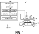
- FIG. 1 is an explanatory view of the coating device according to the embodiment.
- FIG. 1 illustrates a three-dimensional orthogonal coordinate system including a Z-axis for which the vertically upward direction is a positive direction and the vertically downward direction is a negative direction.
- Such orthogonal coordinate systems may also be presented in other drawings used in the description below.
- the same components as those of a coating device 1 illustrated in FIG. 1 are denoted by the same reference numerals, and descriptions thereof will be omitted or simplified.
- the coating device 1 includes a head 10, a wiper 14, a robot 20, and a control device 40.
- the head 10 is fixed to the robot 20.
- the head 10 moves in response to movement of the robot 20 controlled by the control device 40.
- the head 10 coats a to-be-coated object 30 by depositing a coating material discharged from a plurality of discharge holes 11 located on a nozzle surface 12 onto a surface of the to-be-coated object 30 facing the nozzle surface 12.
- the coating material is supplied to the head 10 from a tank (not illustrated).
- the head 10 discharges the coating material supplied from the tank.
- the coating material is a mixture containing a volatile component and a nonvolatile component, and has fluidity.
- the tank may be a reservoir (not illustrated) housed in the head 10.
- the volatile component is, for example, water, organic solvent, or alcohol, and adjusts the physical properties such as viscosity and surface tension of the coating material.
- the nonvolatile component contains, for example, a pigment, a resin material, and an additive.
- the pigment includes one or more colored pigments used depending on a desired coating color.
- the resin material is deposited on the to-be-coated object 30 and forms a film.
- the additive is a functional material that is added, for example for purposes of weather resistance and the like.
- the coating material supplied to the discharge holes 11 is prepared such that a desired coating color is expressed by mixing a plurality of colored pigments or coating materials at predetermined proportions.
- the wiper 14 wipes the nozzle surface 12 of the head 10.
- the wiper 14 is an example of the wiping mechanism.
- the wiper 14 is supported by a support member (not illustrated), and is disposed near the robot 20.
- the wiper 14 is an elastic member having a predetermined hardness.
- the wiper 14 has a hardness between a nonvolatile component contained in the coating material attached to the nozzle surface 12 and the plurality of discharge holes 11 provided in the nozzle surface 12.
- the nonvolatile component contained in the coating material attached to the nozzle surface 12 can be effectively removed, and deformation of the plurality of discharge holes 11 due to wear of the nozzle surface 12 can be suppressed, and thus durability of the head 10 can be improved.
- the hardness of the plurality of discharge holes 11 provided in the nozzle surface 12 may be measured by measuring hardness of, for example, a nozzle plate serving as a member forming the nozzle surface 12.
- the wiper 14 may be formed by wrapping a flexible material such as a woven fabric, a non-woven fabric or a paper around an elastic member. The wiper 14 is pressed against the nozzle surface 12 at a pressure within a predetermined range. When the head 10 is moved in a certain direction while maintaining this state, the coating material, in particular the nonvolatile component such as a pigment and a resin material, attached to the nozzle surface 12 is wiped from the nozzle surface 12.
- the wiper 14 may be a so-called wet wiper containing an affinity component having affinity for the nonvolatile component attached to the nozzle surface 12.
- affinity is referred to as a property of reducing adhesiveness to the nozzle surface 12 by, for example, swelling, dispersion, dissolution, or the like.
- the affinity component having such affinity includes, for example, water, organic solvent, alcohol, oil, and the like, and when the affinity component has volatility, it is possible to suppress a reduction in the coating quality due to a residue of the affinity component on the nozzle surface 12.
- the robot 20 holds the head 10.
- the robot 20 is, for example, a six-axis articulated robot.
- the robot 20 includes a plurality of arms 21 with the head 10 fixed to a tip of the plurality of arms 21.
- the robot 20 is fixed to a floor, a wall, a ceiling, or the like.
- the control device 40 controls the coating device 1.
- the control device 40 includes a controller 41 configured to control the coating device 1, and a storage unit 45.
- the controller 41 includes a discharge controller 42 and an operation controller 43.
- the discharge controller 42 controls the head 10 based on configuration information stored in the storage unit 45, and discharges the coating material from the plurality of discharge holes 11 toward the to-be-coated object 30.
- the operation controller 43 controls operations of the plurality of arms 21 based on the configuration information stored in the storage unit 45, and controls movement of the head 10 via the arms 21.
- the distance between the head 10 and the to-be-coated object 30 is maintained at, for example, approximately from 0.5 to 14 mm.
- the operation controller 43 controls operations of the plurality of arms 21 based on the position information of the wiper 14 stored in the storage unit 45, and relatively moves the head 10 with respect to the wiper 14 to wipe the nozzle surface 12. Note that the detailed movement of the head 10 when the nozzle surface 12 is wiped by the wiper 14 will be described later.
- the storage unit 45 stores configuration information for various types of controls.
- the storage unit 45 stores information related to discharge control of the coating material by the head 10. Further, the storage unit 45 stores information related to the operation control of the plurality of arms 21. Furthermore, the storage unit 45 stores position information of the wiper 14. Note that the storage unit 45 may store data input by the user's instruction operation using a terminal apparatus (not illustrated) as instruction data for operating the robot 20.
- the to-be-coated object 30 is, for example, a vehicle body.
- the to-be-coated object 30 is placed on a conveying device (not illustrated), and is carried in and out.
- the coating device 1 according to an embodiment coats the to-be-coated object 30 in a state where the conveying device is stopped. Note that the coating device 1 may coat the to-be-coated object 30 while the to-be-coated object 30 is being repeatedly conveyed and stopped, or may coat the to-be-coated object 30 while the to-be-coated object 30 is being conveyed.
- the degree of freedom of movement of the head 10 is small, and when the nozzle surface 12 is wiped, the wiper 14 is moved with respect to the head 10.
- the head 10 is fixed to the robot 20, and thus the nozzle surface 12 can be wiped by moving the head 10 with respect to the wiper 14 fixed in the vicinity of the robot 20 in accordance with the degree of freedom of the arm 21.
- a dedicated mechanism for moving the wiper 14 toward the head 10 is unnecessary, and the configuration can be simplified.
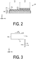
- FIG. 2 is a cross-sectional view illustrating an example of a to-be-coated object that was coated.
- the to-be-coated object 30 illustrated in FIG. 2 includes a base member 31, a primer layer 32, and a first coating layer 33.
- the base member 31 is, for example, a steel plate processed into a predetermined shape, and is subjected to an electrodeposition process as necessary to impart rust resistance thereto.
- the primer layer 32 is provided for imparting weather resistance, color development, and peeling resistance, for example.
- the first coating layer 33 is, for example, a base layer that has smoothness and weather resistance and imparts a desired coating color.
- a surface of the first coating layer 33 serves as a to-be-coated surface 30a to be coated by the coating device 1 according to the embodiment.
- a second coating layer 34 is located on the first coating layer 33 serving as the to-be-coated surface 30a.
- the second coating layer 34 is located so as to cover a portion of the first coating layer 33 with a coating material having a coating color different from that of the first coating layer 33.
- the to-be-coated object 30 becomes a coated body 38 that is coated in a so-called two tone color in which a region 36 where the second coating layer 34 is located and a region 35 where the first coating layer 33 is exposed without the second coating layer 34 being located are aligned with an end portion 37 of the second coating layer 34 as a boundary.
- the coating device 1 has been described such that the second coating layer 34 is located on the to-be-coated surface 30a on the first coating layer 33, but the present invention is not limited thereto, and the coating device 1 may be applied, for example, when the first coating layer 33 is located on a coated surface 32a on the primer layer 32.
- the coated body 38 is not limited to the example illustrated in FIG. 2 .
- a coating layer (not illustrated) may be located on the surfaces of the regions 35 and 36.
- the second coating layer 34 need not be included, and only the first coating layer 33 may be included, and the second coating layer 34 may be located on the entire surface of the first coating layer 33.
- the to-be-coated object 30 or the coated body 38 may further include one or a plurality of layers (not illustrated).
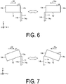
- FIG. 3 is a view illustrating an arrangement example of a head and a wiper included in a coating device according to a first embodiment.
- the operation controller 43 (refer to FIG. 1 ) operates the arm 21 (refer to FIG. 1 ) to move the head 10 relative to the wiper 14.
- the head 10 is disposed such that a first surface 10a located along the XY plane intersecting the Z axis with respect to the wiper 14 disposed along the Z axis direction and serving as one end surface of the head 10 is in contact with or close proximity to the wiper 14.
- the head 10 disposed in this manner is moved in a direction 50 along the Y axis positive direction such that the nozzle surface 12 receives a predetermined pressing force from a second surface 14b of the wiper 14 from the first surface 10a side of the head 10 to a second surface 10b side serving as another end surface, and thus the nozzle surface 12 is wiped by the wiper 14.
- the series of operations described above may be continuously performed after the end of the coating operation, or the arm 21 (refer to FIG. 1 ) may be temporarily stationary before the operation of wiping the nozzle surface 12.
- the arm 21 is temporarily stationary before the wiping operation, position shift of the head 10 due to the movement of the arm 21 accompanied by, for example, vibration or oscillation is reduced, and accuracy of the wiping operation is improved.
- the term "stationary" used herein is not limited to a completely stopped state, and includes, for example, a state in which the vibration or oscillation is attenuated to within a predetermined allowable range.
- the term "before the operation of wiping the nozzle surface 12" is not limited to before the wiper 14 and the nozzle surface 12 are brought into contact with each other, and may be, for example, after the wiper 14 and the nozzle surface 12 are brought into contact with each other and before the head 10 is moved.
- FIG. 4 is a view illustrating an arrangement example of a head and a wiper included in a coating device according to a second embodiment.
- the example illustrated in FIG. 4 differs from the coating device according to the first embodiment illustrated in FIG. 3 in that the nozzle surface 12 of the head 10 is inclined by an angle ⁇ 1 with respect to the XY plane.
- the head 10 disposed so as to be inclined such that the nozzle surface 12 faces the wiper 14 side in this manner is moved in the direction 50 along the Y axis positive direction, and thus the nozzle surface 12 is wiped by the wiper 14 from the first surface 10a side toward the second surface 10b side.
- the wiper 14 is compressed or deflected toward a first surface 14a of the wiper 14 in accordance with its hardness or other characteristics, and thus the nozzle surface 12 receives a predetermined pressing force from the second surface 14b of the wiper 14.
- the angle ⁇ 1 of the nozzle surface 12 with respect to the XY plane can be, for example, 10°or more and 35° or less. In a case where the angle ⁇ 1 is less than 10°, the effect of canceling out the position shift of the head 10 may not be exhibited. Furthermore, in a case where the angle ⁇ 1 exceeds 35°, the amount of change of the wiper 14 increases, and the wiper 14 may be easily damaged.
- FIG. 5 is a view illustrating an arrangement example of a head and a wiper included in a coating device according to a variation of the second embodiment.
- the example illustrated in FIG. 5 differs from the coating device according to the second embodiment illustrated in FIG. 4 in that the direction 50 in which the head 10 moves is along the nozzle surface 12 inclined by an angle ⁇ 2 with respect to the XY plane. Also in the case where the direction 50 is inclined in this manner, similarly to the coating device according to the second embodiment, for example, it is possible to reduce the possibility of damage to the nozzle surface 12 by canceling out the position shift of the head 10 with respect to the wiper 14.
- the angle ⁇ 2 of the nozzle surface 12 with respect to the XY plane can be, for example, 10° or more and 35° or less. In a case where the angle ⁇ 2 is less than 10°, the effect of canceling out the position shift of the head 10 may not be exhibited. In a case where the angle ⁇ 2 exceeds 35°, the pressing force due to the wiper 14 is difficult to be transferred to the nozzle surface 12, and a wiping failure of the nozzle surface 12 may occur.
- FIG. 6 is a view illustrating an arrangement example of a head and a wiper included in a coating device according to a third embodiment.
- the example illustrated in FIG. 6 differs from the coating device according to the first embodiment illustrated in FIG. 3 in that the nozzle surface 12 can be wiped in both directions of the direction 50 and a direction 50a facing each other along the Y axis direction.
- the nozzle surface 12 is wiped by the second surface 14b of the wiper 14 from the first surface 10a side toward the second surface 10b side. Furthermore, while the head 10 is moved in the direction 50a along the Y axis negative direction, the nozzle surface 12 is wiped by the first surface 14a of the wiper 14 from the second surface 10b side toward the first surface 10a side.
- the nozzle surface 12 can be wiped in both directions of the direction 50 and the direction 50a as described above, and thus the wiping performance by the wiper 14 is improved.
- the wiping performance by the wiper 14 is improved.
- FIG. 7 is a view illustrating an arrangement example of a head and a wiper included in a coating device according to a variation of the third embodiment.
- the example illustrated in FIG. 7 differs from the coating device according to the second embodiment illustrated in FIG. 4 in that the nozzle surface 12 can be wiped in both directions of the direction 50 and the direction 50a facing each other along the Y axis direction.
- the head 10 while the head 10 is moved in the direction 50 along the Y axis positive direction in a posture inclined such that the nozzle surface 12 faces the wiper 14 side, the nozzle surface 12 is wiped by the second surface 14b of the wiper 14 from the first surface 10a side toward the second surface 10b side. Furthermore, the head 10 changes the posture of the nozzle surface 12 such that the nozzle surface 12 faces the wiper 14 side and while the head 10 is moved in the direction 50a along the Y axis negative direction, the nozzle surface 12 is wiped by the first surface 14a of the wiper 14 from the second surface 10b side toward the first surface 10a side.
- the nozzle surface 12 can be wiped in both directions of the direction 50 and the direction 50a as described above, and thus the wiping performance by the wiper 14 is improved. Furthermore, by changing an inclination of the nozzle surface 12 in both directions of the direction 50 and the direction 50a, the wiping performance of the nozzle surface 12 is improved, and for example, the coating material remaining in the nozzle surface 12 is reduced.
- the head 10 has been described as moving along the directions 50 and 50a along the Y axis component, but the embodiment is not limited thereto, and, for example, the head 10 may be moved in a direction along the nozzle surface 12 as illustrated in FIG. 5 .
- FIG. 8 is a view illustrating an arrangement example of a head and a wiper included in a coating device according to a fourth embodiment.
- the direction 50 in which the head 10 is moved when the nozzle surface 12 is wiped, and the direction 51 in which the head 10 is moved when the coating material 13 is discharged from the plurality of discharge holes 11 and the surface of the to-be-coated object 30 facing the nozzle surface 12 is coated are parallel.
- the controller 41 operation controller 43
- the direction 50 in which the head 10 is moved when the nozzle surface 12 is wiped may be a direction facing the direction 51.
- FIG. 9 is a view illustrating an arrangement example of a head and a wiper included in a coating device according to a variation of the fourth embodiment.
- the direction 50 in which the head 10 is moved when the nozzle surface 12 is wiped, and the direction 51 in which the head 10 is moved when the coating material 13 is discharged from the plurality of discharge holes 11 and the surface of the to-be-coated object 30 facing the nozzle surface 12 is coated intersect each other.
- the direction 50 is a direction along the Y axis
- the direction 51 is a direction along the X axis intersecting the Y axis.
- the nozzle surface 12 can be wiped in the middle of switching the moving direction of the head 10, in the head 10 that performs coating while reciprocating between one end side and the other end side of the coating material 13, and, for example, the coating time can be shortened by reducing the movement distance of the head 10.
- FIG. 10 is a view illustrating an arrangement example of a head and a wiper included in a coating device according to a fifth embodiment.
- the wiper 14 is supported by a suspension 18 serving as a buffer mechanism.
- the suspension 18 adjusts the height of the wiper 14, in other words, the length in the Z axis direction in accordance with the pressing force received by the wiper 14 from the nozzle surface 12, thus buffering the pressing force received by the nozzle surface 12 from the wiper 14.
- the suspension 18 for supporting the wiper 14 it is possible to absorb a difference of the pressing force received by the nozzle surface 12 from the wiper 14 in accordance with, for example, the position shift and the variation in the movement speed of the head 10.
- FIG. 11 is a view illustrating an arrangement example of a head and a wiper included in a coating device according to a sixth embodiment.
- a plurality of wipers 14 and 15 having different characteristics are included.
- the wiper 14 is a so-called wet wiper containing an affinity component for the nonvolatile component contained in the coating material
- the wiper 15 is a so-called dry wiper not containing the affinity component or having a smaller content of affinity component than that of the wiper 14.
- the wiper 14 is an example of a first wiper
- the wiper 15 is an example of a second wiper.
- the nozzle surface 12 is sequentially wiped from the first surface 10a side toward the second surface 10b side by the wipers 14 and 15.
- the plurality of wipers 14 and 15 having different characteristics such that specifically the nozzle surface 12 is wiped by the wet wiper and then the dry wiper, a decrease in the coating quality due to the affinity component remaining in the nozzle surface 12 can be prevented, for example.
- the wipers 14 and 15 are configured to be arranged in parallel along the direction 50 in which the nozzle surface 12 moves, but there is no restriction on the arrangement as long as the wipers 14 and 15 are included. Nevertheless, in a case where the wipers 14 and 15 are arranged in parallel as illustrated in FIG. 11 , the time required for the wiping of the nozzle surface 12 can be shortened for example.
- FIG. 12 is a view illustrating an arrangement example of a head and a wiper included in a coating device according to a seventh embodiment.
- a plurality of wipers 14 to 16 having different characteristics and an elevating mechanism 19 are included.
- the wipers 14 to 16 are arranged in parallel along the Y axis direction.
- the wipers 14 and 16 are the wet wipers, and the wiper 15 is the dry wiper.
- the wipers 14 to 16 are examples of the first to third wipers, respectively.
- the elevating mechanism 19 is configured to allow the wipers 14 to 16 to elevate in accordance with the control of the controller 41.
- the elevating mechanism 19 allows the wiper 16 to operate so as to be lower than the height of the wiper 15 in the Z direction and allows the wiper 14 to operate so as to match the height of the wiper 15 in the Z direction.
- the nozzle surface 12 is sequentially wiped by the wiper 14 and the wiper 15 from the first surface 10a side toward the second surface 10b side, but is not wiped by the wiper 16.
- the elevating mechanism 19 allows the wiper 16 to operate so as to match the height of the wiper 15 in the Z direction and allows the wiper 14 to operate so as to be lower than the height of the wiper 15 in the Z direction.
- the nozzle surface 12 is sequentially wiped by the wiper 16 and the wiper 15 from the second surface 10b side toward the first surface 10a side, but is not wiped by the wiper 14.
- the nozzle surface 12 can be wiped in both directions of the direction 50 and the direction 50a and thus the wiping performance by the wipers 14 to 16 are improved.
- FIG. 13 is a view illustrating an arrangement example of a head and a wiper included in a coating device according to a variation of the seventh embodiment.
- a plurality of wipers 15, 14. and 17 having different characteristics and the elevating mechanism 19 are included.
- the wipers 15, 14 and 17 are disposed in order along the Y axis direction.
- the wiper 14 is the wet wiper, and the wipers 15 and 17 are the dry wipers.
- the wipers 14, 15, and 17 are examples of the first wiper, the second wiper, and a fourth wiper, respectively.
- the elevating mechanism 19 is configured to allow the wipers 15 and 17 to elevate in accordance with the control of the controller 41.
- the elevating mechanism 19 allows the wiper 15 to operate so as to be lower than the height of the wiper 14 in the Z direction and allows the wiper 17 to operate so as to match the height of the wiper 14 in the Z direction.
- the nozzle surface 12 is sequentially wiped by the wiper 14 and the wiper 17 from the first surface 10a side toward the second surface 10b side, but is not wiped by the wiper 15.
- the elevating mechanism 19 allows the wiper 15 to operate so as to match the height of the wiper 14 in the Z direction and allows the wiper 17 to operate so as to be lower than the height of the wiper 14 in the Z direction.
- the nozzle surface 12 is sequentially wiped by the wiper 14 and the wiper 15 from the second surface 10b side toward the first surface 10a side, but is not wiped by the wiper 17.
- the nozzle surface 12 can be wiped in both directions of the direction 50 and the direction 50a and thus the wiping performance by the wipers 15, 14 and 17 are improved.
- FIG. 14 is a view illustrating an arrangement example of a head and a wiper included in a coating device according to an eighth embodiment.
- a plurality of wipers 14 to 16 having different characteristics are included.
- the wipers 14 to 16 are arranged in parallel along the Y axis direction. Furthermore, the wiper 15 protrudes with respect to the wipers 14 and 16.
- the wipers 14 and 16 are the wet wipers, and the wiper 15 is the dry wiper.
- the wipers 14 to 16 are examples of the first to third wipers, respectively.
- the nozzle surface 12 is sequentially wiped by the wiper 14 and the wiper 15 from the first surface 10a side toward the second surface 10b side, but is not wiped by the wiper 16.
- the nozzle surface 12 is sequentially wiped by the wiper 16 and the wiper 15 from the second surface 10b side toward the first surface 10a side, but is not wiped by the wiper 14.
- the nozzle surface 12 can be wiped in both directions of the direction 50 and the direction 50a and thus the wiping performance by the wipers 14 to 16 are improved.
- the head 10 may be moved in the direction along the nozzle surface 12, and the head 10 may be moved while changing the inclination of the nozzle surface 12 with respect to the wiper 14.
- the arm 21 (refer to FIG. 1 ) adjusts the angle of the head 10 as appropriate, and thus the wipers 14 to 16 can be selectively brought into contact.
- FIG. 15 is an explanatory view of a coating device according to a first variation of an embodiment.
- the example illustrated in FIG. 15 differs from the coating device 1 according to the embodiment in that the wiper 14 includes a robot 20A fixed to the arm 21.
- the wiper 14 is fixed to the arm 21, and thus the nozzle surface 12 can be wiped by moving both the head 10 and the wiper 14 relative to each other.
- the time required for the wiping of the nozzle surface 12 can be shortened.
- a loss of time can be reduced. Frequent wiping also has the advantage of improving coating quality.
- FIG. 16 is an explanatory view of a coating device according to a second variation of an embodiment.
- a coating device 1A illustrated in FIG. 16 differs from the coating device 1 according to each of the above-described embodiments and variations in that a wiping unit 114 serving as an example of the wiping mechanism is included instead of the wiper 14.
- FIG. 17 is an explanatory view of the wiping unit illustrated in FIG. 16 .
- the wiping unit 114 includes a pressure roller 115, an unwinding roller 116, a winding roller 117, and a wiping web 120.
- the unwinding roller 116 unwinds the wiping web 120.
- the unwinding roller 116 unwinds a wiping web 120a before a wiping process for the wiping of the head 10 by the wiping unit 114.
- the pressure roller 115 presses the wiping web 120 against the nozzle surface 12 of the head 10.
- the pressure roller 115 is located between the unwinding roller 116 and the winding roller 117.
- the pressure roller 115 presses the wiping web 120a before wiping, which is unwound from the unwinding roller 116, against the nozzle surface 12 of the head 10.
- the pressure roller 115 may be rotated or may not be rotated following movement of the wiping web 120.
- the winding roller 117 winds the wiping web 120 unwound from the unwinding roller 116.
- the winding roller 117 winds a wiping web 120b after the wiping, which is passed through the pressure roller 115.
- the wiping web 120 may be a flexible material such as, a woven fabric, a nonwoven fabric, a paper, or the like.
- the wiping web 120 is pressed against the nozzle surface 12 at a pressure within a predetermined range by the pressure roller 115.
- the coating material in particular the nonvolatile component such as a pigment and a resin material, attached to the nozzle surface 12 is wiped from the nozzle surface 12.
- the wiping web 120 may contain the affinity component having affinity for the nonvolatile component attached to the nozzle surface 12.
- affinity is referred to as a property of reducing adhesiveness to the nozzle surface 12 by, for example, swelling, dispersion, dissolution, or the like.
- the affinity component having such affinity includes, for example, water, organic solvent, alcohol, oil, and the like, and when the affinity component has volatility, it is possible to suppress a reduction in the coating quality due to a residue of the affinity component on the nozzle surface 12.
- the wiping unit 114 may be fixed to the arm 21.
- the nozzle surface 12 can be wiped by moving both the head 10 and the wiping unit 114 relative to each other.
- the time required for the wiping of the nozzle surface 12 can be shortened.
- a loss of time can be reduced. Frequent wiping also has the advantage of improving coating quality.
- the driving of the wiping unit 114 may also be controlled by the control device 40.
- the control device 40 may control, for example, a winding speed of the wiping web 120 by driving the winding roller 117 and/or the unwinding roller 116, and/or an amount of pressing in which the wiping web 120 is pressed against the nozzle surface 12 via the pressure roller 115.
- the wiping unit 114 may be controlled by a control mechanism (not illustrated) different from the control device 40.
- the coating device 1 including the head 10 configured to discharge a single color coating material was described.
- robots 20 respectively holding heads 10 for discharging coating materials of basic colors such as magenta (M), yellow (Y), cyan (C), and black (K) may be included.
- the example is illustrated in which the nozzle surface 12 is wiped by the wiper 14 extending toward the Z axis positive direction, but the embodiment is not limited thereto, and for example, the nozzle surface 12 may be wiped by the wiper 14 extending toward the Z axis negative direction, or the nozzle surface 12 may be wiped by the wiper 14 located along the X axis direction or the Y axis direction intersecting the Z axis direction. Furthermore, the nozzle surface 12 may be wiped by the wiper 14 located obliquely with respect to the Z axis.
- the wiping unit 114 presses the wiping web 120 toward the Z axis positive direction side, but the embodiment is not limited thereto, and for example, the wiping web 120 may be pressed toward the Z axis negative direction, and the wiping web 120 may be pressed in the direction along X axis direction or the Y axis direction intersecting the Z axis direction. Furthermore, the wiping unit 114 may press the wiping web 120 in a direction obliquely directed with respect to the Z axis.
- the example is illustrated in which the elastic member having the predetermined hardness is used as the wiper 14, but the embodiment is not limited thereto, and the wiper 14 of non-contact type may be used.
- the wiper 14 of non-contact type can include a hollow tubular member.
- the wiper 14 of non-contact type can wipe the nozzle surface 12 in a non-contact state by ejecting air from the inside the tube.
- the coating device 1 includes the head 10, the wiping mechanism (the wiper 14 and/or the wiping unit 114), the arm 21, and the controller 41.
- the head 10 includes the nozzle surface 12 for discharging the coating material.
- the wiping mechanism wipes the nozzle surface 12.
- the arm 21 holds the head 10.
- the controller 41 controls the movement of the head 10 via the arm 21.
- the controller 41 relatively moves the head 10 with respect to the wiping mechanism to wipe the nozzle surface 12.
- the configuration can be simplified.
Landscapes
- Engineering & Computer Science (AREA)
- Robotics (AREA)
- Coating Apparatus (AREA)
- Mechanical Engineering (AREA)
- Ink Jet (AREA)
Abstract
Description
- Disclosed embodiments relate to a coating device and a wiping method.
- A coating device using an inkjet method is known. A head for discharging a coating material and a wiper for removing the coating material attached to the head are mounted on such a coating device using an inkjet method. The coating device operates so as to wipe one side of the head for discharging the coating material by a dedicated mechanism for moving the wiper to remove the coating material attached to the head.
-
- Patent Document 1:
JP 2004-160801 A - Patent Document 2:
JP 2004-337770 A - A coating device according to one aspect of an embodiment includes a head, a wiping mechanism, an arm, and a controller. The head includes a nozzle surface for discharging a coating material. The wiping mechanism wipes the nozzle surface. The arm holds the head. The controller controls movement of the head via the arm. The controller relatively moves the head with respect to the wiping mechanism to wipe the nozzle surface.
-
-
FIG. 1 is an explanatory view of a coating device according to an embodiment. -
FIG. 2 is a cross-sectional view illustrating an example of a to-be-coated object that was coated. -
FIG. 3 is a view illustrating an arrangement example of a head and a wiper included in a coating device according to a first embodiment. -
FIG. 4 is a view illustrating an arrangement example of a head and a wiper included in a coating device according to a second embodiment. -
FIG. 5 is a view illustrating an arrangement example of a head and a wiper included in a coating device according to a variation of the second embodiment. -
FIG. 6 is a view illustrating an arrangement example of a head and a wiper included in a coating device according to a third embodiment. -
FIG. 7 is a view illustrating an arrangement example of a head and a wiper included in a coating device according to a variation of the third embodiment. -
FIG. 8 is a view illustrating an arrangement example of a head and a wiper included in a coating device according to a fourth embodiment. -
FIG. 9 is a view illustrating an arrangement example of a head and a wiper included in a coating device according to a variation of the fourth embodiment. -
FIG. 10 is a view illustrating an arrangement example of a head and a wiper included in a coating device according to a fifth embodiment. -
FIG. 11 is a view illustrating an arrangement example of a head and a wiper included in a coating device according to a sixth embodiment. -
FIG. 12 is a view illustrating an arrangement example of a head and a wiper included in a coating device according to a seventh embodiment. -
FIG. 13 is a view illustrating an arrangement example of a head and a wiper included in a coating device according to a variation of the seventh embodiment. -
FIG. 14 is a view illustrating an arrangement example of a head and a wiper included in a coating device according to a eighth embodiment. -
FIG. 15 is an explanatory view of a coating device according to a first variation of an embodiment. -
FIG. 16 is an explanatory view of a coating device according to a second variation of an embodiment. -
FIG. 17 is an explanatory view of a wiping unit illustrated inFIG. 16 . - Embodiments of a coating device and a wiping method disclosed in the present application will be described in detail below with reference to the accompanying drawings. Note that the present invention is not limited to the embodiments that will be described below.
- First, with reference to
FIG. 1 , a description will be given of an overview of a coating device according to an embodiment.FIG. 1 is an explanatory view of the coating device according to the embodiment. For the sake of clarity,FIG. 1 illustrates a three-dimensional orthogonal coordinate system including a Z-axis for which the vertically upward direction is a positive direction and the vertically downward direction is a negative direction. Such orthogonal coordinate systems may also be presented in other drawings used in the description below. The same components as those of acoating device 1 illustrated inFIG. 1 are denoted by the same reference numerals, and descriptions thereof will be omitted or simplified. - As illustrated in
FIG. 1 , thecoating device 1 includes ahead 10, awiper 14, arobot 20, and acontrol device 40. - The
head 10 is fixed to therobot 20. Thehead 10 moves in response to movement of therobot 20 controlled by thecontrol device 40. - The
head 10 coats a to-be-coatedobject 30 by depositing a coating material discharged from a plurality ofdischarge holes 11 located on anozzle surface 12 onto a surface of the to-be-coatedobject 30 facing thenozzle surface 12. - The coating material is supplied to the
head 10 from a tank (not illustrated). Thehead 10 discharges the coating material supplied from the tank. The coating material is a mixture containing a volatile component and a nonvolatile component, and has fluidity. Note that the tank may be a reservoir (not illustrated) housed in thehead 10. - The volatile component is, for example, water, organic solvent, or alcohol, and adjusts the physical properties such as viscosity and surface tension of the coating material. The nonvolatile component contains, for example, a pigment, a resin material, and an additive. The pigment includes one or more colored pigments used depending on a desired coating color. The resin material is deposited on the to-
be-coated object 30 and forms a film. The additive is a functional material that is added, for example for purposes of weather resistance and the like. - Note that the coating material supplied to the
discharge holes 11 is prepared such that a desired coating color is expressed by mixing a plurality of colored pigments or coating materials at predetermined proportions. - The
wiper 14 wipes thenozzle surface 12 of thehead 10. Thewiper 14 is an example of the wiping mechanism. Thewiper 14 is supported by a support member (not illustrated), and is disposed near therobot 20. Thewiper 14 is an elastic member having a predetermined hardness. Specifically, thewiper 14 has a hardness between a nonvolatile component contained in the coating material attached to thenozzle surface 12 and the plurality ofdischarge holes 11 provided in thenozzle surface 12. Thus, the nonvolatile component contained in the coating material attached to thenozzle surface 12 can be effectively removed, and deformation of the plurality ofdischarge holes 11 due to wear of thenozzle surface 12 can be suppressed, and thus durability of thehead 10 can be improved. Note that the hardness of the plurality ofdischarge holes 11 provided in thenozzle surface 12 may be measured by measuring hardness of, for example, a nozzle plate serving as a member forming thenozzle surface 12. - Furthermore, the
wiper 14 may be formed by wrapping a flexible material such as a woven fabric, a non-woven fabric or a paper around an elastic member. Thewiper 14 is pressed against thenozzle surface 12 at a pressure within a predetermined range. When thehead 10 is moved in a certain direction while maintaining this state, the coating material, in particular the nonvolatile component such as a pigment and a resin material, attached to thenozzle surface 12 is wiped from thenozzle surface 12. - The
wiper 14 may be a so-called wet wiper containing an affinity component having affinity for the nonvolatile component attached to thenozzle surface 12. Here, the term "affinity" is referred to as a property of reducing adhesiveness to thenozzle surface 12 by, for example, swelling, dispersion, dissolution, or the like. When the adhesiveness between thenozzle surface 12 and the nonvolatile component is reduced, the nonvolatile component can be easily wiped. The affinity component having such affinity includes, for example, water, organic solvent, alcohol, oil, and the like, and when the affinity component has volatility, it is possible to suppress a reduction in the coating quality due to a residue of the affinity component on thenozzle surface 12. - The
robot 20 holds thehead 10. Therobot 20 is, for example, a six-axis articulated robot. Therobot 20 includes a plurality ofarms 21 with thehead 10 fixed to a tip of the plurality ofarms 21. Therobot 20 is fixed to a floor, a wall, a ceiling, or the like. - The
control device 40 controls thecoating device 1. Thecontrol device 40 includes a controller 41 configured to control thecoating device 1, and astorage unit 45. The controller 41 includes a discharge controller 42 and anoperation controller 43. - The discharge controller 42 controls the
head 10 based on configuration information stored in thestorage unit 45, and discharges the coating material from the plurality of discharge holes 11 toward the to-be-coated object 30. Theoperation controller 43 controls operations of the plurality ofarms 21 based on the configuration information stored in thestorage unit 45, and controls movement of thehead 10 via thearms 21. The distance between thehead 10 and the to-be-coated object 30 is maintained at, for example, approximately from 0.5 to 14 mm. - The
operation controller 43 controls operations of the plurality ofarms 21 based on the position information of thewiper 14 stored in thestorage unit 45, and relatively moves thehead 10 with respect to thewiper 14 to wipe thenozzle surface 12. Note that the detailed movement of thehead 10 when thenozzle surface 12 is wiped by thewiper 14 will be described later. - The
storage unit 45 stores configuration information for various types of controls. Thestorage unit 45 stores information related to discharge control of the coating material by thehead 10. Further, thestorage unit 45 stores information related to the operation control of the plurality ofarms 21. Furthermore, thestorage unit 45 stores position information of thewiper 14. Note that thestorage unit 45 may store data input by the user's instruction operation using a terminal apparatus (not illustrated) as instruction data for operating therobot 20. - The to-
be-coated object 30 is, for example, a vehicle body. The to-be-coated object 30 is placed on a conveying device (not illustrated), and is carried in and out. Thecoating device 1 according to an embodiment coats the to-be-coated object 30 in a state where the conveying device is stopped. Note that thecoating device 1 may coat the to-be-coated object 30 while the to-be-coated object 30 is being repeatedly conveyed and stopped, or may coat the to-be-coated object 30 while the to-be-coated object 30 is being conveyed. - In a conventional device using the
head 10, the degree of freedom of movement of thehead 10 is small, and when thenozzle surface 12 is wiped, thewiper 14 is moved with respect to thehead 10. Thus, there is room for improvement in terms of simplification of the configuration capable of realizing, for example, miniaturization and cost reduction. In contrast, in thecoating device 1 according to the embodiment, thehead 10 is fixed to therobot 20, and thus thenozzle surface 12 can be wiped by moving thehead 10 with respect to thewiper 14 fixed in the vicinity of therobot 20 in accordance with the degree of freedom of thearm 21. Thus, for example, a dedicated mechanism for moving thewiper 14 toward thehead 10 is unnecessary, and the configuration can be simplified. -
FIG. 2 is a cross-sectional view illustrating an example of a to-be-coated object that was coated. The to-be-coated object 30 illustrated inFIG. 2 includes abase member 31, aprimer layer 32, and afirst coating layer 33. Thebase member 31 is, for example, a steel plate processed into a predetermined shape, and is subjected to an electrodeposition process as necessary to impart rust resistance thereto. Theprimer layer 32 is provided for imparting weather resistance, color development, and peeling resistance, for example. Thefirst coating layer 33 is, for example, a base layer that has smoothness and weather resistance and imparts a desired coating color. A surface of thefirst coating layer 33 serves as a to-be-coated surface 30a to be coated by thecoating device 1 according to the embodiment. - A
second coating layer 34 is located on thefirst coating layer 33 serving as the to-be-coated surface 30a. Thesecond coating layer 34 is located so as to cover a portion of thefirst coating layer 33 with a coating material having a coating color different from that of thefirst coating layer 33. As a result, the to-be-coated object 30 becomes acoated body 38 that is coated in a so-called two tone color in which aregion 36 where thesecond coating layer 34 is located and a region 35 where thefirst coating layer 33 is exposed without thesecond coating layer 34 being located are aligned with anend portion 37 of thesecond coating layer 34 as a boundary. - In the example illustrated in
FIG. 2 , thecoating device 1 has been described such that thesecond coating layer 34 is located on the to-be-coated surface 30a on thefirst coating layer 33, but the present invention is not limited thereto, and thecoating device 1 may be applied, for example, when thefirst coating layer 33 is located on acoated surface 32a on theprimer layer 32. - Note that the
coated body 38 is not limited to the example illustrated inFIG. 2 . For example, a coating layer (not illustrated) may be located on the surfaces of theregions 35 and 36. Further, thesecond coating layer 34 need not be included, and only thefirst coating layer 33 may be included, and thesecond coating layer 34 may be located on the entire surface of thefirst coating layer 33. Further, the to-be-coated object 30 or thecoated body 38 may further include one or a plurality of layers (not illustrated). -
FIG. 3 is a view illustrating an arrangement example of a head and a wiper included in a coating device according to a first embodiment. The operation controller 43 (refer toFIG. 1 ) operates the arm 21 (refer toFIG. 1 ) to move thehead 10 relative to thewiper 14. Specifically, as illustrated inFIG. 3 , thehead 10 is disposed such that afirst surface 10a located along the XY plane intersecting the Z axis with respect to thewiper 14 disposed along the Z axis direction and serving as one end surface of thehead 10 is in contact with or close proximity to thewiper 14. Thehead 10 disposed in this manner is moved in adirection 50 along the Y axis positive direction such that thenozzle surface 12 receives a predetermined pressing force from asecond surface 14b of thewiper 14 from thefirst surface 10a side of thehead 10 to asecond surface 10b side serving as another end surface, and thus thenozzle surface 12 is wiped by thewiper 14. - Note that the series of operations described above may be continuously performed after the end of the coating operation, or the arm 21 (refer to
FIG. 1 ) may be temporarily stationary before the operation of wiping thenozzle surface 12. In a case where thearm 21 is temporarily stationary before the wiping operation, position shift of thehead 10 due to the movement of thearm 21 accompanied by, for example, vibration or oscillation is reduced, and accuracy of the wiping operation is improved. Note that the term "stationary" used herein is not limited to a completely stopped state, and includes, for example, a state in which the vibration or oscillation is attenuated to within a predetermined allowable range. The term "before the operation of wiping thenozzle surface 12" is not limited to before thewiper 14 and thenozzle surface 12 are brought into contact with each other, and may be, for example, after thewiper 14 and thenozzle surface 12 are brought into contact with each other and before thehead 10 is moved. -
FIG. 4 is a view illustrating an arrangement example of a head and a wiper included in a coating device according to a second embodiment. The example illustrated inFIG. 4 differs from the coating device according to the first embodiment illustrated inFIG. 3 in that thenozzle surface 12 of thehead 10 is inclined by an angle θ1 with respect to the XY plane. - The
head 10 disposed so as to be inclined such that thenozzle surface 12 faces thewiper 14 side in this manner is moved in thedirection 50 along the Y axis positive direction, and thus thenozzle surface 12 is wiped by thewiper 14 from thefirst surface 10a side toward thesecond surface 10b side. Thewiper 14 is compressed or deflected toward afirst surface 14a of thewiper 14 in accordance with its hardness or other characteristics, and thus thenozzle surface 12 receives a predetermined pressing force from thesecond surface 14b of thewiper 14. Thus, even in a case where the movement of thehead 10 with respect to thewiper 14 is subjected to be the position shift, it is possible to, for example, reduce the possibility of damage to thenozzle surface 12 by canceling out the position shift by changing an amount of deformation of thewiper 14. - Here, the angle θ1 of the
nozzle surface 12 with respect to the XY plane (the wiper 14) can be, for example, 10°or more and 35° or less. In a case where the angle θ1 is less than 10°, the effect of canceling out the position shift of thehead 10 may not be exhibited. Furthermore, in a case where the angle θ1 exceeds 35°, the amount of change of thewiper 14 increases, and thewiper 14 may be easily damaged. -
FIG. 5 is a view illustrating an arrangement example of a head and a wiper included in a coating device according to a variation of the second embodiment. The example illustrated inFIG. 5 differs from the coating device according to the second embodiment illustrated inFIG. 4 in that thedirection 50 in which thehead 10 moves is along thenozzle surface 12 inclined by an angle θ2 with respect to the XY plane. Also in the case where thedirection 50 is inclined in this manner, similarly to the coating device according to the second embodiment, for example, it is possible to reduce the possibility of damage to thenozzle surface 12 by canceling out the position shift of thehead 10 with respect to thewiper 14. - Here, the angle θ2 of the
nozzle surface 12 with respect to the XY plane (the wiper 14) can be, for example, 10° or more and 35° or less. In a case where the angle θ2 is less than 10°, the effect of canceling out the position shift of thehead 10 may not be exhibited. In a case where the angle θ2 exceeds 35°, the pressing force due to thewiper 14 is difficult to be transferred to thenozzle surface 12, and a wiping failure of thenozzle surface 12 may occur. -
FIG. 6 is a view illustrating an arrangement example of a head and a wiper included in a coating device according to a third embodiment. The example illustrated inFIG. 6 differs from the coating device according to the first embodiment illustrated inFIG. 3 in that thenozzle surface 12 can be wiped in both directions of thedirection 50 and adirection 50a facing each other along the Y axis direction. - In other words, while the
head 10 is moved in thedirection 50 along the Y axis positive direction, thenozzle surface 12 is wiped by thesecond surface 14b of thewiper 14 from thefirst surface 10a side toward thesecond surface 10b side. Furthermore, while thehead 10 is moved in thedirection 50a along the Y axis negative direction, thenozzle surface 12 is wiped by thefirst surface 14a of thewiper 14 from thesecond surface 10b side toward thefirst surface 10a side. - The
nozzle surface 12 can be wiped in both directions of thedirection 50 and thedirection 50a as described above, and thus the wiping performance by thewiper 14 is improved. By wiping from both directions of thedirection 50 and thedirection 50a, for example, deformation of the discharge holes 11 (refer toFIG. 1 ) due to the wear of thenozzle surface 12 can be suppressed, and thus the durability of thehead 10 is improved. -
FIG. 7 is a view illustrating an arrangement example of a head and a wiper included in a coating device according to a variation of the third embodiment. The example illustrated inFIG. 7 differs from the coating device according to the second embodiment illustrated inFIG. 4 in that thenozzle surface 12 can be wiped in both directions of thedirection 50 and thedirection 50a facing each other along the Y axis direction. - In other words, while the
head 10 is moved in thedirection 50 along the Y axis positive direction in a posture inclined such that thenozzle surface 12 faces thewiper 14 side, thenozzle surface 12 is wiped by thesecond surface 14b of thewiper 14 from thefirst surface 10a side toward thesecond surface 10b side. Furthermore, thehead 10 changes the posture of thenozzle surface 12 such that thenozzle surface 12 faces thewiper 14 side and while thehead 10 is moved in thedirection 50a along the Y axis negative direction, thenozzle surface 12 is wiped by thefirst surface 14a of thewiper 14 from thesecond surface 10b side toward thefirst surface 10a side. - The
nozzle surface 12 can be wiped in both directions of thedirection 50 and thedirection 50a as described above, and thus the wiping performance by thewiper 14 is improved. Furthermore, by changing an inclination of thenozzle surface 12 in both directions of thedirection 50 and thedirection 50a, the wiping performance of thenozzle surface 12 is improved, and for example, the coating material remaining in thenozzle surface 12 is reduced. - Note that in the example illustrated in
FIG. 7 , thehead 10 has been described as moving along thedirections head 10 may be moved in a direction along thenozzle surface 12 as illustrated inFIG. 5 . -
FIG. 8 is a view illustrating an arrangement example of a head and a wiper included in a coating device according to a fourth embodiment. In the example illustrated inFIG. 8 , thedirection 50 in which thehead 10 is moved when thenozzle surface 12 is wiped, and thedirection 51 in which thehead 10 is moved when thecoating material 13 is discharged from the plurality of discharge holes 11 and the surface of the to-be-coated object 30 facing thenozzle surface 12 is coated are parallel. - As described above, by wiping the
nozzle surface 12 by moving thehead 10 in thedirection 50 along thedirection 51 which is the movement direction of thehead 10 when coating the to-be-coated object 30, for example, posture control of thehead 10 using the robot 20 (refer toFIG. 1 ) by the controller 41 (operation controller 43) is simplified. Note that thedirection 50 in which thehead 10 is moved when thenozzle surface 12 is wiped may be a direction facing thedirection 51. -
FIG. 9 is a view illustrating an arrangement example of a head and a wiper included in a coating device according to a variation of the fourth embodiment. In the example illustrated inFIG. 9 , thedirection 50 in which thehead 10 is moved when thenozzle surface 12 is wiped, and thedirection 51 in which thehead 10 is moved when thecoating material 13 is discharged from the plurality of discharge holes 11 and the surface of the to-be-coated object 30 facing thenozzle surface 12 is coated intersect each other. Specifically, thedirection 50 is a direction along the Y axis, and thedirection 51 is a direction along the X axis intersecting the Y axis. - As described above, by wiping the
nozzle surface 12 by moving thehead 10 in thedirection 50 intersecting thedirection 51 which is the movement direction of thehead 10 when coating the to-be-coated object 30, for example, thenozzle surface 12 can be wiped in the middle of switching the moving direction of thehead 10, in thehead 10 that performs coating while reciprocating between one end side and the other end side of thecoating material 13, and, for example, the coating time can be shortened by reducing the movement distance of thehead 10. -
FIG. 10 is a view illustrating an arrangement example of a head and a wiper included in a coating device according to a fifth embodiment. In the example illustrated inFIG. 10 , thewiper 14 is supported by asuspension 18 serving as a buffer mechanism. Thesuspension 18 adjusts the height of thewiper 14, in other words, the length in the Z axis direction in accordance with the pressing force received by thewiper 14 from thenozzle surface 12, thus buffering the pressing force received by thenozzle surface 12 from thewiper 14. As described above, by including thesuspension 18 for supporting thewiper 14, it is possible to absorb a difference of the pressing force received by thenozzle surface 12 from thewiper 14 in accordance with, for example, the position shift and the variation in the movement speed of thehead 10. -
FIG. 11 is a view illustrating an arrangement example of a head and a wiper included in a coating device according to a sixth embodiment. In the example illustrated inFIG. 11 , a plurality ofwipers - The
wiper 14 is a so-called wet wiper containing an affinity component for the nonvolatile component contained in the coating material, and thewiper 15 is a so-called dry wiper not containing the affinity component or having a smaller content of affinity component than that of thewiper 14. Thewiper 14 is an example of a first wiper, and thewiper 15 is an example of a second wiper. - While the
head 10 is moved in thedirection 50 along the Y axis positive direction, thenozzle surface 12 is sequentially wiped from thefirst surface 10a side toward thesecond surface 10b side by thewipers wipers nozzle surface 12 is wiped by the wet wiper and then the dry wiper, a decrease in the coating quality due to the affinity component remaining in thenozzle surface 12 can be prevented, for example. - Note that in the example illustrated in
FIG. 11 , thewipers direction 50 in which thenozzle surface 12 moves, but there is no restriction on the arrangement as long as thewipers wipers FIG. 11 , the time required for the wiping of thenozzle surface 12 can be shortened for example. -
FIG. 12 is a view illustrating an arrangement example of a head and a wiper included in a coating device according to a seventh embodiment. In the example illustrated inFIG. 12 , a plurality ofwipers 14 to 16 having different characteristics and an elevatingmechanism 19 are included. - The
wipers 14 to 16 are arranged in parallel along the Y axis direction. Thewipers wiper 15 is the dry wiper. Thewipers 14 to 16 are examples of the first to third wipers, respectively. Further, the elevatingmechanism 19 is configured to allow thewipers 14 to 16 to elevate in accordance with the control of the controller 41. - While the
head 10 is moved in thedirection 50 along the Y axis positive direction, the elevatingmechanism 19 allows thewiper 16 to operate so as to be lower than the height of thewiper 15 in the Z direction and allows thewiper 14 to operate so as to match the height of thewiper 15 in the Z direction. With the operation of the elevatingmechanism 19, thenozzle surface 12 is sequentially wiped by thewiper 14 and thewiper 15 from thefirst surface 10a side toward thesecond surface 10b side, but is not wiped by thewiper 16. - Furthermore, while the
head 10 is moved in thedirection 50a along the Y axis negative direction, the elevatingmechanism 19 allows thewiper 16 to operate so as to match the height of thewiper 15 in the Z direction and allows thewiper 14 to operate so as to be lower than the height of thewiper 15 in the Z direction. Thenozzle surface 12 is sequentially wiped by thewiper 16 and thewiper 15 from thesecond surface 10b side toward thefirst surface 10a side, but is not wiped by thewiper 14. - By alternately arranging the plurality of
wipers 14 to 16 having different characteristics in this manner and providing the elevatingmechanism 19 for changing the positions of thewipers wiper 15 in accordance with the movement direction of thehead 10, thenozzle surface 12 can be wiped in both directions of thedirection 50 and thedirection 50a and thus the wiping performance by thewipers 14 to 16 are improved. -
FIG. 13 is a view illustrating an arrangement example of a head and a wiper included in a coating device according to a variation of the seventh embodiment. In the example illustrated inFIG. 13 , a plurality ofwipers mechanism 19 are included. - The
wipers wiper 14 is the wet wiper, and thewipers wipers mechanism 19 is configured to allow thewipers - While the
head 10 is moved in thedirection 50 along the Y axis positive direction, the elevatingmechanism 19 allows thewiper 15 to operate so as to be lower than the height of thewiper 14 in the Z direction and allows thewiper 17 to operate so as to match the height of thewiper 14 in the Z direction. With the operation of the elevatingmechanism 19, thenozzle surface 12 is sequentially wiped by thewiper 14 and thewiper 17 from thefirst surface 10a side toward thesecond surface 10b side, but is not wiped by thewiper 15. - Furthermore, while the
head 10 is moved in thedirection 50a along the Y axis negative direction, the elevatingmechanism 19 allows thewiper 15 to operate so as to match the height of thewiper 14 in the Z direction and allows thewiper 17 to operate so as to be lower than the height of thewiper 14 in the Z direction. Thenozzle surface 12 is sequentially wiped by thewiper 14 and thewiper 15 from thesecond surface 10b side toward thefirst surface 10a side, but is not wiped by thewiper 17. - By alternately arranging the plurality of
wipers mechanism 19 for changing the positions of thewipers wiper 14 in accordance with the movement direction of thehead 10, thenozzle surface 12 can be wiped in both directions of thedirection 50 and thedirection 50a and thus the wiping performance by thewipers -
FIG. 14 is a view illustrating an arrangement example of a head and a wiper included in a coating device according to an eighth embodiment. In the example illustrated inFIG. 14 , a plurality ofwipers 14 to 16 having different characteristics are included. - The
wipers 14 to 16 are arranged in parallel along the Y axis direction. Furthermore, thewiper 15 protrudes with respect to thewipers wipers wiper 15 is the dry wiper. Thewipers 14 to 16 are examples of the first to third wipers, respectively. - While the
head 10 is moved in thedirection 50 along thenozzle surface 12, thenozzle surface 12 is sequentially wiped by thewiper 14 and thewiper 15 from thefirst surface 10a side toward thesecond surface 10b side, but is not wiped by thewiper 16. - Furthermore, while the
head 10 is moved in thedirection 50a along thenozzle surface 12, thenozzle surface 12 is sequentially wiped by thewiper 16 and thewiper 15 from thesecond surface 10b side toward thefirst surface 10a side, but is not wiped by thewiper 14. - By alternately arranging the plurality of
wipers 14 to 16 having different characteristics and making thewiper 15 protrude with respect to thewipers nozzle surface 12 can be wiped in both directions of thedirection 50 and thedirection 50a and thus the wiping performance by thewipers 14 to 16 are improved. - Furthermore, as illustrated in
FIG. 5 , thehead 10 may be moved in the direction along thenozzle surface 12, and thehead 10 may be moved while changing the inclination of thenozzle surface 12 with respect to thewiper 14. In this case, when thehead 10 is moved, the arm 21 (refer toFIG. 1 ) adjusts the angle of thehead 10 as appropriate, and thus thewipers 14 to 16 can be selectively brought into contact. -
FIG. 15 is an explanatory view of a coating device according to a first variation of an embodiment. The example illustrated inFIG. 15 differs from thecoating device 1 according to the embodiment in that thewiper 14 includes arobot 20A fixed to thearm 21. Thewiper 14 is fixed to thearm 21, and thus thenozzle surface 12 can be wiped by moving both thehead 10 and thewiper 14 relative to each other. Thus, for example, the time required for the wiping of thenozzle surface 12 can be shortened. Furthermore, even in a case where the wiping of thenozzle surface 12 is frequently performed, a loss of time can be reduced. Frequent wiping also has the advantage of improving coating quality. -
FIG. 16 is an explanatory view of a coating device according to a second variation of an embodiment. Acoating device 1A illustrated inFIG. 16 differs from thecoating device 1 according to each of the above-described embodiments and variations in that awiping unit 114 serving as an example of the wiping mechanism is included instead of thewiper 14. -
FIG. 17 is an explanatory view of the wiping unit illustrated inFIG. 16 . As illustrated inFIG. 17 , thewiping unit 114 includes apressure roller 115, an unwindingroller 116, a windingroller 117, and a wipingweb 120. - The unwinding
roller 116 unwinds the wipingweb 120. The unwindingroller 116 unwinds a wipingweb 120a before a wiping process for the wiping of thehead 10 by thewiping unit 114. - The
pressure roller 115 presses the wipingweb 120 against thenozzle surface 12 of thehead 10. Thepressure roller 115 is located between the unwindingroller 116 and the windingroller 117. Thepressure roller 115 presses the wipingweb 120a before wiping, which is unwound from the unwindingroller 116, against thenozzle surface 12 of thehead 10. Thepressure roller 115 may be rotated or may not be rotated following movement of the wipingweb 120. - The winding
roller 117 winds the wipingweb 120 unwound from the unwindingroller 116. The windingroller 117 winds a wipingweb 120b after the wiping, which is passed through thepressure roller 115. - The wiping
web 120 may be a flexible material such as, a woven fabric, a nonwoven fabric, a paper, or the like. The wipingweb 120 is pressed against thenozzle surface 12 at a pressure within a predetermined range by thepressure roller 115. When thehead 10 is moved in a certain direction (for example, in thedirection 50 along the Y axis positive direction) while maintaining this state, the coating material, in particular the nonvolatile component such as a pigment and a resin material, attached to thenozzle surface 12 is wiped from thenozzle surface 12. - The wiping
web 120 may contain the affinity component having affinity for the nonvolatile component attached to thenozzle surface 12. Here, the term "affinity" is referred to as a property of reducing adhesiveness to thenozzle surface 12 by, for example, swelling, dispersion, dissolution, or the like. When the adhesiveness between thenozzle surface 12 and the nonvolatile component is reduced, the nonvolatile component can be easily wiped. The affinity component having such affinity includes, for example, water, organic solvent, alcohol, oil, and the like, and when the affinity component has volatility, it is possible to suppress a reduction in the coating quality due to a residue of the affinity component on thenozzle surface 12. - The
wiping unit 114 may be fixed to thearm 21. In a case where thewiping unit 114 is fixed to thearm 21, thenozzle surface 12 can be wiped by moving both thehead 10 and thewiping unit 114 relative to each other. Thus, for example, the time required for the wiping of thenozzle surface 12 can be shortened. Furthermore, even in a case where the wiping of thenozzle surface 12 is frequently performed, a loss of time can be reduced. Frequent wiping also has the advantage of improving coating quality. - The driving of the
wiping unit 114 may also be controlled by thecontrol device 40. Thecontrol device 40 may control, for example, a winding speed of the wipingweb 120 by driving the windingroller 117 and/or the unwindingroller 116, and/or an amount of pressing in which the wipingweb 120 is pressed against thenozzle surface 12 via thepressure roller 115. Furthermore, thewiping unit 114 may be controlled by a control mechanism (not illustrated) different from thecontrol device 40. - Each embodiment according to the present invention was described above. However, the present invention is not limited to the embodiments described above, and various modifications can be made without departing from the essential spirit of the present invention. For example, in the embodiments described above, the
coating device 1 including thehead 10 configured to discharge a single color coating material was described. However, for example,robots 20 respectively holdingheads 10 for discharging coating materials of basic colors such as magenta (M), yellow (Y), cyan (C), and black (K) may be included. - Furthermore, in the embodiments described above, the example is illustrated in which the
nozzle surface 12 is wiped by thewiper 14 extending toward the Z axis positive direction, but the embodiment is not limited thereto, and for example, thenozzle surface 12 may be wiped by thewiper 14 extending toward the Z axis negative direction, or thenozzle surface 12 may be wiped by thewiper 14 located along the X axis direction or the Y axis direction intersecting the Z axis direction. Furthermore, thenozzle surface 12 may be wiped by thewiper 14 located obliquely with respect to the Z axis. - Similarly, the example is illustrated in which the
wiping unit 114 presses the wipingweb 120 toward the Z axis positive direction side, but the embodiment is not limited thereto, and for example, the wipingweb 120 may be pressed toward the Z axis negative direction, and the wipingweb 120 may be pressed in the direction along X axis direction or the Y axis direction intersecting the Z axis direction. Furthermore, thewiping unit 114 may press the wipingweb 120 in a direction obliquely directed with respect to the Z axis. - Furthermore, the example is illustrated in which the elastic member having the predetermined hardness is used as the
wiper 14, but the embodiment is not limited thereto, and thewiper 14 of non-contact type may be used. Thewiper 14 of non-contact type can include a hollow tubular member. Thewiper 14 of non-contact type can wipe thenozzle surface 12 in a non-contact state by ejecting air from the inside the tube. - As described above, the
coating device 1 according to the embodiment includes thehead 10, the wiping mechanism (thewiper 14 and/or the wiping unit 114), thearm 21, and the controller 41. Thehead 10 includes thenozzle surface 12 for discharging the coating material. The wiping mechanism wipes thenozzle surface 12. Thearm 21 holds thehead 10. The controller 41 controls the movement of thehead 10 via thearm 21. The controller 41 relatively moves thehead 10 with respect to the wiping mechanism to wipe thenozzle surface 12. Thus, the configuration can be simplified. - Additional effects and variations can be easily derived by a person skilled in the art. Thus, a wide variety of aspects of the present invention are not limited to the specific details and representative embodiments represented and described above. Accordingly, various changes are possible without departing from the spirit or scope of the general inventive concepts defined by the appended claims and their equivalents.
-
- 1, 1A Coating device
- 10 Head
- 11 Discharge hole
- 12 Nozzle surface
- 13 Coating material
- 14 to 17 Wiper
- 20 Robot
- 21 Arm
- 30 To-be-coated object
- 30a To-be-coated surface
- 40 Control device
- 41 Controller
- 42 Discharge controller
- 43 Operation controller
- 45 Storage unit
- 114 Wiping unit
Claims (20)
- A coating device comprising:a head comprising a nozzle surface configured to discharge a coating material;a wiping mechanism configured to wipe the nozzle surface;an arm configured to hold the head; anda controller configured to control movement of the head via the arm,
whereinthe controller is configured to relatively move the head with respect to the wiping mechanism to wipe the nozzle surface. - The coating device according to claim 1, wherein
the controller is configured to move the head in a posture in which the nozzle surface is inclined with respect to the wiping mechanism. - The coating device according to claim 1 or 2, wherein
the wiping mechanism comprises a first surface configured to wipe the nozzle surface when the head moves in a first direction, and a second surface configured to wipe the nozzle surface when the head moves in a second direction symmetrical to the first direction with the head interposed between the first direction and the second direction. - The coating device according to claim 3, wherein
the controller is configured to change an inclination of the nozzle surface with respect to the wiping mechanism in accordance with a movement direction of the head. - The coating device according to any one of claims 1 to 4, wherein the wiping mechanism is a plurality of wiping mechanisms having different characteristics.
- The coating device according to claim 5, wherein
the plurality of wiping mechanisms comprise a first wiping mechanism containing an affinity component having affinity for a nonvolatile component contained in the coating material, and a second wiping mechanism configured to wipe the affinity component. - The coating device according to claim 6, further comprising:
a third wiping mechanism facing the second wiping mechanism and configured to wipe the affinity component, wherein the first wiping mechanism is interposed between the third wiping mechanism and the second wiping mechanism. - The coating device according to claim 7, further comprising:
an elevating mechanism configured to change a position of the second wiping mechanism or the third wiping mechanism with respect to the first wiping mechanism in accordance with a movement direction of the head. - The coating device according to claim 6, further comprising:
a fourth wiping mechanism facing the first wiping mechanism and containing the affinity component, wherein the second wiping mechanism is interposed between the fourth wiping mechanism and the first wiping mechanism. - The coating device according to claim 9, further comprising:
an elevating mechanism configured to change a position of the first wiping mechanism or the fourth wiping mechanism with respect to the second wiping mechanism in accordance with a movement direction of the head. - The coating device according to claim 7, wherein
the second wiping mechanism protrudes with respect to the first wiping mechanism and the third wiping mechanism. - The coating device according to any one of claims 5 to 11, wherein
the plurality of wiping mechanisms are arranged in parallel along a movement direction of the nozzle surface. - The coating device according to any one of claims 1 to 12, wherein
the controller is configured to move the head in a direction along a movement direction of the head when coating a to-be-coated object to wipe the nozzle surface. - The coating device according to any one of claims 1 to 12, wherein
the controller is configured to move the head in a direction intersecting a movement direction of the head when coating a to-be-coated object to wipe the nozzle surface. - The coating device according to any one of claims 1 to 14, further comprising:
a buffer mechanism configured to buffer a pressing force received by the nozzle surface from the wiping mechanism. - The coating device according to any one of claims 1 to 15, wherein
the wiping mechanism has a hardness between a nonvolatile component contained in the coating material attached to the nozzle surface and a plurality of discharge holes provided in the nozzle surface. - The coating device according to any one of claims 1 to 16, wherein
the controller is configured to cause the arm to be temporarily stationary before an operation of wiping the nozzle surface. - The coating device according to claim 2, wherein
the controller is configured to move the head while changing an inclination of the nozzle surface with respect to the wiping mechanism. - The coating device according to any one of claims 1 to 18, wherein
the wiping mechanism is fixed to the arm. - A wiping method comprising:
relatively moving a head comprising a nozzle surface configured to discharge a coating material with respect to a wiping mechanism configured to wipe the nozzle surface, via an arm configured to hold the head.
Applications Claiming Priority (2)
| Application Number | Priority Date | Filing Date | Title |
|---|---|---|---|
| JP2019195271 | 2019-10-28 | ||
| PCT/JP2020/040510 WO2021085501A1 (en) | 2019-10-28 | 2020-10-28 | Coating device and wiping method |
Publications (3)
| Publication Number | Publication Date |
|---|---|
| EP4052802A1 true EP4052802A1 (en) | 2022-09-07 |
| EP4052802A4 EP4052802A4 (en) | 2023-11-08 |
| EP4052802B1 EP4052802B1 (en) | 2025-09-03 |
Family
ID=75716014
Family Applications (1)
| Application Number | Title | Priority Date | Filing Date |
|---|---|---|---|
| EP20880564.8A Active EP4052802B1 (en) | 2019-10-28 | 2020-10-28 | Coating device and wiping method |
Country Status (5)
| Country | Link |
|---|---|
| US (1) | US11919031B2 (en) |
| EP (1) | EP4052802B1 (en) |
| JP (1) | JP7408676B2 (en) |
| CN (1) | CN114599457B (en) |
| WO (1) | WO2021085501A1 (en) |
Cited By (3)
| Publication number | Priority date | Publication date | Assignee | Title |
|---|---|---|---|---|
| EP4656298A1 (en) * | 2024-05-30 | 2025-12-03 | Abb Schweiz Ag | Painting system |
| EP4656297A1 (en) * | 2024-05-30 | 2025-12-03 | Abb Schweiz Ag | Painting system |
| EP4732961A1 (en) * | 2024-10-24 | 2026-04-29 | Abb Schweiz Ag | Painting system |
Families Citing this family (4)
| Publication number | Priority date | Publication date | Assignee | Title |
|---|---|---|---|---|
| JP7596865B2 (en) * | 2021-03-09 | 2024-12-10 | セイコーエプソン株式会社 | Three-dimensional object printing device and three-dimensional object printing method |
| WO2023002940A1 (en) * | 2021-07-21 | 2023-01-26 | 京セラ株式会社 | Liquid ejection device |
| CN118414252A (en) * | 2021-12-23 | 2024-07-30 | 京瓷株式会社 | Liquid droplet ejection device and maintenance method |
| DE102024130196A1 (en) * | 2024-10-17 | 2026-04-23 | Bayerische Motoren Werke Aktiengesellschaft | Device for stripping a pen guided by an industrial robot |
Family Cites Families (24)
| Publication number | Priority date | Publication date | Assignee | Title |
|---|---|---|---|---|
| JP3165722B2 (en) * | 1992-01-20 | 2001-05-14 | キヤノン株式会社 | Ink jet device |
| JP3940054B2 (en) * | 2002-10-07 | 2007-07-04 | 大日本スクリーン製造株式会社 | Nozzle cleaning apparatus and substrate processing apparatus provided with the nozzle cleaning apparatus |
| JP2004160801A (en) | 2002-11-12 | 2004-06-10 | Canon Inc | Inkjet recording device |
| JP4333215B2 (en) | 2003-05-16 | 2009-09-16 | セイコーエプソン株式会社 | Droplet discharge device |
| JP4781638B2 (en) * | 2004-05-07 | 2011-09-28 | パナソニック株式会社 | Line head wiping method for ink jet recording apparatus |
| JP2006247999A (en) * | 2005-03-10 | 2006-09-21 | Seiko Epson Corp | Liquid ejecting apparatus and wiping method in liquid ejecting apparatus |
| JP2007136303A (en) * | 2005-11-16 | 2007-06-07 | Seiko Epson Corp | Droplet discharge device |
| CN101024331A (en) * | 2006-02-17 | 2007-08-29 | 精工爱普生株式会社 | Droplet ejection apparatus, method for recovering droplet ejection head, method for forming thin film, and liquid crystal display |
| JP4175391B2 (en) * | 2006-06-12 | 2008-11-05 | ブラザー工業株式会社 | Inkjet recording device |
| JP2013166085A (en) * | 2010-06-08 | 2013-08-29 | Sharp Corp | Cleaning head, cleaning device, and inkjet application device |
| JP2012192657A (en) * | 2011-03-17 | 2012-10-11 | Seiko Epson Corp | Liquid discharge device |
| JP2013139088A (en) * | 2011-12-28 | 2013-07-18 | Fujifilm Corp | Inkjet recording apparatus |
| JP5889159B2 (en) * | 2012-10-04 | 2016-03-22 | 富士フイルム株式会社 | Inkjet head cleaning device, cleaning method, and inkjet recording apparatus |
| US20150091980A1 (en) * | 2013-09-30 | 2015-04-02 | Kyocera Document Solutions Inc. | Recording-head recovery system, ink-jet recording apparatus including the same, and recording-head recovery method |
| DE102013111899A1 (en) * | 2013-10-29 | 2015-04-30 | Océ Printing Systems GmbH & Co. KG | Cleaning unit for wiping printheads using a vulcanised rubber lip |
| CN104576464A (en) * | 2015-01-30 | 2015-04-29 | 日月光半导体(昆山)有限公司 | Equipment and method for packaging semiconductors, and sprayer of equipment |
| JP5808461B2 (en) * | 2014-06-19 | 2015-11-10 | 京セラドキュメントソリューションズ株式会社 | Inkjet recording device |
| DE102014012395A1 (en) * | 2014-08-21 | 2016-02-25 | Heidelberger Druckmaschinen Ag | Method and apparatus for printing a curved surface of an object with an ink jet head |
| JP6486678B2 (en) * | 2014-12-25 | 2019-03-20 | 株式会社キーエンス | Image processing apparatus, image processing system, image processing method, and computer program |
| JP6493663B2 (en) * | 2015-02-26 | 2019-04-03 | セイコーエプソン株式会社 | INK JET DEVICE CLEANING METHOD AND INK JET DEVICE |
| JP7010047B2 (en) * | 2017-03-15 | 2022-01-26 | 株式会社リコー | Head cleaning device and liquid discharge device |
| CN109968820A (en) * | 2017-12-28 | 2019-07-05 | Tcl集团股份有限公司 | A kind of ink jet printing head automatic cleaning apparatus and method |
| CN109986885A (en) * | 2017-12-29 | 2019-07-09 | Tcl集团股份有限公司 | Wiping device and wiping method for ink jet printing nozzle |
| JP7069867B2 (en) * | 2018-03-13 | 2022-05-18 | 株式会社リコー | Cleaning method for liquid discharge device and liquid discharge head |
-
2020
- 2020-10-28 WO PCT/JP2020/040510 patent/WO2021085501A1/en not_active Ceased
- 2020-10-28 CN CN202080073905.5A patent/CN114599457B/en active Active
- 2020-10-28 EP EP20880564.8A patent/EP4052802B1/en active Active
- 2020-10-28 US US17/755,317 patent/US11919031B2/en active Active
- 2020-10-28 JP JP2021553668A patent/JP7408676B2/en active Active
Cited By (3)
| Publication number | Priority date | Publication date | Assignee | Title |
|---|---|---|---|---|
| EP4656298A1 (en) * | 2024-05-30 | 2025-12-03 | Abb Schweiz Ag | Painting system |
| EP4656297A1 (en) * | 2024-05-30 | 2025-12-03 | Abb Schweiz Ag | Painting system |
| EP4732961A1 (en) * | 2024-10-24 | 2026-04-29 | Abb Schweiz Ag | Painting system |
Also Published As
| Publication number | Publication date |
|---|---|
| EP4052802A4 (en) | 2023-11-08 |
| EP4052802B1 (en) | 2025-09-03 |
| US20220379338A1 (en) | 2022-12-01 |
| JP7408676B2 (en) | 2024-01-05 |
| JPWO2021085501A1 (en) | 2021-05-06 |
| WO2021085501A1 (en) | 2021-05-06 |
| US11919031B2 (en) | 2024-03-05 |
| CN114599457B (en) | 2025-03-25 |
| CN114599457A (en) | 2022-06-07 |
Similar Documents
| Publication | Publication Date | Title |
|---|---|---|
| US11919031B2 (en) | Coating device and wiping method | |
| US20240109096A1 (en) | Coating device, coating film, and coating method | |
| US20220168959A1 (en) | Print head parking or maintenance unit for powder bed-based 3d printing, 3d printing systems and methods thereof | |
| US7389154B2 (en) | Fabricating a three-dimensional object | |
| JP6146524B1 (en) | Wiping device, discharge device | |
| KR20210137158A (en) | Liquid ejector and liquid ejection device | |
| US11623445B2 (en) | Printing press and method for cleaning at least one nozzle bar of at least one printing unit | |
| US20120274701A1 (en) | Assisted maintenance for printhead faceplate surface | |
| US20170072418A1 (en) | Film formation method and film formation apparatus for thin film | |
| CN118843545A (en) | Liquid discharge system | |
| US20230136315A1 (en) | Printing press and method for cleaning at least one nozzle bar of at least one printing unit | |
| JP2021146702A (en) | Liquid discharge unit and liquid discharge device | |
| US20060209117A1 (en) | Methods and architecture for applying self-assembled monolayer(s) | |
| US9956777B2 (en) | Orifice surface, print head comprising an orifice surface and method for forming the orifice surface | |
| JP2011056374A (en) | Coating apparatus | |
| JP2025087261A (en) | Head cleaning device, coating device, and head cleaning method | |
| US6935230B1 (en) | Liquid coating applicator and printing system with ink activator sprayer | |
| AU2017248418A1 (en) | Wiping device and discharging device | |
| CN121911600A (en) | Coating system | |
| JP2025047374A (en) | Liquid application device and capping method | |
| JP2019014177A (en) | Image formation device | |
| JP2021146703A (en) | Liquid discharge unit and liquid discharge device | |
| EP4656297A1 (en) | Painting system | |
| CN121889271A (en) | Liquid discharge device and liquid discharge method | |
| CN121038966A (en) | Methods and apparatus for jetting fluids |
Legal Events
| Date | Code | Title | Description |
|---|---|---|---|
| STAA | Information on the status of an ep patent application or granted ep patent |
Free format text: STATUS: THE INTERNATIONAL PUBLICATION HAS BEEN MADE |
|
| PUAI | Public reference made under article 153(3) epc to a published international application that has entered the european phase |
Free format text: ORIGINAL CODE: 0009012 |
|
| STAA | Information on the status of an ep patent application or granted ep patent |
Free format text: STATUS: REQUEST FOR EXAMINATION WAS MADE |
|
| 17P | Request for examination filed |
Effective date: 20220428 |
|
| AK | Designated contracting states |
Kind code of ref document: A1 Designated state(s): AL AT BE BG CH CY CZ DE DK EE ES FI FR GB GR HR HU IE IS IT LI LT LU LV MC MK MT NL NO PL PT RO RS SE SI SK SM TR |
|
| DAV | Request for validation of the european patent (deleted) | ||
| DAX | Request for extension of the european patent (deleted) | ||
| P01 | Opt-out of the competence of the unified patent court (upc) registered |
Effective date: 20230505 |
|
| A4 | Supplementary search report drawn up and despatched |
Effective date: 20231010 |
|
| RIC1 | Information provided on ipc code assigned before grant |
Ipc: B41J 2/21 20060101ALI20231004BHEP Ipc: B05D 7/14 20060101ALI20231004BHEP Ipc: B05D 1/26 20060101ALI20231004BHEP Ipc: B05B 15/52 20180101ALI20231004BHEP Ipc: B05B 13/04 20060101ALI20231004BHEP Ipc: B41J 2/165 20060101ALI20231004BHEP Ipc: B05C 5/00 20060101ALI20231004BHEP Ipc: B05C 11/10 20060101AFI20231004BHEP |
|
| STAA | Information on the status of an ep patent application or granted ep patent |
Free format text: STATUS: EXAMINATION IS IN PROGRESS |
|
| 17Q | First examination report despatched |
Effective date: 20240830 |
|
| GRAP | Despatch of communication of intention to grant a patent |
Free format text: ORIGINAL CODE: EPIDOSNIGR1 |
|
| STAA | Information on the status of an ep patent application or granted ep patent |
Free format text: STATUS: GRANT OF PATENT IS INTENDED |
|
| INTG | Intention to grant announced |
Effective date: 20250331 |
|
| GRAS | Grant fee paid |
Free format text: ORIGINAL CODE: EPIDOSNIGR3 |
|
| GRAA | (expected) grant |
Free format text: ORIGINAL CODE: 0009210 |
|
| STAA | Information on the status of an ep patent application or granted ep patent |
Free format text: STATUS: THE PATENT HAS BEEN GRANTED |
|
| AK | Designated contracting states |
Kind code of ref document: B1 Designated state(s): AL AT BE BG CH CY CZ DE DK EE ES FI FR GB GR HR HU IE IS IT LI LT LU LV MC MK MT NL NO PL PT RO RS SE SI SK SM TR |
|
| REG | Reference to a national code |
Ref country code: CH Ref legal event code: EP |
|
| REG | Reference to a national code |
Ref country code: DE Ref legal event code: R096 Ref document number: 602020058239 Country of ref document: DE |
|
| REG | Reference to a national code |
Ref country code: IE Ref legal event code: FG4D |
|
| REG | Reference to a national code |
Ref country code: NL Ref legal event code: MP Effective date: 20250903 |
|
| PGFP | Annual fee paid to national office [announced via postgrant information from national office to epo] |
Ref country code: DE Payment date: 20251014 Year of fee payment: 6 |
|
| PG25 | Lapsed in a contracting state [announced via postgrant information from national office to epo] |
Ref country code: NO Free format text: LAPSE BECAUSE OF FAILURE TO SUBMIT A TRANSLATION OF THE DESCRIPTION OR TO PAY THE FEE WITHIN THE PRESCRIBED TIME-LIMIT Effective date: 20251203 |
|
| REG | Reference to a national code |
Ref country code: LT Ref legal event code: MG9D |
|
| PG25 | Lapsed in a contracting state [announced via postgrant information from national office to epo] |
Ref country code: FI Free format text: LAPSE BECAUSE OF FAILURE TO SUBMIT A TRANSLATION OF THE DESCRIPTION OR TO PAY THE FEE WITHIN THE PRESCRIBED TIME-LIMIT Effective date: 20250903 |
|
| PG25 | Lapsed in a contracting state [announced via postgrant information from national office to epo] |
Ref country code: HR Free format text: LAPSE BECAUSE OF FAILURE TO SUBMIT A TRANSLATION OF THE DESCRIPTION OR TO PAY THE FEE WITHIN THE PRESCRIBED TIME-LIMIT Effective date: 20250903 |
|
| PG25 | Lapsed in a contracting state [announced via postgrant information from national office to epo] |
Ref country code: GR Free format text: LAPSE BECAUSE OF FAILURE TO SUBMIT A TRANSLATION OF THE DESCRIPTION OR TO PAY THE FEE WITHIN THE PRESCRIBED TIME-LIMIT Effective date: 20251204 |
|
| PG25 | Lapsed in a contracting state [announced via postgrant information from national office to epo] |
Ref country code: SE Free format text: LAPSE BECAUSE OF FAILURE TO SUBMIT A TRANSLATION OF THE DESCRIPTION OR TO PAY THE FEE WITHIN THE PRESCRIBED TIME-LIMIT Effective date: 20250903 |
|
| PG25 | Lapsed in a contracting state [announced via postgrant information from national office to epo] |
Ref country code: LV Free format text: LAPSE BECAUSE OF FAILURE TO SUBMIT A TRANSLATION OF THE DESCRIPTION OR TO PAY THE FEE WITHIN THE PRESCRIBED TIME-LIMIT Effective date: 20250903 |
|
| PG25 | Lapsed in a contracting state [announced via postgrant information from national office to epo] |
Ref country code: BG Free format text: LAPSE BECAUSE OF FAILURE TO SUBMIT A TRANSLATION OF THE DESCRIPTION OR TO PAY THE FEE WITHIN THE PRESCRIBED TIME-LIMIT Effective date: 20250903 Ref country code: PL Free format text: LAPSE BECAUSE OF FAILURE TO SUBMIT A TRANSLATION OF THE DESCRIPTION OR TO PAY THE FEE WITHIN THE PRESCRIBED TIME-LIMIT Effective date: 20250903 |
|
| PG25 | Lapsed in a contracting state [announced via postgrant information from national office to epo] |
Ref country code: RS Free format text: LAPSE BECAUSE OF FAILURE TO SUBMIT A TRANSLATION OF THE DESCRIPTION OR TO PAY THE FEE WITHIN THE PRESCRIBED TIME-LIMIT Effective date: 20251203 |
|
| PG25 | Lapsed in a contracting state [announced via postgrant information from national office to epo] |
Ref country code: ES Free format text: LAPSE BECAUSE OF FAILURE TO SUBMIT A TRANSLATION OF THE DESCRIPTION OR TO PAY THE FEE WITHIN THE PRESCRIBED TIME-LIMIT Effective date: 20250903 |
|
| REG | Reference to a national code |
Ref country code: AT Ref legal event code: MK05 Ref document number: 1832394 Country of ref document: AT Kind code of ref document: T Effective date: 20250903 |
|
| PG25 | Lapsed in a contracting state [announced via postgrant information from national office to epo] |
Ref country code: NL Free format text: LAPSE BECAUSE OF FAILURE TO SUBMIT A TRANSLATION OF THE DESCRIPTION OR TO PAY THE FEE WITHIN THE PRESCRIBED TIME-LIMIT Effective date: 20250903 |
|
| PG25 | Lapsed in a contracting state [announced via postgrant information from national office to epo] |
Ref country code: SM Free format text: LAPSE BECAUSE OF FAILURE TO SUBMIT A TRANSLATION OF THE DESCRIPTION OR TO PAY THE FEE WITHIN THE PRESCRIBED TIME-LIMIT Effective date: 20250903 |
|
| PG25 | Lapsed in a contracting state [announced via postgrant information from national office to epo] |
Ref country code: AT Free format text: LAPSE BECAUSE OF FAILURE TO SUBMIT A TRANSLATION OF THE DESCRIPTION OR TO PAY THE FEE WITHIN THE PRESCRIBED TIME-LIMIT Effective date: 20250903 |
|
| PG25 | Lapsed in a contracting state [announced via postgrant information from national office to epo] |
Ref country code: RO Free format text: LAPSE BECAUSE OF FAILURE TO SUBMIT A TRANSLATION OF THE DESCRIPTION OR TO PAY THE FEE WITHIN THE PRESCRIBED TIME-LIMIT Effective date: 20250903 Ref country code: IT Free format text: LAPSE BECAUSE OF FAILURE TO SUBMIT A TRANSLATION OF THE DESCRIPTION OR TO PAY THE FEE WITHIN THE PRESCRIBED TIME-LIMIT Effective date: 20250903 |
|
| PG25 | Lapsed in a contracting state [announced via postgrant information from national office to epo] |
Ref country code: IS Free format text: LAPSE BECAUSE OF FAILURE TO SUBMIT A TRANSLATION OF THE DESCRIPTION OR TO PAY THE FEE WITHIN THE PRESCRIBED TIME-LIMIT Effective date: 20260103 |
|
| PG25 | Lapsed in a contracting state [announced via postgrant information from national office to epo] |
Ref country code: CZ Free format text: LAPSE BECAUSE OF FAILURE TO SUBMIT A TRANSLATION OF THE DESCRIPTION OR TO PAY THE FEE WITHIN THE PRESCRIBED TIME-LIMIT Effective date: 20250903 Ref country code: PT Free format text: LAPSE BECAUSE OF FAILURE TO SUBMIT A TRANSLATION OF THE DESCRIPTION OR TO PAY THE FEE WITHIN THE PRESCRIBED TIME-LIMIT Effective date: 20260105 |
|
| PG25 | Lapsed in a contracting state [announced via postgrant information from national office to epo] |
Ref country code: EE Free format text: LAPSE BECAUSE OF FAILURE TO SUBMIT A TRANSLATION OF THE DESCRIPTION OR TO PAY THE FEE WITHIN THE PRESCRIBED TIME-LIMIT Effective date: 20250903 Ref country code: SK Free format text: LAPSE BECAUSE OF FAILURE TO SUBMIT A TRANSLATION OF THE DESCRIPTION OR TO PAY THE FEE WITHIN THE PRESCRIBED TIME-LIMIT Effective date: 20250903 |