EP4051189B1 - Mit faseroptischen sensoren ausgestattete ventile und ausgabevorrichtung - Google Patents
Mit faseroptischen sensoren ausgestattete ventile und ausgabevorrichtung Download PDFInfo
- Publication number
- EP4051189B1 EP4051189B1 EP20811179.9A EP20811179A EP4051189B1 EP 4051189 B1 EP4051189 B1 EP 4051189B1 EP 20811179 A EP20811179 A EP 20811179A EP 4051189 B1 EP4051189 B1 EP 4051189B1
- Authority
- EP
- European Patent Office
- Prior art keywords
- optic fiber
- optic
- assembly
- pressure sensing
- valve
- Prior art date
- Legal status (The legal status is an assumption and is not a legal conclusion. Google has not performed a legal analysis and makes no representation as to the accuracy of the status listed.)
- Active
Links
Images


Classifications
-
- A—HUMAN NECESSITIES
- A61—MEDICAL OR VETERINARY SCIENCE; HYGIENE
- A61F—FILTERS IMPLANTABLE INTO BLOOD VESSELS; PROSTHESES; DEVICES PROVIDING PATENCY TO, OR PREVENTING COLLAPSING OF, TUBULAR STRUCTURES OF THE BODY, e.g. STENTS; ORTHOPAEDIC, NURSING OR CONTRACEPTIVE DEVICES; FOMENTATION; TREATMENT OR PROTECTION OF EYES OR EARS; BANDAGES, DRESSINGS OR ABSORBENT PADS; FIRST-AID KITS
- A61F2/00—Filters implantable into blood vessels; Prostheses, i.e. artificial substitutes or replacements for parts of the body; Appliances for connecting them with the body; Devices providing patency to, or preventing collapsing of, tubular structures of the body, e.g. stents
- A61F2/02—Prostheses implantable into the body
- A61F2/24—Heart valves ; Vascular valves, e.g. venous valves; Heart implants, e.g. passive devices for improving the function of the native valve or the heart muscle; Transmyocardial revascularisation [TMR] devices; Valves implantable in the body
- A61F2/2472—Devices for testing
-
- A—HUMAN NECESSITIES
- A61—MEDICAL OR VETERINARY SCIENCE; HYGIENE
- A61F—FILTERS IMPLANTABLE INTO BLOOD VESSELS; PROSTHESES; DEVICES PROVIDING PATENCY TO, OR PREVENTING COLLAPSING OF, TUBULAR STRUCTURES OF THE BODY, e.g. STENTS; ORTHOPAEDIC, NURSING OR CONTRACEPTIVE DEVICES; FOMENTATION; TREATMENT OR PROTECTION OF EYES OR EARS; BANDAGES, DRESSINGS OR ABSORBENT PADS; FIRST-AID KITS
- A61F2/00—Filters implantable into blood vessels; Prostheses, i.e. artificial substitutes or replacements for parts of the body; Appliances for connecting them with the body; Devices providing patency to, or preventing collapsing of, tubular structures of the body, e.g. stents
- A61F2/95—Instruments specially adapted for placement or removal of stents or stent-grafts
-
- A—HUMAN NECESSITIES
- A61—MEDICAL OR VETERINARY SCIENCE; HYGIENE
- A61F—FILTERS IMPLANTABLE INTO BLOOD VESSELS; PROSTHESES; DEVICES PROVIDING PATENCY TO, OR PREVENTING COLLAPSING OF, TUBULAR STRUCTURES OF THE BODY, e.g. STENTS; ORTHOPAEDIC, NURSING OR CONTRACEPTIVE DEVICES; FOMENTATION; TREATMENT OR PROTECTION OF EYES OR EARS; BANDAGES, DRESSINGS OR ABSORBENT PADS; FIRST-AID KITS
- A61F2/00—Filters implantable into blood vessels; Prostheses, i.e. artificial substitutes or replacements for parts of the body; Appliances for connecting them with the body; Devices providing patency to, or preventing collapsing of, tubular structures of the body, e.g. stents
- A61F2/02—Prostheses implantable into the body
- A61F2/24—Heart valves ; Vascular valves, e.g. venous valves; Heart implants, e.g. passive devices for improving the function of the native valve or the heart muscle; Transmyocardial revascularisation [TMR] devices; Valves implantable in the body
- A61F2/2427—Devices for manipulating or deploying heart valves during implantation
- A61F2/243—Deployment by mechanical expansion
-
- A—HUMAN NECESSITIES
- A61—MEDICAL OR VETERINARY SCIENCE; HYGIENE
- A61F—FILTERS IMPLANTABLE INTO BLOOD VESSELS; PROSTHESES; DEVICES PROVIDING PATENCY TO, OR PREVENTING COLLAPSING OF, TUBULAR STRUCTURES OF THE BODY, e.g. STENTS; ORTHOPAEDIC, NURSING OR CONTRACEPTIVE DEVICES; FOMENTATION; TREATMENT OR PROTECTION OF EYES OR EARS; BANDAGES, DRESSINGS OR ABSORBENT PADS; FIRST-AID KITS
- A61F2/00—Filters implantable into blood vessels; Prostheses, i.e. artificial substitutes or replacements for parts of the body; Appliances for connecting them with the body; Devices providing patency to, or preventing collapsing of, tubular structures of the body, e.g. stents
- A61F2/02—Prostheses implantable into the body
- A61F2/24—Heart valves ; Vascular valves, e.g. venous valves; Heart implants, e.g. passive devices for improving the function of the native valve or the heart muscle; Transmyocardial revascularisation [TMR] devices; Valves implantable in the body
- A61F2/2412—Heart valves ; Vascular valves, e.g. venous valves; Heart implants, e.g. passive devices for improving the function of the native valve or the heart muscle; Transmyocardial revascularisation [TMR] devices; Valves implantable in the body with soft flexible valve members, e.g. tissue valves shaped like natural valves
- A61F2/2418—Scaffolds therefor, e.g. support stents
-
- A—HUMAN NECESSITIES
- A61—MEDICAL OR VETERINARY SCIENCE; HYGIENE
- A61F—FILTERS IMPLANTABLE INTO BLOOD VESSELS; PROSTHESES; DEVICES PROVIDING PATENCY TO, OR PREVENTING COLLAPSING OF, TUBULAR STRUCTURES OF THE BODY, e.g. STENTS; ORTHOPAEDIC, NURSING OR CONTRACEPTIVE DEVICES; FOMENTATION; TREATMENT OR PROTECTION OF EYES OR EARS; BANDAGES, DRESSINGS OR ABSORBENT PADS; FIRST-AID KITS
- A61F2/00—Filters implantable into blood vessels; Prostheses, i.e. artificial substitutes or replacements for parts of the body; Appliances for connecting them with the body; Devices providing patency to, or preventing collapsing of, tubular structures of the body, e.g. stents
- A61F2/02—Prostheses implantable into the body
- A61F2/24—Heart valves ; Vascular valves, e.g. venous valves; Heart implants, e.g. passive devices for improving the function of the native valve or the heart muscle; Transmyocardial revascularisation [TMR] devices; Valves implantable in the body
- A61F2/2427—Devices for manipulating or deploying heart valves during implantation
-
- A—HUMAN NECESSITIES
- A61—MEDICAL OR VETERINARY SCIENCE; HYGIENE
- A61F—FILTERS IMPLANTABLE INTO BLOOD VESSELS; PROSTHESES; DEVICES PROVIDING PATENCY TO, OR PREVENTING COLLAPSING OF, TUBULAR STRUCTURES OF THE BODY, e.g. STENTS; ORTHOPAEDIC, NURSING OR CONTRACEPTIVE DEVICES; FOMENTATION; TREATMENT OR PROTECTION OF EYES OR EARS; BANDAGES, DRESSINGS OR ABSORBENT PADS; FIRST-AID KITS
- A61F2/00—Filters implantable into blood vessels; Prostheses, i.e. artificial substitutes or replacements for parts of the body; Appliances for connecting them with the body; Devices providing patency to, or preventing collapsing of, tubular structures of the body, e.g. stents
- A61F2/02—Prostheses implantable into the body
- A61F2/24—Heart valves ; Vascular valves, e.g. venous valves; Heart implants, e.g. passive devices for improving the function of the native valve or the heart muscle; Transmyocardial revascularisation [TMR] devices; Valves implantable in the body
- A61F2/2442—Annuloplasty rings or inserts for correcting the valve shape; Implants for improving the function of a native heart valve
- A61F2/2466—Delivery devices therefor
-
- A—HUMAN NECESSITIES
- A61—MEDICAL OR VETERINARY SCIENCE; HYGIENE
- A61F—FILTERS IMPLANTABLE INTO BLOOD VESSELS; PROSTHESES; DEVICES PROVIDING PATENCY TO, OR PREVENTING COLLAPSING OF, TUBULAR STRUCTURES OF THE BODY, e.g. STENTS; ORTHOPAEDIC, NURSING OR CONTRACEPTIVE DEVICES; FOMENTATION; TREATMENT OR PROTECTION OF EYES OR EARS; BANDAGES, DRESSINGS OR ABSORBENT PADS; FIRST-AID KITS
- A61F2/00—Filters implantable into blood vessels; Prostheses, i.e. artificial substitutes or replacements for parts of the body; Appliances for connecting them with the body; Devices providing patency to, or preventing collapsing of, tubular structures of the body, e.g. stents
- A61F2/95—Instruments specially adapted for placement or removal of stents or stent-grafts
- A61F2002/9528—Instruments specially adapted for placement or removal of stents or stent-grafts for retrieval of stents
-
- A—HUMAN NECESSITIES
- A61—MEDICAL OR VETERINARY SCIENCE; HYGIENE
- A61F—FILTERS IMPLANTABLE INTO BLOOD VESSELS; PROSTHESES; DEVICES PROVIDING PATENCY TO, OR PREVENTING COLLAPSING OF, TUBULAR STRUCTURES OF THE BODY, e.g. STENTS; ORTHOPAEDIC, NURSING OR CONTRACEPTIVE DEVICES; FOMENTATION; TREATMENT OR PROTECTION OF EYES OR EARS; BANDAGES, DRESSINGS OR ABSORBENT PADS; FIRST-AID KITS
- A61F2/00—Filters implantable into blood vessels; Prostheses, i.e. artificial substitutes or replacements for parts of the body; Appliances for connecting them with the body; Devices providing patency to, or preventing collapsing of, tubular structures of the body, e.g. stents
- A61F2/95—Instruments specially adapted for placement or removal of stents or stent-grafts
- A61F2002/9534—Instruments specially adapted for placement or removal of stents or stent-grafts for repositioning of stents
-
- A—HUMAN NECESSITIES
- A61—MEDICAL OR VETERINARY SCIENCE; HYGIENE
- A61F—FILTERS IMPLANTABLE INTO BLOOD VESSELS; PROSTHESES; DEVICES PROVIDING PATENCY TO, OR PREVENTING COLLAPSING OF, TUBULAR STRUCTURES OF THE BODY, e.g. STENTS; ORTHOPAEDIC, NURSING OR CONTRACEPTIVE DEVICES; FOMENTATION; TREATMENT OR PROTECTION OF EYES OR EARS; BANDAGES, DRESSINGS OR ABSORBENT PADS; FIRST-AID KITS
- A61F2250/00—Special features of prostheses classified in groups A61F2/00 - A61F2/26 or A61F2/82 or A61F9/00 or A61F11/00 or subgroups thereof
- A61F2250/0001—Means for transferring electromagnetic energy to implants
- A61F2250/0002—Means for transferring electromagnetic energy to implants for data transfer
-
- A—HUMAN NECESSITIES
- A61—MEDICAL OR VETERINARY SCIENCE; HYGIENE
- A61F—FILTERS IMPLANTABLE INTO BLOOD VESSELS; PROSTHESES; DEVICES PROVIDING PATENCY TO, OR PREVENTING COLLAPSING OF, TUBULAR STRUCTURES OF THE BODY, e.g. STENTS; ORTHOPAEDIC, NURSING OR CONTRACEPTIVE DEVICES; FOMENTATION; TREATMENT OR PROTECTION OF EYES OR EARS; BANDAGES, DRESSINGS OR ABSORBENT PADS; FIRST-AID KITS
- A61F2250/00—Special features of prostheses classified in groups A61F2/00 - A61F2/26 or A61F2/82 or A61F9/00 or A61F11/00 or subgroups thereof
- A61F2250/0004—Special features of prostheses classified in groups A61F2/00 - A61F2/26 or A61F2/82 or A61F9/00 or A61F11/00 or subgroups thereof adjustable
- A61F2250/001—Special features of prostheses classified in groups A61F2/00 - A61F2/26 or A61F2/82 or A61F9/00 or A61F11/00 or subgroups thereof adjustable for adjusting a diameter
-
- A—HUMAN NECESSITIES
- A61—MEDICAL OR VETERINARY SCIENCE; HYGIENE
- A61F—FILTERS IMPLANTABLE INTO BLOOD VESSELS; PROSTHESES; DEVICES PROVIDING PATENCY TO, OR PREVENTING COLLAPSING OF, TUBULAR STRUCTURES OF THE BODY, e.g. STENTS; ORTHOPAEDIC, NURSING OR CONTRACEPTIVE DEVICES; FOMENTATION; TREATMENT OR PROTECTION OF EYES OR EARS; BANDAGES, DRESSINGS OR ABSORBENT PADS; FIRST-AID KITS
- A61F2250/00—Special features of prostheses classified in groups A61F2/00 - A61F2/26 or A61F2/82 or A61F9/00 or A61F11/00 or subgroups thereof
- A61F2250/0058—Additional features; Implant or prostheses properties not otherwise provided for
- A61F2250/0096—Markers and sensors for detecting a position or changes of a position of an implant, e.g. RF sensors, ultrasound markers
Definitions
- the present invention relates to devices and methods for measuring expansion diameter, radial force exerted against surrounding tissue, and pressure recovery across prosthetic heart valves, during valve implantation procedures.
- Native heart valves such as the aortic, pulmonary and mitral valves, function to assure adequate directional flow from and to the heart, and between the heart's chambers, to supply blood to the whole cardiovascular system.
- Various valvular diseases can render the valves ineffective and require replacement with artificial valves.
- Surgical procedures can be performed to repair or replace a heart valve.
- Surgeries are prone to an abundance of clinical complications, hence alternative less invasive techniques of delivering a prosthetic heart valve over a catheter and implanting it over the native malfunctioning valve, have been developed over the years.
- Mechanically expandable valves are a category of prosthetic valves that rely on a mechanical actuation mechanism for expansion.
- the actuation mechanism usually includes a plurality of actuation/locking assemblies, releasably connected to respective actuation members of the valve delivery system, controlled via a handle for actuating the assemblies to expand the valve to a desired diameter.
- the assemblies may optionally lock the valve's position to prevent undesired recompression thereof, and disconnection of the delivery system's actuation member from the valve actuation/locking assemblies, to enable retrieval thereof once the valve is properly positioned at the desired site of implantation.
- US 2014/0296962 A1 discloses an exemplary forcibly-expanding stent.
- Real-time feedback during the valve expansion procedure can provide the clinician with adequate data that may assist in decision making regarding different procedural considerations.
- data can include the force exerted by the expanded valve on the surrounding anatomy, and the hemodynamic parameters in the immediate vicinity of the valve. Accordingly, a need exists for improvements in devices, systems and methods for accurately measuring parameters associated with pressure recovery across the prosthetic valve, real-time expansion diameter, and other physiologic parameters to ensure proper prosthetic valve functionality.
- the present disclosure is directed toward devices and assemblies equipped with optic fiber sensors for monitoring parameters during prosthetic valve implantation procedures.
- the devices and assemblies are primarily intended to monitor in real-time at least one of a pressure within, or in the vicinity of, a prosthetic valve, pressure drop across the prosthetic valve, expansion diameter of the prosthetic valve and/or radial force of the prosthetic valve.
- the real-time measurements provided by the optic fibers can be used with a delivery assembly to ensure proper implantation of a prosthetic valve within a designated site of implantation, such as the site of malfunctioning native valve.
- a delivery assembly comprising a prosthetic valve, a delivery apparatus and at least one optic fiber assembly.
- the prosthetic valve is radially expandable and compressible between a radially compressed state and a radially expanded state.
- the prosthetic valve comprises an outflow end portion, an inflow end portion, and at least one actuator assembly.
- Each actuator assembly comprises an outer member and an inner member.
- the outer member is defined between an outer member proximal end and an outer member distal end, and is secured to a first location of the valve.
- the outer member is secured to a second location of the valve, axially spaced from the first location.
- the prosthetic valve is expandable from the radially compressed state to the radially expanded state upon actuating the at least one actuator assembly to approximate the second location to the first location.
- the delivery apparatus comprises a handle and at least one actuation arm assembly extending from the handle.
- the at least one actuation arm assembly comprises an actuation member and a support sleeve.
- the actuation member is releasably coupled to the inner member.
- the support sleeve surrounds the actuation member.
- the prosthetic valve is releasable from the delivery apparatus by decoupling each of the at least one actuation arm assemblies from each corresponding actuator assembly.
- the at least one optic fiber assembly comprises a first optic fiber section, a second optic fiber section, and an interface between the first optic fiber section and the second optic fiber section.
- the first optic fiber section is connected to the delivery apparatus, and comprises at least one first optic core.
- the second optic fiber section is connected to the prosthetic valve, and comprises at least one second optic core.
- the interface is configured to provide detachable optical coupling between the first optic fiber section and the second optic fiber section.
- the second optic fiber section is configured to be decoupled from the first optic fiber section, upon releasing the prosthetic valve from the delivery apparatus.
- the at least one second optic fiber section comprises a plurality of axially spaced Fiber Bragg Gratings disposed along at least a portion of its second optic core.
- the second optic fiber section comprises at least one pressure sensing head.
- the at least one pressure sensing head of the second optic fiber section is an axial pressure sensing head.
- the axial pressure sensing head comprises a front diaphragm, and a front cavity between the at least one second optic core and the front diaphragm. Both of the front diaphragm and the front cavity are coaxially aligned with the at least one second optic core.
- the at least one pressure sensing head of the second optic fiber section is a lateral pressure sensing head
- the at least one second optic core comprises an inclined distal core surface
- the lateral pressure sensing head of the second optic fiber section comprises a side diaphragm, and a side cavity between the inclined distal core surface and the side diaphragm. Both of the side diaphragm and the side cavity are cross-axially aligned with the at least one second optic core.
- the at least one optic fiber assembly is a multi-core optic fiber assembly, comprising a plurality of axially spaced pressure sensing heads.
- the first optic fiber section comprises a plurality of first optic cores.
- the second optic fiber section comprises a plurality of cores and a plurality of axially spaced pressure sensing heads, wherein at least one of the plurality of pressure sensing heads is positioned in the outflow end portion of the prosthetic valve, and wherein at least another one of the plurality of pressure sensing heads is positioned in the inflow end portion of the prosthetic valve.
- the first optic fiber section comprises at least two cores and at least one pressure sensing head, wherein the second optic fiber section comprises at least one pressure sensor head.
- the at least one lateral pressure sensing head of the second optic fiber section is a contact-force sensing head, further comprising a lateral extension.
- At least two optic fiber assemblies are attached to the same actuator assembly, wherein each optic fiber assembly comprises a lateral pressure sensing head, such that the at least two lateral pressure sensing heads are oriented at diametrically opposing radial directions.
- the at least one optic fiber assembly is a multi-core optic fiber assembly, which comprises at least two lateral pressure sensing heads, both of which are attached to the same actuator assembly, and oriented at diametrically opposing radial directions.
- the actuation member comprises an actuation member channel, wherein at least a portion of the at least one first optic fiber section extends through the actuation member channel.
- the difference between the inner diameter of the actuation member channel and the outer diameter of the first fiber section is not greater than 30% of the diameter of the first optic.
- the difference between the inner diameter of the actuation member channel and the outer diameter of the first fiber section is not greater than 20% of the diameter of the first optic core.
- the difference between the inner diameter of the actuation member channel and the outer diameter of the first fiber section is not greater than 10% of the diameter of the first optic core.
- the inner member comprises an inner member channel, and at least a portion of the at least one second optic fiber section extends through the inner member channel.
- the difference between the inner diameter of the inner member channel and the outer diameter of the second fiber section is not greater than 30% of the diameter of the second optic core.
- the difference between the inner diameter of the inner member channel and the outer diameter of the second fiber section is not greater than 10% of the diameter of the second optic core.
- the interface comprises a physical contact connection between the first optic fiber section and the second optic fiber section.
- the first optic fiber section is connected to the handle.
- the at least one pressure sensing head of the continuous optic fiber is an axial pressure sensing head.
- the axial pressure sensing head of the continuous optic fiber comprises a front diaphragm, and a front cavity between the at least one continuous optic core and the front diaphragm, wherein both of the front diaphragm and the front cavity are coaxially aligned with the at least one continuous optic core.
- the outer diameter of the first optic core is equal to the outer diameter of the second optic core.
- the pressure sensing heads are positioned at the outflow end portion.
- the delivery apparatus comprises a handle and at least one actuation arm assembly extending from the handle.
- the at least one actuation arm assembly comprises an actuation member and a support sleeve.
- the actuation member is releasably coupled to the inner member.
- the support sleeve surrounds the actuation member.
- the prosthetic valve is releasable from the delivery apparatus by decoupling each of the at least one actuation arm assemblies from each corresponding actuator assembly.
- the at least one continuous optic fiber is attached to an outer surface of the support sleeve.
- the at least one continuous optic fiber comprises a plurality of continuous optic fibers, attached to the delivery apparatus such that the corresponding plurality of pressure sensing heads are axially spaced from each other.
- the at least one pressure sensing head of the continuous optic fiber is an axial pressure sensing head.
- the axial pressure sensing head of the continuous optic fiber comprises a front diaphragm, and a front cavity between the at least one continuous optic core and the front diaphragm, wherein both of the front diaphragm and the front cavity are coaxially aligned with the at least one continuous optic core.
- the at least one continuous optic core comprises an inclined distal continuous core surface
- the at least one pressure sensing head of the continuous optic fiber is a lateral pressure sensing head.
- the lateral pressure sensing head of the continuous optic fiber comprises a side diaphragm, and a side cavity between the inclined distal core surface and the side diaphragm, wherein both of the side diaphragm and the side cavity are cross-axially aligned with the at least one continuous optic core.
- the at least one continuous optic fiber assembly comprises a plurality continuous optic fiber assemblies, positioned such that the respective pressure sensing heads are circumferentially distanced from each other around the prosthetic valve.
- Fig. 1 constitutes a view in perspective of a delivery assembly 100, according to some embodiments.
- the delivery assembly 100 can include a prosthetic valve 120 and a delivery apparatus 102.
- the prosthetic valve 120 can be on or releasably coupled to the delivery apparatus 102.
- the delivery apparatus can include a handle 110 at a proximal end thereof, a nose cone shaft 112 extending distally from the handle 110, a nose cone 114 attached to the distal end of the nosecone shaft 112, a delivery shaft 106 extending over the nose cone shaft 112, and optionally an outer shaft 104 extending over the delivery shaft 106.
- proximal generally refers to the side or end of any device or a component of a device, which is closer to the handle 110 or an operator of the handle 110 when in use.
- distal generally refers to the side or end of any device or a component of a device, which is farther from the handle 110 or an operator of the handle 110 when in use.
- prosthetic valve refers to any type of a prosthetic valve deliverable to a patient's target site over a catheter, which is radially expandable and compressible between a radially compressed, or crimped, state, and a radially expanded state.
- a prosthetic valve 120 can be crimped or retained by a delivery apparatus 102 in a compressed state during delivery, and then expanded to the expanded state once the prosthetic valve 120 reaches the implantation site.
- the expanded state may include a range of diameters to which the valve may expand, between the compressed state and a maximal diameter reached at a fully expanded state.
- a plurality of partially expanded states may relate to any expansion diameter between radially compressed or crimped state, and maximally expanded state.
- a prosthetic valve 120 of the current disclosure may include any prosthetic valve configured to be mounted within the native aortic valve, the native mitral valve, the native pulmonary valve, and the native tricuspid valve. While a delivery assembly 100 described in the current disclosure, includes a delivery apparatus 102 and a prosthetic valve 120, it should be understood that the delivery apparatus 102 according to any embodiment of the current disclosure can be used for implantation of other prosthetic devices aside from prosthetic valves, such as stents or grafts.
- the prosthetic valve 120 is a mechanically expandable valve
- the delivery apparatus 102 further comprises a plurality of actuation arm assemblies extending from the handle 110 through the delivery shaft 106.
- the actuation arm assemblies 171 can generally include actuation members 172 (hidden from view in Fig. 1 , visible in Figs. 4A-4C ) releasably coupled at their distal ends to respective actuator assemblies 138 of the valve 120, and support sleeves 180 (annotated in Fig. 3 ) disposed around the respective actuation members 172.
- Each actuation member 172 may be axially movable relative to the support sleeve 180 covering it.
- the prosthetic valve 120 can be delivered to the site of implantation via a delivery assembly 100 carrying the valve 120 in a radially compressed or crimped state, toward the target site, to be mounted against the native anatomy, by expanding the valve 120 via a mechanical expansion mechanism, as will be elaborated below.
- the delivery assembly 100 can be utilized, for example, to deliver a prosthetic aortic valve for mounting against the aortic annulus, to deliver a prosthetic mitral valve for mounting against the mitral annulus, or to deliver a prosthetic valve for mounting against any other native annulus.
- the proximal ends of the nose cone shaft 112, the delivery shaft 106, components of the actuation arm assemblies 171, and when present - the outer shaft 104, can be coupled to the handle 110.
- the handle 110 can be maneuvered by an operator (e.g., a clinician or a surgeon) to axially advance or retract components of the delivery apparatus 102, such as the nosecone shaft 112, the delivery shaft 106, and/or the outer shaft 104, through the patient's vasculature, as well as to expand or contract the prosthetic valve 120, for example by maneuvering the actuation arm assemblies 171, and to disconnect the prosthetic valve 120 from the delivery apparatus 102, for example - by decoupling the actuation members 172 from the actuator assemblies 138 of the valve 120, in order to retract it once the prosthetic valve is mounted in the implantation site.
- an operator e.g., a clinician or a surgeon
- the handle 110 can include one or more operating interfaces, such as steerable or rotatable adjustment knobs, levers, buttons (not shown) and other actuating mechanisms, which are operatively connected to different components of the delivery apparatus 102 and configured to produce axial movement of the delivery apparatus 102 in the proximal and distal directions, as well as to expand or contract the prosthetic valve 120 via various adjustment and activation mechanisms as will be further described below.
- operating interfaces such as steerable or rotatable adjustment knobs, levers, buttons (not shown) and other actuating mechanisms, which are operatively connected to different components of the delivery apparatus 102 and configured to produce axial movement of the delivery apparatus 102 in the proximal and distal directions, as well as to expand or contract the prosthetic valve 120 via various adjustment and activation mechanisms as will be further described below.
- the handle further comprises one or more visual or auditory informative elements configured to provide visual or auditory information and/or feedback to a user or operator of the delivery apparatus 102, such as a display 116, led lights 118, speakers (not shown) and the like.
- visual or auditory informative elements configured to provide visual or auditory information and/or feedback to a user or operator of the delivery apparatus 102, such as a display 116, led lights 118, speakers (not shown) and the like.
- Fig. 2 shows an exemplary mechanically expandable prosthetic valve 120 in an expanded state, according to some embodiments.
- the prosthetic valve 120 can comprise an inflow end portion 124 defining an inflow end 125, and an outflow end portion 122 defining an outflow end 123.
- the prosthetic valve 120 can define a longitudinal axis 121 extending through the inflow end portion 124 and the outflow end portion 122.
- the outflow end 123 is the distal end of the prosthetic valve 120
- the inflow end 125 is the proximal end of the prosthetic valve 120.
- the outflow end can be the proximal end of the prosthetic valve
- the inflow end can be the distal end of the prosthetic valve.
- inflow refers to a region of the prosthetic valve through which the blood flows into the valve 120, for example between inflow end 125 and the longitudinal center of the valve.
- the valve 120 comprises a frame 126 composed of interconnected struts 128, and may be made of various suitable materials, such as stainless steel, cobalt-chrome alloy (e.g. MP35N alloy), or nickel titanium alloy such as Nitinol.
- the struts 128 are arranged in a lattice-type pattern. In the embodiment illustrated in Fig. 2 , the struts 128 are positioned diagonally, or offset at an angle relative to, and radially offset from, the longitudinal axis 121 when the valve is in an expanded position. It will be clear that the struts 128 can be offset by other angles than those shown in Fig 2 , such as being oriented substantially parallel to the longitudinal axis 121.
- the struts 128 are pivotably coupled to each other.
- the end portions of the struts 128 are forming apices 129 at the outflow end 123 and apices 131 at the inflow end 125.
- the struts 128 can be coupled to each other at additional junctions 130 formed between the outflow apices 129 and the inflow apices 131.
- the junctions 130 can be equally spaced apart from each other, and/or from the apices 129, 131 along the length of each strut 128.
- Frame 126 may comprise openings or apertures at the regions of apices 129, 131 and junctions 130 of the struts 128.
- Respective hinges can be included at locations where the apertures of struts 128 overlap each other, via fasteners, such as rivets or pins, which extend through the apertures.
- the hinges can allow the struts 128 to pivot relative to one another as the frame 126 is radially expanded or compressed.
- the struts are not coupled to each other via respective hinges, but are otherwise pivotable or bendable relative to each other, so as to permit frame expansion or compression.
- the frame can be formed from a single piece of material, such as a metal tube, via various processes such as, but not limited to, laser cutting, electroforming, and/or physical vapor deposition, while retaining the ability to collapse/expand radially in the absence of hinges and like.
- the leaflets may be coupled to the frame 126 via commissures 134, either directly or attached to other structural elements connected to the frame 126 or embedded therein, such as commissure posts. Further details regarding prosthetic valves, including the manner in which leaflets may be mounted to their frames, are described in U.S. Patent Nos. 6,730,118 , 7,393,360 , 7,510,575 , 7,993,394 and 8,252,202 , and U.S. Patent Application No. 62/614,299 .
- a prosthetic valve 120 which can be a mechanical prosthetic valve, comprises a plurality of actuator assemblies 138, configured to facilitate expansion of the valve 120, and in some instances, to lock the valve at an expanded state, preventing unintentional recompression thereof, as will be further elaborated below.
- Fig. 2 illustrates three actuator assemblies 138, mounted to, and equally spaced, around an inner surface of the frame 126, it should be clear that a different number of actuator assemblies 138 may be utilized, that the actuator assemblies 138 can be mounted to the frame 126 around its outer surface, and that the circumferential spacing between actuator assemblies 138 can be unequal.
- An actuator assembly 138 may include a hollow outer member 140, secured to a component of the valve 120, such as the frame 126, at a first location, and an inner member 154 secured to a component of the valve 120, such as the frame 126, at a second location, axially spaced from the first location.
- Fig. 3B shows the actuation inner member 154 disposed within a lumen 146 of the outer member 140.
- the outer member 140 is shown with partial transparency in Fig. 3B for sake of clarity.
- the outer member 140 comprises an outer member proximal end 142 defining a proximal opening, and an outer member distal end 144 defining a distal opening.
- the outer member 140 can further comprise an outer member coupling extension 148 proximate to its proximal end 142, which may be formed as a pin extending radially outward from the external surface of the outer member 140, configured to be received within respective openings or apertures of struts 128 intersecting at a junction 130 or an apex 129, 131.
- At least one of the inner or outer member 154 or 140, respectively, is axially movable relative to its counterpart.
- the actuator assembly 138 in the illustrated embodiments comprises a ratchet mechanism or a ratchet assembly, wherein the pawl 152 of the outer member 140 is configured to engage with the teeth 162 of the inner member 154.
- the pawl 152 can have a shape that is complementary to the shape of the teeth 162, such that the pawl 152 allows a sliding movement of the inner member 154 in one direction relative to the outer member 140, for example in a proximally oriented direction, and resists sliding movement of the inner member 154 in the opposite direction, such as a distally oriented direction, when the pawl 152 is in engagement with the teeth 162 of the inner member 154.
- the arm 150 can be formed of a flexible or resilient portion of the outer member 140 that extends over and contact, at pawl 152, an opposing side of the outer surface of the inner member 154.
- the arm 150 can be in the form of a leaf spring that can be integrally formed with the outer member 140 or separately formed and subsequently connected to the outer member 140.
- the arm 150 is configured to apply a biasing force against the outer surface of the inner member 154, so as to ensure that under normal operation, the pawl 152 stays engaged with the teeth 162 of the inner member 154.
- the inner member 154 further comprises an inner member threaded bore 160 extending from its proximal end 156, configured to receive and threadedly engage with a threaded portion 174 (shown for example in Figs. 4B-4C ) of a corresponding actuation member 172.
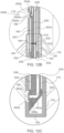
- Fig. 3C shows a view in perspective of a valve 120 in an expanded state, having its actuator assemblies 138 connected to actuation members 172 (hidden from view within the support sleeves 180) of the delivery apparatus 102.
- the leaflets 132 and skirt 136 are omitted from Fig. 3C to expose the actuator assemblies 138 attached to the frame 126.
- the actuator assembly 138 is shown in Fig. 4A in a radially compressed state of the frame valve 120, wherein the outflow and inflow apices 129 and 131, respectively, are relatively distanced apart from each other along the axial direction, and the inner member proximal end 156 is positioned distal to the outer member proximal end 142.
- the distal portion 174 of the actuation member 172 is threadedly engaged with the proximal threaded bore 160 at the proximal end 156 of the inner member 154.
- the distal portion 174 of the actuation member 172 includes external threads, configured to engage with internal threads of the proximal bore 160 of the inner member 154.
- an inner member may include a proximal extension provided with external threads, configured to be received in and engage with internal threads of a distal bore formed within the actuation member (embodiments not shown).
- the support sleeve 180 surrounds the actuation member 172 and may be connected to the handle 110.
- the support sleeve 180 and the outer member 140 are sized such that the distal lip 182 of the support sleeve 180 can abut or engage the outer member proximal end 142, such that the outer member 140 is prevented from moving proximally beyond the support sleeve 180.
- the support sleeve 180 can be held firmly against the outer member 140.
- the actuation member 172 can then be pulled in a proximally oriented direction 14, as shown in Fig. 4B . Because the support sleeve 180 is being held against the outer member 140, which is connected to an outflow apex 129, the outflow end 123 of the frame 126 is prevented from moving relative to the support sleeve 180. As such, movement of the actuation member 172 in a proximally oriented direction 14 can cause movement of the inner member 154 in the same direction, thereby causing the frame 126 to foreshorten axially and expand radially.
- the inner member coupling extension 164 extends through openings in two struts 128 interconnected at an inflow apex 131, while the outer member coupling extension 148 extends through openings in two struts 128 interconnected at an outflow apex 129.
- the inner member coupling extension 164 moves along with the inner member 154, thereby causing the portion to which the inner member coupling extension 164 is attached to move axially as well, which in turn causes the frame 126 to foreshorten axially and expand radially.
- the struts 128 to which the inner member coupling extension 164 is connected are free to pivot relative to the coupling extension 164 and to one another as the frame is expanded or compressed. In this manner, the inner member coupling extension 164 serves as a fastener that forms a pivotable connection between those struts 128.
- struts 128 to which the outer member coupling extension 148 is connected are also free to pivot relative to the coupling extension 148 and to one another as the frame is expanded or compressed. In this manner, the outer member coupling extension 148 also serves as a fastener that forms a pivotable connection between those struts 128.
- the inner member 154 can move in one axial direction, such as the proximally oriented direction 14, but cannot move in the opposite axial direction. This ensures that while the pawl 152 is engaged with the teeth 162, the frame 126 can radially expand but cannot be radially compressed.
- the frame 126 can be expanded to a desired diameter by pulling the actuation member 172. In this manner, the actuation mechanism also serves as a locking mechanism of the prosthetic valve 120.
- the actuation member 172 may be rotated in direction 16 to unscrew the actuation member 172 from the inner member 154, as shown in Fig. 4C .
- This rotation serves to disengage between the distal threaded portion 174 of the actuation member 172 and the inner member threaded bore 160, enabling the actuation arm assemblies 171 to be pulled away, and retracted, together with the delivery apparatus 102, from the patient's body, leaving the prosthetic valve 120 implanted in the patient.
- the patient's native anatomy such as the native aortic annulus in the case of transcatheter aortic valve implantation, may exert radial forces against the prosthetic valve 120 that would strive to compress it.
- the engagement between the pawl 152 and the teeth 162 of the inner member 154 prevents such forces from compressing the frame 126, thereby ensuring that the frame 126 remains locked in the desired radially expanded state.
- the prosthetic valve 120 is radially expandable from the radially compressed state shown in Fig. 4A to the radially expanded state shown in Fig. 4B upon actuating the actuator assemblies 138, wherein such actuation includes approximating the second locations to the first locations of the valve.
- the prosthetic valve 120 is further releasable from the delivery apparatus 102 by decoupling each of the actuation arm assemblies 171 from each corresponding actuator assemblies 138 that was attached thereto.
- the inner member 154 and the outer member 140 are shown in the illustrated embodiment connected to an inflow apex 131 and an outflow apex 129, respectively, it should be understood that they can be connected to other junctions 130 of the frame 126.
- the inner member coupling extension 164 can extend through openings formed in interconnected struts at a junction 130 at the inflow end portion 124, proximal to the inflow apices 131.
- the outer member coupling extension 148 can extend through openings formed in interconnected struts at a junction 130 at the outflow end portion 122, distal to the outflow apices 129.
- the handle 110 can comprise control mechanisms which may include steerable or rotatable knobs, levers, buttons and such, which are manually controllable by an operator to produce axial and/or rotatable movement of different components of the delivery apparatus 102.
- the handle 110 may comprise one or more manual control knobs, such as a manually rotatable control knob that is effective to pull the actuation members 172 when rotated by the operator.
- Prosthetic valve 120 expansion against the surrounding tissue may pose a variety of risks associated with a mismatch between the valve's expansion diameter and the surrounding tissue.
- One complication is related to valve over-expansion, which may exert excessive radial forces on the surrounding anatomy, resulting in potential damage to the tissue or even annular rupture.
- valve under-expansion might increase the risk of aortic valve or mitral valve regurgitation. Inappropriate expansion may also result in unfavorable hemodynamic performance across the valve 120, such as increased pressure gradients or flow disturbances resulting from diameter mismatch, which may be associated with increased risk of thrombus formations.
- a clinician should be able to control the degree of frame 126 expansion according to real-time feedback received during the procedure, indicating, for example, current valve diameter and/or current forces exerted by the valve on its surroundings, or reactive forces of the surrounding tissue, resisting valve expansion.
- a delivery assembly 100 equipped with at least one optic fiber sensor attached to at least one component of the delivery assembly 100, such as to the prosthetic valve 120, to the delivery apparatus 102, or to both.
- Utilization of optic fiber sensors may be advantageous due to their light weight, miniature dimension, low power consumption, high sensitivity, environmental ruggedness and low cost.
- prosthetic valves 120 will be shown throughout Figs. 5A-15C without the leaflets 132 or the skirt 136. Moreover, partial sectional views of actuation arm assemblies 171 and/or actuator assemblies 138 will be shown in otherwise perspective views of prosthetic valves 120 in Figs. 5A-15C , to expose inner structural configurations of optic fibers attached to and/or extending through components of the arm assemblies 171 and/or actuator assembly 138.
- Figs. 5A-5C showing an embodiment of a delivery assembly 100 equipped with a mechanically expandable valve 120, having at least one optic fiber assembly 210 extending through the delivery apparatus 102 and attached at its distal portion to the frame 126.
- the optic fiber assembly 210 can extend from the handle 110, through or along at last one of the components of an actuation arm assembly 171, such as the support sleeve 180 or the actuation member 172 retained therein, toward the actuator assembly 138, having its distal portion attached to a component of the actuator assembly 138, such as the inner member 154.
- Fig. 5A shows a view in perspective of a mechanically expandable valve 120 having its actuation assemblies 138 connected to actuation members 172, wherein a fiber optic assembly 210 extends through an actuation member 172 toward the inner member 154.
- the leaflets 132 and skirt 136 are omitted from Figs. 5A-5C for purposes of clarity, and the actuator assembly 138 and the respective actuation member 172 attached thereto are shown in partially sectional view to expose the fiber optic assembly 210 extending there-through.
- Fig. 5B shows a zoomed-in view of region 5B in Fig. 5A .
- the optic fiber assembly 210 comprises two optic fiber sections, detachably optically coupled to each other.
- the optic fiber assembly 210 comprises a first optic fiber section 220, extending from the handle 110 through or along the actuation arm assembly 171, up to a first fiber distal end 222, and a second optic fiber section 230 distal to the first optic fiber section 220, connected to a component of the valve 120, such as a component of the actuator assembly 138.
- the second optic fiber section 230 is connected to the inner member 154.
- the second optic fiber section 230 extends between a second fiber proximal end 232, positioned at or distal to the valve proximal end 122, and a second fiber distal end 240.
- the second fiber distal end 240 is positioned at, or proximal to, the inflow end portion 124.
- the second fiber distal end 240 is positioned at other regions of the valve 120, including any region distal to the second fiber proximal end 232, or even a region of the valve 120 which is lateral to the second fiber proximal end 232.
- the first optic fiber section 220 can include at least one first optic core
- the second optic fiber section 230 can include at least one second core.
- the first optic fiber section 220 comprises a first optic core 224 surrounded by a first fiber cladding 226, and the second optic fiber section 230 comprises a second optic core 234 surrounded by a second fiber cladding 236.
- Each of the first and/or second optic fiber sections 220 and 230 can further include a surrounding polymeric buffer coating (not shown) around the cladding 226, 236, serving as a protective buffer from the surrounding environment.
- the outer diameter of the first optic fiber section 220 is substantially equal to the outer diameter of the second optic fiber section 230. According to some embodiments, the outer diameter of the first optic core 224 is substantially equal to the outer diameter of the second optic core 234.
- substantially equal when referring to a specific measure as used herein, means no more and no less than 10% of the measure.
- a diameter of one component is substantially equal to the diameter of a second component, if the diameter of the first component is within the boundaries of 90%-110% of the second diameter.
- the first optic fiber section 220 extends through an internal channel 176 formed within the actuation member 172, and at least a portion of the second optic fiber section 230 extends through a channel 170 formed within the inner member 154 of the actuator assembly 138.
- the channels 176 and 170 are dimensioned to accommodate the first and second optic fiber sections 220 and 230, respectively, in a relatively tight manner, so as to prevent or nearly prevent lateral movement of the fiber sections 220, 230 within the channels 176, 170, respectively.
- the difference between the inner diameter of each of channels 176, 170 and the outer diameter of each of fiber sections 220, 230 is not greater than 30% of the diameter of optic cores 224, 234, respectively.
- the difference between the inner diameter of each of channels 176, 170 and the outer diameter of each of fiber sections 220, 230 is not greater than 20% of the diameter of optic cores 224, 234, respectively.
- the difference between the inner diameter of each of channels 176, 170 and the outer diameter of each of fiber sections 220, 230 is not greater than 10% of the diameter of cores 224, 234, respectively.
- the first optic fiber section 220 is detachably optically coupled to the second optic fiber section 230 when the actuation members 172 are connected to the actuator assemblies 138.
- the first fiber distal end 222 is optically coupled to the second fiber proximal end 232 when the actuation member distal portion 174 is fully engaged with the inner member threaded bore 160.
- the term 'fully engaged' relates to a state of engagement between the actuation member distal portion 174 and the inner member threaded bore 160 wherein actuation member 172 cannot move further in a distally oriented direction relative to the inner member 154, as opposed to a 'partially engaged' state, in which the actuation member distal portion 174 may be partially rotated to translate in a proximally oriented direction relative to the inner member 154, prior to disengagement therefrom.
- the interface 244 comprises an optical connector, configured to releasably couple the first fiber distal end 222 and the second fiber proximal end 232 and allow signal communication there between.
- an optical connector 244 includes alignment features configured to align the first fiber distal end 222 and the second fiber proximal end 232.
- optical coupling between the first optic fiber section 220 and the second optic fiber section 230 is achieved by placement of the first fiber distal end 222 in contact with the second fiber proximal end 232, and optical decoupling is achieved by pulling the first fiber distal end 222 away from the second fiber proximal end 232.
- the interface 244 between the first optic fiber section 220 and the second optic fiber section 230 is not realized as a distinct physical component, but rather may be defined as the contact area between the first fiber distal end 222 and the second fiber proximal end 232.
- the optical coupling of the interface 244 is realized as a physical contact (PC) connection between the first fiber distal end 222 and the second fiber proximal end 232, wherein the first optic core 224 and the second optic core 234 are aligned with each so as to optimize performance and minimize optic light loss at the interface 244 there between.
- PC physical contact
- the optical coupling 244 is realized as a flat PC, when the first fiber distal end 222 and the second fiber proximal end 232 comprise flat, and preferably polished, end faces. According to some embodiments, the optical coupling 244 is realized as an angled PC, when the first fiber distal end 222 and the second fiber proximal end 232 comprise complementary angled end faces, for example at an angle of about 8 degrees (embodiment not shown).
- the axial stress experienced by the actuation inner member 154 can be derived from the measured axial strain.
- the stress-strain relationship may be a linear or nearly-linear relationship.
- the radial stress can then be derived from the calculated axial stress.
- a linear or nearly linear relationship exists between axial stress and radial stress for a prosthetic valve 120, wherein the linear coefficient may be derived for each prosthetic valve diameter.
- a fiber optic strain assembly 210 may be utilized to provide an indication, qualitative or quantitative evaluation, or any other feedback regarding the stress experienced by the valve 120, in real-time, in-vivo, during a valve 120 implantation procedure.
- an optic fiber strain assembly 210 may be utilized to provide real-time estimation of the valve's current expansion diameter.
- One configuration that may enable diameter estimation includes a portion of the second optic fiber section 230 attached to the frame 126, or to components affixed to the frame 126, in a circumferential direction instead of being affixed to a component of the actuator assembly 138 only in an axial direction.
- the change in shift of light wavelengths results from the change in the valve's diameter can provide an estimate and/or quantitative evaluation of the current valve diameter.
- the delivery assembly 100 comprises a plurality of optic fiber strain assemblies 210, for example three optic fiber strain assemblies 210, each of which is attached to a respective actuator member 172 and actuation assembly 138.
- a plurality of fiber optic strain sensors 210 disposed at different regions around the valve 120 can provide feedback regarding radial stresses experienced at different regions along the circumference of the valve 120.
- a delivery assembly 100 may be utilized to deliver a mechanically expandable prosthetic valve 120 toward a desired implantation site in a crimped state, having the actuation members 172 attached to the actuator assemblies 138 of the valve 120, and the first optic fiber section 220 optically coupled to the second optic fiber section 230.
- the expanded valve 120 remains in the implantation site, having the second optic fiber section 230 attached thereto in a dysfunctional state.
- the small dimensions of optical fibers usually in the range of 100-200 microns, enable the second optic fiber section 230 to remain in the valve 120 in a dysfunctional state, without interfering with the valve's functioning and without externally modifying its structure or dimensions.
- a further advantage of utilizing optical fibers is that one section thereof, attached to external powering and control components, for example - at the handle 110, can be safely decoupled within a patient's body from a second section, configured to measure a desired parameter within the patient's body, without posing a risk of exposing the patient to electrical current, as no electrical current is involved.
- Figs. 5A-5C show an exemplary configuration in which the interface 244 is located within the distal portion of the actuation member channel 176, for example in the vicinity of the actuation member distal threaded portion 174, such that at least a portion of the second fiber optic section 230 extends from the inner member channel 170 into the actuation member channel 176.
- the interface 244 can be positioned in other regions, such as, for example, the inner member channel 170, having the first fiber optic section 220 extending from the actuation member channel 176 into the inner member channel 170 (configuration not shown).
- the interface 244 is located at the level of, or distal to, the outer member proximal end 142, so that once the first fiber optic section 220 is optically decoupled and retracted from the patient's body along with the remainder of the delivery apparatus 102, the second fiber optic section 230 remains hidden within the actuator assembly 138 and does not have a proximal portion thereof freely extending out of the actuator assembly 138. Stated otherwise, it is preferable that the first fiber optic section 220 does not extend beyond the outer member proximal end 142.
- the interface 244 between the optically coupled first and second optical sensor sections 220 and 230 is exemplified above as a simple contact between their end faces, it will be clear that other interfaces may be utilized for detachable optical coupling.
- the interface may include a gap configured to transfer light between the first and second optic cores 224 and 234, with minimal interference.
- An implanted prosthetic valve 120 might form a stenotic region at the site of implantation, which is usually narrower than the native annulus.
- the narrower orifice results in a portion of the blood flow's potential energy, namely pressure, being converted into kinetic energy, namely velocity, resulting in flow acceleration and pressure drop.
- Some of the energy may be irreversibly dissipated as heat, for example due to flow turbulences.
- the remaining portion of kinetic energy, which is recovered back as potential energy is termed the 'pressure recovery'.
- Pressure recovery at the outflow region of the valve 120 may be correlated with clinical outcomes.
- it is desirable to provide means for measuring the profile of valve pressure recovery therefore providing a valuable decision supporting measure for a clinician during valve deployment.
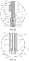
- FIGs. 6A-6D showing an embodiment of a delivery assembly 100 equipped with a mechanically expandable valve 120, having at least one optic fiber assembly 310 extending through the delivery apparatus 102 and attached at its distal portion to the frame 126, and at least one continuous optic fiber 370 extending through the delivery apparatus 102 and attached at its distal portion to at last one of the components of an actuation arm assembly 171, such as the support sleeve 180 or the actuation member 172.
- an actuation arm assembly 171 such as the support sleeve 180 or the actuation member 172.
- the optic fiber assembly 310 can extend from the handle 110, through or along at last one of the components of an actuation arm assembly 171, such as the support sleeve 180 or the actuation member 172, toward the actuator assembly 138, having its distal portion attached to a component of the actuator assembly 138, such as the inner member 154.
- an actuation arm assembly 171 such as the support sleeve 180 or the actuation member 172
- Fig. 6A shows a view in perspective of a mechanically expandable valve 120 having its actuation assemblies 138 connected to actuation members 172, wherein a fiber optic assembly 310 extends through an actuation member 172 toward the inner member 154, and wherein a continuous optic fiber 370 is attached to, and extends along, a support sleeve 180.
- Fig. 6B shows a zoomed in view of region 6B in Fig. 6A
- Fig. 6C shows a zoomed in view of region 6C in Fig. 6A .
- Fiber optic assembly 310 is generally similar in structure to fiber optic assembly 210, comprising a first optic fiber section 320 detachably optically coupled to a second optic fiber section 330.
- the first optic fiber section 320 can be identical to the first optic fiber section 220, extending from the handle 110 up to a first fiber distal end 322, comprising a first optic core 324 surrounded by a first fiber cladding 326.
- the second optic fiber section 330 is generally similar to the second optic fiber section 230, extending between a second fiber proximal end 332 positioned at, or distal to, the outflow end 123, and a second fiber distal end 340. According to alternative embodiments, the second fiber distal end 340 is positioned at, or proximal to, the outflow end 123. Unlike second optic fiber section 230 illustrated and described in accordance with Figs. 5A-5C above, the second optic fiber section 330 further comprises an axial pressure sensing head 350 at its distal end 340, enabling the fiber optic assembly 310 to function as an optic fiber pressure sensor.
- the axial sensing head 350 is a Fabry-Perot cavity based sensing head.
- Fabry-Perot sensors are attractive due to their miniature size and low costs of the sensing elements.
- the Fabry-Perot axial sensing head 350 may include a housing 352 attached to the second fiber distal end 340 having a front diaphragm 362 attached to the distal edges of housing 352.
- a front cavity 358 defined as an optical cavity, may be formed between the distal edge of a second fiber core 334 and the front diaphragm 362. Pressure may be monitored by detecting and measuring the deflection of the front diaphragm 362 to which pressure is applied.
- a Fabry-Perot sensor detects pressure applied to the diaphragm in a direction perpendicular to the surface of the diaphragm.
- the front cavity 358 and the front diaphragm 362 are coaxially aligned with the second fiber core 334.
- the optical characteristics of the light traveling along the fiber optic assembly 310 are responsive to the optical axis of the second fiber core 334. Specifically, when pressure is applied to the front diaphragm 362, the front diaphragm 362 bends into the front cavity 358, thereby changing the optical path of the light traveling through the second fiber core 334.
- the sensing head 350 may be provided without a housing 352, such that the front cavity 358 is formed at the end of the second fiber core 334, surrounded by the second fiber cladding 336 and covered by a front diaphragm 362 (embodiments not shown).
- the diaphragm can be connected directly to the distal edges of the second fiber cladding 336 in such embodiments.
- the continuous optic fiber 370 comprises a continuous optic core 374 surrounded by fiber cladding 376, and an axial sensing head 380 which is similar in structure and function to axial sensing head 350, for example having a front cavity 388 formed at the end of the optic core 374, surrounded by a housing 382 and covered by a front diaphragm 392 in a co-axial configuration.
- the channel 170 extends up to an inner member distal opening 168 at the inner member distal end 158, such that the front diaphragm 362 is at least flush with the inner member distal opening 168, or alternatively extends distally beyond the inner member distal opening 168.
- the detachable optical coupling between the first optic fiber section 320 and the second optic fiber section 330, including the function and structure interface 344, are similar to the detachable optical coupling, including interface 244, shown and described above in conjunction with Figs. 5A-5C , and are thus not described again herein.
- a delivery assembly 100 may be utilized to deliver a mechanically expandable prosthetic valve 120 toward a desired implantation site in a crimped state, having the continuous optic fiber 370 attached to the support sleeve 180, the actuation members 172 attached to the actuator assemblies 138 of the valve 120, and the first optic fiber section 320 optically coupled to the second optic fiber section 330.
- both the optic fiber assembly 310 and the continuous optic fiber 370 are shown in Figs. 6A-6D extending along the same actuation arm assembly 171, having the optic fiber assembly 310 further extending along the actuation assembly 138 attached thereto, alternative configurations are acceptable.
- the optic fiber assembly 310 may extend along one actuation arm assembly 171 and the actuation assembly 138 assembly attached thereto, while the continuous optic fiber 370 may extend along another actuation arm assembly 171 (alternative configuration not shown).
- Such a configuration may be feasible as pressure is substantially homogenous across the circumferential area at each axial position under ideal conditions.
- Embodiments of a modified optic fiber assembly 410 and a modified continuous optic fiber 470 are illustrated in Figs. 7A-7D , showing views similar to those of Figs. 6A-6D , respectively.
- Optic fiber assembly 410 and continuous optic fiber 470 may be similar to optic fiber assembly 310 and continuous optic fiber 370, respectively, with the exceptions that the optic fiber assembly 410 comprises a lateral pressure sensing head 450 instead of an axial pressure sensing head 350, and the continuous optic fiber 470 comprises a lateral pressure sensing head 480 instead of an axial pressure sensing head 380.
- Each of the lateral pressure sensing heads 450 and 480 is configured to detect pressure applied to their respective side diaphragms 462 and 492 in a direction perpendicular to the longitudinal axis of optic cores 434 and 474, respectively.
- the second optic core 434 of the second optic fiber section 430 terminates at an inclined surface 438, which is angled relative to the optical axis 442 of the second optic core 434.
- An optical side cavity 458 extends through the second fiber cladding 436 and the housing 452, overlaid by a side diaphragm 462. In other words, the side cavity 458 extends between the second fiber inclined distal core surface 438 and the side diaphragm 462.
- the lateral pressure sensing head 450 is devoid of a housing 452, such that the optical side cavity 458 extends through the fiber cladding 436, and the side diaphragm 462 is attached to the outer surface of the fiber cladding 436, or any protective layer surrounding the cladding 436 if present (embodiments not shown).
- the inclined surface 438 is preferably angled to provide a critical incidence angle for a light beam passing along the second optic core 434, in order to ensure a full reflection from the surface 438.
- the inclined surface 438 is angled at a 45° angle relative to the optical axis 442.
- other angles between the inclined surface 438 and the optical axis 442 may be applicable, as long as a critical incidence angle is provided for the light beam passing through the optic core 434.
- a light beam passing through second optic core 434 is redirected by 90° relative to the optical axis 442.
- a redirected light beam impinges on the side diaphragm 462 it reflects and is returned to the inclined surface 438 to be redirected back through the optic fiber assemble 410, for example toward an input apparatus in the handle 110.
- the side diaphragm 462 and the side cavity 458 are cross-axially aligned with the second optic core 434.
- the diaphragm 462 bends into the side cavity 458, thereby changing the path of the light beam, which changes the phase of the reflected signal.
- lateral pressure sensing head 480 at the distal end 472 of the continuous optic fiber 470 is similar to that of lateral pressure sensing head 450 described above in conjunction with Fig. 7B , including the optic core 474 terminating at an inclined distal continuous core surface 478. Accordingly, description of these elements and their operation will not necessarily be repeated with respect to the embodiments presented and discussed in conjunction with Figs. 7A-7D .
- the continuous optic fiber 470 extends through a lumen 184 of the support sleeve 180, for example attached to the outer surface of the actuation member 172, such that the lateral sensing head 470 is positioned proximal to the outflow end 123.
- the support sleeve 180 comprises a support sleeve side opening 186 extending radially outwards from the support sleeve lumen 184 at a position such that the side diaphragm 492 of the continuous optic fiber's lateral pressure sensing head 480, is co-axially aligned with the support sleeve side opening 186 along its side cavity axis 490.
- the support sleeve side opening 186 is dimensioned so as to expose the side diaphragm 492 of the continuous optic fiber's lateral pressure sensing head 480 to the surrounding environment, such as the blood flow.
- the side diaphragm 492 is flush with the outer surface of the support sleeve 180.
- the side diaphragm 492. can be positioned at a radially inward location relative to the outer surface of the support sleeve 180, or alternatively it may extend radially out of the support sleeve side opening 186.
- the circumferential orientation of the continuous optic fiber's lateral pressure sensing head 480 is preferably chosen such that in use, its side diaphragm 492 will not be blocked by surrounding tissue, such as arterial walls.
- the continuous optic fiber's lateral pressure sensing head 480 is oriented such that its side diaphragm 492 faces away from the blood vessel wall or lateral to the blood vessel wall when in use. Such configurations may help, for example, to avoid interference between the side diaphragm 492 and portions of the native anatomy that would otherwise contact the continuous optic fiber's lateral pressure sensing head 480.
- the first optic fiber section 420 extends through the actuation member internal channel 176, and at least a portion of the second optic fiber section 430 extends through a channel 170 formed within the inner member 154.
- the inner member 154 comprises an inner member side opening 166 extending radially outwards from the inner member channel 170 at a position proximal to the inner member distal end 158.
- the channel 170 of the embodiment shown in Figs. 7A-7C is not required to extend all the way up to the inner member distal end 158, but may rather terminate at a position proximal to the inner member distal end 158. While this is not a mandatory requirement in embodiments that include an inner member side opening 166, it will be clear that the inner member distal end 158 may still extend all the way to the inner member distal end 158 and terminate at an inner member distal opening 168.
- the side diaphragm 462 is co-axially aligned with the inner member side opening 166 along its side cavity axis 460.
- the inner member side opening 166 is dimensioned so as to expose the side diaphragm 462 of the optic fiber assembly lateral pressure sensing head 450 to the surrounding environment, such as the blood flow.
- the side diaphragm 462 of the optic fiber assembly lateral pressure sensing head 450 is flush with the outer surface of the inner member 154. According to alternative embodiments, the side diaphragm 462 of the optic fiber assembly lateral pressure sensing head 450 can be positioned at a radially inward location relative to the outer surface of the inner member 154, or alternatively it may extend radially out of the inner member side opening 166.
- the circumferential orientation of the optic fiber assembly lateral pressure sensing head 450 is preferably chosen such that in use, its side diaphragm 462 will not be blocked by surrounding tissue such as arterial walls, or other components of the prosthetic valve 120 such as a skirt 136.
- the optic fiber assembly lateral pressure sensing head 450 is oriented such its side diaphragm 462 faces away from the blood vessel's wall when in use, and/or away from potentially blocking components of the prosthetic valve 120.
- the optic fiber assembly lateral pressure sensing head 450 is oriented such its side diaphragm 462 is facing radially inward toward a longitudinal axis 121, or substantially tangential to the circumference of the valve 120. Such configurations may help, for example, to avoid interference between the side diaphragm 462 and portions of the native anatomy that would otherwise contact the optic fiber assembly lateral pressure sensing head 450.
- the lateral orientation of the lateral pressure sensing heads advantageously allows positioning thereof at any desired measurement point along the axial path of the valve, which would be otherwise restricted to the inner member distal end 158 if an optic fiber assembly axial pressure sensing head 350 is utilized.
- the detachable optical coupling between the first optic fiber section 420 and the second optic fiber section 430, including the function and structure interface 444, are similar to the detachable optical coupling, including interface 244, shown and described above in conjunction with Figs. 5A-5C , and are thus not described again herein.
- Fig. 7D shows the actuation member 172 disengaged from the actuator assembly 138, for example after being rotated around its longitudinal axis and pulled in a proximally oriented direction 12.
- both the continuous optic fiber 470 and the first optic fiber section 420 which are connected to the delivery apparatus 102, are pulled therewith, having the first optic fiber section 420 disconnected from the second optic fiber section 430, which remains connected to the valve 120, and more specifically, to the inner member 154.
- a delivery assembly 100 may be utilized to deliver a mechanically expandable prosthetic valve 120 toward a desired implantation site in a crimped state, having the continuous optic fiber 470 attached to the delivery apparatus and extending through a support sleeve lumen 184 such that the side diaphragm is co-axially aligned with the support sleeve side opening 186.
- the actuation members 172 are attached to the actuator assemblies 138 of the valve 120, and the first optic fiber section 420 is optically coupled to the second optic fiber section 430.
- the handle 110 can be further maneuvered to rotate the actuation members 172 around their central axes, thereby optically decoupling the first and second optic fiber sections 420 and 430. Further rotation of the actuation members 172 serves to disengage them from the actuator assemblies 138, such that the delivery apparatus 102, including the support sleeve 180 with the continuous optic fiber 470 attached thereto, and the actuation members 172 with the first optic fiber section 420 attached thereto, can be retracted from the patient's body.
- the continuous optic fiber 470 may extend through an internal channel 176 formed within the actuation member 172 instead of being attached to the external surface of the actuation member 172, such that the lateral sensing head 470 is positioned proximal to the valve's outflow end 123.
- the actuation member 172 comprises an actuation member side opening (similar to side openings 178 shown in Fig. 11B ) extending radially outward from the actuation member internal channel 176
- the support sleeve 180 comprises a corresponding support sleeve side opening (similar to side openings 186 shown in Fig.
- the actuation member side opening 178 and the support sleeve side opening 186 are dimensioned so as to expose the side diaphragm 492 of the continuous optic fiber's lateral pressure sensing head 480 to the surrounding environment, such as the blood flow.
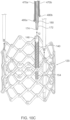
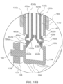
- Figs. 8A-8D showing further embodiments of a delivery assembly 100 equipped with a mechanically expandable valve 120, having at least one multi-core optic fiber assembly 510 extending through the delivery apparatus 102 and attached at its distal portion to the frame 126.
- the optic fiber assembly 510 can extend from the handle 110, through or along an actuation arm assembly 171 toward the actuator assembly 138, having its distal portion attached to a component of the actuator assembly 138, such as the inner member 154.
- Fig. 8A shows a view in perspective of a mechanically expandable valve 120 having its actuation assemblies 138 connected to actuation members 172, wherein a fiber optic assembly 510 extends through an actuation member 172 toward the inner member 154.
- Fig. 8B shows a zoomed in view of region 8B in Fig. 8A .
- Fig. 8C shows a zoomed in view of region 8C in Fig. 8A .
- any optic fiber of the current disclosure can include a plurality of internal cores, surrounded by the optic fiber cladding.
- Each optic core may include, or be attached to, a separate pressure sensing head at its distal end.
- a multi-core optic fiber can advantageously enable pressure measurements along a plurality of axially-spaced measurement points, dictated by different axial positions of the sensing heads, provided on a single optic fiber.
- the exemplary multi-core fiber optic assembly 510 shown in Figs. 8A-8C includes two first optic cores 524a and 524b surrounded by the first fiber cladding 526, and two second optic cores 534a and 534b surrounded by the second fiber cladding 536.
- the structure and function of the lateral pressure sensing head 550a at the distal end of second optic core 534a, and the lateral pressure sensing head 550b at the distal end of second optic core 534b, are similar to those of lateral pressure sensing head 450 described in conjunction with Fig. 7B above, including the second optic cores 534a and 534b terminating at inclined surfaces 538a and 538b, respectively. Accordingly, description of these elements and their operation will not necessarily be repeated with respect to the embodiments presented and discussed in conjunction with Figs. 8A-8C .
- one lateral pressure sensing head 550a may be positioned in the region of the outflow end portion 122 of the prosthetic valve 120, while another lateral pressure sensing head 550b may be positioned in the region of the inflow end portion 124, such that pressure difference across the valve 120 may be calculated.
- the first optic fiber section 520 extends through an actuation member internal channel 176, and at least a portion of the second optic fiber section 530 extends through an inner member internal channel 170.
- the inner member 154 comprises a plurality of inner member side openings 166 each extending radially outwards from the inner member channel 170, the plurality member side openings 166 being axially spaced from each other.
- the inner member 154 comprises two side openings 166a and 166b, wherein the side diaphragm 562a of the optic fiber assembly lateral pressure sensing head 550a is co-axially aligned with the inner member side opening 166a along its side cavity axis 560a, and wherein the side diaphragm 562b of the optic fiber assembly lateral pressure sensing head 550b is co-axially aligned with the inner member side opening 166b along its side cavity axis 560b.
- the housing 140 may also include at least one outer member side opening 157 extending radially outwards from the outer member lumen 146 at a position such that the side diaphragm 562a pressure sensing head 450a at the outflow end portion 122, is co-axially aligned with inner member side opening 166a and the outer member side opening 157.
- each of the plurality of inner member side openings 166 The dimensions of each of the plurality of inner member side openings 166, the relative position of each optic fiber assembly lateral pressure sensing heads 550 relative to its respective side opening 166, and the circumferential orientation of each optic fiber assembly lateral pressure sensing head 550, are similar to those illustrated and described above for inner member side opening 166 and optic fiber assembly lateral pressure sensing head 450 in conjunction with Figs. 7A-C , and are thus not described again herein.
- the outer member side opening 157 is dimensioned so as to expose the side diaphragm 562a to the surrounding environment, such as the blood flow.
- the axial position of the pressure sensing head 450a may change during valve expansion or compression.
- it is desirable that the outer member side opening 157 will be formed and dimensioned so as to allow exposure of the side diaphragm 562a to the surrounding environment during the entire working range of the prosthetic valve 120, preferably between a fully compressed state and a fully expanded state of the valve.
- the outer member side opening 157 is a longitudinal slot, having an axial length suitable to expose the side diaphragm 562a, optionally through an inner member side opening 166a, to the surrounding environment along an axial path range of the pressure sensing head 450a between compressed and expanded states of the prosthetic valve 120.
- the width of the outer member side opening 157 may be substantially equal to the width of the inner member side opening 166a, while the axial length of the outer member side opening 157 may be longer than the axial length of the inner member side opening 166a.
- the detachable optical coupling between the first optic fiber section 520 and the second optic fiber section 530 are similar to the detachable optical coupling, including interface 244, shown and described above in conjunction with Figs. 5A-5C , and are thus not described again herein except with regard to the differences between optically coupling single-core optic fiber segments and multiple-core optic fiber segments.
- a PC connection between the first optic fiber section 520 and the second optic fiber section 530 may be realized by aligning each of the first optic cores 524 with the respective second optic cores 534. For example, aligning first optic core 524a with second optic core 534a, aligning first optic core 524b with second optic core 534b, and so on.
- the number of cores and respective optic fiber assembly lateral pressure sensing heads 550 may be higher than two.
- utilization of a plurality of pressure sensing heads along the valve's flow path provides a higher resolution due to a larger number of measurement points, thereby enabling to derive more accurate pressure recovery profiles.
- Figs. 8A-8D show one embodiment of a multi-core fiber optic assembly 510 equipped with a plurality of lateral pressure sensing heads 550.
- a multi-core fiber optic assembly 510 may comprise at least one axial pressure sensing head and at least one lateral pressure sensing head 550.
- the at least one axial pressure sensing head is similar in structure and function to the axial pressure sensing head 350 described above, and is attached to or formed at the distal end of one of the second optic cores 534, such that the axial pressure sensing head is located at the second fiber distal end 540.
- the at least one lateral pressure sensing heads 550 is thereby positioned proximal to the axial pressure sensing head.
- the inner member 154 comprises both an inner member distal opening 168, and at least one side opening 166, such that the front diaphragm of the axial pressure sensing head is either flush with the inner member distal opening 168 or extending distally therefrom, and each side diaphragm 560 of a lateral pressure sensing heads 550 is co-axially aligned with a corresponding inner member side opening 166 and potentially with or along the axial length of an outer member side opening 157.
- a plurality of axially spaced pressure sensor heads are attached to the delivery apparatus 102, such that each of the pressure sensor heads is proximal to the valve's outflow portion 122.
- a plurality of axially spaced pressure sensor heads are attached to at least one actuation arm assembly 171.
- a plurality of continuous optic fibers, each equipped with at least one pressure sensing head are attached to at least one actuation arm assembly 171.
- at least one multi-core continuous optic fiber, equipped with a plurality of axially spaced pressure heads is attached to at least one actuation arm assembly 171.
- a plurality of continuous optic fibers 370 are attached to at least one component of the delivery apparatus 102, such as at least one actuation arm assembly 171.
- a plurality of continuous optic fibers 370 are attached to a support sleeve 180.
- Fig. 9A shows a view in perspective of a mechanically expandable valve 120 having its actuation assemblies 138 connected to actuation members 172, wherein two continuous optic fibers 370a and 370b are attached to, and extending along, the support sleeve 180.
- Fig. 9B shows a zoomed-in view of region 9B in Fig. 9A .
- the plurality of axial pressure sensing heads 380 are axially spaced from each other, to provide pressure measurements at different axial positions along the support sleeve 180.
- the axial pressure sensing head 380a is axially closer to the valve outflow end portion 122, that is to say that the position of the axial pressure sensing head 380a is distal to the position of axial pressure sensing head 380b.
- at least one of the plurality of pressure sensing heads 380 is positioned in a relative close proximity to the valve's outflow end 123.
- the most distal axial pressure sensing head 380a can be positioned at or in close proximity to the support member distal lip 182.
- the delivery assembly 100 does not include optic fiber assemblies attached to the valve 120. Rather, according to some embodiments, the delivery assembly 100 comprises a plurality of continuous optic fibers attached to the delivery apparatus 102, for example to at least one actuation arm assembly 171.
- Such configurations rely on an assumption that the pressure at the inflow region of the valve 120, which is not measured directly in the absence of an optic fiber assembly attached to the valve 120, can be mathematically extrapolated from the pressure readings received from the plurality of the pressure sensing heads proximal to the valve 120, in order to derive an estimated complete pressure recovery profile across the valve 120.
- Fig. 9C shows the actuation member 172 and its support sleeve 180 disengaged from the actuator assembly 138, for example after being rotated around its longitudinal axis and pulled in a proximally oriented direction 12. In this state, all of the continuous optic fibers 370 are pulled therewith, while the valve 120 remains at the implantation site without having any excessive components attached thereto.
- Figs. 9A-9C Although two continuous optic fibers 370 are shown in Figs. 9A-9C , the number of continuous optic fibers 370 may vary.
- utilization of a plurality of pressure sensing heads along the valve's flow path provides a higher resolution due to a larger number of measurement points, thereby enabling to derive more accurate pressure recovery profiles.
- Additional optional configurations may include at least one continuous optic fiber 370 extending along one support sleeve 180, and a plurality of other continuous optic fibers 370 extending along another support sleeve 180 (configurations not shown).
- FIG. 10A-10C An additional configuration of attaching continuous optic fibers to a delivery apparatus 102 is shown in Figs. 10A-10C .
- the configuration shown in Figs. 10A-10C is similar to that shown in Figs. 9A-9C , except that a plurality of continuous optic fibers 470 are equipped with axially spaced lateral pressure sensing heads 480.
- the continuous optic fibers 470 are attached to at least one actuation arm assembly 171, for example to at least one support sleeve 180.
- FIG. 10A shows a view in perspective of a mechanically expandable valve 120 having its actuation assemblies 138 connected to actuation members 172, wherein two continuous optic fibers 470a and 470b are attached to, and extending along, a support sleeve 180.
- Fig. 10B shows a zoomed in view of region 10B in Fig. 10A .
- the plurality of lateral pressure sensing heads 480 are axially spaced from each other, to provide pressure measurements at different axial positions along the support sleeve 180.
- the position of the axial pressure sensing head 480a is distal to the position of axial pressure sensing head 480b.
- the general consideration regarding axial and/or lateral positions described in connection with the plurality of axial pressure sensing heads 380 similarly apply to the plurality of lateral pressure sensing heads 480.
- Fig. 10C shows the actuation member 172 and its support sleeve 180 disengaged from the actuator assembly 138, for example after being rotated around its longitudinal axis and pulled in a proximally oriented direction 12.
- all of the continuous optic fibers 470 are pulled therewith, while the valve 120 remains at the implantation site without having any excessive components attached thereto, exhibiting the same advantage as described above for the configuration of the plurality of continuous optic fibers 370 attached to the support sleeve 180.
- a plurality of continuous optic fibers 470 equipped with axially spaced lateral pressure sensing heads 480 are attached to an actuation member 172 instead of to a support sleeve 180.
- the general considerations regarding arrangement and positioning of the continuous optic fibers 470 and the axially spaced lateral pressure sensing heads 480, when attached to an actuation member 172, are similar to those described above for the same components when attached to a support member 180.
- a plurality of continuous optic fibers 470 may extend through the support sleeve lumen 184, for example attached to the outer surface of the actuation member 172.
- the support sleeve 180 may include a plurality of support sleeve side openings 186, wherein each support sleeve side opening 186 is aligned with a respective lateral pressure sensing head 480, and is dimensioned so as to expose the corresponding side diaphragm 492 to the surrounding environment, such as the blood flow.
- a plurality of continuous optic fibers 470 may extend through an actuation member channel 176.
- the actuation member 172 may include a plurality of actuation member side openings 178
- the support sleeve 180 may include a plurality of support sleeve side openings 186, such that each support sleeve side opening 186 is aligned with both a respective actuation member side opening 178 and a lateral pressure sensing head 480.
- the support sleeve side openings 186 and the actuation member side openings 178 are dimensioned so as to expose the corresponding side diaphragms 492 to the surrounding environment, such as the blood flow.
- FIG. 11A shows a view in perspective of a mechanically expandable valve 120 having its actuation assemblies 138 connected to actuation members 172, wherein a continuous optic fiber 570 extends through an actuation member channel 176, and may be attached to an inner surface of the actuation member channel 176.
- Fig. 11B shows a zoomed in view of region 11B in Fig. 11A .
- Continuous optic fiber 570 is generally similar in structure to continuous optic fiber 470, with the exception that it comprises a plurality of continuous optic cores 574 and a plurality of lateral pressure sensing heads 580 at the end of respective continuous optic cores 574.
- the exemplary multi-core continuous optic fiber 570 shown in Figs. 11A-11B includes two continuous optic cores 574a and 574b surrounded by the fiber cladding 576.
- lateral pressure sensing head 580a at the distal end of continuous optic core 574a and the lateral pressure sensing head 580b at the distal end of continuous optic core 574b, are similar to those of lateral pressure sensing heads 480 described in conjunction with Fig. 7C above, including the continuous optic cores 574a and 574b terminating at inclined distal continuous core surfaces 578a and 578b, respectively. Accordingly, description of these elements and their operation will not necessarily be repeated with respect to the embodiments presented and discussed in conjunction with Figs. 11A-11C .
- the plurality of lateral pressure sensing heads 580 are axially spaced from each other, to provide pressure measurements at different axial positions along the continuous optic fiber 570.
- the lateral pressure sensing head 580a is axially closer to the valve's outflow end portion 122, that is to say that the position of the lateral pressure sensing heads 580a is distal to the position of lateral pressure sensing head 580b.
- the general considerations regarding axial positions described in connection with the plurality of axial pressure sensing heads 380 of separate continuous optic fibers 370 similarly apply to the plurality of lateral pressure sensing heads 580 of a single multi-core continuous optic fiber 570.
- the actuation member 172 comprises two side openings 178a and 178b
- the support sleeve 180 comprises two side openings 186a and 186b
- the side diaphragm 592a of the continuous optic fiber lateral pressure sensing head 580a is co-axially aligned with the actuation member side opening 178a and the support sleeve side opening 186a along its side cavity axis 590a
- the side diaphragm 592b of the continuous optic fiber's lateral pressure sensing head 580b is co-axially aligned with the actuation member side opening 178b and the support sleeve side opening 186b along its side cavity axis 590b (axes 590a and 590b not shown explicitly in Figs. 11A-11C to avoid clutter).
- Fig. 11C shows the actuation member 172 and its support sleeve 180 disengaged from the actuator assembly 138, for example after being rotated around its longitudinal axis and pulled in a proximally oriented direction 12.
- the multi-core continuous optic fiber 570 is pulled therewith, while the valve 120 remains at the implantation site without having any excessive components attached thereto, exhibiting the same advantage as described above for the configuration of the plurality of continuous optic fibers 370 or 470 attached to the support sleeve 180.
- Figs. 11A-11C Although two continuous cores 574 with two corresponding continuous optic fiber's lateral pressure sensing head 580 are shown in Figs. 11A-11C , the number of cores 574 and respective continuous optic fiber's lateral pressure sensing heads 580 may vary. The general considerations regarding the amount of fibers described in connection with a plurality of continuous optic fibers 370 described above and illustrated in Figs. 9A-9C , similarly apply to the number of continuous cores 574 within a single multi-core continuous optic fiber 570.
- Figs. 11A-11C show one embodiment of a multi-core continuous optic fiber 570 equipped with a plurality of lateral pressure sensing heads 580.
- a multi-core continuous optic fiber 570 may comprise at least one axial pressure sensing head and at least one lateral pressure sensing heads 580.
- the at least one axial pressure sensing head is similar in structure and function to the axial pressure sensing head 380 described above, and is attached to, or formed at, the distal end of one of the continuous optic cores 574, such that the axial pressure sensing head is located at the fiber distal end 572.
- the at least one lateral pressure sensing heads 580 is thereby positioned proximal to the axial pressure sensing head.
- Such embodiments are mainly applicable for configurations having the multi-core continuous optic fiber 570 attached to the outer surface of a support sleeve 180, wherein the axial pressure sensing head may be positioned in close vicinity to the valve's proximal end 122.
- a multi-core continuous optic fiber 570 equipped with a plurality of lateral pressure sensing head 580 may extend through the support sleeve lumen 184, for example, by being attached to an outer surface of the actuation member 172, wherein the support sleeve 180 comprises a plurality of support sleeve side openings 186 positioned in alignment with the plurality of lateral pressure sensing head 580.
- the exemplary multi-core fiber optic assembly 610 shown in Figs. 12A-12D includes two first optic cores 624a and 624b surrounded by the first fiber cladding 626, and a single optic core 634 surrounded by the second fiber cladding 636.
- the structure and function of the lateral pressure sensing head 650a at the distal end of second optic core 634, and the lateral pressure sensing head 650b at the distal end of first optic core 624b, are similar to those of lateral pressure sensing head 450 illustrated and described in conjunction with Fig. 7B above, including the second optic core 634 terminating at a second fiber core inclined distal surface 638, and the first optic core 624b terminating at a first fiber core's inclined distal surface 628, respectively. Accordingly, description of these elements and their operation will not necessarily be repeated with respect to the embodiments presented and discussed in conjunction with Figs. 12A-12D .
- the lateral pressure sensing heads 750 are oriented radially outward, such that their lateral extensions 756, having the side diaphragms 762 attached thereto, are extending beyond the perimeter of the valve frame 126, thereby allowing the side diaphragms 762 to contact the blood vessel wall during valve expansion.
- This arrangement allows the lateral pressure sensing head 750 to function as a lateral contact-force sensing head, configured to detect and measure a contact force applied by the prosthetic valve 120 when it is in contact with, and is pressed against, the surrounding tissue, such as a native annulus.
- Such a contact-force sensing head 750 may provide information and feedback to the operator regarding the resistive force being applied to the prosthetic valve 120. For example, when a detected contact force exceeds a predetermined pressure threshold (e.g., corresponding to a pressure that may cause tissue damage or potentially even annular rupture during) during valve expansion, the delivery system may produce an alert. For example, the handle 110 may produce a detectable, visual or auditory, alert.
- a predetermined pressure threshold e.g., corresponding to a pressure that may cause tissue damage or potentially even annular rupture during
- a lateral contact-force sensing head 750 attached to a prosthetic valve 120 provides valuable feedback to the clinician with respect to the force being applied to the surrounding tissue, which may enable to prevent, or at least reduce, potential trauma to a tissue (e.g., the annulus).
- a plurality of optic fiber assemblies may extend through the same actuation arm assembly 171 and the same actuator assembly 138.
- a plurality of optic fiber assemblies may extend through a single actuation arm channel 176 and a single inner member channel 170.
- one side diaphragm 462a of an optic fiber assembly lateral pressure sensing head 450a is co-axially aligned with the side opening 166a that extends radially outward from the longitudinal axis 121
- another side diaphragm 462b of another optic fiber assembly lateral pressure sensing head 450b is co-axially aligned with the opposite side opening 166b that extends radially inward toward the longitudinal axis 121.
- This configuration enables simultaneous pressure measurements within the valve 120, and outside the valve 120, which can be useful, for example, for detecting hemodynamic disorders both in the Left Ventricle Outflow Tract (LVOT) as well as the internal pressure within the valve itself, assuming that the inflow portion 124 to which both lateral pressure sensing head 450 are attached, extends into the left ventricle.
- two second optic fiber section 430a and 430b are attached to, and optionally extend through, the same actuator assembly 138, such that their respective lateral pressure sensing heads 450a and 450b are oriented at diametrically opposing radial directions.
- An outwardly oriented pressure sensing head such as the pressure sensing head 450b of Figs. 14A-B , may be further useful for detection of paravalvular leakage during prosthetic valve 120 implantation.
- optic fiber assemblies 410a and 410b are shown in the embodiment of Figs. 14A-14B extending through a single actuation member channel 176 and a single inner member channel 170, other embodiments may include at least two separate actuation member channels 176 extending through the same actuation member 172, and at least two separate actuation member channels 176 extending through the same inner member 154, wherein each separate channel is configured to accommodate a single optic fiber section, thereby facilitating easier alignment of their respective optic cores at interface 444.
- Fig. 14C shows the actuation member 172 disengaged from the actuator assembly 138, for example after being rotated around its longitudinal axis and pulled in a proximally oriented direction 12.
- the at least two first optic fiber sections 420a and 420b which are connected to the delivery apparatus 102, are pulled therewith after being disconnected from the respective at least two second optic fiber sections 430a and 430b, which remain connected to the valve 120, and more specifically, to the inner member 154.
- a multi-core optic fiber assembly equipped with at least two lateral pressure sensing heads may extend through an actuation arm assembly 171 and an actuator assembly 138, for example through an actuation arm channel 176 and an inner member channel 170, having both lateral pressure sensing heads attached to the actuator assembly 138 and oriented at diametrically opposing radial directions.
- FIGs. 15A-15C showing embodiments of a delivery assembly 100 equipped with a mechanically expandable valve 120, having at least one multi-core optic fiber assembly 810 extending through the delivery apparatus 102, and attached at its distal portion, to the frame 126.
- Fig. 15A shows a view in perspective of a mechanically expandable valve 120 having its actuation assemblies 138 connected to actuation members 172, wherein a multi-core fiber optic assembly 810 extends through an actuation member 172 toward the inner member 154.
- Fig. 15B shows a zoomed-in view of region 15B in Fig. 15A .
- Multi-core fiber optic assembly 810 is generally similar in structure to multi-core fiber optic assembly 510, comprising at least two optic cores extending through the first and second optic fiber sections 820 and 830, with the exception that at least two lateral pressure sensing heads 850a and 850b at the distal ends of corresponding second optic cores 834a and 834b, respectively, are oriented at diametrically opposing radial directions.
- the exemplary multi-core fiber optic assembly 810 shown in Figs. 15A-15C includes two first optic cores 824a and 824b surrounded by the first fiber cladding 826, and two second optic cores 834a and 834b surrounded by the second fiber cladding 836.
- the structure and function of the lateral pressure sensing head 850a at the distal end of second optic core 834a, and the lateral pressure sensing head 850b at the distal end of second optic core 834b, are similar to those of lateral pressure sensing head 850 described in conjunction with Fig. 7B above, including the second optic cores 834a and 834b terminating at second optic core inclined distal surfaces 838a and 838b, respectively. Accordingly, description of these elements and their operation will not necessarily be repeated with respect to the embodiments presented and discussed in conjunction with Figs. 15A-15C .
- the first optic fiber section 820 extends through an actuation member internal channel 176, and at least a portion of the second optic fiber section 830 extends through an inner member internal channel 170.
- One side diaphragm 862a of an optic fiber assembly lateral pressure sensing head 850a is co-axially aligned with the side opening 166a that extends radially outwards from the longitudinal axis 121
- another side diaphragm 862b of another optic fiber assembly lateral pressure sensing head 850b is co-axially aligned with the opposite side opening 166b that extends radially inwards from the longitudinal axis 121.
- Figs. 15A-15B While both of the side openings 166 and the corresponding pressure sensing heads 850 aligned therewith are illustrated in Figs. 15A-15B in close proximity to the inner member distal end 158, it will be understood that the side openings 166 can be formed at any other position along the length of the inner member 154, having the corresponding pressure sensing heads 850 aligned therewith.
- each of the lateral pressure sensing heads 850a and 850b, along with its respective side opening 166a and 166b, can be located at a different axial position along the length of the inner member 154, such that the pressure sensing heads 850a and 850b of a single a single second optic fiber section 830 can be both axially spaced from each other, and oriented at diametrically opposing radial directions.
- the detachable optical coupling between the first optic fiber section 820 and the second optic fiber section 830, including the function and structure interface 844, are similar to the detachable optical coupling, including interface 544, shown and described above in conjunction with Figs. 8A-8C , and are thus not described again herein.
- a delivery assembly 100 comprises at least one multi-core optic fiber 1100 attached to either a component of the delivery apparatus 102 and/or to a component of the prosthetic valve 120, having axially spaced pressure sensing heads 1200.
- the multi-core optic fiber 1100 may take the form of any of the above described multi-core optic fibers, such as multi-core optic fiber assemblies 510, 610, 810, or multi-core continuous optic fiber 570.
- a pressure sensing head 1200 may take the form of any of the above described pressure sensing heads, such as axial pressure sensing heads 350, 380 or lateral pressure sensing heads 450, 480, 650, 750, 850.
- a delivery assembly 100 comprises at least two optic fibers 1000, each equipped with at least one pressure sensing head 1200, wherein at least two pressure sensing heads are axially spaced from each other, and wherein each of the optic fibers is attached to either a component of the delivery apparatus 102 and/or to a component of the prosthetic valve 120.
- the optic fiber 1000 may take the form of any of the above described optic fibers having at least one optic core terminating at a pressure sensing head 1200, such as optic fiber assemblies 310, 410, 710, continuous optic fibers 370, 470, and/or multi-core optic fiber 1100.
- An arrangement of at least one optic fiber assembly 1010 attached to an inner member 154, extending for example through an inner member channel 170, may be similar to the attachment and operation of optic fiber assembly 310 as presented and discussed in conjunction with Figs. 6A-6D , may be similar to the attachment and operation of optic fiber assembly 410 as presented and discussed in conjunction with Figs. 7A-7D , may be similar to the attachment and operation of multi-core optic fiber assembly 510 as presented and discussed in conjunction with Figs. 8A-8C , may be similar to the attachment and operation of multi-core optic fiber assembly 610 as presented and discussed in conjunction with Figs. 12A-12D , may be similar to the attachment and operation of optic fiber assembly 710 as presented and discussed in conjunction with Figs.
- an optic fiber assembly 1010 may be attached to other regions of the actuator assembly 138, such as, but not limited to, an outer surface of the inner member 150, an inner surface of the outer member lumen 146, and/or an outer surface of the outer member 140.
- an optic fiber assembly 1010, and more specifically, a second optic fiber of an optic fiber assembly 1010 may be alternatively or additionally attached to other portions of the prosthetic valve 120, such as the frame 126, including apices 129, 131 and/or other junctions 130 thereof.
- An arrangement of at least one continuous optic fiber 1070 attached to the actuation member 172 and/or the support sleeve 180 may be similar to the attachment and operation of continuous optic fiber 370 as presented and discussed in conjunction with Figs. 6A-6D , may be similar to the attachment and operation of continuous optic fiber 470 as presented and discussed in conjunction with Figs. 7A-7D , may be similar to the attachment and operation of a plurality of continuous optic fibers 370 as presented and discussed in conjunction with Figs. 9A-9C , may be similar to the attachment and operation of a plurality of continuous optic fibers 470 as presented and discussed in conjunction with Figs. 10A-10C , or may be similar to the attachment and operation of multi-core continuous optic fiber 570 as presented and discussed in conjunction with Figs. 11A-11C .
- optic fibers 1000 attached to or embedded within one actuator assembly 138 and/or one actuation arm assembly 171
- optic fibers 1000 can be attached to or embedded within a plurality, and potentially all of the actuator assemblies 138 and/or actuation arm assemblies 171 of a delivery assembly 100.
- One specific arrangement may include a plurality of optic fiber assemblies 310 equipped with respective axial pressure sensing heads 350, attached to the prosthetic valve 120 and positioned such that the respective axial pressure sensing heads 350 are circumferentially distanced from each other around the valve 120.
- the axial pressure sensing heads 350 are positioned at the outflow end portion 122.
- the respective plurality of the diaphragms 362 of the axial pressure sensing heads 350 are flush with or distal to the respective inner member distal openings 168.
- Such an arrangement is particularly useful if a prosthetic valves 168 is mounted against the aortic annulus, such that its distal end 124 protrudes into the left ventricle, or more specifically, into the LVOT (not shown).
- Incorporating at least two axial pressure sensing heads 350 configured to provide reading from two circumferentially distanced LVOT regions may provide simultaneous measurement of flow at these regions, and comparison between such measurements for detection of abnormal flow patterns and hemodynamic disturbances, which may depend, for example, on the orientation and depth of the valve 120 within the LVOT.
- real-time detection of flow disturbances in the LVOT can be followed by corrective actions, such as valve repositioning.
- time-resolved pressure measurement can be correlated to flow using known empirical relationships established in clinical literature.
- flow patterns, such as in the region of the LVOT may be derived from pressure measurements acquired by pressure sensing heads 1200.
- the continuous optic fibers 370, 470 can be coupled to the valve 120 in a releasable manner, such as via frangible attachments, such that upon application of a pulling force thereto, exceeding a certain threshold, the continuous optic fibers 370, 470 can be forcibly detached (e.g., by tearing temporary sutures, breaking relatively weak gluing bonds, and the like), enabling such assemblies to be retracted from the patient's body, along with the remainder of the delivery apparatus 102, at the end of the implantation procedure.
- optic fibers according to any of the embodiments of the current disclosure are operatively coupled to a control unit (not shown).
- the control unit is configured to receive signals, such as optic signals, from at least one optic fiber assembly 210, representative of the axial strain of a component of the prosthetic valve 120.
- the control unit can be configured to continuously calculate the diameter and the radial force of the prosthetic valve 120 as it expands, based on measurement inputs provided by at least one optic fiber assembly 210.
- control unit is configured to receive signals from at least two pressure sensing heads 1200 oriented at diametrically opposite directions relative to the longitudinal axis 121, representative of the pressure in the vicinity of the membranes of each of the corresponding pressure sensing heads 1200.
- the control unit can be configured to continuously calculate the pressure difference between the outer and inner prosthetic valve regions, based on measurement signals provided by the at least two diametrically opposing pressure sensing heads 1200.
- the digital display 116 may similarly display other icons, textual messages and/or graphical symbols. Additionally or alternatively, led lights 118, lamps or other visual elements, can be configured to provide the user with a visual indication regarding the above mentioned parameters. According to some embodiments, the control unit is configured to display the above mentioned parameters on the digital display 116 in real-time as the prosthetic valve 120 is expanded and/or compressed during an implantation procedure.
Landscapes
- Health & Medical Sciences (AREA)
- Cardiology (AREA)
- Engineering & Computer Science (AREA)
- Biomedical Technology (AREA)
- Life Sciences & Earth Sciences (AREA)
- Transplantation (AREA)
- Heart & Thoracic Surgery (AREA)
- Vascular Medicine (AREA)
- Oral & Maxillofacial Surgery (AREA)
- Animal Behavior & Ethology (AREA)
- General Health & Medical Sciences (AREA)
- Public Health (AREA)
- Veterinary Medicine (AREA)
- Mechanical Engineering (AREA)
- Prostheses (AREA)
- Measuring And Recording Apparatus For Diagnosis (AREA)
- Length Measuring Devices By Optical Means (AREA)
Claims (15)
- Zuführanordnung (100), umfassend:
eine prothetische Herzklappe (120), die zwischen einem radial komprimierten Zustand und einem radial expandierten Zustand radial expandierbar und komprimierbar ist, wobei die prothetische Herzklappe (120) einen Abströmendabschnitt (122), einen Zuströmendabschnitt (124) und zumindest eine Aktuatoranordnung (138) umfasst, wobei jede Aktuatoranordnung (138) umfasst:ein Außenelement (140), das zwischen einem proximalen Ende (142) des Außenelements und einem distalen Ende (144) des Außenelements definiert ist, wobei das Außenelement an einer ersten Stelle der Klappe befestigt ist; undein Innenelement (160), das an einer zweiten Stelle der Klappe, die von der ersten Stelle axial beabstandet ist, befestigt ist;eine Zuführvorrichtung (102), die einen Griff (110) und zumindest eine Betätigungsarmanordnung (171), die sich von dem Griff (110) aus erstreckt, umfasst, wobei die zumindest eine Betätigungsarmanordnung (171) umfasst:ein Betätigungselement (172), das lösbar mit dem Innenelement (160) gekoppelt ist; undeinen Stützhülse (180), die das Betätigungselement (172) umgibt;dadurch gekennzeichnet, dass diese weiter umfasst:
zumindest eine optische Faseranordnung (210), umfassend:eine erste optische Fasersektion (220), die mit der Zuführvorrichtung (102) verbunden ist, wobei die erste optische Fasersektion (220) zumindest einen ersten optischen Kern (224) umfasst;eine zweite optische Fasersektion (230), die mit der prothetischen Herzklappe (120) verbunden ist, wobei die zweite optische Fasersektion (230) zumindest einen zweiten optischen Kern (234) umfasst; undein Zwischenstück (244) zwischen der ersten optischen Fasersektion (220) und der zweiten optischen Fasersektion (230), wobei das Zwischenstück (244) dazu konfiguriert ist, eine ablösbare optische Kopplung zwischen der ersten optischen Fasersektion (220) und der zweiten optischen Fasersektion (230) bereitzustellen;wobei die prothetische Herzklappe (120) durch Betätigen der zumindest einen Aktuatoranordnung (138), um die zweite Stelle der ersten Stelle anzunähern, von einem radial komprimierten Zustand in einen radial expandierten Zustand expandierbar ist;wobei die prothetische Herzklappe (120) durch Abkoppeln von jeder der zumindest einen Aktuatorarmanordnung von jeder entsprechenden Aktuatoranordnung (138) von der Zuführvorrichtung (102) lösbar ist; undwobei die zweite optische Fasersektion (230) dazu konfiguriert ist, beim Lösen der prothetischen Herzklappe (120) von der Zuführvorrichtung (102) von der ersten optischen Fasersektion (220) entkoppelt zu werden. - Zuführanordnung (100) nach Anspruch 1, wobei die zumindest eine zweite optische Fasersektion (230) eine Vielzahl von axial beabstandeten Faser-Bragg-Gittern umfasst, die entlang zumindest eines Abschnitts ihres zweiten optischen Kerns (234) angeordnet sind.
- Zuführanordnung (100) nach Anspruch 1, wobei die zweite optische Fasersektion (230) zumindest einen Drucksensorkopf (350) umfasst.
- Zuführanordnung (100) nach Anspruch 3, wobei der zumindest eine Drucksensorkopf (350) ein Axialdrucksensorkopf (350) ist, umfassend: eine Frontmembran (362) und eine Frontkavität (358) zwischen dem zumindest einen zweiten optischen Kern (234) und der Frontmembran (362), wobei sowohl die Frontmembran (362) als auch die Frontkavität (358) koaxial mit dem zumindest einen zweiten optischen Kern (234) angeordnet sind.
- Zuführanordnung (100) nach Anspruch 3, wobei der zumindest eine zweite optische Kern (234) eine geneigte distale Kernoberfläche (438) umfasst, wobei der zumindest eine Drucksensorkopf (350) ein Lateraldrucksensorkopf (450) ist, umfassend: eine Seitenmembran (462) und eine Seitenkavität (458) zwischen der geneigten, distalen Kernoberfläche (438) und der Seitenmembran (462), und wobei sowohl die Seitenmembran (462) als auch die Seitenkavität (458), axial quer zum zumindest einen, zweiten optischen Kern (234) ausgerichtet sind.
- Zuführanordnung (100) nach einem der Ansprüche 1 bis 5, wobei das Betätigungselement (172) einen Betätigungselementkanal (176) umfasst, und wobei sich zumindest ein Abschnitt der zumindest einen ersten optischen Fasersektion (220) durch den Betätigungselementkanal (176) erstreckt.
- Zuführanordnung (100) nach einem der Ansprüche 1 bis 6, wobei das Innenelement (160) einen Innenelementkanal (170) umfasst, und wobei sich zumindest ein Abschnitt der zumindest einen zweiten optischen Fasersektion (230) durch den Innenelementkanal (170) erstreckt.
- Zuführanordnung (100) nach einem der Ansprüche 1 bis 7, wobei das Zwischenstück (244) eine physikalische Kontaktverbindung zwischen der ersten optischen Fasersektion (220) und der zweiten optischen Fasersektion (230) umfasst.
- Zuführanordnung (100) nach einem der Ansprüche 1 bis 8, wobei das Zwischenstück (244) auf der Höhe oder distal des proximalen Endes (142) des Außenelements angeordnet ist.
- Zuführanordnung (100) nach einem der Ansprüche 1 bis 9, wobei die erste optische Fasersektion (220) mit dem Griff (110) verbunden ist.
- Zuführanordnung (100), umfassend:
eine prothetische Herzklappe (120), die zwischen einem radial komprimierten Zustand und einem radial expandierten Zustand radial expandierbar und komprimierbar ist, wobei die prothetische Herzklappe (120) einen Abströmendabschnitt (122), einen Zuströmendabschnitt (124) und zumindest eine Aktuatoranordnung (138) umfasst, wobei jede Aktuatoranordnung (138) umfasst:ein Außenelement (140), das an einer ersten Stelle der Klappe befestigt ist; undein Innenelement (160), das an einer zweiten Stelle der Klappe befestigt ist, die von der ersten Stelle axial beabstandet ist;eine Zuführvorrichtung (102), die einen Griff (110) und zumindest eine Betätigungsarmanordnung (171), die sich von dem Griff (110) aus erstreckt, umfasst, wobei die zumindest eine Betätigungsarmanordnung (171) umfasst:ein Betätigungselement (172), das lösbar mit dem Innenelement (160) gekoppelt ist; undeine Stützhülse (180), die das Betätigungselement (172) umgibt;dadurch gekennzeichnet, dass diese weiter umfasst:
zumindest eine kontinuierliche optische Faser (370), die an der Zuführvorrichtung (102) befestigt ist, wobei die zumindest eine kontinuierliche optische Faser (370) umfasst:zumindest einen kontinuierlichen optischen Kern (374); undzumindest einen Drucksensorkopf (350), wobei der zumindest eine Drucksensorkopf (350) eine Membran und eine optische Kavität (358) zwischen dem zumindest einen kontinuierlichen optischen Kern (374) und der Membran umfasst;wobei die prothetische Herzklappe (120) durch Betätigen der zumindest einen Aktuatoranordnung (138), um die zweite Stelle der ersten Stelle anzunähern, von einem radial komprimierten Zustand in einen radial expandierten Zustand expandierbar ist;wobei die prothetische Herzklappe (120) durch Entkoppeln jeder der zumindest einen Betätigungsarmanordnung (171) von der jeweils entsprechenden Betätigungsanordnung (138) von der Zuführvorrichtung (102) lösbar ist; undwobei jeder Drucksensorkopf (350) proximal des Abströmendabschnitts (122) der prothetischen Herzklappe (120) positioniert ist. - Zuführanordnung (100) nach Anspruch 11, wobei die zumindest eine kontinuierliche optische Faser (370) an der Betätigungsarmanordnung (171) angebracht ist.
- Zuführanordnung (100) nach Anspruch 11, wobei die zumindest eine kontinuierliche optische Faser (370) an einer äußeren Oberfläche der Stützhülse (180) angebracht ist.
- Zuführanordnung (100) nach Anspruch 11, wobei die zumindest eine kontinuierliche optische Faser (370) eine Vielzahl von kontinuierlichen optischen Fasern (370) umfasst, die an der Zuführvorrichtung (102) angebracht sind, so dass die entsprechende Vielzahl der Drucksensorköpfe (350) axial voneinander beabstandet sind.
- Zuführanordnung (100) nach einem der Ansprüche 11 bis 14, wobei die zumindest eine kontinuierliche optische Faser (370) eine vielkernige kontinuierliche optische Faser (370) ist, die eine Vielzahl von optischen Kernen (374) und eine Vielzahl von axial beabstandeten Drucksensorköpfen (350) umfasst.
Priority Applications (1)
| Application Number | Priority Date | Filing Date | Title |
|---|---|---|---|
| EP23218146.1A EP4324428A3 (de) | 2019-10-31 | 2020-10-27 | Ventile und abgabevorrichtungen mit glasfasersensoren |
Applications Claiming Priority (2)
| Application Number | Priority Date | Filing Date | Title |
|---|---|---|---|
| US201962928599P | 2019-10-31 | 2019-10-31 | |
| PCT/US2020/057515 WO2021086844A1 (en) | 2019-10-31 | 2020-10-27 | Valves and delivery apparatuses equipped with optic fiber sensors |
Related Child Applications (1)
| Application Number | Title | Priority Date | Filing Date |
|---|---|---|---|
| EP23218146.1A Division EP4324428A3 (de) | 2019-10-31 | 2020-10-27 | Ventile und abgabevorrichtungen mit glasfasersensoren |
Publications (2)
| Publication Number | Publication Date |
|---|---|
| EP4051189A1 EP4051189A1 (de) | 2022-09-07 |
| EP4051189B1 true EP4051189B1 (de) | 2023-12-20 |
Family
ID=73498305
Family Applications (2)
| Application Number | Title | Priority Date | Filing Date |
|---|---|---|---|
| EP20811179.9A Active EP4051189B1 (de) | 2019-10-31 | 2020-10-27 | Mit faseroptischen sensoren ausgestattete ventile und ausgabevorrichtung |
| EP23218146.1A Pending EP4324428A3 (de) | 2019-10-31 | 2020-10-27 | Ventile und abgabevorrichtungen mit glasfasersensoren |
Family Applications After (1)
| Application Number | Title | Priority Date | Filing Date |
|---|---|---|---|
| EP23218146.1A Pending EP4324428A3 (de) | 2019-10-31 | 2020-10-27 | Ventile und abgabevorrichtungen mit glasfasersensoren |
Country Status (6)
| Country | Link |
|---|---|
| US (1) | US20220257379A1 (de) |
| EP (2) | EP4051189B1 (de) |
| JP (1) | JP7549613B2 (de) |
| CN (1) | CN114615955A (de) |
| CA (1) | CA3143730A1 (de) |
| WO (1) | WO2021086844A1 (de) |
Families Citing this family (3)
| Publication number | Priority date | Publication date | Assignee | Title |
|---|---|---|---|---|
| AU2021224599A1 (en) * | 2020-02-18 | 2021-12-23 | Edwards Lifesciences Corporation | Apparatus for monitoring valve expansion |
| US12426890B2 (en) | 2021-03-19 | 2025-09-30 | Evalve, Inc. | Systems for tissue grasping and assessment |
| WO2024158595A1 (en) * | 2023-01-24 | 2024-08-02 | Medtronic, Inc. | Heart valve implant apparatus |
Family Cites Families (19)
| Publication number | Priority date | Publication date | Assignee | Title |
|---|---|---|---|---|
| US5871489A (en) | 1996-01-24 | 1999-02-16 | S.M.T. (Medical Technologies) Ltd | Surgical implement particularly useful for implanting prosthetic heart valves, valve holder particularly useful therewith and surgical method including such implement |
| US6893460B2 (en) | 2001-10-11 | 2005-05-17 | Percutaneous Valve Technologies Inc. | Implantable prosthetic valve |
| JP5386363B2 (ja) | 2007-05-17 | 2014-01-15 | Dic株式会社 | ネマチック液晶組成物及びバイステイブルネマチック液晶表示素子 |
| SI3476368T2 (sl) | 2008-06-06 | 2025-09-30 | Edwards Lifesciences Corporation | Transkatetrska srčna zaklopka z nizkim profilom |
| EP2340075B1 (de) * | 2008-10-10 | 2013-03-06 | Sadra Medical, Inc. | Medizinische vorrichtungen und abgabesysteme zur abgabe von medizinischen vorrichtungen |
| US8353953B2 (en) | 2009-05-13 | 2013-01-15 | Sorin Biomedica Cardio, S.R.L. | Device for the in situ delivery of heart valves |
| US20120041533A1 (en) * | 2010-08-10 | 2012-02-16 | Boston Scientific Scimed, Inc. | Stent delivery device |
| US9827093B2 (en) | 2011-10-21 | 2017-11-28 | Edwards Lifesciences Cardiaq Llc | Actively controllable stent, stent graft, heart valve and method of controlling same |
| US20140243688A1 (en) | 2011-10-28 | 2014-08-28 | Three Rivers Cardiovascular Systems Inc. | Fluid temperature and flow sensor apparatus and system for cardiovascular and other medical applications |
| US11406498B2 (en) * | 2012-12-20 | 2022-08-09 | Philips Image Guided Therapy Corporation | Implant delivery system and implants |
| JP6511781B2 (ja) | 2014-11-13 | 2019-05-15 | 日本ゼオン株式会社 | 医療用スタイレット |
| EP3247311B1 (de) | 2015-01-22 | 2020-03-18 | Koninklijke Philips N.V. | Endograftvisualisierung mit vorintegrierten anbaugeräten zur optischen formmessung |
| US11185413B2 (en) * | 2016-07-13 | 2021-11-30 | Medfree, Inc. | Tissue grasping devices and related methods |
| US10603165B2 (en) | 2016-12-06 | 2020-03-31 | Edwards Lifesciences Corporation | Mechanically expanding heart valve and delivery apparatus therefor |
| US10869759B2 (en) | 2017-06-05 | 2020-12-22 | Edwards Lifesciences Corporation | Mechanically expandable heart valve |
| US10806573B2 (en) | 2017-08-22 | 2020-10-20 | Edwards Lifesciences Corporation | Gear drive mechanism for heart valve delivery apparatus |
| EP4512371A3 (de) * | 2018-10-30 | 2025-05-14 | Edwards Lifesciences Corporation | Ventildurchmesser- und -kraftüberwachung einer herzklappenprothese |
| CN114025710A (zh) * | 2019-12-06 | 2022-02-08 | 爱德华兹生命科学公司 | 用于在程序期间测量实时瓣膜直径的挠曲传感器 |
| CN216455277U (zh) * | 2020-10-13 | 2022-05-10 | 巴德阿克塞斯系统股份有限公司 | 用于将医疗器械插入患者体内的医疗器械系统 |
-
2020
- 2020-10-27 EP EP20811179.9A patent/EP4051189B1/de active Active
- 2020-10-27 CN CN202080076267.2A patent/CN114615955A/zh active Pending
- 2020-10-27 EP EP23218146.1A patent/EP4324428A3/de active Pending
- 2020-10-27 CA CA3143730A patent/CA3143730A1/en active Pending
- 2020-10-27 WO PCT/US2020/057515 patent/WO2021086844A1/en not_active Ceased
- 2020-10-27 JP JP2021574310A patent/JP7549613B2/ja active Active
-
2022
- 2022-04-29 US US17/732,707 patent/US20220257379A1/en active Pending
Also Published As
| Publication number | Publication date |
|---|---|
| JP7549613B2 (ja) | 2024-09-11 |
| JP2023500423A (ja) | 2023-01-06 |
| US20220257379A1 (en) | 2022-08-18 |
| EP4324428A3 (de) | 2024-04-17 |
| WO2021086844A1 (en) | 2021-05-06 |
| EP4324428A2 (de) | 2024-02-21 |
| CN114615955A (zh) | 2022-06-10 |
| CA3143730A1 (en) | 2021-05-06 |
| EP4051189A1 (de) | 2022-09-07 |
Similar Documents
| Publication | Publication Date | Title |
|---|---|---|
| US20220257379A1 (en) | Valves and delivery apparatuses equipped with optic fiber sensors | |
| US12539212B2 (en) | Flex sensors for measuring real-time valve diameter during procedure | |
| JP7648547B2 (ja) | 心臓弁交換に関連付けられる生理学的パラメータのリアルタイム測定 | |
| JP7314246B2 (ja) | 経中隔送達システム | |
| US10537287B2 (en) | Sensors for prosthetic heart devices | |
| EP3182932B1 (de) | Sensoren für künstliche herzvorrichtungen | |
| US20220331132A1 (en) | Devices and methods for prosthetic valve diameter estimation | |
| US20250000649A1 (en) | Devices and methods for prosthetic valve positioning |
Legal Events
| Date | Code | Title | Description |
|---|---|---|---|
| STAA | Information on the status of an ep patent application or granted ep patent |
Free format text: STATUS: UNKNOWN |
|
| STAA | Information on the status of an ep patent application or granted ep patent |
Free format text: STATUS: THE INTERNATIONAL PUBLICATION HAS BEEN MADE |
|
| PUAI | Public reference made under article 153(3) epc to a published international application that has entered the european phase |
Free format text: ORIGINAL CODE: 0009012 |
|
| STAA | Information on the status of an ep patent application or granted ep patent |
Free format text: STATUS: REQUEST FOR EXAMINATION WAS MADE |
|
| 17P | Request for examination filed |
Effective date: 20211216 |
|
| AK | Designated contracting states |
Kind code of ref document: A1 Designated state(s): AL AT BE BG CH CY CZ DE DK EE ES FI FR GB GR HR HU IE IS IT LI LT LU LV MC MK MT NL NO PL PT RO RS SE SI SK SM TR |
|
| DAV | Request for validation of the european patent (deleted) | ||
| DAX | Request for extension of the european patent (deleted) | ||
| GRAP | Despatch of communication of intention to grant a patent |
Free format text: ORIGINAL CODE: EPIDOSNIGR1 |
|
| STAA | Information on the status of an ep patent application or granted ep patent |
Free format text: STATUS: GRANT OF PATENT IS INTENDED |
|
| INTG | Intention to grant announced |
Effective date: 20230629 |
|
| P01 | Opt-out of the competence of the unified patent court (upc) registered |
Effective date: 20230928 |
|
| GRAS | Grant fee paid |
Free format text: ORIGINAL CODE: EPIDOSNIGR3 |
|
| GRAA | (expected) grant |
Free format text: ORIGINAL CODE: 0009210 |
|
| STAA | Information on the status of an ep patent application or granted ep patent |
Free format text: STATUS: THE PATENT HAS BEEN GRANTED |
|
| AK | Designated contracting states |
Kind code of ref document: B1 Designated state(s): AL AT BE BG CH CY CZ DE DK EE ES FI FR GB GR HR HU IE IS IT LI LT LU LV MC MK MT NL NO PL PT RO RS SE SI SK SM TR |
|
| REG | Reference to a national code |
Ref country code: GB Ref legal event code: FG4D |
|
| REG | Reference to a national code |
Ref country code: CH Ref legal event code: EP |
|
| REG | Reference to a national code |
Ref country code: DE Ref legal event code: R096 Ref document number: 602020023161 Country of ref document: DE |
|
| REG | Reference to a national code |
Ref country code: IE Ref legal event code: FG4D |
|
| PG25 | Lapsed in a contracting state [announced via postgrant information from national office to epo] |
Ref country code: GR Free format text: LAPSE BECAUSE OF FAILURE TO SUBMIT A TRANSLATION OF THE DESCRIPTION OR TO PAY THE FEE WITHIN THE PRESCRIBED TIME-LIMIT Effective date: 20240321 |
|
| REG | Reference to a national code |
Ref country code: LT Ref legal event code: MG9D |
|
| PG25 | Lapsed in a contracting state [announced via postgrant information from national office to epo] |
Ref country code: LT Free format text: LAPSE BECAUSE OF FAILURE TO SUBMIT A TRANSLATION OF THE DESCRIPTION OR TO PAY THE FEE WITHIN THE PRESCRIBED TIME-LIMIT Effective date: 20231220 |
|
| REG | Reference to a national code |
Ref country code: NL Ref legal event code: MP Effective date: 20231220 |
|
| PG25 | Lapsed in a contracting state [announced via postgrant information from national office to epo] |
Ref country code: ES Free format text: LAPSE BECAUSE OF FAILURE TO SUBMIT A TRANSLATION OF THE DESCRIPTION OR TO PAY THE FEE WITHIN THE PRESCRIBED TIME-LIMIT Effective date: 20231220 |
|
| PG25 | Lapsed in a contracting state [announced via postgrant information from national office to epo] |
Ref country code: LT Free format text: LAPSE BECAUSE OF FAILURE TO SUBMIT A TRANSLATION OF THE DESCRIPTION OR TO PAY THE FEE WITHIN THE PRESCRIBED TIME-LIMIT Effective date: 20231220 Ref country code: GR Free format text: LAPSE BECAUSE OF FAILURE TO SUBMIT A TRANSLATION OF THE DESCRIPTION OR TO PAY THE FEE WITHIN THE PRESCRIBED TIME-LIMIT Effective date: 20240321 Ref country code: FI Free format text: LAPSE BECAUSE OF FAILURE TO SUBMIT A TRANSLATION OF THE DESCRIPTION OR TO PAY THE FEE WITHIN THE PRESCRIBED TIME-LIMIT Effective date: 20231220 Ref country code: ES Free format text: LAPSE BECAUSE OF FAILURE TO SUBMIT A TRANSLATION OF THE DESCRIPTION OR TO PAY THE FEE WITHIN THE PRESCRIBED TIME-LIMIT Effective date: 20231220 Ref country code: BG Free format text: LAPSE BECAUSE OF FAILURE TO SUBMIT A TRANSLATION OF THE DESCRIPTION OR TO PAY THE FEE WITHIN THE PRESCRIBED TIME-LIMIT Effective date: 20240320 |
|
| REG | Reference to a national code |
Ref country code: AT Ref legal event code: MK05 Ref document number: 1641851 Country of ref document: AT Kind code of ref document: T Effective date: 20231220 |
|
| PG25 | Lapsed in a contracting state [announced via postgrant information from national office to epo] |
Ref country code: NL Free format text: LAPSE BECAUSE OF FAILURE TO SUBMIT A TRANSLATION OF THE DESCRIPTION OR TO PAY THE FEE WITHIN THE PRESCRIBED TIME-LIMIT Effective date: 20231220 |
|
| PG25 | Lapsed in a contracting state [announced via postgrant information from national office to epo] |
Ref country code: SE Free format text: LAPSE BECAUSE OF FAILURE TO SUBMIT A TRANSLATION OF THE DESCRIPTION OR TO PAY THE FEE WITHIN THE PRESCRIBED TIME-LIMIT Effective date: 20231220 Ref country code: RS Free format text: LAPSE BECAUSE OF FAILURE TO SUBMIT A TRANSLATION OF THE DESCRIPTION OR TO PAY THE FEE WITHIN THE PRESCRIBED TIME-LIMIT Effective date: 20231220 Ref country code: NO Free format text: LAPSE BECAUSE OF FAILURE TO SUBMIT A TRANSLATION OF THE DESCRIPTION OR TO PAY THE FEE WITHIN THE PRESCRIBED TIME-LIMIT Effective date: 20240320 Ref country code: NL Free format text: LAPSE BECAUSE OF FAILURE TO SUBMIT A TRANSLATION OF THE DESCRIPTION OR TO PAY THE FEE WITHIN THE PRESCRIBED TIME-LIMIT Effective date: 20231220 Ref country code: LV Free format text: LAPSE BECAUSE OF FAILURE TO SUBMIT A TRANSLATION OF THE DESCRIPTION OR TO PAY THE FEE WITHIN THE PRESCRIBED TIME-LIMIT Effective date: 20231220 Ref country code: HR Free format text: LAPSE BECAUSE OF FAILURE TO SUBMIT A TRANSLATION OF THE DESCRIPTION OR TO PAY THE FEE WITHIN THE PRESCRIBED TIME-LIMIT Effective date: 20231220 |
|
| PG25 | Lapsed in a contracting state [announced via postgrant information from national office to epo] |
Ref country code: IS Free format text: LAPSE BECAUSE OF FAILURE TO SUBMIT A TRANSLATION OF THE DESCRIPTION OR TO PAY THE FEE WITHIN THE PRESCRIBED TIME-LIMIT Effective date: 20240420 |
|
| PG25 | Lapsed in a contracting state [announced via postgrant information from national office to epo] |
Ref country code: AT Free format text: LAPSE BECAUSE OF FAILURE TO SUBMIT A TRANSLATION OF THE DESCRIPTION OR TO PAY THE FEE WITHIN THE PRESCRIBED TIME-LIMIT Effective date: 20231220 Ref country code: CZ Free format text: LAPSE BECAUSE OF FAILURE TO SUBMIT A TRANSLATION OF THE DESCRIPTION OR TO PAY THE FEE WITHIN THE PRESCRIBED TIME-LIMIT Effective date: 20231220 |
|
| PG25 | Lapsed in a contracting state [announced via postgrant information from national office to epo] |
Ref country code: SK Free format text: LAPSE BECAUSE OF FAILURE TO SUBMIT A TRANSLATION OF THE DESCRIPTION OR TO PAY THE FEE WITHIN THE PRESCRIBED TIME-LIMIT Effective date: 20231220 |
|
| PG25 | Lapsed in a contracting state [announced via postgrant information from national office to epo] |
Ref country code: SM Free format text: LAPSE BECAUSE OF FAILURE TO SUBMIT A TRANSLATION OF THE DESCRIPTION OR TO PAY THE FEE WITHIN THE PRESCRIBED TIME-LIMIT Effective date: 20231220 Ref country code: SK Free format text: LAPSE BECAUSE OF FAILURE TO SUBMIT A TRANSLATION OF THE DESCRIPTION OR TO PAY THE FEE WITHIN THE PRESCRIBED TIME-LIMIT Effective date: 20231220 Ref country code: RO Free format text: LAPSE BECAUSE OF FAILURE TO SUBMIT A TRANSLATION OF THE DESCRIPTION OR TO PAY THE FEE WITHIN THE PRESCRIBED TIME-LIMIT Effective date: 20231220 Ref country code: IT Free format text: LAPSE BECAUSE OF FAILURE TO SUBMIT A TRANSLATION OF THE DESCRIPTION OR TO PAY THE FEE WITHIN THE PRESCRIBED TIME-LIMIT Effective date: 20231220 Ref country code: IS Free format text: LAPSE BECAUSE OF FAILURE TO SUBMIT A TRANSLATION OF THE DESCRIPTION OR TO PAY THE FEE WITHIN THE PRESCRIBED TIME-LIMIT Effective date: 20240420 Ref country code: EE Free format text: LAPSE BECAUSE OF FAILURE TO SUBMIT A TRANSLATION OF THE DESCRIPTION OR TO PAY THE FEE WITHIN THE PRESCRIBED TIME-LIMIT Effective date: 20231220 Ref country code: CZ Free format text: LAPSE BECAUSE OF FAILURE TO SUBMIT A TRANSLATION OF THE DESCRIPTION OR TO PAY THE FEE WITHIN THE PRESCRIBED TIME-LIMIT Effective date: 20231220 Ref country code: AT Free format text: LAPSE BECAUSE OF FAILURE TO SUBMIT A TRANSLATION OF THE DESCRIPTION OR TO PAY THE FEE WITHIN THE PRESCRIBED TIME-LIMIT Effective date: 20231220 |
|
| PG25 | Lapsed in a contracting state [announced via postgrant information from national office to epo] |
Ref country code: PL Free format text: LAPSE BECAUSE OF FAILURE TO SUBMIT A TRANSLATION OF THE DESCRIPTION OR TO PAY THE FEE WITHIN THE PRESCRIBED TIME-LIMIT Effective date: 20231220 Ref country code: PT Free format text: LAPSE BECAUSE OF FAILURE TO SUBMIT A TRANSLATION OF THE DESCRIPTION OR TO PAY THE FEE WITHIN THE PRESCRIBED TIME-LIMIT Effective date: 20240422 |
|
| PG25 | Lapsed in a contracting state [announced via postgrant information from national office to epo] |
Ref country code: PT Free format text: LAPSE BECAUSE OF FAILURE TO SUBMIT A TRANSLATION OF THE DESCRIPTION OR TO PAY THE FEE WITHIN THE PRESCRIBED TIME-LIMIT Effective date: 20240422 Ref country code: PL Free format text: LAPSE BECAUSE OF FAILURE TO SUBMIT A TRANSLATION OF THE DESCRIPTION OR TO PAY THE FEE WITHIN THE PRESCRIBED TIME-LIMIT Effective date: 20231220 |
|
| REG | Reference to a national code |
Ref country code: DE Ref legal event code: R097 Ref document number: 602020023161 Country of ref document: DE |
|
| PG25 | Lapsed in a contracting state [announced via postgrant information from national office to epo] |
Ref country code: DK Free format text: LAPSE BECAUSE OF FAILURE TO SUBMIT A TRANSLATION OF THE DESCRIPTION OR TO PAY THE FEE WITHIN THE PRESCRIBED TIME-LIMIT Effective date: 20231220 |
|
| PLBE | No opposition filed within time limit |
Free format text: ORIGINAL CODE: 0009261 |
|
| STAA | Information on the status of an ep patent application or granted ep patent |
Free format text: STATUS: NO OPPOSITION FILED WITHIN TIME LIMIT |
|
| PG25 | Lapsed in a contracting state [announced via postgrant information from national office to epo] |
Ref country code: SI Free format text: LAPSE BECAUSE OF FAILURE TO SUBMIT A TRANSLATION OF THE DESCRIPTION OR TO PAY THE FEE WITHIN THE PRESCRIBED TIME-LIMIT Effective date: 20231220 |
|
| PG25 | Lapsed in a contracting state [announced via postgrant information from national office to epo] |
Ref country code: SI Free format text: LAPSE BECAUSE OF FAILURE TO SUBMIT A TRANSLATION OF THE DESCRIPTION OR TO PAY THE FEE WITHIN THE PRESCRIBED TIME-LIMIT Effective date: 20231220 Ref country code: DK Free format text: LAPSE BECAUSE OF FAILURE TO SUBMIT A TRANSLATION OF THE DESCRIPTION OR TO PAY THE FEE WITHIN THE PRESCRIBED TIME-LIMIT Effective date: 20231220 |
|
| 26N | No opposition filed |
Effective date: 20240923 |
|
| REG | Reference to a national code |
Ref country code: CH Ref legal event code: PL |
|
| PG25 | Lapsed in a contracting state [announced via postgrant information from national office to epo] |
Ref country code: MC Free format text: LAPSE BECAUSE OF FAILURE TO SUBMIT A TRANSLATION OF THE DESCRIPTION OR TO PAY THE FEE WITHIN THE PRESCRIBED TIME-LIMIT Effective date: 20231220 |
|
| PG25 | Lapsed in a contracting state [announced via postgrant information from national office to epo] |
Ref country code: LU Free format text: LAPSE BECAUSE OF NON-PAYMENT OF DUE FEES Effective date: 20241027 Ref country code: BE Free format text: LAPSE BECAUSE OF NON-PAYMENT OF DUE FEES Effective date: 20241031 |
|
| PG25 | Lapsed in a contracting state [announced via postgrant information from national office to epo] |
Ref country code: CH Free format text: LAPSE BECAUSE OF NON-PAYMENT OF DUE FEES Effective date: 20241031 |
|
| REG | Reference to a national code |
Ref country code: BE Ref legal event code: MM Effective date: 20241031 |
|
| PGFP | Annual fee paid to national office [announced via postgrant information from national office to epo] |
Ref country code: GB Payment date: 20250904 Year of fee payment: 6 |
|
| PGFP | Annual fee paid to national office [announced via postgrant information from national office to epo] |
Ref country code: FR Payment date: 20250908 Year of fee payment: 6 |
|
| PG25 | Lapsed in a contracting state [announced via postgrant information from national office to epo] |
Ref country code: IE Free format text: LAPSE BECAUSE OF NON-PAYMENT OF DUE FEES Effective date: 20241027 |
|
| PGFP | Annual fee paid to national office [announced via postgrant information from national office to epo] |
Ref country code: DE Payment date: 20250902 Year of fee payment: 6 |
|
| PG25 | Lapsed in a contracting state [announced via postgrant information from national office to epo] |
Ref country code: CY Free format text: LAPSE BECAUSE OF FAILURE TO SUBMIT A TRANSLATION OF THE DESCRIPTION OR TO PAY THE FEE WITHIN THE PRESCRIBED TIME-LIMIT; INVALID AB INITIO Effective date: 20201027 |