EP4050705B1 - Battery, power utilization apparatus, and battery manufacturing method - Google Patents
Battery, power utilization apparatus, and battery manufacturing method Download PDFInfo
- Publication number
- EP4050705B1 EP4050705B1 EP20934237.7A EP20934237A EP4050705B1 EP 4050705 B1 EP4050705 B1 EP 4050705B1 EP 20934237 A EP20934237 A EP 20934237A EP 4050705 B1 EP4050705 B1 EP 4050705B1
- Authority
- EP
- European Patent Office
- Prior art keywords
- wall
- battery
- end plate
- elastic support
- support portion
- Prior art date
- Legal status (The legal status is an assumption and is not a legal conclusion. Google has not performed a legal analysis and makes no representation as to the accuracy of the status listed.)
- Active
Links
Images



Classifications
-
- H—ELECTRICITY
- H01—ELECTRIC ELEMENTS
- H01M—PROCESSES OR MEANS, e.g. BATTERIES, FOR THE DIRECT CONVERSION OF CHEMICAL ENERGY INTO ELECTRICAL ENERGY
- H01M50/00—Constructional details or processes of manufacture of the non-active parts of electrochemical cells other than fuel cells, e.g. hybrid cells
- H01M50/20—Mountings; Secondary casings or frames; Racks, modules or packs; Suspension devices; Shock absorbers; Transport or carrying devices; Holders
- H01M50/233—Mountings; Secondary casings or frames; Racks, modules or packs; Suspension devices; Shock absorbers; Transport or carrying devices; Holders characterised by physical properties of casings or racks, e.g. dimensions
- H01M50/242—Mountings; Secondary casings or frames; Racks, modules or packs; Suspension devices; Shock absorbers; Transport or carrying devices; Holders characterised by physical properties of casings or racks, e.g. dimensions adapted for protecting batteries against vibrations, collision impact or swelling
-
- H—ELECTRICITY
- H01—ELECTRIC ELEMENTS
- H01M—PROCESSES OR MEANS, e.g. BATTERIES, FOR THE DIRECT CONVERSION OF CHEMICAL ENERGY INTO ELECTRICAL ENERGY
- H01M50/00—Constructional details or processes of manufacture of the non-active parts of electrochemical cells other than fuel cells, e.g. hybrid cells
- H01M50/20—Mountings; Secondary casings or frames; Racks, modules or packs; Suspension devices; Shock absorbers; Transport or carrying devices; Holders
- H01M50/289—Mountings; Secondary casings or frames; Racks, modules or packs; Suspension devices; Shock absorbers; Transport or carrying devices; Holders characterised by spacing elements or positioning means within frames, racks or packs
- H01M50/291—Mountings; Secondary casings or frames; Racks, modules or packs; Suspension devices; Shock absorbers; Transport or carrying devices; Holders characterised by spacing elements or positioning means within frames, racks or packs characterised by their shape
-
- H—ELECTRICITY
- H01—ELECTRIC ELEMENTS
- H01M—PROCESSES OR MEANS, e.g. BATTERIES, FOR THE DIRECT CONVERSION OF CHEMICAL ENERGY INTO ELECTRICAL ENERGY
- H01M50/00—Constructional details or processes of manufacture of the non-active parts of electrochemical cells other than fuel cells, e.g. hybrid cells
- H01M50/20—Mountings; Secondary casings or frames; Racks, modules or packs; Suspension devices; Shock absorbers; Transport or carrying devices; Holders
- H01M50/204—Racks, modules or packs for multiple batteries or multiple cells
- H01M50/207—Racks, modules or packs for multiple batteries or multiple cells characterised by their shape
- H01M50/209—Racks, modules or packs for multiple batteries or multiple cells characterised by their shape adapted for prismatic or rectangular cells
-
- H—ELECTRICITY
- H01—ELECTRIC ELEMENTS
- H01M—PROCESSES OR MEANS, e.g. BATTERIES, FOR THE DIRECT CONVERSION OF CHEMICAL ENERGY INTO ELECTRICAL ENERGY
- H01M50/00—Constructional details or processes of manufacture of the non-active parts of electrochemical cells other than fuel cells, e.g. hybrid cells
- H01M50/20—Mountings; Secondary casings or frames; Racks, modules or packs; Suspension devices; Shock absorbers; Transport or carrying devices; Holders
- H01M50/233—Mountings; Secondary casings or frames; Racks, modules or packs; Suspension devices; Shock absorbers; Transport or carrying devices; Holders characterised by physical properties of casings or racks, e.g. dimensions
-
- H—ELECTRICITY
- H01—ELECTRIC ELEMENTS
- H01M—PROCESSES OR MEANS, e.g. BATTERIES, FOR THE DIRECT CONVERSION OF CHEMICAL ENERGY INTO ELECTRICAL ENERGY
- H01M50/00—Constructional details or processes of manufacture of the non-active parts of electrochemical cells other than fuel cells, e.g. hybrid cells
- H01M50/20—Mountings; Secondary casings or frames; Racks, modules or packs; Suspension devices; Shock absorbers; Transport or carrying devices; Holders
- H01M50/249—Mountings; Secondary casings or frames; Racks, modules or packs; Suspension devices; Shock absorbers; Transport or carrying devices; Holders specially adapted for aircraft or vehicles, e.g. cars or trains
-
- H—ELECTRICITY
- H01—ELECTRIC ELEMENTS
- H01M—PROCESSES OR MEANS, e.g. BATTERIES, FOR THE DIRECT CONVERSION OF CHEMICAL ENERGY INTO ELECTRICAL ENERGY
- H01M50/00—Constructional details or processes of manufacture of the non-active parts of electrochemical cells other than fuel cells, e.g. hybrid cells
- H01M50/20—Mountings; Secondary casings or frames; Racks, modules or packs; Suspension devices; Shock absorbers; Transport or carrying devices; Holders
- H01M50/289—Mountings; Secondary casings or frames; Racks, modules or packs; Suspension devices; Shock absorbers; Transport or carrying devices; Holders characterised by spacing elements or positioning means within frames, racks or packs
-
- H—ELECTRICITY
- H01—ELECTRIC ELEMENTS
- H01M—PROCESSES OR MEANS, e.g. BATTERIES, FOR THE DIRECT CONVERSION OF CHEMICAL ENERGY INTO ELECTRICAL ENERGY
- H01M2220/00—Batteries for particular applications
- H01M2220/20—Batteries in motive systems, e.g. vehicle, ship, plane
-
- Y—GENERAL TAGGING OF NEW TECHNOLOGICAL DEVELOPMENTS; GENERAL TAGGING OF CROSS-SECTIONAL TECHNOLOGIES SPANNING OVER SEVERAL SECTIONS OF THE IPC; TECHNICAL SUBJECTS COVERED BY FORMER USPC CROSS-REFERENCE ART COLLECTIONS [XRACs] AND DIGESTS
- Y02—TECHNOLOGIES OR APPLICATIONS FOR MITIGATION OR ADAPTATION AGAINST CLIMATE CHANGE
- Y02E—REDUCTION OF GREENHOUSE GAS [GHG] EMISSIONS, RELATED TO ENERGY GENERATION, TRANSMISSION OR DISTRIBUTION
- Y02E60/00—Enabling technologies; Technologies with a potential or indirect contribution to GHG emissions mitigation
- Y02E60/10—Energy storage using batteries
Definitions
- the present application relates to a technical field of batteries, and in particular, to a battery, a power consumption device, and a method for producing a battery.
- bolt locking is adopted between a battery module and a box body of a battery, so that a rigid connection is formed between the battery module and the box body.
- the box body is possibly deformed under an action of expansion force, which causes the battery box deforms of which a size of outline is increased, and affects assembly and a service life of the battery.
- a battery cell can be pressed by an inner wall of the box body during the expansion, which may cause occurrence of a lithium evolution phenomenon, resulting in a shrinkage of battery capacity.
- EP3288098A1 discloses a battery module including: a battery cell assembly including a plurality of battery cells stacked with one another; end plates configured to cover front and rear portions of the battery cell assembly and to be coupled to the battery cell assembly at a side of each of the end plates; and a fixing holder configured to be mounted to a battery cell assembly at an opposite side of each of the end plates in order to at least partially cover the battery cell assembly, and to protrude from front and rear portions of the end plates.
- CN205159404U discloses a lithium ion battery module, lithium ion battery case and car
- the lithium ion battery module includes: battery module unit, and end plate, end plate and battery module unit fixed connection
- the end plate includes: the end plate body, deviating from of end plate body a side surface of battery module unit has the draw -in groove, and spring leaf, the spring leaf embedding extremely in the draw -in groove
- the spring leaf includes: elastic deformation portion, elastic deformation portion certainly the draw -in groove is outstanding extremely beyond the end plate body, and flat section, flat section supports and leans on the internal surface of draw -in groove and with elastic deformation portion connects
- elastic deformation portion produces the orientation under the exogenic action the elastic deformation of battery module unit, and pass through flat section produces will end plate body orientation the elasticity that battery module unit promoted.
- Embodiments of the present application aim to provide a battery, a power consumption device, and a method for producing a battery.
- the battery it can provide expansion space for the battery module, and a box body is not easily deformed.
- the embodiments of the present application provide a battery, including a box body and a battery module, the battery module is arranged in the box body, and the battery module includes a battery cell arrangement structure and an end plate, the battery cell arrangement structure includes a plurality of battery cells stacked along a first direction, the end plate is arranged between an inner wall of the box body and the battery cell arrangement structure, and the end plate is fixedly connected to the battery cell arrangement structure, where the box body includes a first wall and a second wall, the second wall is connected to the first wall and extends upward, the battery module is located above the first wall, and the end plate is arranged between the second wall and the battery cell arrangement structure, the end plate includes a first elastic support portion, and the first elastic support portion is configured to be capable of abutting against the second wall and be pressed and deformed by the battery cell arrangement structure when the battery cell arrangement structure expands, to provide expansion space for the battery cell arrangement structure, the first elastic support portion is constructed as a sheet shape structure extending obliquely upward
- the first elastic support portion deforms itself to provide the expansion space and deformation is reliable. It can provide the expansion space for the battery cell arrangement structure in time, that is, provide the expansion space for the battery module, to release expansion force of the battery cell arrangement structure, and can reduce a possibility of the deformation of the box body caused by the expansion force, which improves installation and assembly reliability and a service life of the box body. Meanwhile, by releasing the expansion force, a possibility of occurrence of a lithium evolution of the battery cell due to excessive extrusion force between the inner wall of the box body and the end plate can be reduced, which is conducive to a normal operation of the battery.
- the expansion space is provided between the end plate and the second wall of the box body for the battery cell arrangement structure, which can reduce the extrusion force of the battery module on the second wall of the box body.
- the first elastic support portion has an inclination angle, the first elastic support portion is more easily deformed when being pressed by the second wall, which can provide the expansion space for the battery cell arrangement structure in time.
- the first elastic support portion when the battery module is installed in the box body, the first elastic support portion provides an installation positioning in the first direction for the battery module, which ensures installation reliability of the battery module in the first direction.
- the end plate further includes an end plate body, the end plate body has a first surface facing the battery cell arrangement structure and a second surface facing away from the battery cell arrangement structure, and the first elastic support portion is arranged on the second surface.
- the second surface is a large surface of the end plate body, which is convenient to arrange the first elastic support portion.
- the second surface is the large surface, which it is convenient to arrange more first elastic support portions, it is conducive to dispersing the expansion force of the battery cell arrangement structure, and reducing the possibility of the occurrence of the lithium evolution caused by compression on the battery cell due to the concentrated extrusion force.
- an orthographic projection of the first elastic support portion on a horizontal plane is a long-strip shape, a surface on which a long side of the long-strip shape is located is connected to the second surface, and a surface on which the other long side of the long-strip shape is located is configured to abut against the second wall, so as to disperse the expansion force of the battery cell arrangement structure in a length direction of the end plate.
- the plurality of the first elastic support portions are arranged at intervals on the second surface along the up and down direction, so as to facilitate uniform dispersion of the expansion force and improve stress consistency of each place on a plane where the battery cell arrangement structure is in contact with the end plate, which improves the stress consistency of the battery cell.
- the plurality of the first elastic support portions are arranged in a rectangular array on the second surface, so as to facilitate the uniform dispersion of the expansion force transmitted from the battery cell arrangement structure to the end plate, to further improve the stress consistency of each place of the battery cell arrangement structure, which improves the stress consistency of the battery cell.
- the battery module is in interference fit with the box body, and the first elastic support portion is configured to absorb interference magnitude in the first direction by producing elastic deformation.
- this arrangement also has at least the following two advantages: first, after the battery module is assembled in place, the first elastic support portion provides assembly allowance in the first direction for the battery module, so that a size error of the battery module in the first direction can be offset by the deformation of the first elastic support portion, for example, when a size of the battery module in the first direction is larger than an installation size of the box body in a corresponding direction, the battery module can be smoothly loaded in the box body through the deformation of the first elastic support portion, and thus requirements on processing and assembly accuracy of the battery module in the first direction are reduced; second, when the battery module is assembled in place, since the first elastic support portion is in the deformed state, reaction force of the second wall can be sent to the battery cell arrangement structure, as the battery cell is subjected to a certain amount of pressure, it is
- the box body further includes a pair of third walls, the pair of third walls are connected to the first wall and extend upward, the pair of third walls are arranged opposite to each other along a second direction, and the second direction intersects the first direction; and the end plate further includes a second elastic support portion, and the second elastic support portion is used to abut against the third wall, to implement a positioning of the battery module in the second direction.
- the second elastic support portion abuts against the third wall, which provides an installation positioning in the second direction for the battery module, and ensures the installation reliability of the battery module in the second direction.
- the battery module is in interference fit with the box body, and the second elastic support portion is configured to absorb interference magnitude in the second direction by producing elastic deformation.
- this arrangement also has at least the following two advantages: first, after the battery module is assembled in place, the second elastic support portion provides the assembly allowance in the second direction for the battery module, so that the size error of the battery module in the second direction can be offset by the deformation of the second elastic support portion, for example, when the size of the battery module in the second direction is larger than the installation size of the box body in a corresponding direction, the battery module can be smoothly loaded in the box body through the deformation of the second elastic support portion, and thus the requirements on the processing and assembly accuracy of the battery module in the second direction are reduced; second, when the battery module is assembled in place, since the second elastic support portion is in the deformed state, the reaction force of the second wall can be sent to the battery cell arrangement structure, as the battery cell is subjected to the certain amount of the pressure, it
- the end plate further comprises an end plate body, and the second elastic support portion is arranged on both opposite sides of the end plate body along the second direction.
- At least a part of the second elastic support portion extends upward from the end plate body towards the third wall.
- an upward extending part of the second elastic support portion can abut against the third wall to implement the installation positioning of the second elastic support portion and the third wall, and the second elastic support portion extends obliquely upward, which is conducive to the second elastic support portion being pressed and deformed by the third wall.
- the second elastic support portion includes a first section and a second section, the first section extends obliquely upward from the end plate body towards the third wall, the second section extends upward from an end of the first section away from the end plate body, and the second section is used to abut against the third wall.
- the first section is arranged obliquely upward, which can play a certain guide role.
- the second section extends along the up and down direction, and can form surface contact with the third wall, which is conducive to extrusion and fitting of the two.
- the second section has a gap with the end plate body, which is conducive to the deformation of the second section when being pressed by the third wall.
- the end plate further includes a guide portion, the guide portion is arranged on both opposite sides of the end plate body along the second direction, the guide portion is located below the second elastic support portion, the guide portion has a guide chamfer, and the guide chamfer is used to guide when the end plate is loaded in the box body.
- the guide portion has a gap with the third wall, so as to prevent the guide portion from affecting the normal operation of the second elastic support portion.
- a lower end of the battery cell arrangement structure is attached to the first wall, and a lower end of the end plate has a gap with the first wall, so as to ensure contact between the battery cell arrangement structure and the first wall.
- the embodiments of the present application provide a power consumption device, the power consumption device includes the battery provided by the first aspect according to the embodiments of the present application.
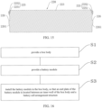
- the embodiments of the present application provide a method for producing a battery, including: providing a box body; providing a battery module, the battery module includes a battery cell arrangement structure and an end plate, the battery cell arrangement structure comprises a plurality of battery cells stacked upon each other, the end plate is fixedly connected to the battery cell arrangement structure, the box body includes a first wall and a second wall, the second wall is connected to the first wall and extends upward, the battery module is located above the first wall, and the end plate is arranged between the second wall and the battery cell arrangement structure, the end plate includes a first elastic support portion, the first elastic support portion is configured to be capable of abutting against the second wall and be pressed and deformed by the battery cell arrangement structure when the battery cell arrangement structure expands, to provide expansion space for the battery cell arrangement structure, the first elastic support portion is constructed as a sheet shape structure extending obliquely upward towards the second wall, wherein the box body further comprises a pair of third walls, the pair of third walls are connected to the first wall
- An application of a battery generally includes three levels: a battery cell, a battery module and a battery pack.
- the battery cell includes a positive electrode plate, a negative electrode plate, an electrolyte and a separator.
- the separator is arranged between the positive electrode plate and the negative electrode plate to prevent an internal short circuit.
- the battery cell can be divided into three types according to a packaging mode: a cylindrical battery cell, a square battery cell and a soft pack battery cell.
- the battery module refers to a single physical module including a plurality of battery cells to provide a higher voltage and/or capacity.
- the plurality of battery cells can be connected in series and/or in parallel via a bus bar, so as to be used in various applications, for example, in some high-power applications such as electric vehicles.
- the battery pack is constructed by assembling components such as a battery management system on the basis of one or more battery modules, and loading the components in a sealed box body, the sealed box body is then connected to power consumption devices such as the electric vehicles.
- the battery mentioned in the present application can be the battery pack.
- the battery module and the box body are rigidly connected with a fastener, and during expansion of the battery module, a part of expansion force can be released to a certain extent through local deformation of the end plate.
- a rigid connection is formed between the two. Therefore, the box body is bound to be affected during deformation of the end plate, which may cause the deformation of the box body.
- the local deformation of the end plate can be small, which is not conducive to providing sufficient expansion space for the battery module.
- the battery cell can still be pressed by an inner wall of the box body during the expansion, which may cause occurrence of a lithium evolution phenomenon, resulting in a shrinkage of battery capacity.
- some embodiments of the present application provide a battery 10.
- expansion space can be provided for a battery module 200 to release expansion force, which is conducive to decreasing a possibility of the occurrence of a lithium evolution caused by compression on the battery cell 211, and also decreasing a possibility of deformation of a box body 100 at the same time.
- the possibility of the deformation of the box body 100 can be reduced while providing the expansion space for the battery module 200.
- the embodiments of the present application provides a power consumption device using the battery 10 as a power supply, and the power consumption device can be, but is not limited to, a vehicle 1, a ship or an aircraft.
- the battery 10 described in the embodiments of the present application is applicable to various devices using batteries, such as mobile phones, notebook computers, battery carts, electric vehicles, ships, spacecrafts, electric toys and electric tools, etc.
- the spacecrafts include rockets, space shuttles and spaceships, etc.
- the electric toys include fixed or mobile electric toys, such as game consoles, electric vehicle toys, electric ship toys and electric airplane toys, etc.
- the electric tools include metal cutting power tools, grinding power tools, assembly power tools and railway power tools, such as electric drills, electric grinders, electric wrenches, electric screwdrivers, electric hammers, concrete vibrators, and electric planers.
- the battery 10 described in the embodiments of the present application is not only applicable to the power consumption device described above, but also applicable to all devices that use the battery 10.
- FIG. 1 is a structural schematic diagram of a vehicle 1 according to an embodiment of the present application.
- the vehicle 1 can be a fuel-powered vehicle, a gas-powered vehicle or a new energy vehicle, and the new energy vehicle can be a battery electric vehicle, a hybrid vehicle, an extended-range vehicle, or the like.
- the battery 10, a motor 20 and a controller 30 can be arranged in the vehicle 1, and the controller 30 is used to control the battery 10 to supply power to the motor 20, for example, the battery 10 is arranged at the bottom or the head of the vehicle 1.
- the battery 10 can be used to supply power to the vehicle 1, for example, the battery 10 can be used as an operation power supply of the vehicle 1 and is used for a circuit system of the vehicle 1, for example, for a working power demand of the vehicle 1 during startup, navigation and operation.
- the battery 10 can be used not only as the operation power supply of the vehicle 1 but also as a driving power supply of the vehicle 1, replacing or partially replacing fuel or natural gas to provide driving power for the vehicle 1.
- the vehicle can be powered by the battery 10 as shown in FIG. 2 .
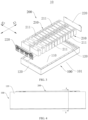
- the battery 10 includes the battery module 200 and the box body 100, and the battery module 200 is arranged in the box body 100.
- the battery module 200 includes a battery cell arrangement structure 210 and an end plate 220, the battery cell arrangement structure 210 can include a plurality of battery cells 211 stacked along a first direction A1, the end plate 220 is arranged between an inner wall of the box body 100 and the battery cell arrangement structure 210, and the end plate 220 is fixedly connected to the battery cell arrangement structure 210.
- the end plate 220 includes a first elastic support portion 224, and the first elastic support portion 224 is configured to be able to abut against the inner wall of the box body 100 and be pressed and deformed by the battery cell arrangement structure 210 when the battery cell arrangement structure 210 expands, so as to provide expansion space for the battery cell arrangement structure 210.
- the battery cell arrangement structure 210 since the battery cell arrangement structure 210 includes a plurality of battery cells 211 in the first direction A1, the battery module 200 mainly expands along the first direction A1 when expanding.
- the first elastic support portion 224 deforms itself to provide the expansion space and the deformation is reliable, which can provide the expansion space for the battery cell arrangement structure 210 in time (that is, provide the expansion space for the battery module 200), mainly providing the expansion space in the first direction, so as to release expansion force of the battery cell arrangement structure 210, and be capable of reducing the possibility of the deformation of the box body 100 caused by the expansion force, which improves installation and assembly reliability and a service life of the box body 100.
- the possibility of the occurrence of the lithium evolution of the battery cell 211 due to excessive extrusion force between the inner wall of the box body 100 and the end plate 220 can be reduced. Therefore, the possibility of the deformation of the box body 100 can be reduced while providing the expansion space for the battery module 200, which is conducive to a normal operation of the battery 10.
- the end plate 220 and the battery cell arrangement structure 210 can be fixedly connected in any suitable manner, for example, bonding, strap connection, or using an end side plate to connect the end plate 220 and the battery cell arrangement structure 210, and the embodiments of the present application are not limited thereto.
- the box body 100 can include a lower box body 101 and an upper cover body 102, the upper cover body 102 is sealed and covered on the lower box body 101, and the battery module 200 can be installed in the lower box body 101.
- the box body 100 includes a first wall 110 and a second wall 120, the second wall 120 is connected to the first wall 110 and extends upward, the battery module 200 is located above the first wall 110, that is, the first wall 110 is a bottom wall of the box body 100, the second wall 120 is a side wall connected to the bottom wall, the first wall 110 can be a bottom wall of the lower box body 101, and the second wall 120 can be a side wall of the lower box body 101.
- the end plate 220 is arranged between the second wall 120 and the battery cell arrangement structure 210.
- the first elastic support portion 224 is configured to be able to abut against the second wall 120 and be pressed and deformed by the battery cell arrangement structure 210 when the battery cell arrangement structure 210 expands.
- the expansion space is provided between the end plate 220 and the second wall 120 of the box body 100 for the battery cell arrangement structure 210, which can reduce the extrusion force of the battery module 200 on the second wall 120 of the box body 100.
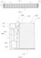
- the first elastic support portion 224 can be easily deformed when being compressed, as shown in FIG. 6 , in an embodiment of the present application, at least a part of the first elastic support portion 224 extends obliquely upward towards the second wall 120. On the basis of this, when the end plate 220 is compressed, the first elastic support portion 224 has an inclination angle, so that the first elastic support portion 224 is more easily deformed when being pressed by the second wall 120, which can provide the expansion space for the battery cell arrangement structure 210 in time.
- an upward inclination angle of the first elastic support portion 224 can be any angle as long as it can met deformation needs.
- the embodiments of the present application do not limit the upward inclination angle of the first elastic support portion 224.
- the end plate 220 further includes an end plate body 223, the end plate body 223 has a first surface 2231 facing the battery cell arrangement structure 210 and a second surface 2232 facing away from the battery cell arrangement structure 210, and the first elastic support portion 224 is arranged on the second surface 2232.
- the second surface 2232 is a large surface of the end plate body 223, which is convenient to arrange the first elastic support portion 224.
- the second surface 2232 is the large surface (the surface with the larger area), which is convenient to arrange more first elastic support portions 224, it is conducive to dispersing the expansion force of the battery cell arrangement structure 210, and reducing the possibility of the occurrence of the lithium evolution caused by the compression on the battery cell 211 due to the concentrated extrusion force.
- the first elastic support portion 224 can also be arranged on two side walls in a thickness direction (the first direction A1) of the end plate body 223, that is, arranged on a small surface (the surface with a smaller area) of the end plate body 223, and extend towards the second wall 120.
- an orthographic projection of the first elastic support portion 224 on a horizontal plane is a long-strip shape, a surface on which a long side of the long-strip shape is located is connected to the second surface 2232, and a surface on which the other long side of the long-strip shape is located is used to abut against the second wall 120.
- the first elastic support portion 224 is arranged on the second surface 2232 along the length direction of the end plate 220 (that is, a second direction A2, which intersects the first direction A1). In this way, it is conducive to dispersing the expansion force of the battery cell arrangement structure 210 in the length direction of the end plate 220.
- the first elastic support portion 224 can be formed as a sheet shape. That is, in the embodiment, the first elastic support portion 224 is constructed as a sheet shape structure extending obliquely upward.
- the embodiments of the present application do not limit a specific structure of the first elastic support portion 224.
- the first elastic support portion 224 can also be constructed as a horizontal protrusion extending along the first direction A1, and the first elastic support portion 224 is provided with a groove or other strength weakening structures to weaken strength of the first elastic support portion 224, so that the first elastic support portion 224 is easily deformed when being pressed by the second wall 120.
- the first elastic support portion 224 can also be a spring, one end of the spring is connected to (for example, welded) the second surface 2232, and the other end extends towards the second wall 120.
- the plurality of the first elastic support portions 224 are arranged at intervals on the second surface 2232 along the up and down direction, so as to facilitate uniform dispersion of the expansion force, and improve stress consistency of each place on a plane where the battery cell arrangement structure 210 is in contact with the end plate 220, which improves the stress consistency of the battery cell 211.
- the plurality of the first elastic support portions 224 can be arranged in a rectangular array on the second surface 2232, which is conducive to dispersing the expansion force transmitted from the battery cell arrangement structure 210 to the end plate 220, to further improve the stress consistency of each place of the battery cell arrangement structure 210 and improve the stress consistency of the battery cell 211.
- each first elastic support portion 224 extends in the length direction of the end plate body 223, and the extension of the first elastic support portions 224 in the length direction of the end plate body 223 is not interrupted.
- the end plate 220 of the battery module 200 is generally installed on a side wall of the box body 100 through a fastener (such as a locking bolt).
- a fastener such as a locking bolt
- a thickness size of the side wall of the box body is relatively large. Therefore, it is not conducive to increasing space of the box body 100 for accommodating the battery module 200, which reduces space utilization in the box body 100.
- a restraint surface 121 is arranged on the second wall 120, the restraint surface 121 is used to abut against the end plate 220 to restrict the end plate 220 from moving upward.
- the restraint surface 121 restricts the end plate 220 from freely moving upward, which ensures installation locations of the end plate 220 and the battery module 200 in the up and down direction (that is, a height direction of the end plate 220), and avoids affecting the normal operation of the battery module 200 due to an upward movement of the battery module 200.
- the bolt locking between the battery module 200 and the box body 100 can be omitted, which is conducive to reducing use of parts and increasing the space utilization in the box body 100. Moreover, the bolt locking is canceled, a rigid connection between the battery module 200 and the box body 100 is released, so the possibility of the deformation of the box body 100 can be reduced while providing the expansion space for the battery module 200, and at the same time, canceling the bolt locking simplifies the process, which improves assembly efficiency of the battery 10.
- the restraint surface 121 can be constructed by any suitable structure. As shown in FIG. 6 , in an embodiment of the present application, the second wall 120 is partially recessed towards a surface of the end plate 220 to form a groove, and an upper side wall of the groove is the restraint surface 121.
- the upper side wall of the groove constructs the restraint surface 121, which not only does not occupy the space of the box body 100 for accommodating the battery module 200, but also is conducive to lightweight of the box body 100.
- the end plate 220 is provided with a restraint protrusion 221, and an upper surface of the restraint protrusion 221 is used to abut against the restraint surface 121 to restrict the end plate 220 from moving upward.
- a manner that the restraint protrusion 221 abuts against and restrain the restraint surface 121 has advantages of a simple structure and a convenient installation of the battery module 200 in the box body 100 while implementing reliable restraint between the end plate 220 and the box body 100.
- the restraint protrusion 221 extends horizontally towards the second wall 120.
- a direction (upward) in which the restraint protrusion 221 may move is perpendicular to an extending direction, so that it is not easy to slide between the restraint protrusion 221 and the restraint surface 121, which can improve restraint reliability of the restraint protrusion 221 and the restraint surface 121.
- the restraint surface 121 can be a surface parallel to the horizontal plane. In this way, when the restraint protrusion 221 abuts against the restraint surface 121, the two surfaces are fully fitted, which further improves the restraint reliability of the restraint protrusion 221 and the restraint surface 121.
- the extrusion force can be applied to the battery module 200 to compress a length of the battery module 200 in the first direction A1; then the battery module 200 in a compressed state is placed in the box body 100 and disposed on the first wall 110; next, the extrusion force is removed to restore the length of the battery module 200, so that the restraint protrusion 221 of the end plate 220 moves to a lower part of the restraint surface 121.
- the upper surface of the restraint protrusion 221 has a gap with the restraint surface 121 in the up and down direction when the battery cell arrangement structure 210 is not expanded.
- the restraint surface 121 will not interfere with a horizontal movement of the restraint protrusion 221, which is conducive to the smooth movement of the restraint protrusion 221 to the lower part of the restraint surface 121.
- the restraint protrusion 221 also has a gap with the second wall 120 in a horizontal direction when the battery cell arrangement structure 210 is not expanded, so that the end plate 220 at least can move towards the second wall 120, so as to provide the expansion space for the battery cell arrangement structure 210.
- the movement of the restraint protrusion 221 towards the second wall 120 can be divided into two stages. In a first stage, the restraint protrusion 221 moves horizontally towards the second wall 120 until it abuts on the second wall 120. If the battery cell arrangement structure 210 continues to expand after the restraint protrusion 221 abuts on the second wall 120, then the end plate body 223 can be locally deformed, so as to continue to provide the expansion space.
- the restraint protrusion 221 can be arranged on the second surface 2232 of the end plate body 223.
- the second surface 2232 is the large surface (the surface with the larger area) of the end plate body 223, which is convenient to arrange the restraint protrusion 221.
- the second surface 2232 is the large surface, so it is convenient to arrange a longer restraint protrusion 221 along a length direction (a direction perpendicular to the first direction A1) of the end plate 220, so as to increase the restraint reliability of the battery module 200 in the box body 100 in the up and down direction as much as possible.
- the restraint protrusion 221 can also be arranged on two side surfaces in the thickness direction (the first direction A1) of the end plate body 223, that is, arranged on the small surface (the surface with the smaller area) of the end plate body 223, and extend towards the second wall 120.
- an orthographic projection of the restraint protrusion 221 on a level is a long-strip shape, a surface on which a long side of the long-strip shape is located is connected to the second surface 2232.
- the restraint protrusion 221 is the long-strip shape, which is conducive to increasing a contact area between the restraint protrusion 221 and the first restraint surface 121, so that it is conducive to enhancing the restraint effect of the restraint protrusion 221.
- the battery module 200 is bonded to the first wall 110 via glue.
- a lower end of the end plate 220 is also provided with an extension portion 227, which can play a role of blocking structural glue, and avoid the upward movement of the structural glue to a certain extent.
- an upper end of the end plate 220 is also provided with a clamping portion 222, which is used to facilitate an assembly tool to clamp the battery module 200 when the battery module 200 is loaded in the box body 100.
- the box body 100 can include a pair of second walls 120, the pair of second walls 120 are arranged opposite to each other along the first direction A1.
- the first elastic support portion 224 can abut against the second wall 120 when the battery cell arrangement structure 210 is not expanded, to implement a positioning of the battery module 200 in the first direction A1.
- the first elastic support portion 224 provides an installation positioning in the first direction A1 for the battery module 200, which ensures the installation reliability of the battery module 200 in the first direction A1.
- one end of the battery module 200 can abut against one of the second walls 120 via the first elastic support portion 224, and the other end is fixedly connected to the other second wall 120, or both ends of the battery module 200 abut against the corresponding second walls 120 via the first elastic support portion 224.
- the first elastic support portion 224 abuts against the second wall 120, which can mean that the first elastic support portion 224 is just in contact with the second wall 120 and the first elastic support portion 224 is in a undeformed state, or can mean that the first elastic support portion 224 abuts against the second wall 120 and is in a deformed state, and the embodiments of the present application are not limited thereto.
- the battery module 200 is in interference fit with the box body 100, and the first elastic support portion 224 is configured to absorb interference magnitude in the first direction A1 by producing elastic deformation. That is, in the embodiment, when the battery cell arrangement structure 210 is not expanded, the first elastic support portion 224 abuts against the second wall 120 and is in the deformed state.
- this arrangement also has at least the following two advantages: first, after the battery module 200 is assembled in place, the first elastic support portion 224 provides assembly allowance in the first direction A1 for the battery module 200, so that a size error of the battery module 200 in the first direction A1 can be offset by the deformation of the first elastic support portion 224, for example, when a size of the battery module 200 in the first direction A1 is larger than an installation size of the box body 100 in a corresponding direction, the battery module 200 can be smoothly loaded in the box body 100 through the deformation of the first elastic support portion 224, and thus requirements on processing and assembly accuracy of the battery module 200 in the first direction A1 are reduced; second, when the battery module 200 is assembled in place, since the first elastic support portion 224 is in the deformed state, reaction force of the second wall 120 can be sent to the battery cell arrangement structure 210, as the battery cell 211 is subjected to a certain amount of pressure, it is conducive to ensuring
- the box body 100 further includes a pair of third walls 130, the pair of third walls 130 are connected to the first wall 110 and extend upward, the pair of third walls 130 are arranged opposite to each other along a second direction A2, and the second direction A2 intersects the first direction A1.
- the second direction A2 can be perpendicular to the first direction A1, and the second direction A2 can be the length direction of the end plate 220.
- the end plate 220 further includes a second elastic support portion 225, and the second elastic support portion 225 is used to abut against the third wall 130, to implement a positioning of the battery module 200 in the second direction A2.
- the second elastic support portion 225 abuts against the third wall 130 to provide an installation positioning in the second direction A2 for the battery module 200, which ensures the installation reliability of the battery module 200 in the second direction A2.
- the second elastic support portion 225 abuts against the third wall 130, which can mean that the second elastic support portion 225 is just in the contact with the third wall 130 and the second elastic support portion 225 is in the undeformed state, or can mean that the second elastic support portion 225 abuts against the third wall 130 and is in the deformed state, and the embodiments of the present application are not limited thereto.
- the battery module 200 is in interference fit with the box body 100, and the second elastic support portion 224 is configured to absorb interference magnitude in the second direction A2 by producing elastic deformation. That is, in the embodiment, when the battery cell arrangement structure 210 is not expanded, the second elastic support portion 225 abuts against the second wall 130 and is in the deformed state.
- this arrangement also has at least the following two advantages: first, after the battery module 200 is assembled in place, the second elastic support portion 225 provides the assembly allowance in the second direction A2 to the battery module 200, so that the size error of the battery module 200 in the second direction A2 can be offset by the deformation of the second elastic support portion 225, for example, when the size of the battery module 200 in the second direction A2 is larger than the installation size in of the box body 100 in a corresponding direction, the battery module 200 can be smoothly loaded in the box body 100 through the deformation of the second elastic support portion 225, and thus the requirements on the processing and assembly accuracy of the battery module 200 in the second direction A2 are reduced; second, when the battery module 200 is assembled in place, since the second elastic support portion 225 is in the deformed state, the reaction force of the third wall 130 can be sent to the battery cell arrangement structure 210, as the battery cell 211 is subjected to the certain amount of the pressure, it is conducive
- the second elastic support portion 225 can be arranged between the battery module 200 and one of the third walls 130, that is, the second elastic support portion 225 is only arranged on one side of the end plate 220, or the second elastic support portion 225 can be arranged between the battery module 200 and the pair of third walls 130, that is, the second elastic support portion 225 is arranged on both opposite sides of the end plate 220.
- the second elastic support portion 225 is arranged on both opposite sides of the end plate body 223 in the second direction A2, that is, the end plate body 223 is provided with the second elastic support portion 225 on the both opposite sides along the second direction A2.
- a projection of an accommodating cavity of the box body 100 for accommodating the battery module 200 on the horizontal plane is a rectangle
- the first direction A1 is a length direction of the rectangle
- the second direction A2 is a width direction of the rectangle.
- the battery module 200 is provided with the first elastic support portion 224 and the second elastic support portion 225 in the first direction A1 and the second direction A2, respectively, which can provide the reliable installation positioning for the battery module 200.
- the projection of the accommodating cavity of the box body 100 for accommodating the battery module 200 on the horizontal plane can be other shapes, such as a combination of the rectangle and a trapezoid.
- the second elastic support portion 225 extends upward from the end plate body 223 towards the second wall 130. In this way, an upward extending part of the second elastic support portion 225 can abut against the third wall 130 to implement the installation positioning of the second elastic support portion 225 and the third wall 130.
- the second elastic support portion 225 extends obliquely upward, which is conducive to the second elastic support portion 225 being pressed and deformed by the third wall 130.
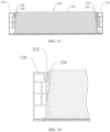
- the second elastic support portion 225 includes a first section 2251 and a second section 2252, the first section 2251 extends obliquely upward from the end plate body 223 towards the third wall 130, the second section 2252 extends upward from an end of the first section 2251 away from the end plate body 223, and the second section is used to abut against the third wall 130.
- the first section 2251 is arranged obliquely upward, which can play a certain guide role.
- the second section 2252 extends along the up and down direction, and can form surface contact with the third wall 130, which is conducive to extrusion and fitting of the two. Moreover, the second section 2252 has a gap with the end plate body 223, which is conducive to the deformation of the second section 2252 when being pressed by the third wall 130.
- the second elastic support portion 225 can be constructed as an elastic long strip extending along the up and down direction.
- the end plate 220 further includes a guide portion 226, the guide portion 226 is located below the second elastic support portion 225, the guide portion 226 has a guide chamfer 2261, and the guide chamfer 2261 is used to guide when the end plate 220 is loaded in the box body 100.
- the guide portion can have a gap with the third wall 130.
- a height of the guide portion protruding from the end plate body 223 in the second direction A2 is smaller than a height of the second elastic support portion 225 protruding from the end plate body 223 in the second direction A2.
- a lower end of the battery cell arrangement structure 210 can be attached to the first wall 110, and a lower end of the end plate 220 has a gap with the first wall 110, so as to ensure contact between the battery cell arrangement structure 210 and the first wall 110.
- attach in the above can mean that the lower end of the battery cell arrangement structure 210 is in contact with but not connected to the first wall 110, or can mean that the lower end of the battery cell arrangement structure 210 is in contact with and connected to the first wall 110, for example, the two are bonded via the glue.
- a method for producing a battery 10 is provided, for example, the method for producing the battery 10 mentioned above, and the method includes the following steps:
- the battery module 200 and the box body 100 can be the battery module 200 and the box body 100 mentioned above.
Landscapes
- Chemical & Material Sciences (AREA)
- Chemical Kinetics & Catalysis (AREA)
- Electrochemistry (AREA)
- General Chemical & Material Sciences (AREA)
- Engineering & Computer Science (AREA)
- Aviation & Aerospace Engineering (AREA)
- Battery Mounting, Suspending (AREA)
Applications Claiming Priority (1)
| Application Number | Priority Date | Filing Date | Title |
|---|---|---|---|
| PCT/CN2020/135942 WO2022120848A1 (zh) | 2020-12-11 | 2020-12-11 | 电池、用电装置及制备电池的方法 |
Publications (4)
| Publication Number | Publication Date |
|---|---|
| EP4050705A4 EP4050705A4 (en) | 2022-08-31 |
| EP4050705A1 EP4050705A1 (en) | 2022-08-31 |
| EP4050705B1 true EP4050705B1 (en) | 2024-04-10 |
| EP4050705C0 EP4050705C0 (en) | 2024-04-10 |
Family
ID=81941946
Family Applications (1)
| Application Number | Title | Priority Date | Filing Date |
|---|---|---|---|
| EP20934237.7A Active EP4050705B1 (en) | 2020-12-11 | 2020-12-11 | Battery, power utilization apparatus, and battery manufacturing method |
Country Status (7)
| Country | Link |
|---|---|
| US (3) | US12407057B2 (es) |
| EP (1) | EP4050705B1 (es) |
| JP (1) | JP7511666B2 (es) |
| KR (1) | KR102799457B1 (es) |
| CN (1) | CN115868071B (es) |
| ES (1) | ES2983049T3 (es) |
| WO (1) | WO2022120848A1 (es) |
Families Citing this family (16)
| Publication number | Priority date | Publication date | Assignee | Title |
|---|---|---|---|---|
| JP7700604B2 (ja) * | 2021-09-24 | 2025-07-01 | トヨタ自動車株式会社 | 蓄電装置 |
| US12603373B2 (en) | 2022-03-23 | 2026-04-14 | Ford Global Technologies, Llc | Traction battery pack assembling method |
| US12479327B2 (en) | 2022-03-23 | 2025-11-25 | Ford Global Technologies, Llc | Traction battery pack cell stack removal method and battery pack assembly |
| US12374750B2 (en) | 2022-03-23 | 2025-07-29 | Ford Global Technologies, Llc | Traction battery pack assembling method |
| US12506215B2 (en) | 2022-03-23 | 2025-12-23 | Ford Global Technologies, Llc | Enclosure cover attachment configurations for traction battery packs with cell-to-pack battery systems |
| US12275298B2 (en) | 2022-03-23 | 2025-04-15 | Ford Global Technologies, Llc | Traction battery packs with cell-to-pack battery systems housed within irregularly shaped enclosures |
| US12525637B2 (en) | 2022-03-23 | 2026-01-13 | Ford Global Technologies, Llc | Traction battery pack assembling method |
| US12230826B2 (en) | 2022-03-23 | 2025-02-18 | Ford Global Technologies, Llc | Methods for assembling traction battery packs |
| US12567642B2 (en) | 2022-03-23 | 2026-03-03 | Ford Global Technologies, Llc | Shim systems for traction battery packs |
| US12424695B2 (en) | 2022-03-23 | 2025-09-23 | Ford Global Technologies, Llc | Retention assemblies for traction battery packs with cell-to-pack battery systems |
| CN116231169A (zh) * | 2022-12-29 | 2023-06-06 | 远景能源有限公司 | 一种热平衡电池包和电池包储能系统 |
| CN116435680A (zh) * | 2023-04-06 | 2023-07-14 | 安徽吉厚智能科技有限公司 | 一种电池端板 |
| CN116799415B (zh) * | 2023-08-18 | 2024-01-02 | 欣旺达动力科技股份有限公司 | 一种电池包及用电设备 |
| CN119040959B (zh) * | 2024-08-29 | 2025-03-14 | 深圳市润世华氢能源有限公司 | 一种水电解制氢用自动化监控系统 |
| CN119627340A (zh) * | 2024-10-12 | 2025-03-14 | 中创新航科技集团股份有限公司 | 电池包及用电设备 |
| CN120127280B (zh) * | 2025-04-28 | 2025-11-21 | 广州宇成智能科技有限公司 | 一种侧面底部双通道液冷浸没式电池箱 |
Family Cites Families (19)
| Publication number | Priority date | Publication date | Assignee | Title |
|---|---|---|---|---|
| JP2013051100A (ja) * | 2011-08-31 | 2013-03-14 | Nissan Motor Co Ltd | バッテリ温調用モジュール |
| JP6357439B2 (ja) * | 2015-03-31 | 2018-07-11 | 太陽誘電株式会社 | 蓄電モジュール |
| KR101979888B1 (ko) * | 2015-08-19 | 2019-05-17 | 주식회사 엘지화학 | 배터리 모듈, 배터리 모듈을 포함하는 배터리 팩 및 배터리 팩을 포함하는 자동차 |
| CN205159404U (zh) * | 2015-12-02 | 2016-04-13 | 北京长城华冠汽车科技股份有限公司 | 一种锂离子电池模组、锂离子电池箱和汽车 |
| KR102154361B1 (ko) * | 2015-12-09 | 2020-09-09 | 주식회사 엘지화학 | 엔드 플레이트의 구조가 개선된 배터리 모듈 및 이를 위한 엔드 플레이트 부재 |
| CN205303550U (zh) * | 2015-12-30 | 2016-06-08 | 宁德时代新能源科技股份有限公司 | 电池模组用框架 |
| CN205723711U (zh) * | 2016-06-21 | 2016-11-23 | 宁德时代新能源科技股份有限公司 | 一种电池模组 |
| CN206250253U (zh) * | 2016-12-27 | 2017-06-13 | 宁德时代新能源科技股份有限公司 | 电池模组端板及电池模组 |
| US11289764B2 (en) * | 2017-08-29 | 2022-03-29 | Panasonic Intellectual Property Management Co., Ltd. | Battery pack |
| PL3688826T3 (pl) * | 2017-09-29 | 2025-03-31 | Robert Bosch Gmbh | Pakiet akumulatorowy posiadający utwierdzenie ogniw |
| CN207250612U (zh) * | 2017-09-29 | 2018-04-17 | 宁德时代新能源科技股份有限公司 | 端板及电池包 |
| JP7174923B2 (ja) | 2018-01-17 | 2022-11-18 | パナソニックIpマネジメント株式会社 | 蓄電装置 |
| KR102250204B1 (ko) * | 2018-03-07 | 2021-05-10 | 주식회사 엘지화학 | 배터리 모듈, 이러한 배터리 모듈을 포함하는 배터리 팩 및 이러한 배터리 팩을 포함하는 자동차 |
| KR102506446B1 (ko) * | 2018-03-07 | 2023-03-06 | 삼성전자주식회사 | 배터리 하우징 구조체 및 이를 적용한 배터리 장치 |
| US10601006B2 (en) | 2018-04-05 | 2020-03-24 | Ford Global Technologies, Llc | Method and battery assembly for electrified vehicle |
| CN209447945U (zh) * | 2018-12-30 | 2019-09-27 | 宁德时代新能源科技股份有限公司 | 一种电池包 |
| KR102298105B1 (ko) * | 2019-01-08 | 2021-09-03 | 주식회사 엘지에너지솔루션 | 스웰링 게이지를 구비한 배터리 모듈 및 이를 포함하는 배터리 팩 |
| CN209312858U (zh) * | 2019-01-31 | 2019-08-27 | 宁德时代新能源科技股份有限公司 | 一种电池模组及其端板组件 |
| CN113508490B (zh) * | 2019-02-27 | 2023-06-23 | 本田技研工业株式会社 | 端板的固定结构及电池装置 |
-
2020
- 2020-12-11 WO PCT/CN2020/135942 patent/WO2022120848A1/zh not_active Ceased
- 2020-12-11 CN CN202080102972.5A patent/CN115868071B/zh active Active
- 2020-12-11 KR KR1020227034019A patent/KR102799457B1/ko active Active
- 2020-12-11 ES ES20934237T patent/ES2983049T3/es active Active
- 2020-12-11 JP JP2022561164A patent/JP7511666B2/ja active Active
- 2020-12-11 EP EP20934237.7A patent/EP4050705B1/en active Active
-
2021
- 2021-11-17 US US17/528,639 patent/US12407057B2/en active Active
-
2025
- 2025-07-28 US US19/282,875 patent/US20250357610A1/en active Pending
- 2025-07-29 US US19/283,832 patent/US20250357611A1/en active Pending
Also Published As
| Publication number | Publication date |
|---|---|
| US20220190423A1 (en) | 2022-06-16 |
| EP4050705A4 (en) | 2022-08-31 |
| US20250357610A1 (en) | 2025-11-20 |
| EP4050705A1 (en) | 2022-08-31 |
| KR102799457B1 (ko) | 2025-04-22 |
| JP2023520918A (ja) | 2023-05-22 |
| WO2022120848A1 (zh) | 2022-06-16 |
| US20250357611A1 (en) | 2025-11-20 |
| JP7511666B2 (ja) | 2024-07-05 |
| CN115868071B (zh) | 2025-02-18 |
| KR20220145401A (ko) | 2022-10-28 |
| ES2983049T3 (es) | 2024-10-21 |
| CN115868071A (zh) | 2023-03-28 |
| US12407057B2 (en) | 2025-09-02 |
| EP4050705C0 (en) | 2024-04-10 |
Similar Documents
| Publication | Publication Date | Title |
|---|---|---|
| EP4050705B1 (en) | Battery, power utilization apparatus, and battery manufacturing method | |
| EP4050706B1 (en) | Battery, power consumption apparatus, and battery preparation method | |
| EP4044345B1 (en) | Battery, electric apparatus, and method for manufacturing battery | |
| CN116325302B (zh) | 电池以及用电装置 | |
| CN116960561A (zh) | 电池和用电设备 | |
| CN219795807U (zh) | 螺栓、电路板组件、电池及用电装置 | |
| CN222654174U (zh) | 电池及用电设备 | |
| CN223066350U (zh) | 电池装置及用电装置 | |
| CN222735204U (zh) | 电池及用电设备 | |
| CN220492047U (zh) | 电池及用电装置 | |
| CN222126838U (zh) | 电池及用电装置 | |
| CN223828568U (zh) | 电池装置以及用电装置 | |
| CN221057523U (zh) | 一种电池及用电装置 | |
| CN223843080U (zh) | 电池装置以及用电设备 | |
| CN220492053U (zh) | 电池箱、电池及用电设备 | |
| CN121011771A (zh) | 电池装置及用电设备 | |
| CN117178424A (zh) | 电池及其制造方法和制造设备以及用电装置 |
Legal Events
| Date | Code | Title | Description |
|---|---|---|---|
| STAA | Information on the status of an ep patent application or granted ep patent |
Free format text: STATUS: UNKNOWN |
|
| STAA | Information on the status of an ep patent application or granted ep patent |
Free format text: STATUS: THE INTERNATIONAL PUBLICATION HAS BEEN MADE |
|
| PUAI | Public reference made under article 153(3) epc to a published international application that has entered the european phase |
Free format text: ORIGINAL CODE: 0009012 |
|
| STAA | Information on the status of an ep patent application or granted ep patent |
Free format text: STATUS: REQUEST FOR EXAMINATION WAS MADE |
|
| 17P | Request for examination filed |
Effective date: 20211111 |
|
| A4 | Supplementary search report drawn up and despatched |
Effective date: 20220620 |
|
| AK | Designated contracting states |
Kind code of ref document: A1 Designated state(s): AL AT BE BG CH CY CZ DE DK EE ES FI FR GB GR HR HU IE IS IT LI LT LU LV MC MK MT NL NO PL PT RO RS SE SI SK SM TR |
|
| STAA | Information on the status of an ep patent application or granted ep patent |
Free format text: STATUS: EXAMINATION IS IN PROGRESS |
|
| 17Q | First examination report despatched |
Effective date: 20221208 |
|
| GRAP | Despatch of communication of intention to grant a patent |
Free format text: ORIGINAL CODE: EPIDOSNIGR1 |
|
| STAA | Information on the status of an ep patent application or granted ep patent |
Free format text: STATUS: GRANT OF PATENT IS INTENDED |
|
| GRAS | Grant fee paid |
Free format text: ORIGINAL CODE: EPIDOSNIGR3 |
|
| GRAA | (expected) grant |
Free format text: ORIGINAL CODE: 0009210 |
|
| STAA | Information on the status of an ep patent application or granted ep patent |
Free format text: STATUS: THE PATENT HAS BEEN GRANTED |
|
| DAV | Request for validation of the european patent (deleted) | ||
| DAX | Request for extension of the european patent (deleted) | ||
| INTG | Intention to grant announced |
Effective date: 20240214 |
|
| AK | Designated contracting states |
Kind code of ref document: B1 Designated state(s): AL AT BE BG CH CY CZ DE DK EE ES FI FR GB GR HR HU IE IS IT LI LT LU LV MC MK MT NL NO PL PT RO RS SE SI SK SM TR |
|
| REG | Reference to a national code |
Ref country code: GB Ref legal event code: FG4D |
|
| REG | Reference to a national code |
Ref country code: CH Ref legal event code: EP |
|
| REG | Reference to a national code |
Ref country code: DE Ref legal event code: R096 Ref document number: 602020028961 Country of ref document: DE |
|
| REG | Reference to a national code |
Ref country code: IE Ref legal event code: FG4D |
|
| U01 | Request for unitary effect filed |
Effective date: 20240507 |
|
| U07 | Unitary effect registered |
Designated state(s): AT BE BG DE DK EE FI FR IT LT LU LV MT NL PT SE SI Effective date: 20240516 |
|
| REG | Reference to a national code |
Ref country code: GB Ref legal event code: 732E Free format text: REGISTERED BETWEEN 20240822 AND 20240828 |
|
| RAP2 | Party data changed (patent owner data changed or rights of a patent transferred) |
Owner name: CONTEMPORARY AMPEREX TECHNOLOGY(HONG KONG) LIMITED |
|
| U1K | Transfer of rights of the unitary patent after the registration of the unitary effect |
Owner name: CONTEMPORARY AMPEREX TECHNOLOGY(HONG KONG) LIMITED; HK |
|
| PG25 | Lapsed in a contracting state [announced via postgrant information from national office to epo] |
Ref country code: IS Free format text: LAPSE BECAUSE OF FAILURE TO SUBMIT A TRANSLATION OF THE DESCRIPTION OR TO PAY THE FEE WITHIN THE PRESCRIBED TIME-LIMIT Effective date: 20240810 |
|
| PG25 | Lapsed in a contracting state [announced via postgrant information from national office to epo] |
Ref country code: HR Free format text: LAPSE BECAUSE OF FAILURE TO SUBMIT A TRANSLATION OF THE DESCRIPTION OR TO PAY THE FEE WITHIN THE PRESCRIBED TIME-LIMIT Effective date: 20240410 |
|
| PG25 | Lapsed in a contracting state [announced via postgrant information from national office to epo] |
Ref country code: GR Free format text: LAPSE BECAUSE OF FAILURE TO SUBMIT A TRANSLATION OF THE DESCRIPTION OR TO PAY THE FEE WITHIN THE PRESCRIBED TIME-LIMIT Effective date: 20240711 |
|
| REG | Reference to a national code |
Ref country code: ES Ref legal event code: FG2A Ref document number: 2983049 Country of ref document: ES Kind code of ref document: T3 Effective date: 20241021 |
|
| PG25 | Lapsed in a contracting state [announced via postgrant information from national office to epo] |
Ref country code: PL Free format text: LAPSE BECAUSE OF FAILURE TO SUBMIT A TRANSLATION OF THE DESCRIPTION OR TO PAY THE FEE WITHIN THE PRESCRIBED TIME-LIMIT Effective date: 20240410 |
|
| PG25 | Lapsed in a contracting state [announced via postgrant information from national office to epo] |
Ref country code: PL Free format text: LAPSE BECAUSE OF FAILURE TO SUBMIT A TRANSLATION OF THE DESCRIPTION OR TO PAY THE FEE WITHIN THE PRESCRIBED TIME-LIMIT Effective date: 20240410 Ref country code: NO Free format text: LAPSE BECAUSE OF FAILURE TO SUBMIT A TRANSLATION OF THE DESCRIPTION OR TO PAY THE FEE WITHIN THE PRESCRIBED TIME-LIMIT Effective date: 20240710 Ref country code: IS Free format text: LAPSE BECAUSE OF FAILURE TO SUBMIT A TRANSLATION OF THE DESCRIPTION OR TO PAY THE FEE WITHIN THE PRESCRIBED TIME-LIMIT Effective date: 20240810 Ref country code: HR Free format text: LAPSE BECAUSE OF FAILURE TO SUBMIT A TRANSLATION OF THE DESCRIPTION OR TO PAY THE FEE WITHIN THE PRESCRIBED TIME-LIMIT Effective date: 20240410 Ref country code: GR Free format text: LAPSE BECAUSE OF FAILURE TO SUBMIT A TRANSLATION OF THE DESCRIPTION OR TO PAY THE FEE WITHIN THE PRESCRIBED TIME-LIMIT Effective date: 20240711 Ref country code: RS Free format text: LAPSE BECAUSE OF FAILURE TO SUBMIT A TRANSLATION OF THE DESCRIPTION OR TO PAY THE FEE WITHIN THE PRESCRIBED TIME-LIMIT Effective date: 20240710 |
|
| REG | Reference to a national code |
Ref country code: DE Ref legal event code: R097 Ref document number: 602020028961 Country of ref document: DE |
|
| U20 | Renewal fee for the european patent with unitary effect paid |
Year of fee payment: 5 Effective date: 20241213 |
|
| PG25 | Lapsed in a contracting state [announced via postgrant information from national office to epo] |
Ref country code: CZ Free format text: LAPSE BECAUSE OF FAILURE TO SUBMIT A TRANSLATION OF THE DESCRIPTION OR TO PAY THE FEE WITHIN THE PRESCRIBED TIME-LIMIT Effective date: 20240410 |
|
| PG25 | Lapsed in a contracting state [announced via postgrant information from national office to epo] |
Ref country code: RO Free format text: LAPSE BECAUSE OF FAILURE TO SUBMIT A TRANSLATION OF THE DESCRIPTION OR TO PAY THE FEE WITHIN THE PRESCRIBED TIME-LIMIT Effective date: 20240410 Ref country code: SK Free format text: LAPSE BECAUSE OF FAILURE TO SUBMIT A TRANSLATION OF THE DESCRIPTION OR TO PAY THE FEE WITHIN THE PRESCRIBED TIME-LIMIT Effective date: 20240410 |
|
| PG25 | Lapsed in a contracting state [announced via postgrant information from national office to epo] |
Ref country code: SM Free format text: LAPSE BECAUSE OF FAILURE TO SUBMIT A TRANSLATION OF THE DESCRIPTION OR TO PAY THE FEE WITHIN THE PRESCRIBED TIME-LIMIT Effective date: 20240410 |
|
| PG25 | Lapsed in a contracting state [announced via postgrant information from national office to epo] |
Ref country code: SM Free format text: LAPSE BECAUSE OF FAILURE TO SUBMIT A TRANSLATION OF THE DESCRIPTION OR TO PAY THE FEE WITHIN THE PRESCRIBED TIME-LIMIT Effective date: 20240410 Ref country code: SK Free format text: LAPSE BECAUSE OF FAILURE TO SUBMIT A TRANSLATION OF THE DESCRIPTION OR TO PAY THE FEE WITHIN THE PRESCRIBED TIME-LIMIT Effective date: 20240410 Ref country code: RO Free format text: LAPSE BECAUSE OF FAILURE TO SUBMIT A TRANSLATION OF THE DESCRIPTION OR TO PAY THE FEE WITHIN THE PRESCRIBED TIME-LIMIT Effective date: 20240410 Ref country code: CZ Free format text: LAPSE BECAUSE OF FAILURE TO SUBMIT A TRANSLATION OF THE DESCRIPTION OR TO PAY THE FEE WITHIN THE PRESCRIBED TIME-LIMIT Effective date: 20240410 |
|
| PLBE | No opposition filed within time limit |
Free format text: ORIGINAL CODE: 0009261 |
|
| STAA | Information on the status of an ep patent application or granted ep patent |
Free format text: STATUS: NO OPPOSITION FILED WITHIN TIME LIMIT |
|
| 26N | No opposition filed |
Effective date: 20250113 |
|
| PG25 | Lapsed in a contracting state [announced via postgrant information from national office to epo] |
Ref country code: MC Free format text: LAPSE BECAUSE OF FAILURE TO SUBMIT A TRANSLATION OF THE DESCRIPTION OR TO PAY THE FEE WITHIN THE PRESCRIBED TIME-LIMIT Effective date: 20240410 |
|
| REG | Reference to a national code |
Ref country code: CH Ref legal event code: PL |
|
| PG25 | Lapsed in a contracting state [announced via postgrant information from national office to epo] |
Ref country code: CH Free format text: LAPSE BECAUSE OF NON-PAYMENT OF DUE FEES Effective date: 20241231 |
|
| PG25 | Lapsed in a contracting state [announced via postgrant information from national office to epo] |
Ref country code: IE Free format text: LAPSE BECAUSE OF NON-PAYMENT OF DUE FEES Effective date: 20241211 |
|
| PGFP | Annual fee paid to national office [announced via postgrant information from national office to epo] |
Ref country code: GB Payment date: 20251211 Year of fee payment: 6 |
|
| U20 | Renewal fee for the european patent with unitary effect paid |
Year of fee payment: 6 Effective date: 20251217 |
|
| PGFP | Annual fee paid to national office [announced via postgrant information from national office to epo] |
Ref country code: ES Payment date: 20260105 Year of fee payment: 6 |