EP4050676A1 - Negative electrode sheet, electrochemical device comprising negative electrode sheet, and electronic device - Google Patents
Negative electrode sheet, electrochemical device comprising negative electrode sheet, and electronic device Download PDFInfo
- Publication number
- EP4050676A1 EP4050676A1 EP20938503.8A EP20938503A EP4050676A1 EP 4050676 A1 EP4050676 A1 EP 4050676A1 EP 20938503 A EP20938503 A EP 20938503A EP 4050676 A1 EP4050676 A1 EP 4050676A1
- Authority
- EP
- European Patent Office
- Prior art keywords
- silicon
- negative electrode
- based particles
- electrode plate
- lithium
- Prior art date
- Legal status (The legal status is an assumption and is not a legal conclusion. Google has not performed a legal analysis and makes no representation as to the accuracy of the status listed.)
- Pending
Links
- 239000011856 silicon-based particle Substances 0.000 claims abstract description 135
- 239000007773 negative electrode material Substances 0.000 claims abstract description 45
- OKTJSMMVPCPJKN-UHFFFAOYSA-N Carbon Chemical compound [C] OKTJSMMVPCPJKN-UHFFFAOYSA-N 0.000 claims abstract description 33
- XUIMIQQOPSSXEZ-UHFFFAOYSA-N Silicon Chemical compound [Si] XUIMIQQOPSSXEZ-UHFFFAOYSA-N 0.000 claims abstract description 33
- 229910052710 silicon Inorganic materials 0.000 claims abstract description 33
- 239000010703 silicon Substances 0.000 claims abstract description 33
- 239000002245 particle Substances 0.000 claims abstract description 31
- 229910002804 graphite Inorganic materials 0.000 claims abstract description 15
- 239000010439 graphite Substances 0.000 claims abstract description 15
- 239000003575 carbonaceous material Substances 0.000 claims description 26
- 238000012360 testing method Methods 0.000 claims description 26
- VNWKTOKETHGBQD-UHFFFAOYSA-N methane Chemical compound C VNWKTOKETHGBQD-UHFFFAOYSA-N 0.000 claims description 9
- 229910052799 carbon Inorganic materials 0.000 claims description 8
- 229910021389 graphene Inorganic materials 0.000 claims description 7
- 229920000049 Carbon (fiber) Polymers 0.000 claims description 5
- 239000004917 carbon fiber Substances 0.000 claims description 5
- 238000001237 Raman spectrum Methods 0.000 claims description 4
- 229910003481 amorphous carbon Inorganic materials 0.000 claims description 4
- 239000002041 carbon nanotube Substances 0.000 claims description 4
- 238000001069 Raman spectroscopy Methods 0.000 claims description 3
- 229910021393 carbon nanotube Inorganic materials 0.000 claims description 3
- 239000011852 carbon nanoparticle Substances 0.000 claims description 2
- 230000001351 cycling effect Effects 0.000 abstract description 42
- 230000008961 swelling Effects 0.000 abstract description 26
- 239000011148 porous material Substances 0.000 abstract description 25
- 229910052744 lithium Inorganic materials 0.000 abstract description 23
- WHXSMMKQMYFTQS-UHFFFAOYSA-N Lithium Chemical compound [Li] WHXSMMKQMYFTQS-UHFFFAOYSA-N 0.000 abstract description 21
- 238000009830 intercalation Methods 0.000 abstract description 15
- 230000002687 intercalation Effects 0.000 abstract description 15
- HBBGRARXTFLTSG-UHFFFAOYSA-N Lithium ion Chemical compound [Li+] HBBGRARXTFLTSG-UHFFFAOYSA-N 0.000 description 63
- 229910001416 lithium ion Inorganic materials 0.000 description 63
- 239000010410 layer Substances 0.000 description 57
- 238000002360 preparation method Methods 0.000 description 41
- 230000000052 comparative effect Effects 0.000 description 40
- 239000002109 single walled nanotube Substances 0.000 description 36
- -1 polytetrafluoroethylene ethylene Polymers 0.000 description 28
- 239000011734 sodium Substances 0.000 description 24
- 239000002033 PVDF binder Substances 0.000 description 14
- 239000011244 liquid electrolyte Substances 0.000 description 14
- 229920002981 polyvinylidene fluoride Polymers 0.000 description 14
- 239000002270 dispersing agent Substances 0.000 description 13
- 239000011230 binding agent Substances 0.000 description 11
- 238000000576 coating method Methods 0.000 description 11
- 238000000034 method Methods 0.000 description 11
- 239000002002 slurry Substances 0.000 description 11
- 229920000642 polymer Polymers 0.000 description 10
- 229920000036 polyvinylpyrrolidone Polymers 0.000 description 10
- 239000001267 polyvinylpyrrolidone Substances 0.000 description 10
- 235000013855 polyvinylpyrrolidone Nutrition 0.000 description 10
- 239000007774 positive electrode material Substances 0.000 description 10
- 239000011248 coating agent Substances 0.000 description 9
- 239000000463 material Substances 0.000 description 9
- 229920002125 Sokalan® Polymers 0.000 description 8
- 230000002579 anti-swelling effect Effects 0.000 description 8
- 230000014759 maintenance of location Effects 0.000 description 8
- 239000002048 multi walled nanotube Substances 0.000 description 8
- 239000005543 nano-size silicon particle Substances 0.000 description 7
- 239000002861 polymer material Substances 0.000 description 7
- 238000012545 processing Methods 0.000 description 7
- 239000007787 solid Substances 0.000 description 7
- 239000000758 substrate Substances 0.000 description 7
- 239000004698 Polyethylene Substances 0.000 description 6
- 239000004743 Polypropylene Substances 0.000 description 6
- 239000001768 carboxy methyl cellulose Substances 0.000 description 6
- 239000002131 composite material Substances 0.000 description 6
- 230000003090 exacerbative effect Effects 0.000 description 6
- 239000012528 membrane Substances 0.000 description 6
- 229920000058 polyacrylate Polymers 0.000 description 6
- 239000004584 polyacrylic acid Substances 0.000 description 6
- 229920000573 polyethylene Polymers 0.000 description 6
- 229920001155 polypropylene Polymers 0.000 description 6
- 239000000843 powder Substances 0.000 description 6
- 230000008569 process Effects 0.000 description 6
- 239000000243 solution Substances 0.000 description 6
- XLYOFNOQVPJJNP-UHFFFAOYSA-N water Chemical compound O XLYOFNOQVPJJNP-UHFFFAOYSA-N 0.000 description 6
- KMTRUDSVKNLOMY-UHFFFAOYSA-N Ethylene carbonate Chemical compound O=C1OCCO1 KMTRUDSVKNLOMY-UHFFFAOYSA-N 0.000 description 5
- 239000004642 Polyimide Substances 0.000 description 5
- DPXJVFZANSGRMM-UHFFFAOYSA-N acetic acid;2,3,4,5,6-pentahydroxyhexanal;sodium Chemical compound [Na].CC(O)=O.OCC(O)C(O)C(O)C(O)C=O DPXJVFZANSGRMM-UHFFFAOYSA-N 0.000 description 5
- 230000008859 change Effects 0.000 description 5
- 239000008367 deionised water Substances 0.000 description 5
- 229910021641 deionized water Inorganic materials 0.000 description 5
- 239000011888 foil Substances 0.000 description 5
- 239000007789 gas Substances 0.000 description 5
- 229920001721 polyimide Polymers 0.000 description 5
- 238000004080 punching Methods 0.000 description 5
- 235000019812 sodium carboxymethyl cellulose Nutrition 0.000 description 5
- 229920001027 sodium carboxymethylcellulose Polymers 0.000 description 5
- 235000012431 wafers Nutrition 0.000 description 5
- OIFBSDVPJOWBCH-UHFFFAOYSA-N Diethyl carbonate Chemical compound CCOC(=O)OCC OIFBSDVPJOWBCH-UHFFFAOYSA-N 0.000 description 4
- SECXISVLQFMRJM-UHFFFAOYSA-N N-Methylpyrrolidone Chemical compound CN1CCCC1=O SECXISVLQFMRJM-UHFFFAOYSA-N 0.000 description 4
- 239000004952 Polyamide Substances 0.000 description 4
- 230000015556 catabolic process Effects 0.000 description 4
- 239000006258 conductive agent Substances 0.000 description 4
- 238000009831 deintercalation Methods 0.000 description 4
- 238000007599 discharging Methods 0.000 description 4
- 230000000694 effects Effects 0.000 description 4
- 229910003002 lithium salt Inorganic materials 0.000 description 4
- 159000000002 lithium salts Chemical class 0.000 description 4
- 239000000203 mixture Substances 0.000 description 4
- 239000004745 nonwoven fabric Substances 0.000 description 4
- 239000003960 organic solvent Substances 0.000 description 4
- 229920002647 polyamide Polymers 0.000 description 4
- 238000001179 sorption measurement Methods 0.000 description 4
- WEVYAHXRMPXWCK-UHFFFAOYSA-N Acetonitrile Chemical compound CC#N WEVYAHXRMPXWCK-UHFFFAOYSA-N 0.000 description 3
- RYGMFSIKBFXOCR-UHFFFAOYSA-N Copper Chemical compound [Cu] RYGMFSIKBFXOCR-UHFFFAOYSA-N 0.000 description 3
- XEKOWRVHYACXOJ-UHFFFAOYSA-N Ethyl acetate Chemical compound CCOC(C)=O XEKOWRVHYACXOJ-UHFFFAOYSA-N 0.000 description 3
- 229910001290 LiPF6 Inorganic materials 0.000 description 3
- ZMXDDKWLCZADIW-UHFFFAOYSA-N N,N-Dimethylformamide Chemical compound CN(C)C=O ZMXDDKWLCZADIW-UHFFFAOYSA-N 0.000 description 3
- PXHVJJICTQNCMI-UHFFFAOYSA-N Nickel Chemical compound [Ni] PXHVJJICTQNCMI-UHFFFAOYSA-N 0.000 description 3
- 238000005524 ceramic coating Methods 0.000 description 3
- 239000003792 electrolyte Substances 0.000 description 3
- JBTWLSYIZRCDFO-UHFFFAOYSA-N ethyl methyl carbonate Chemical compound CCOC(=O)OC JBTWLSYIZRCDFO-UHFFFAOYSA-N 0.000 description 3
- 229910000625 lithium cobalt oxide Inorganic materials 0.000 description 3
- BFZPBUKRYWOWDV-UHFFFAOYSA-N lithium;oxido(oxo)cobalt Chemical compound [Li+].[O-][Co]=O BFZPBUKRYWOWDV-UHFFFAOYSA-N 0.000 description 3
- 229920000139 polyethylene terephthalate Polymers 0.000 description 3
- 239000005020 polyethylene terephthalate Substances 0.000 description 3
- 238000001878 scanning electron micrograph Methods 0.000 description 3
- 239000002210 silicon-based material Substances 0.000 description 3
- 239000002356 single layer Substances 0.000 description 3
- 239000002335 surface treatment layer Substances 0.000 description 3
- ZZXUZKXVROWEIF-UHFFFAOYSA-N 1,2-butylene carbonate Chemical compound CCC1COC(=O)O1 ZZXUZKXVROWEIF-UHFFFAOYSA-N 0.000 description 2
- YEJRWHAVMIAJKC-UHFFFAOYSA-N 4-Butyrolactone Chemical compound O=C1CCCO1 YEJRWHAVMIAJKC-UHFFFAOYSA-N 0.000 description 2
- BJWMSGRKJIOCNR-UHFFFAOYSA-N 4-ethenyl-1,3-dioxolan-2-one Chemical compound C=CC1COC(=O)O1 BJWMSGRKJIOCNR-UHFFFAOYSA-N 0.000 description 2
- SBLRHMKNNHXPHG-UHFFFAOYSA-N 4-fluoro-1,3-dioxolan-2-one Chemical compound FC1COC(=O)O1 SBLRHMKNNHXPHG-UHFFFAOYSA-N 0.000 description 2
- OZJPLYNZGCXSJM-UHFFFAOYSA-N 5-valerolactone Chemical compound O=C1CCCCO1 OZJPLYNZGCXSJM-UHFFFAOYSA-N 0.000 description 2
- XKRFYHLGVUSROY-UHFFFAOYSA-N Argon Chemical compound [Ar] XKRFYHLGVUSROY-UHFFFAOYSA-N 0.000 description 2
- IJGRMHOSHXDMSA-UHFFFAOYSA-N Atomic nitrogen Chemical compound N#N IJGRMHOSHXDMSA-UHFFFAOYSA-N 0.000 description 2
- 229920002134 Carboxymethyl cellulose Polymers 0.000 description 2
- XTHFKEDIFFGKHM-UHFFFAOYSA-N Dimethoxyethane Chemical compound COCCOC XTHFKEDIFFGKHM-UHFFFAOYSA-N 0.000 description 2
- ZHNUHDYFZUAESO-UHFFFAOYSA-N Formamide Chemical compound NC=O ZHNUHDYFZUAESO-UHFFFAOYSA-N 0.000 description 2
- DGAQECJNVWCQMB-PUAWFVPOSA-M Ilexoside XXIX Chemical compound C[C@@H]1CC[C@@]2(CC[C@@]3(C(=CC[C@H]4[C@]3(CC[C@@H]5[C@@]4(CC[C@@H](C5(C)C)OS(=O)(=O)[O-])C)C)[C@@H]2[C@]1(C)O)C)C(=O)O[C@H]6[C@@H]([C@H]([C@@H]([C@H](O6)CO)O)O)O.[Na+] DGAQECJNVWCQMB-PUAWFVPOSA-M 0.000 description 2
- 239000004372 Polyvinyl alcohol Substances 0.000 description 2
- VYPSYNLAJGMNEJ-UHFFFAOYSA-N Silicium dioxide Chemical compound O=[Si]=O VYPSYNLAJGMNEJ-UHFFFAOYSA-N 0.000 description 2
- WYURNTSHIVDZCO-UHFFFAOYSA-N Tetrahydrofuran Chemical compound C1CCOC1 WYURNTSHIVDZCO-UHFFFAOYSA-N 0.000 description 2
- RTAQQCXQSZGOHL-UHFFFAOYSA-N Titanium Chemical compound [Ti] RTAQQCXQSZGOHL-UHFFFAOYSA-N 0.000 description 2
- XLOMVQKBTHCTTD-UHFFFAOYSA-N Zinc monoxide Chemical compound [Zn]=O XLOMVQKBTHCTTD-UHFFFAOYSA-N 0.000 description 2
- 229910052782 aluminium Inorganic materials 0.000 description 2
- XAGFODPZIPBFFR-UHFFFAOYSA-N aluminium Chemical compound [Al] XAGFODPZIPBFFR-UHFFFAOYSA-N 0.000 description 2
- 239000003125 aqueous solvent Substances 0.000 description 2
- TZCXTZWJZNENPQ-UHFFFAOYSA-L barium sulfate Chemical compound [Ba+2].[O-]S([O-])(=O)=O TZCXTZWJZNENPQ-UHFFFAOYSA-L 0.000 description 2
- 239000000919 ceramic Substances 0.000 description 2
- 150000001875 compounds Chemical class 0.000 description 2
- 238000001816 cooling Methods 0.000 description 2
- 239000011889 copper foil Substances 0.000 description 2
- 230000002542 deteriorative effect Effects 0.000 description 2
- VUPKGFBOKBGHFZ-UHFFFAOYSA-N dipropyl carbonate Chemical compound CCCOC(=O)OCCC VUPKGFBOKBGHFZ-UHFFFAOYSA-N 0.000 description 2
- 239000006185 dispersion Substances 0.000 description 2
- 238000009826 distribution Methods 0.000 description 2
- 238000004146 energy storage Methods 0.000 description 2
- 238000002149 energy-dispersive X-ray emission spectroscopy Methods 0.000 description 2
- RTZKZFJDLAIYFH-UHFFFAOYSA-N ether Substances CCOCC RTZKZFJDLAIYFH-UHFFFAOYSA-N 0.000 description 2
- FKRCODPIKNYEAC-UHFFFAOYSA-N ethyl propionate Chemical compound CCOC(=O)CC FKRCODPIKNYEAC-UHFFFAOYSA-N 0.000 description 2
- 239000006260 foam Substances 0.000 description 2
- 238000007756 gravure coating Methods 0.000 description 2
- 230000008595 infiltration Effects 0.000 description 2
- 238000001764 infiltration Methods 0.000 description 2
- 239000010954 inorganic particle Substances 0.000 description 2
- TZIHFWKZFHZASV-UHFFFAOYSA-N methyl formate Chemical compound COC=O TZIHFWKZFHZASV-UHFFFAOYSA-N 0.000 description 2
- KKQAVHGECIBFRQ-UHFFFAOYSA-N methyl propyl carbonate Chemical compound CCCOC(=O)OC KKQAVHGECIBFRQ-UHFFFAOYSA-N 0.000 description 2
- 238000013508 migration Methods 0.000 description 2
- 230000005012 migration Effects 0.000 description 2
- 239000011268 mixed slurry Substances 0.000 description 2
- 239000011259 mixed solution Substances 0.000 description 2
- TWNQGVIAIRXVLR-UHFFFAOYSA-N oxo(oxoalumanyloxy)alumane Chemical compound O=[Al]O[Al]=O TWNQGVIAIRXVLR-UHFFFAOYSA-N 0.000 description 2
- 229920002239 polyacrylonitrile Polymers 0.000 description 2
- 229920000098 polyolefin Polymers 0.000 description 2
- 229920001343 polytetrafluoroethylene Polymers 0.000 description 2
- 239000004810 polytetrafluoroethylene Substances 0.000 description 2
- 229920002451 polyvinyl alcohol Polymers 0.000 description 2
- 229920001289 polyvinyl ether Polymers 0.000 description 2
- YKYONYBAUNKHLG-UHFFFAOYSA-N propyl acetate Chemical compound CCCOC(C)=O YKYONYBAUNKHLG-UHFFFAOYSA-N 0.000 description 2
- RUOJZAUFBMNUDX-UHFFFAOYSA-N propylene carbonate Chemical compound CC1COC(=O)O1 RUOJZAUFBMNUDX-UHFFFAOYSA-N 0.000 description 2
- 238000000851 scanning transmission electron micrograph Methods 0.000 description 2
- 238000001350 scanning transmission electron microscopy Methods 0.000 description 2
- 238000012216 screening Methods 0.000 description 2
- HBMJWWWQQXIZIP-UHFFFAOYSA-N silicon carbide Chemical compound [Si+]#[C-] HBMJWWWQQXIZIP-UHFFFAOYSA-N 0.000 description 2
- 229910010271 silicon carbide Inorganic materials 0.000 description 2
- 229910052814 silicon oxide Inorganic materials 0.000 description 2
- 229910052708 sodium Inorganic materials 0.000 description 2
- 229920003048 styrene butadiene rubber Polymers 0.000 description 2
- JYVXNLLUYHCIIH-UHFFFAOYSA-N (+/-)-mevalonolactone Natural products CC1(O)CCOC(=O)C1 JYVXNLLUYHCIIH-UHFFFAOYSA-N 0.000 description 1
- LZDKZFUFMNSQCJ-UHFFFAOYSA-N 1,2-diethoxyethane Chemical compound CCOCCOCC LZDKZFUFMNSQCJ-UHFFFAOYSA-N 0.000 description 1
- CYSGHNMQYZDMIA-UHFFFAOYSA-N 1,3-Dimethyl-2-imidazolidinon Chemical compound CN1CCN(C)C1=O CYSGHNMQYZDMIA-UHFFFAOYSA-N 0.000 description 1
- DURPTKYDGMDSBL-UHFFFAOYSA-N 1-butoxybutane Chemical compound CCCCOCCCC DURPTKYDGMDSBL-UHFFFAOYSA-N 0.000 description 1
- UHOPWFKONJYLCF-UHFFFAOYSA-N 2-(2-sulfanylethyl)isoindole-1,3-dione Chemical compound C1=CC=C2C(=O)N(CCS)C(=O)C2=C1 UHOPWFKONJYLCF-UHFFFAOYSA-N 0.000 description 1
- YEVQZPWSVWZAOB-UHFFFAOYSA-N 2-(bromomethyl)-1-iodo-4-(trifluoromethyl)benzene Chemical compound FC(F)(F)C1=CC=C(I)C(CBr)=C1 YEVQZPWSVWZAOB-UHFFFAOYSA-N 0.000 description 1
- JWUJQDFVADABEY-UHFFFAOYSA-N 2-methyltetrahydrofuran Chemical compound CC1CCCO1 JWUJQDFVADABEY-UHFFFAOYSA-N 0.000 description 1
- PPDFQRAASCRJAH-UHFFFAOYSA-N 2-methylthiolane 1,1-dioxide Chemical compound CC1CCCS1(=O)=O PPDFQRAASCRJAH-UHFFFAOYSA-N 0.000 description 1
- VUZHZBFVQSUQDP-UHFFFAOYSA-N 4,4,5,5-tetrafluoro-1,3-dioxolan-2-one Chemical compound FC1(F)OC(=O)OC1(F)F VUZHZBFVQSUQDP-UHFFFAOYSA-N 0.000 description 1
- CRJXZTRTJWAKMU-UHFFFAOYSA-N 4,4,5-trifluoro-1,3-dioxolan-2-one Chemical compound FC1OC(=O)OC1(F)F CRJXZTRTJWAKMU-UHFFFAOYSA-N 0.000 description 1
- YWBGDZJPAROAIO-UHFFFAOYSA-N 4,4,5-trifluoro-5-methyl-1,3-dioxolan-2-one Chemical compound CC1(F)OC(=O)OC1(F)F YWBGDZJPAROAIO-UHFFFAOYSA-N 0.000 description 1
- ZTTYKFSKZIRTDP-UHFFFAOYSA-N 4,4-difluoro-1,3-dioxolan-2-one Chemical compound FC1(F)COC(=O)O1 ZTTYKFSKZIRTDP-UHFFFAOYSA-N 0.000 description 1
- DSMUTQTWFHVVGQ-UHFFFAOYSA-N 4,5-difluoro-1,3-dioxolan-2-one Chemical compound FC1OC(=O)OC1F DSMUTQTWFHVVGQ-UHFFFAOYSA-N 0.000 description 1
- AQJSPWIJMNBRJR-UHFFFAOYSA-N 4,5-difluoro-4-methyl-1,3-dioxolan-2-one Chemical compound CC1(F)OC(=O)OC1F AQJSPWIJMNBRJR-UHFFFAOYSA-N 0.000 description 1
- GKZFQPGIDVGTLZ-UHFFFAOYSA-N 4-(trifluoromethyl)-1,3-dioxolan-2-one Chemical compound FC(F)(F)C1COC(=O)O1 GKZFQPGIDVGTLZ-UHFFFAOYSA-N 0.000 description 1
- PYKQXOJJRYRIHH-UHFFFAOYSA-N 4-fluoro-4-methyl-1,3-dioxolan-2-one Chemical compound CC1(F)COC(=O)O1 PYKQXOJJRYRIHH-UHFFFAOYSA-N 0.000 description 1
- LECKFEZRJJNBNI-UHFFFAOYSA-N 4-fluoro-5-methyl-1,3-dioxolan-2-one Chemical compound CC1OC(=O)OC1F LECKFEZRJJNBNI-UHFFFAOYSA-N 0.000 description 1
- 229910000838 Al alloy Inorganic materials 0.000 description 1
- 229910000881 Cu alloy Inorganic materials 0.000 description 1
- IAZDPXIOMUYVGZ-WFGJKAKNSA-N Dimethyl sulfoxide Chemical group [2H]C([2H])([2H])S(=O)C([2H])([2H])[2H] IAZDPXIOMUYVGZ-WFGJKAKNSA-N 0.000 description 1
- 229910015044 LiB Inorganic materials 0.000 description 1
- 229910013188 LiBOB Inorganic materials 0.000 description 1
- 229910013375 LiC Inorganic materials 0.000 description 1
- 229910000552 LiCF3SO3 Inorganic materials 0.000 description 1
- 229910013406 LiN(SO2CF3)2 Inorganic materials 0.000 description 1
- 229910012576 LiSiF6 Inorganic materials 0.000 description 1
- PWHULOQIROXLJO-UHFFFAOYSA-N Manganese Chemical compound [Mn] PWHULOQIROXLJO-UHFFFAOYSA-N 0.000 description 1
- RJUFJBKOKNCXHH-UHFFFAOYSA-N Methyl propionate Chemical compound CCC(=O)OC RJUFJBKOKNCXHH-UHFFFAOYSA-N 0.000 description 1
- 229910019142 PO4 Inorganic materials 0.000 description 1
- OAICVXFJPJFONN-UHFFFAOYSA-N Phosphorus Chemical compound [P] OAICVXFJPJFONN-UHFFFAOYSA-N 0.000 description 1
- 239000004962 Polyamide-imide Substances 0.000 description 1
- 239000005062 Polybutadiene Substances 0.000 description 1
- 239000004793 Polystyrene Substances 0.000 description 1
- XBDQKXXYIPTUBI-UHFFFAOYSA-M Propionate Chemical compound CCC([O-])=O XBDQKXXYIPTUBI-UHFFFAOYSA-M 0.000 description 1
- JYVXNLLUYHCIIH-ZCFIWIBFSA-N R-mevalonolactone, (-)- Chemical compound C[C@@]1(O)CCOC(=O)C1 JYVXNLLUYHCIIH-ZCFIWIBFSA-N 0.000 description 1
- 229920002334 Spandex Polymers 0.000 description 1
- NINIDFKCEFEMDL-UHFFFAOYSA-N Sulfur Chemical compound [S] NINIDFKCEFEMDL-UHFFFAOYSA-N 0.000 description 1
- GWEVSGVZZGPLCZ-UHFFFAOYSA-N Titan oxide Chemical compound O=[Ti]=O GWEVSGVZZGPLCZ-UHFFFAOYSA-N 0.000 description 1
- PFYQFCKUASLJLL-UHFFFAOYSA-N [Co].[Ni].[Li] Chemical compound [Co].[Ni].[Li] PFYQFCKUASLJLL-UHFFFAOYSA-N 0.000 description 1
- HFCVPDYCRZVZDF-UHFFFAOYSA-N [Li+].[Co+2].[Ni+2].[O-][Mn]([O-])(=O)=O Chemical compound [Li+].[Co+2].[Ni+2].[O-][Mn]([O-])(=O)=O HFCVPDYCRZVZDF-UHFFFAOYSA-N 0.000 description 1
- KXKVLQRXCPHEJC-UHFFFAOYSA-N acetic acid trimethyl ester Natural products COC(C)=O KXKVLQRXCPHEJC-UHFFFAOYSA-N 0.000 description 1
- 238000007605 air drying Methods 0.000 description 1
- WNROFYMDJYEPJX-UHFFFAOYSA-K aluminium hydroxide Chemical compound [OH-].[OH-].[OH-].[Al+3] WNROFYMDJYEPJX-UHFFFAOYSA-K 0.000 description 1
- 238000004458 analytical method Methods 0.000 description 1
- 239000004760 aramid Substances 0.000 description 1
- 229910052786 argon Inorganic materials 0.000 description 1
- 229920003235 aromatic polyamide Polymers 0.000 description 1
- 239000012298 atmosphere Substances 0.000 description 1
- QVGXLLKOCUKJST-UHFFFAOYSA-N atomic oxygen Chemical compound [O] QVGXLLKOCUKJST-UHFFFAOYSA-N 0.000 description 1
- 230000015572 biosynthetic process Effects 0.000 description 1
- 229910001593 boehmite Inorganic materials 0.000 description 1
- MTAZNLWOLGHBHU-UHFFFAOYSA-N butadiene-styrene rubber Chemical compound C=CC=C.C=CC1=CC=CC=C1 MTAZNLWOLGHBHU-UHFFFAOYSA-N 0.000 description 1
- AXCZMVOFGPJBDE-UHFFFAOYSA-L calcium dihydroxide Chemical compound [OH-].[OH-].[Ca+2] AXCZMVOFGPJBDE-UHFFFAOYSA-L 0.000 description 1
- 239000000920 calcium hydroxide Substances 0.000 description 1
- 229910001861 calcium hydroxide Inorganic materials 0.000 description 1
- BRPQOXSCLDDYGP-UHFFFAOYSA-N calcium oxide Chemical compound [O-2].[Ca+2] BRPQOXSCLDDYGP-UHFFFAOYSA-N 0.000 description 1
- 239000000292 calcium oxide Substances 0.000 description 1
- ODINCKMPIJJUCX-UHFFFAOYSA-N calcium oxide Inorganic materials [Ca]=O ODINCKMPIJJUCX-UHFFFAOYSA-N 0.000 description 1
- 238000004364 calculation method Methods 0.000 description 1
- 239000003990 capacitor Substances 0.000 description 1
- 235000010948 carboxy methyl cellulose Nutrition 0.000 description 1
- 239000008112 carboxymethyl-cellulose Substances 0.000 description 1
- 229920002678 cellulose Polymers 0.000 description 1
- 239000001913 cellulose Substances 0.000 description 1
- CETPSERCERDGAM-UHFFFAOYSA-N ceric oxide Chemical compound O=[Ce]=O CETPSERCERDGAM-UHFFFAOYSA-N 0.000 description 1
- 229910000422 cerium(IV) oxide Inorganic materials 0.000 description 1
- 238000009833 condensation Methods 0.000 description 1
- 230000005494 condensation Effects 0.000 description 1
- 229920001577 copolymer Polymers 0.000 description 1
- 229910052802 copper Inorganic materials 0.000 description 1
- 239000010949 copper Substances 0.000 description 1
- 230000003247 decreasing effect Effects 0.000 description 1
- 230000007547 defect Effects 0.000 description 1
- 238000007872 degassing Methods 0.000 description 1
- 238000011161 development Methods 0.000 description 1
- SBZXBUIDTXKZTM-UHFFFAOYSA-N diglyme Chemical compound COCCOCCOC SBZXBUIDTXKZTM-UHFFFAOYSA-N 0.000 description 1
- IEJIGPNLZYLLBP-UHFFFAOYSA-N dimethyl carbonate Chemical compound COC(=O)OC IEJIGPNLZYLLBP-UHFFFAOYSA-N 0.000 description 1
- IAZDPXIOMUYVGZ-UHFFFAOYSA-N dimethyl sulfoxide Natural products CS(C)=O IAZDPXIOMUYVGZ-UHFFFAOYSA-N 0.000 description 1
- SNQXJPARXFUULZ-UHFFFAOYSA-N dioxolane Chemical compound C1COOC1 SNQXJPARXFUULZ-UHFFFAOYSA-N 0.000 description 1
- 238000004090 dissolution Methods 0.000 description 1
- 238000003487 electrochemical reaction Methods 0.000 description 1
- BVWQQMASDVGFGI-UHFFFAOYSA-N ethene propyl hydrogen carbonate Chemical compound C(CC)OC(O)=O.C=C BVWQQMASDVGFGI-UHFFFAOYSA-N 0.000 description 1
- KLKFAASOGCDTDT-UHFFFAOYSA-N ethoxymethoxyethane Chemical compound CCOCOCC KLKFAASOGCDTDT-UHFFFAOYSA-N 0.000 description 1
- 238000011156 evaluation Methods 0.000 description 1
- 238000005755 formation reaction Methods 0.000 description 1
- 239000011245 gel electrolyte Substances 0.000 description 1
- 229910000449 hafnium oxide Inorganic materials 0.000 description 1
- WIHZLLGSGQNAGK-UHFFFAOYSA-N hafnium(4+);oxygen(2-) Chemical compound [O-2].[O-2].[Hf+4] WIHZLLGSGQNAGK-UHFFFAOYSA-N 0.000 description 1
- 239000001307 helium Substances 0.000 description 1
- 229910052734 helium Inorganic materials 0.000 description 1
- SWQJXJOGLNCZEY-UHFFFAOYSA-N helium atom Chemical compound [He] SWQJXJOGLNCZEY-UHFFFAOYSA-N 0.000 description 1
- FAHBNUUHRFUEAI-UHFFFAOYSA-M hydroxidooxidoaluminium Chemical compound O[Al]=O FAHBNUUHRFUEAI-UHFFFAOYSA-M 0.000 description 1
- 230000006872 improvement Effects 0.000 description 1
- 239000003273 ketjen black Substances 0.000 description 1
- 239000004973 liquid crystal related substance Substances 0.000 description 1
- 229910001540 lithium hexafluoroarsenate(V) Inorganic materials 0.000 description 1
- GELKBWJHTRAYNV-UHFFFAOYSA-K lithium iron phosphate Chemical compound [Li+].[Fe+2].[O-]P([O-])([O-])=O GELKBWJHTRAYNV-UHFFFAOYSA-K 0.000 description 1
- MHCFAGZWMAWTNR-UHFFFAOYSA-M lithium perchlorate Chemical compound [Li+].[O-]Cl(=O)(=O)=O MHCFAGZWMAWTNR-UHFFFAOYSA-M 0.000 description 1
- 229910001486 lithium perchlorate Inorganic materials 0.000 description 1
- 229910001496 lithium tetrafluoroborate Inorganic materials 0.000 description 1
- QSZMZKBZAYQGRS-UHFFFAOYSA-N lithium;bis(trifluoromethylsulfonyl)azanide Chemical compound [Li+].FC(F)(F)S(=O)(=O)[N-]S(=O)(=O)C(F)(F)F QSZMZKBZAYQGRS-UHFFFAOYSA-N 0.000 description 1
- DVATZODUVBMYHN-UHFFFAOYSA-K lithium;iron(2+);manganese(2+);phosphate Chemical compound [Li+].[Mn+2].[Fe+2].[O-]P([O-])([O-])=O DVATZODUVBMYHN-UHFFFAOYSA-K 0.000 description 1
- VTHJTEIRLNZDEV-UHFFFAOYSA-L magnesium dihydroxide Chemical compound [OH-].[OH-].[Mg+2] VTHJTEIRLNZDEV-UHFFFAOYSA-L 0.000 description 1
- 239000000347 magnesium hydroxide Substances 0.000 description 1
- 229910001862 magnesium hydroxide Inorganic materials 0.000 description 1
- 239000000395 magnesium oxide Substances 0.000 description 1
- CPLXHLVBOLITMK-UHFFFAOYSA-N magnesium oxide Inorganic materials [Mg]=O CPLXHLVBOLITMK-UHFFFAOYSA-N 0.000 description 1
- AXZKOIWUVFPNLO-UHFFFAOYSA-N magnesium;oxygen(2-) Chemical compound [O-2].[Mg+2] AXZKOIWUVFPNLO-UHFFFAOYSA-N 0.000 description 1
- LBSANEJBGMCTBH-UHFFFAOYSA-N manganate Chemical compound [O-][Mn]([O-])(=O)=O LBSANEJBGMCTBH-UHFFFAOYSA-N 0.000 description 1
- 229910052748 manganese Inorganic materials 0.000 description 1
- 239000011572 manganese Substances 0.000 description 1
- 238000004519 manufacturing process Methods 0.000 description 1
- 229910021471 metal-silicon alloy Inorganic materials 0.000 description 1
- 229940017219 methyl propionate Drugs 0.000 description 1
- 229940057061 mevalonolactone Drugs 0.000 description 1
- 238000012986 modification Methods 0.000 description 1
- 230000004048 modification Effects 0.000 description 1
- 229910052759 nickel Inorganic materials 0.000 description 1
- 229910000480 nickel oxide Inorganic materials 0.000 description 1
- 229910052757 nitrogen Inorganic materials 0.000 description 1
- GHZRKQCHJFHJPX-UHFFFAOYSA-N oxacycloundecan-2-one Chemical compound O=C1CCCCCCCCCO1 GHZRKQCHJFHJPX-UHFFFAOYSA-N 0.000 description 1
- SIWVEOZUMHYXCS-UHFFFAOYSA-N oxo(oxoyttriooxy)yttrium Chemical compound O=[Y]O[Y]=O SIWVEOZUMHYXCS-UHFFFAOYSA-N 0.000 description 1
- GNRSAWUEBMWBQH-UHFFFAOYSA-N oxonickel Chemical compound [Ni]=O GNRSAWUEBMWBQH-UHFFFAOYSA-N 0.000 description 1
- 239000001301 oxygen Substances 0.000 description 1
- 229910052760 oxygen Inorganic materials 0.000 description 1
- RVTZCBVAJQQJTK-UHFFFAOYSA-N oxygen(2-);zirconium(4+) Chemical compound [O-2].[O-2].[Zr+4] RVTZCBVAJQQJTK-UHFFFAOYSA-N 0.000 description 1
- 238000004806 packaging method and process Methods 0.000 description 1
- 238000011056 performance test Methods 0.000 description 1
- 239000010452 phosphate Substances 0.000 description 1
- 229910052698 phosphorus Inorganic materials 0.000 description 1
- 239000011574 phosphorus Substances 0.000 description 1
- 239000002985 plastic film Substances 0.000 description 1
- 229920006255 plastic film Polymers 0.000 description 1
- 229920003229 poly(methyl methacrylate) Polymers 0.000 description 1
- 229920001495 poly(sodium acrylate) polymer Polymers 0.000 description 1
- 229920002312 polyamide-imide Polymers 0.000 description 1
- 229920002857 polybutadiene Polymers 0.000 description 1
- 229920006267 polyester film Polymers 0.000 description 1
- 239000004926 polymethyl methacrylate Substances 0.000 description 1
- 229920001451 polypropylene glycol Polymers 0.000 description 1
- 229920002223 polystyrene Polymers 0.000 description 1
- 229920005614 potassium polyacrylate Polymers 0.000 description 1
- 238000003825 pressing Methods 0.000 description 1
- 229920006395 saturated elastomer Polymers 0.000 description 1
- 238000000926 separation method Methods 0.000 description 1
- 238000007086 side reaction Methods 0.000 description 1
- NNMHYFLPFNGQFZ-UHFFFAOYSA-M sodium polyacrylate Chemical compound [Na+].[O-]C(=O)C=C NNMHYFLPFNGQFZ-UHFFFAOYSA-M 0.000 description 1
- 239000007784 solid electrolyte Substances 0.000 description 1
- 239000002904 solvent Substances 0.000 description 1
- 239000004759 spandex Substances 0.000 description 1
- 239000007921 spray Substances 0.000 description 1
- 239000010935 stainless steel Substances 0.000 description 1
- 229910001220 stainless steel Inorganic materials 0.000 description 1
- 238000003860 storage Methods 0.000 description 1
- 239000000126 substance Substances 0.000 description 1
- HXJUTPCZVOIRIF-UHFFFAOYSA-N sulfolane Chemical compound O=S1(=O)CCCC1 HXJUTPCZVOIRIF-UHFFFAOYSA-N 0.000 description 1
- 229910052717 sulfur Inorganic materials 0.000 description 1
- 239000011593 sulfur Substances 0.000 description 1
- AKEJUJNQAAGONA-UHFFFAOYSA-N sulfur trioxide Inorganic materials O=S(=O)=O AKEJUJNQAAGONA-UHFFFAOYSA-N 0.000 description 1
- 239000004094 surface-active agent Substances 0.000 description 1
- WMOVHXAZOJBABW-UHFFFAOYSA-N tert-butyl acetate Chemical compound CC(=O)OC(C)(C)C WMOVHXAZOJBABW-UHFFFAOYSA-N 0.000 description 1
- 238000010998 test method Methods 0.000 description 1
- ZUHZGEOKBKGPSW-UHFFFAOYSA-N tetraglyme Chemical compound COCCOCCOCCOCCOC ZUHZGEOKBKGPSW-UHFFFAOYSA-N 0.000 description 1
- YLQBMQCUIZJEEH-UHFFFAOYSA-N tetrahydrofuran Natural products C=1C=COC=1 YLQBMQCUIZJEEH-UHFFFAOYSA-N 0.000 description 1
- XOLBLPGZBRYERU-UHFFFAOYSA-N tin dioxide Chemical compound O=[Sn]=O XOLBLPGZBRYERU-UHFFFAOYSA-N 0.000 description 1
- 229910001887 tin oxide Inorganic materials 0.000 description 1
- OGIDPMRJRNCKJF-UHFFFAOYSA-N titanium oxide Inorganic materials [Ti]=O OGIDPMRJRNCKJF-UHFFFAOYSA-N 0.000 description 1
- DQWPFSLDHJDLRL-UHFFFAOYSA-N triethyl phosphate Chemical compound CCOP(=O)(OCC)OCC DQWPFSLDHJDLRL-UHFFFAOYSA-N 0.000 description 1
- ZSDSQXJSNMTJDA-UHFFFAOYSA-N trifluralin Chemical compound CCCN(CCC)C1=C([N+]([O-])=O)C=C(C(F)(F)F)C=C1[N+]([O-])=O ZSDSQXJSNMTJDA-UHFFFAOYSA-N 0.000 description 1
- NDZWKTKXYOWZML-UHFFFAOYSA-N trilithium;difluoro oxalate;borate Chemical compound [Li+].[Li+].[Li+].[O-]B([O-])[O-].FOC(=O)C(=O)OF NDZWKTKXYOWZML-UHFFFAOYSA-N 0.000 description 1
- WVLBCYQITXONBZ-UHFFFAOYSA-N trimethyl phosphate Chemical compound COP(=O)(OC)OC WVLBCYQITXONBZ-UHFFFAOYSA-N 0.000 description 1
- 238000009966 trimming Methods 0.000 description 1
- 238000004506 ultrasonic cleaning Methods 0.000 description 1
- 238000002604 ultrasonography Methods 0.000 description 1
- 238000001291 vacuum drying Methods 0.000 description 1
- 238000009461 vacuum packaging Methods 0.000 description 1
- 238000004804 winding Methods 0.000 description 1
- 239000011787 zinc oxide Substances 0.000 description 1
- 229910001928 zirconium oxide Inorganic materials 0.000 description 1
- PAPBSGBWRJIAAV-UHFFFAOYSA-N ε-Caprolactone Chemical compound O=C1CCCCCO1 PAPBSGBWRJIAAV-UHFFFAOYSA-N 0.000 description 1
Images
Classifications
-
- H—ELECTRICITY
- H01—ELECTRIC ELEMENTS
- H01M—PROCESSES OR MEANS, e.g. BATTERIES, FOR THE DIRECT CONVERSION OF CHEMICAL ENERGY INTO ELECTRICAL ENERGY
- H01M4/00—Electrodes
- H01M4/02—Electrodes composed of, or comprising, active material
- H01M4/36—Selection of substances as active materials, active masses, active liquids
- H01M4/58—Selection of substances as active materials, active masses, active liquids of inorganic compounds other than oxides or hydroxides, e.g. sulfides, selenides, tellurides, halogenides or LiCoFy; of polyanionic structures, e.g. phosphates, silicates or borates
- H01M4/583—Carbonaceous material, e.g. graphite-intercalation compounds or CFx
- H01M4/587—Carbonaceous material, e.g. graphite-intercalation compounds or CFx for inserting or intercalating light metals
-
- H—ELECTRICITY
- H01—ELECTRIC ELEMENTS
- H01M—PROCESSES OR MEANS, e.g. BATTERIES, FOR THE DIRECT CONVERSION OF CHEMICAL ENERGY INTO ELECTRICAL ENERGY
- H01M10/00—Secondary cells; Manufacture thereof
- H01M10/05—Accumulators with non-aqueous electrolyte
- H01M10/052—Li-accumulators
- H01M10/0525—Rocking-chair batteries, i.e. batteries with lithium insertion or intercalation in both electrodes; Lithium-ion batteries
-
- H—ELECTRICITY
- H01—ELECTRIC ELEMENTS
- H01M—PROCESSES OR MEANS, e.g. BATTERIES, FOR THE DIRECT CONVERSION OF CHEMICAL ENERGY INTO ELECTRICAL ENERGY
- H01M4/00—Electrodes
- H01M4/02—Electrodes composed of, or comprising, active material
- H01M4/13—Electrodes for accumulators with non-aqueous electrolyte, e.g. for lithium-accumulators; Processes of manufacture thereof
- H01M4/133—Electrodes based on carbonaceous material, e.g. graphite-intercalation compounds or CFx
-
- H—ELECTRICITY
- H01—ELECTRIC ELEMENTS
- H01M—PROCESSES OR MEANS, e.g. BATTERIES, FOR THE DIRECT CONVERSION OF CHEMICAL ENERGY INTO ELECTRICAL ENERGY
- H01M4/00—Electrodes
- H01M4/02—Electrodes composed of, or comprising, active material
- H01M4/13—Electrodes for accumulators with non-aqueous electrolyte, e.g. for lithium-accumulators; Processes of manufacture thereof
- H01M4/134—Electrodes based on metals, Si or alloys
-
- H—ELECTRICITY
- H01—ELECTRIC ELEMENTS
- H01M—PROCESSES OR MEANS, e.g. BATTERIES, FOR THE DIRECT CONVERSION OF CHEMICAL ENERGY INTO ELECTRICAL ENERGY
- H01M4/00—Electrodes
- H01M4/02—Electrodes composed of, or comprising, active material
- H01M4/13—Electrodes for accumulators with non-aqueous electrolyte, e.g. for lithium-accumulators; Processes of manufacture thereof
- H01M4/139—Processes of manufacture
- H01M4/1393—Processes of manufacture of electrodes based on carbonaceous material, e.g. graphite-intercalation compounds or CFx
-
- H—ELECTRICITY
- H01—ELECTRIC ELEMENTS
- H01M—PROCESSES OR MEANS, e.g. BATTERIES, FOR THE DIRECT CONVERSION OF CHEMICAL ENERGY INTO ELECTRICAL ENERGY
- H01M4/00—Electrodes
- H01M4/02—Electrodes composed of, or comprising, active material
- H01M4/13—Electrodes for accumulators with non-aqueous electrolyte, e.g. for lithium-accumulators; Processes of manufacture thereof
- H01M4/139—Processes of manufacture
- H01M4/1395—Processes of manufacture of electrodes based on metals, Si or alloys
-
- H—ELECTRICITY
- H01—ELECTRIC ELEMENTS
- H01M—PROCESSES OR MEANS, e.g. BATTERIES, FOR THE DIRECT CONVERSION OF CHEMICAL ENERGY INTO ELECTRICAL ENERGY
- H01M4/00—Electrodes
- H01M4/02—Electrodes composed of, or comprising, active material
- H01M4/36—Selection of substances as active materials, active masses, active liquids
- H01M4/362—Composites
- H01M4/364—Composites as mixtures
-
- H—ELECTRICITY
- H01—ELECTRIC ELEMENTS
- H01M—PROCESSES OR MEANS, e.g. BATTERIES, FOR THE DIRECT CONVERSION OF CHEMICAL ENERGY INTO ELECTRICAL ENERGY
- H01M4/00—Electrodes
- H01M4/02—Electrodes composed of, or comprising, active material
- H01M4/36—Selection of substances as active materials, active masses, active liquids
- H01M4/362—Composites
- H01M4/366—Composites as layered products
-
- H—ELECTRICITY
- H01—ELECTRIC ELEMENTS
- H01M—PROCESSES OR MEANS, e.g. BATTERIES, FOR THE DIRECT CONVERSION OF CHEMICAL ENERGY INTO ELECTRICAL ENERGY
- H01M4/00—Electrodes
- H01M4/02—Electrodes composed of, or comprising, active material
- H01M4/36—Selection of substances as active materials, active masses, active liquids
- H01M4/38—Selection of substances as active materials, active masses, active liquids of elements or alloys
- H01M4/386—Silicon or alloys based on silicon
-
- H—ELECTRICITY
- H01—ELECTRIC ELEMENTS
- H01M—PROCESSES OR MEANS, e.g. BATTERIES, FOR THE DIRECT CONVERSION OF CHEMICAL ENERGY INTO ELECTRICAL ENERGY
- H01M4/00—Electrodes
- H01M4/02—Electrodes composed of, or comprising, active material
- H01M4/36—Selection of substances as active materials, active masses, active liquids
- H01M4/48—Selection of substances as active materials, active masses, active liquids of inorganic oxides or hydroxides
- H01M4/483—Selection of substances as active materials, active masses, active liquids of inorganic oxides or hydroxides for non-aqueous cells
-
- H—ELECTRICITY
- H01—ELECTRIC ELEMENTS
- H01M—PROCESSES OR MEANS, e.g. BATTERIES, FOR THE DIRECT CONVERSION OF CHEMICAL ENERGY INTO ELECTRICAL ENERGY
- H01M4/00—Electrodes
- H01M4/02—Electrodes composed of, or comprising, active material
- H01M4/36—Selection of substances as active materials, active masses, active liquids
- H01M4/58—Selection of substances as active materials, active masses, active liquids of inorganic compounds other than oxides or hydroxides, e.g. sulfides, selenides, tellurides, halogenides or LiCoFy; of polyanionic structures, e.g. phosphates, silicates or borates
- H01M4/583—Carbonaceous material, e.g. graphite-intercalation compounds or CFx
-
- H—ELECTRICITY
- H01—ELECTRIC ELEMENTS
- H01M—PROCESSES OR MEANS, e.g. BATTERIES, FOR THE DIRECT CONVERSION OF CHEMICAL ENERGY INTO ELECTRICAL ENERGY
- H01M4/00—Electrodes
- H01M4/02—Electrodes composed of, or comprising, active material
- H01M4/62—Selection of inactive substances as ingredients for active masses, e.g. binders, fillers
- H01M4/624—Electric conductive fillers
- H01M4/625—Carbon or graphite
-
- H—ELECTRICITY
- H01—ELECTRIC ELEMENTS
- H01M—PROCESSES OR MEANS, e.g. BATTERIES, FOR THE DIRECT CONVERSION OF CHEMICAL ENERGY INTO ELECTRICAL ENERGY
- H01M4/00—Electrodes
- H01M4/02—Electrodes composed of, or comprising, active material
- H01M2004/021—Physical characteristics, e.g. porosity, surface area
-
- H—ELECTRICITY
- H01—ELECTRIC ELEMENTS
- H01M—PROCESSES OR MEANS, e.g. BATTERIES, FOR THE DIRECT CONVERSION OF CHEMICAL ENERGY INTO ELECTRICAL ENERGY
- H01M4/00—Electrodes
- H01M4/02—Electrodes composed of, or comprising, active material
- H01M2004/026—Electrodes composed of, or comprising, active material characterised by the polarity
- H01M2004/027—Negative electrodes
-
- Y—GENERAL TAGGING OF NEW TECHNOLOGICAL DEVELOPMENTS; GENERAL TAGGING OF CROSS-SECTIONAL TECHNOLOGIES SPANNING OVER SEVERAL SECTIONS OF THE IPC; TECHNICAL SUBJECTS COVERED BY FORMER USPC CROSS-REFERENCE ART COLLECTIONS [XRACs] AND DIGESTS
- Y02—TECHNOLOGIES OR APPLICATIONS FOR MITIGATION OR ADAPTATION AGAINST CLIMATE CHANGE
- Y02E—REDUCTION OF GREENHOUSE GAS [GHG] EMISSIONS, RELATED TO ENERGY GENERATION, TRANSMISSION OR DISTRIBUTION
- Y02E60/00—Enabling technologies; Technologies with a potential or indirect contribution to GHG emissions mitigation
- Y02E60/10—Energy storage using batteries
Definitions
- This application relates to the electrochemical field, and specifically, to a negative electrode plate, and an electrochemical apparatus and electronic apparatus including such negative electrode plate.
- Lithium-ion secondary batteries have advantages such as high energy storage density, high open-circuit voltage, low self-discharge rate, long cycle life, and good safety, and therefore are widely applied to various fields such as electric energy storage, mobile electronic devices, electric vehicles, and aviation equipment. With rapid development of the mobile electronic devices and the electric vehicles, requirements for energy density, safety, cycling performance, service life, and the like of the lithium-ion secondary batteries are getting increasingly high in the market.
- silicon-based materials are currently known as negative electrode materials with the highest theoretical capacity.
- silicon is abundant and cost effective. Therefore, at present, the silicon-based materials are often used as next-generation negative electrode materials with a high gram capacity for negative electrode plates in lithium-ion secondary batteries.
- the silicon-based materials have a volume change rate of up to 300% during lithium intercalation/deintercalation. As a result, the negative electrode materials are likely to crack and fall off, thereby affecting the electrochemical performance of the lithium-ion secondary batteries.
- This application is intended to provide a negative electrode plate, and an electrochemical apparatus and electronic apparatus including such negative electrode plate, to improve electrochemical performance of the electrochemical apparatus.
- the porosity ⁇ 1 of the silicon-based particles refers to a percentage of a volume of pores in the silicon-based particles in a total volume of the silicon-based particles.
- a lower limit of P may include the following value: 0.2, 0.4, 0.5, or 0.8; and an upper limit of P may include the following value: 1.1, 1.5, or 1.6.
- P is less than 0.2, it is difficult for pores reserved in the silicon-based particles to buffer volume swelling of nano-silicon during the lithium intercalation, it is difficult for a carbonaceous material with such mechanical strength to withstand enormous swelling stress, and as a result, a structure of the silicon-based particles breaks down, exacerbating the electrochemical performance.
- the porosity ⁇ 1 of the silicon-based particles is 15% to 60%.
- a lower limit of the porosity ⁇ 1 of the silicon-based particles may include the following value: 15%, 16%, 18%, 25%, 32%, or 34%; and an upper limit of the porosity ⁇ 1 of the silicon-based particles may include the following value: 38%, 43%, 45%, 47%, 56%, or 60%.
- the porosity ⁇ 1 of the silicon-based particles is less than 15%, it is difficult for reserved space to buffer volume swelling of nano-silicon during the lithium intercalation, it is difficult for a carbonaceous material with such mechanical strength to withstand enormous swelling stress, and as a result, a structure of the silicon-based particles breaks down, exacerbating the electrochemical performance.
- the porosity ⁇ 1 of the silicon-based particles is greater than 60%, pores are too large, and as a result, compressive strength of the carbonaceous material deteriorates, and the silicon-based particles are prone to breakdown during processing, exacerbating the electrochemical performance.
- the percentage B of silicon in the silicon-based particles is 20wt% to 60wt%.
- a lower limit of the percentage B of silicon may include the following value: 20wt% or 40wt%; and an upper limit of the percentage B of silicon may include the following value: 45wt% or 60wt%.
- the negative electrode material layer has a small gram capacity; or when the percentage B of silicon is greater than 60wt%, a volume change rate of the silicon-based particles in the process of lithium intercalation/deintercalation is increased, thereby generating more SEI and accelerating consumption of lithium ions and a liquid electrolyte in the lithium-ion battery, which significantly increases impedance of the lithium-ion battery.
- the silicon-based particles may include silicon and carbon, and the silicon-based particles may further include oxygen, nitrogen, phosphorus, sulfur, and the like.
- This application imposes no particular limitation on the type of the silicon-based particles, provided that the purpose of this application can be achieved.
- the silicon-based particles may include at least one of nano-silicon, silicon nano-silicon, silicon carbide, nano silicon oxide, or silicon-metal alloy.
- porosity ⁇ 2 of the negative electrode plate is 15% to 41%.
- a lower limit of the porosity ⁇ 2 of the negative electrode plate may include the following value: 15%, 19%, or 28%; and an upper limit of the porosity ⁇ 2 of the negative electrode plate may include the following value: 28%, 29%, 35%, or 41%.
- the porosity ⁇ 2 of the negative electrode plate is less than 15%, it is difficult for the liquid electrolyte to implement full infiltration, and as a result, a migration distance of lithium ions is increased, exacerbating kinetic performance of the lithium-ion battery.
- the porosity ⁇ 2 of the negative electrode plate is greater than 41%, contact between the silicon-based particles and the graphite particles is prone to failure during cycling of the lithium-ion battery, reducing cycling performance and energy density of the lithium-ion battery.
- the "porosity ⁇ 2 of the negative electrode plate” refers to a percentage of a volume of pores between various particles in the negative electrode plate in a total volume of the negative electrode plate.
- the pores in the silicon-based particles and the pores in the negative electrode plate separately include micropores with a pore diameter less than 2 nm, mesopores with a pore diameter of 2 nm to 50 nm, or macropores with a pore diameter greater than 50 nm.
- Numbers of micropores, mesopores, and macropores in this application are not particularly limited, provided that the purpose of this application can be achieved.
- a sum ⁇ of the porosity ⁇ 1 of the silicon-based particles and the porosity ⁇ 2 of the negative electrode plate satisfies 45% ⁇ 90%.
- a percentage of silicon-based particles in the negative electrode material layer is 3wt% to 80wt%.
- a lower limit of the percentage of silicon-based particles in the negative electrode material layer may include the following value: 3wt%, 10wt%, 20wt%, 25wt%, 30wt%, 35wt%, or 40wt%; and an upper limit of the percentage of silicon-based particles in the negative electrode material layer may include the following value: 45wt%, 55wt%, 60wt%, 70wt%, or 80wt%.
- the percentage of silicon-based particles in the negative electrode material layer is controlled within the foregoing range, so that the negative electrode material layer has a high gram capacity, thereby increasing the energy density of the lithium-ion battery.
- the percentage of the graphite particles in the negative electrode material layer is not particularly limited, provided that the purpose of this application can be achieved.
- the percentage of the graphite particles in the negative electrode material layer may be 20wt% to 97wt%.
- a lower limit of the percentage of the graphite particles in the negative electrode material layer may include the following value: 20wt%, 25wt%, 30wt%, or 40wt%
- an upper limit of the percentage of the graphite particles in the negative electrode material layer may include the following value: 50wt%, 60wt%, 70wt%, 80wt%, or 90wt%.
- the percentage of the graphite particles in the negative electrode material layer is controlled within the foregoing range, so that conductivity of the negative electrode material layer is enhanced, reducing contact between the negative electrode material layer and the liquid electrolyte and reducing generation of the SEI.
- a peak intensity ratio of a peak D to a peak G in the Raman test of the silicon-based particles is 0.2 to 3; and the peak D is a peak whose shift range is 1255 cm -1 to 1355 cm -1 in a Raman spectrum of the silicon-based particles, and the peak G is a peak whose shift range is 1575 cm -1 to 1600 cm -1 in the Raman spectrum of the silicon-based particles.
- the carbonaceous material of the silicon-based particles has sufficient pore defects, to help inhibit swelling and deformation of the carbonaceous material during cycling, thereby improving the anti-swelling performance and cycling performance of the negative electrode plate.
- the carbon material may include at least one of amorphous carbon, carbon nanotube, carbon nanoparticle, vapor-deposited carbon fiber, graphene, or the like.
- the carbon nanotube may include at least one of a single-walled carbon nanotube or a multi-walled carbon nanotube. This application imposes no particular limitation on a method for preparing the carbon material on the surfaces of the silicon-based particles, provided that the purpose of this application can be achieved.
- the percentage of the carbon material is not particularly limited, provided that the purpose of this application can be achieved.
- the percentage of the carbon material may be 0.01wt% to 1wt% of the silicon-based particles, for example, 0.01wt%, 0.1wt%, 0.5wt%, or 1wt%.
- Providing the carbon material on the surfaces of the silicon-based particles helps improve interface stability of the surfaces of the silicon-based particles to constrain shift of the silicon-based particles and also effectively alleviate a structural damage caused by volume swelling and shrinkage of the silicon-based particles, avoiding generation of fresh interfaces, improving the cycling performance, and reducing the swelling and the deformation for the negative electrode plate.
- the polymer material may include at least one of polyvinylidene fluoride (PVDF), carboxymethyl cellulose (CMC), sodium carboxymethyl cellulose (CMC-Na), polyvinylpyrrolidone (PVP), polyacrylic acid, poly styrene butadiene rubber, derivative thereof, or the like.
- PVDF polyvinylidene fluoride
- CMC carboxymethyl cellulose
- CMC-Na sodium carboxymethyl cellulose
- PVP polyvinylpyrrolidone
- PAANa polyacrylic acid sodium
- This application imposes no particular limitation on a method for preparing the polymer material on the surfaces of the silicon-based particles, provided that the purpose of this application can be achieved.
- the percentage of the polymer material is not particularly limited, provided that the purpose of this application can be achieved.
- the percentage of the polymer material may be 0wt% to 0.4wt% of the silicon-based particles, for example, 0wt%, 0.025wt%, 0.15wt%, or 0.4wt%.
- a median particle size D v 50 of the silicon-based particles is less than 20 ⁇ m.
- the median particle size D v 50 of the silicon-based particles is greater than 20 ⁇ m, there may be problems such as scratches during the processing of the negative electrode plate, and mutual contact points between the particles are reduced, thereby affecting the cycling performance of the negative electrode plate. Controlling the median particle size D v 50 of the silicon-based particles in this application within the foregoing range can improve the cycling performance of the negative electrode plate.
- the particle size of the graphite particles in this application is not particularly limited, provided that the purpose of this application can be achieved.
- a specific surface area of the silicon-based particles is less than 50 m 2 /g.
- the specific surface area of the silicon-based particles is greater than 50m 2 /g, the specific surface area of the silicon-based particle is too large, side reactions affect the performance of the lithium-ion battery, and a higher proportion of binder needs to be consumed, causing a decrease in adhesion between the negative electrode material layer and a negative electrode current collector and a higher growth rate of internal resistance.
- a value of the specific surface area of the graphite particles in this application is not particularly limited, provided that the purpose of this application can be achieved.
- Compacted density of the negative electrode plate in this application is 1.0 g/cm 3 to 1.9 g/cm 3 , so that the lithium-ion battery can have high energy density.
- the negative electrode current collector in the negative electrode plate is not particularly limited, provided that the purpose of this application can be achieved.
- the negative electrode current collector may include copper foil, copper alloy foil, nickel foil, stainless steel foil, titanium foil, nickel foam, copper foam, a composite current collector, or the like.
- thicknesses of the negative electrode current collector and the negative electrode material layer are not particularly limited, provided that the purpose of this application can be achieved.
- the thickness of the negative electrode current collector is 6 ⁇ m to 10 ⁇ m, and the thickness of the negative electrode material layer is 30 ⁇ m to 120 ⁇ m.
- the thickness of the negative electrode plate in this application is not particularly limited, provided that the purpose of this application can be achieved.
- the thickness of the negative electrode plate is 50 ⁇ m to 150 ⁇ m.
- the negative electrode plate may further include a conductive layer, and the conductive layer is located between the negative electrode current collector and the negative electrode material layer.
- Composition of the conductive layer is not particularly limited, and the conductive layer may be a conductive layer commonly used in the art.
- the conductive layer includes a conductive agent and a binder.
- a positive electrode plate in this application is not particularly limited, provided that the purpose of this application can be achieved.
- the positive electrode plate usually includes a positive electrode current collector and a positive electrode material layer.
- the positive electrode current collector is not particularly limited, provided that the purpose of this application can be achieved.
- the positive electrode current collector may include aluminum foil, aluminum alloy foil, a composite current collector, or the like.
- the positive electrode material layer includes a positive electrode active material, and the positive electrode active material is not particularly limited, provided that the purpose of this application can be achieved.
- the positive electrode active material may include at least one of lithium nickel cobalt manganate (811, 622, 523, and 111), lithium nickel cobalt aluminate, lithium iron phosphate, lithium-rich manganese-based material, lithium cobalt oxide, lithium manganate oxide, lithium manganese iron phosphate, or lithium titanate.
- Thicknesses of the positive electrode current collector and the positive electrode material layer in this application are not particularly limited, provided that the purpose of this application can be achieved.
- the thickness of the positive electrode current collector is 8 ⁇ m to 12 ⁇ m, and the thickness of the positive electrode material layer is 30 ⁇ m to 120 ⁇ m.
- the positive electrode plate may further include a conductive layer, and the conductive layer is located between the positive electrode current collector and the positive electrode material layer.
- Composition of the conductive layer is not particularly limited, and the conductive layer may be a conductive layer commonly used in the art.
- the conductive layer includes a conductive agent and a binder.
- the conductive agent is not particularly limited, provided that the purpose of this application can be achieved.
- the conductive agent may include at least one of conductive carbon black (Super P), carbon nanotubes (CNTs), carbon fiber, flake graphite, Ketjen black, graphene, or the like.
- the binder is not particularly limited, and any binder known in the art can be used provided that the purpose of this application can be achieved.
- the binder may include at least one of poly propylene glycol, sodium polyacrylate, potassium polyacrylate, lithium polyacrylate, polyimide, polyimide, polyamide-imide, styrene butadiene rubber (SBR), polyvinyl alcohol (PVA), polyvinylidene fluoride, polytetrafluoroethylene ethylene (PTFE), carboxymethyl cellulose, sodium carboxymethyl cellulose (CMC-Na), or the like.
- SBR styrene butadiene rubber
- SBR styrene butadiene rubber
- the separator in this application is not particularly limited, provided that the purpose of this application can be achieved.
- the separator is at least one of a polyethylene (PE) or polypropylene (PP)-dominant polyolefin (PO) separator, a polyester film (for example, a polyethylene terephthalate (PET) film), a cellulose film, a polyimide (PI) film, a polyamide (PA) film, a spandex or aramid film, a woven film, a non-woven film (non-woven fabric), a microporous film, a composite film, separator paper, a laminated film, a spun film, or the like.
- PET polyethylene terephthalate
- PI polyimide
- PA polyamide
- a microporous film a composite film
- separator paper a laminated film, a spun film, or the like.
- the separator may include a substrate layer and a surface treatment layer.
- the substrate layer may be a non-woven fabric, membrane, or composite membrane having a porous structure, and a material of the substrate layer may include at least one of polyethylene, polypropylene, polyethylene terephthalate, polyimide, or the like.
- a polypropylene porous membrane, a polyethylene porous membrane, polypropylene nonwoven fabric, polyethylene nonwoven fabric, or a polypropylene-polyethylene-polypropylene porous composite membrane can be used.
- the surface treatment layer is provided on at least one surface of the substrate layer, and the surface treatment layer may be a polymer layer or an inorganic layer, or may be a layer including both a polymer and an inorganic substance.
- the inorganic layer includes inorganic particles and a binder.
- the inorganic particles are not particularly limited, and may be selected from, for example, at least one of aluminum oxide, silicon oxide, magnesium oxide, titanium oxide, hafnium oxide, tin oxide, ceria oxide, nickel oxide, zinc oxide, calcium oxide, zirconium oxide, yttrium oxide, silicon carbide, boehmite, aluminum hydroxide, magnesium hydroxide, calcium hydroxide, barium sulfate, or the like.
- the binder is not particularly limited, and may be selected from, for example, a combination of one or more of polyvinylidene fluoride, vinylidene fluoride-hexafluoropropylene copolymer, polyamide, polyacrylonitrile, polyacrylate, polyacrylic acid, polyacrylate,polyvinylpyrrolidone, polyvinyl ether, polymethyl methacrylate, polytetrafluoroethylene, and polyhexafluoropropylene.
- the polymer layer includes a polymer, and a material of the polymer includes at least one of polyamide, polyacrylonitrile, acrylate polymer, polyacrylic acid, polyacrylate, polyvinylpyrrolidone, polyvinyl ether, polyvinylidene fluoride, poly(vinylidene fluoride-hexafluoropropylene), or the like.
- the lithium-ion battery in this application further includes the electrolyte.
- the electrolyte may be one or more of a gel electrolyte, a solid electrolyte, and a liquid electrolyte, and the liquid electrolyte includes a lithium salt and a non-aqueous solvent.
- the lithium salt may include at least one of LiPF 6 , LiBF 4 , LiAsF 6 , LiClO 4 , LiB(C 6 H 5 ) 4 , LiCH 3 SO 3 , LiCF 3 SO 3 , LiN(SO 2 CF 3 ) 2 , LiC(SO 2 CF 3 ) 3 , LiSiF 6 , LiBOB, or lithium difluoro oxalate borate.
- LiPF6 may be selected as the lithium salt because LiPF6 can provide high ionic conductivity and improve cycling performance.
- the non-aqueous solvent is a carbonate compound, a carboxylate compound, an ether compound, another organic solvent, or a combination thereof.
- the carbonate compound may be a linear carbonate compound, a cyclic carbonate compound, a fluorocarbonate compound, or a combination thereof.
- An instance of the linear carbonate compound is dimethyl carbonate (DMC), diethyl carbonate (DEC), dipropyl carbonate (DPC), methyl propyl carbonate (MPC), ethylene propyl carbonate (EPC), methyl ethyl carbonate (MEC), or a combination thereof.
- An instance of the cyclic carbonate compound is ethylene carbonate (EC), propylene carbonate (PC), butylene carbonate (BC), vinyl ethylene carbonate (VEC), and a combination thereof.
- An instance of the fluorocarbonate compound is fluoroethylene carbonate (FEC), 1,2-difluoroethylene carbonate, 1,1-difluoroethylene carbonate, 1,1,2-trifluoroethylene carbonate, 1,1,2,2-tetrafluoroethylene carbonate, 1-fluoro-2-methylethylene carbonate, 1-fluoro-1-methylethylene carbonate, 1,2-difluoro-1-methylethylene carbonate, 1,1,2-trifluoro-2-methylethylene carbonate, trifluoromethylethylene carbonate, and a combination thereof.
- An instance of the carboxylate compound is methyl formate, methyl acetate, ethyl acetate, n-propyl acetate, tert-butyl acetate, methyl propionate, ethyl propionate, propyl propionate, ⁇ -butyrolactone, decanolide, valerolactone, mevalonolactone, caprolactone, and a combination thereof.
- An instance of the ether compound is dibutyl ether, tetraglyme, diglyme, 1,2-dimethoxyethane, 1,2-diethoxyethane, ethoxymethoxy ethane, 2-methyltetrahydrofuran, tetrahydrofuran, and a combination thereof.
- An instance of the another organic solvent is dimethyl sulfoxide, 1,2-dioxolane, sulfolane, methyl-sulfolane, 1,3-dimethyl-2-imidazolidinone, N-methyl-2-pyrrolidone, formamide, dimethylformamide, acetonitrile, trimethyl phosphate, triethyl phosphate, trioctyl phosphate, phosphate ester, and a combination thereof.
- This application further provides an electrochemical apparatus, including a negative electrode plate, where the negative electrode plate is the negative electrode plate according to any one of the foregoing embodiments, and the electrochemical apparatus has good cycling performance, anti-swelling performance, rate performance, and volumetric energy density.
- the electrochemical apparatus in this application is not particularly limited, and may include any apparatus in which an electrochemical reaction occurs.
- the electrochemical apparatus may include, but is not limited to a lithium metal secondary battery, a lithium-ion secondary battery (lithium-ion battery), a lithium polymer secondary battery, a lithium-ion polymer secondary battery, or the like.
- This application further provides an electronic apparatus, including the electrochemical apparatus according to the embodiments of this application, and the electronic apparatus has good cycling performance, anti-swelling performance, rate performance, and volumetric energy density.
- the electronic apparatus in this application is not particularly limited, and the electronic apparatus may be any known electronic apparatus in the prior art.
- the electronic apparatus may include but not limited to a notebook computer, a pen-input computer, a mobile computer, an electronic book player, a portable telephone, a portable fax machine, a portable copier, a portable printer, a headset, a video recorder, a liquid crystal television, a portable cleaner, a portable CD player, a mini-disc, a transceiver, an electronic notebook, a calculator, a storage card, a portable recorder, a radio, a standby power source, a motor, an automobile, a motorcycle, a motor bicycle, a bicycle, a lighting appliance, a toy, a game console, a clock, an electric tool, a flash lamp, a camera, a large household battery, a lithium-ion capacitor, and the like.
- a process for preparing the electrochemical apparatus is well known to a person skilled in the art, and is not particularly limited in this application.
- the electrochemical apparatus can be manufactured through the following process: A positive electrode plate and a negative electrode plate are stacked with a separator inbetween, and are put into a housing after undergoing operations such as winding and folding as needed, a liquid electrolyte is injected into the housing, and the housing is sealed.
- the separator used is the foregoing separator provided in this application.
- an overcurrent protection element, a guide plate, and the like may be provided in the housing as needed, to prevent internal pressure increase, overcharge, and over-discharge of the electrochemical apparatus.
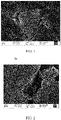
- FIG. 1 is a cross-sectional SEM image of a negative electrode plate according to an embodiment of this application.
- FIG. 2 is a magnified SEM image of FIG. 1 .
- pores 10 in silicon-based particles are pores inside the silicon-based particles
- pores 20 in a negative electrode plate are pores between various particles in a negative electrode material layer.
- An interface of the silicon-based particles was photographed by using a scanning transmission electron microscopy (STEM), and an obtained STEM image was used to measure porosity.
- STEM scanning transmission electron microscopy
- a specific process was as follows: Binarization processing was performed on an image threshold (threshold) of the STEM image by using Image J software. After a size was measured according to a scale, analyze particles (Analyze Particles) were used to measure an area of pores to obtain an area percentage, that is, porosity ⁇ 1 of the silicon-based particles. More than 20 silicon-based particles in an electrode plate were randomly selected for this same test, to obtain an average value.
- the silicon-based particles were sliced, and an element mass percentage average was measured by using EDS (energy dispersive X-ray spectroscopy) linear scanning.
- the gram capacity of the negative electrode material layer was tested by using a button battery.
- An assembled button battery was put under constant temperature of 25°C for 5 minutes, discharged to 0.005 V at 0.05C, left standing for 5 minutes, and discharged to 0.005 V at 20 ⁇ A. A sum of two discharge capacities was D0. After 5 minutes of standing, the assembled button battery was charged to 2.0 V at 0.1C, a charge capacity was C0 at that point, and first-cycle charging efficiency was C0/D0 ⁇ 100%.
- a punching machine was used to punch the negative electrode plate to obtain a small wafer with an area of S, mass of the small wafer was measured and recorded as M 1 , and a thickness of the small wafer was measured with a micrometer and recorded as H 1 .
- the same punching machine was used for punching to obtain a current collector with the same area S, mass of the current collector was measured and recorded as M 2 , and a thickness of the current collector was measured with the micrometer and recorded as H 2 .
- the compacted density of the negative electrode was (M 1 -M 2 )/(H 1 -H 2 )/S.
- sample powder was added to a 50 ml clean beaker, approximately 20 ml of deionized water was added, and a few drops of 1% surfactant were added so that the powder was fully dispersed in the water.
- Ultrasound processing was performed using a 120 W ultrasonic cleaning machine on the solution for 5 minutes, and particle size distribution was measured by using a laser diffraction particle size analyzer MasterSizer 2000.
- D v 50 was a diameter, where particles of this size and smaller than this size accounted for 50% in the volume-based distribution obtained using the laser diffraction particle size analyzer.
- the negative electrode active material obtained in the examples, conductive carbon black, and a binder PAA (modified polyacrylic acid) were added to deionized water at a mass ratio of 80:10:10, then stirred into a slurry, and applied with a scraper to form a coating with a thickness of 100 ⁇ m.
- the coating was dried in a vacuum drying oven at approximately 85°C for 12 hours, and then cut into a wafer with a diameter of 1 cm in a dry environment by using a punching machine.
- a lithium metal plate was used as a counter electrode, a Ceglar composite membrane was selected as a separator, and a liquid electrolyte was injected to obtain a button battery.
- a LAND (LAND) series battery test was performed on the battery, to measure charging and discharge capacities of the battery.
- the battery was discharged to 0.005 V at 0.05C, after 5 minutes of standing, the battery was discharged to 0.005 V at 50 ⁇ A, and after another 5 minutes of standing, the battery was discharged to 0.005 V at 10 ⁇ A to obtain a first-cycle lithium intercalation capacity of the material. Then, the battery was charged to 2 V at 0.1C to obtain a first-cycle lithium deintercalation capacity. Finally, a ratio of the first-cycle lithium deintercalation capacity to the first-cycle lithium intercalation capacity was the first-cycle efficiency of the material.
- Test temperature was 25/45°C, and the battery was charged to 4.4 V at a constant current of 0.7C, and charged to 0.025C at a constant voltage. After 5 minutes of standing, the battery was discharged to 3.0 V at 0.5C. A capacity obtained in this step was used as an initial capacity, and the battery was charged at 0.7C or discharged at 0.5C to perform a cycling test, and a ratio of a capacity obtained in each step to the initial capacity was calculated to obtain a capacity attenuation curve.
- the number of cycles when a capacity retention rate reached 90% after cycling at 25°C was recorded as room-temperature cycling performance of the lithium-ion battery, and the number of cycles when a capacity retention rate reached 80% after cycling at 45°C was recorded as high-temperature cycling performance of the lithium-ion battery.
- the numbers of cycles in the two cases were compared to obtain the cycling performance of the material.
- the battery was discharged to 3.0 V at 0.2C under 25°C, left standing for 5 minutes, charged to 4.45 V at 0.5C, charged to 0.05C at a constant voltage, and then left standing for 5 minutes.
- the discharging rate was adjusted, to perform discharging tests at 0.2C, 0.5C, 1C, 1.5C, and 2.0C respectively, to obtain discharge capacities respectively.
- a capacity obtained in each rate was compared with a capacity obtained at 0.2C, and the ratio at 2 C and the ratio at 0.2C were compared, to obtain rate performance.
- a thickness of a fresh lithium-ion battery in a half charged state was measured by using a spiral micrometer. After 400 cycles (cls), the lithium-ion battery was in a fully charged state. Then, a thickness of the lithium-ion battery was measured by using the spiral micrometer. The thickness was compared with the initial thickness of the fresh lithium-ion battery in the half charged state, to obtain a swelling rate of the fully-charged lithium-ion battery.
- a length, a width, and a height of the lithium-ion battery were measured by using a laser thickness gauge to obtain a volume (V) of the lithium-ion battery.
- a porous carbon material with porosity of 38% was placed in a sealed gas reactor containing silicon, and heated to 500°C, and the temperature was maintained for 4 hours. After cooling, screening, and degaussing, silicon-based particles whose porosity ⁇ 1 was 16% could be obtained. The percentage of carbon in the silicon-based particles was 60wt%, and the percentage B of silicon in the silicon-based particles was 40wt%.
- the foregoing prepared negative electrode active material, a graphite particle, and nano conductive carbon black were mixed at a mass ratio of 30:66.5:3.5 to obtain a first mixture.
- the first mixture and a binder PAA were added at a mass ratio of 95:5 to deionized water, to prepare a slurry containing 45% solid, and stirred uniformly to obtain a first mixed slurry.
- the first mixed slurry was evenly applied on a surface of copper foil serving as the negative electrode current collector with a thickness of 8 ⁇ m, and dried in the air drying oven for 2 minutes at 120°C, to obtain a negative electrode plate whose one surface was coated with a negative electrode active material, with a coating weight of 7.5 mg/cm 2 .
- a positive electrode active material lithium cobalt oxide (LiCoO 2 ), conductive carbon black (Super P), and polyvinylidene fluoride (PVDF) were mixed at a weight ratio of 97.5:1.0:1.5, and N-methylpyrrolidone (NMP) was added as a solvent to prepare a slurry containing 75% solid. The slurry was mixed evenly. The slurry was uniformly applied on a surface of aluminum foil serving as the positive electrode current collector with a thickness of 10 ⁇ m, and dried at 90°C, to obtain a positive electrode plate with a coating thickness of 110 ⁇ m. After the foregoing steps were completed, single-sided coating of the positive electrode plate was completed.
- LiCoO 2 lithium cobalt oxide
- Super P conductive carbon black
- PVDF polyvinylidene fluoride
- the foregoing steps were repeatedly performed on the other surface of the positive electrode plate to obtain a positive electrode plate whose both surfaces were coated with the positive electrode active material. After coating was completed, the electrode plate was cut into a size of 38 mm ⁇ 58 mm for use.
- Aluminum oxide and polyvinylidene fluoride were mixed at a mass ratio of 90:10 and dissolved in deionized water to form a ceramic slurry with 50% solid. Then, the ceramic slurry was uniformly applied on a face of a porous substrate (polyethylene with a thickness of 7 ⁇ m, an average pore diameter of 0.073 ⁇ m, and porosity of 26%) through the micro-gravure coating method, and dried to obtain a double-layer structure of a ceramic coating and the porous substrate. A thickness of the ceramic coating was 50 ⁇ m.
- PVDF Polyvinylidene fluoride
- polyacrylate was mixed at a mass ratio of 96:4 and dissolved in deionized water to form a polymer slurry with 50% solid. Then, the polymer slurry was uniformly applied on the two surfaces of the double-layer structure of the ceramic coating and the porous substrate through the micro-gravure coating method, and dried to obtain the separator. A thickness of a single-layer coating formed by the polymer slurry was 2 ⁇ m.
- the foregoing prepared positive electrode plate, the separator, and the negative electrode plate were sequentially stacked, the separator was sandwiched between the positive electrode and the negative electrode for separation, and the stack was wound to obtain an electrode assembly.
- the electrode assembly was placed in a packaging bag made of an aluminum-plastic film, and dried, and an electrolyte was injected.
- the lithium-ion battery was obtained through processes such as vacuum packaging, standing, formation, degassing, and trimming.
- Example 2 Example 3, Example 4, Example 5, Example 6, Example 7, Example 8, Example 9, Example 10, Example 11, Example 12, Example 13, Example 14, Example 15, Example 16, and Example 17 all have the same preparation steps as Example 1 for preparation of a negative electrode active material, preparation of a negative electrode plate, preparation of a positive electrode plate, preparation of a liquid electrolyte, preparation of a separator, and preparation of a lithium-ion battery, except for the changes of related preparation parameters shown in Table 1.
- Example 19 Example 20, Example 21, Example 22, Example 23, Example 24, Example 25, Example 26, Example 27, Example 28, Example 29, Example 30, Example 31, Example 32, and Example 33 have the same preparation steps as Example 18 for preparation of a negative electrode active material, preparation of a negative electrode plate, preparation of a positive electrode plate, preparation of a liquid electrolyte, preparation of a separator, and preparation of a lithium-ion battery, except for the changes of related preparation parameters shown in Table 2.
- Comparative Example 1 Comparative Example 2, Comparative Example 3, Comparative Example 4, Comparative Example 5, and Comparative Example 6 have the same preparation steps as Example 1 for preparation of a negative electrode active material, preparation of a negative electrode plate, preparation of a positive electrode plate, preparation of a liquid electrolyte, preparation of a separator, and preparation of a lithium-ion battery, except for the changes of related preparation parameters shown in Table 3.
- Table 3 Comparative example Porosity ⁇ 1 of silicon-based particle Porosity ⁇ 2 of negative electrode plate Percentage of carbon in silicon-based particle (wt%) Percentage B of silicon in silicon-based particle (wt%) 1 8% 15% 60 40 2 60% 15% 60 40 3 32% 10% 55 45 4 32% 62% 55 45 5 5% 28% 55 45 6 67% 28% 55 45
- Example 1 Preparation parameters of Example 1, Example 2, Example 3, Example 4, Example 5, Example 6, Example 7, Comparative Example 1, and Comparative Example 2 are shown in Table 4.
- Example 1 0.2 16% 40 3.6
- Example 2 0.4 25% 40 6.5
- Example 3 0.8 38% 40 10.3
- Example 5 1.6 56% 40 20.5
- Example 6 1.5 38% 20 13.3
- Example 7 0.5 38% 60 4.3 Comparative Example 1 0.1 8% 40 3.2 Comparative Example 2 1.9 60% 40 47.7
- Example 1 Example 2, Example 3, Example 4, Example 5, Example 6, Example 7, Comparative Example 1, and Comparative Example 2 are shown in Table 5.
- Table 5 Capacity retention rate after 400 cycles at 25°C Capacity retention rate after 200 cycles at 45°C Deformation rate after 400 cycles at 25°C Deformation rate after 200 cycles at 45°C Volumetric energy density (Wh/L)
- Example 1 83.6% 82.5% 10.3% 10.4% 786
- Example 2 88.9% 87.6% 8.2% 8.3% 792
- Example 3 92.4% 91.5% 6.3% 7.1% 816
- Example 4 91.3% 88.6% 6.3% 7.0% 782
- Example 5 90.3% 87.1% 6.2% 6.7% 770
- Example 6 93.3% 92.1% 6.0% 6.2% 752
- Example 7 87.7% 86.3% 9.6% 9.3% 806 Comparative Example 1 76.4% 74.6% 12.6% 11.8% 770 Comparative Example 2 81.3% 78.6% 11.3% 11.0% 750
- Example 8 Example 9, Example 10, Example 11, Example 12, Example 13, Example 14, Example 15, Example 16, Example 17, Comparative Example 3, Comparative Example 4, Comparative Example 5, and Comparative Example 6 are shown in Table 7.
- Table 7 Capacity retention rate after 400 cycles at 25°C Capacity retention rate after 200 cycles at 45°C Deformation rate after 400 cycles at 25°C Deformation rate after 200 cycles at 45°C Volumetric energy density (Wh/L)
- Example 8 85.1% 84.3% 10.1% 10.5% 799
- Example 9 87.6% 85.1% 8.7% 8.9% 798
- Example 10 91.6% 90.3% 6.7% 7.1% 816
- Example 11 90.5% 89.5% 6.8% 7.4% 795
- Example 16 90.5% 88.1% 6.9% 7.5% 777
- Example 2 Preparation parameters of Example 2, Example 18, Example 19, Example 20, Example 21, Example 22, Example 23, Example 24, Example 25, Example 26, Example 27, Example 28, Example 29, Example 30, Example 31, Example 32, and Example 33 are shown in Table 8.
- Table 8 Type of carbon material Percentage of carbon material
- Example 19 MCNT 0.10% CMC-Na 0.15%
- Example 21 SCNT 0.00% CMC-Na 0.15%
- Example 22 SCNT 0.01% CMC-Na 0.15%
- Example 23 SCNT 0.50% CMC-Na 0.15%
- Example 24 SCNT 1.00% CMC-Na 0.15%
- Example 25 SCNT 0.10% PVP 0.15%
- Example 26 SCNT 0.10% PVDF 0.15%
- Example 27 SCNT 0.10% PAANa 0.15%
- Example 28 SCNT 0.10% 0 0
- Example 29 SCNT 0.10% CMC-Na 0.4%
- Example 2 Example 18, Example 19, Example 20, Example 21, Example 22, Example 23, Example 24, Example 25, Example 26, Example 27, Example 28, Example 29, Example 30, Example 31, Example 32, and Example 33 are shown in Table 9.
- Table 9 Capacity retention rate after 400 cycles at 25°C Capacity retention rate after 200 cycles at 45°C Deformation rate after 400 cycles at 25°C Deformation rate after 200 cycles at 45°C Rate performance (2C)
- Example 2 91.4% 90.6% 6.7% 8.5% 87.7%
- Example 18 93.6% 91.3% 6.6% 8.0% 87.5%
- Example 19 92.1% 89.2% 6.9% 8.2% 87.6%
- Example 20 92.7% 90.2% 6.8% 8.5% 87.0%
- Example 21 90.5% 88.4% 6.7% 9.9% 84.8%
- Example 22 93.7% 91.5% 6.5% 8.4% 87.6%
- Example 23 93.8% 91.7% 6.9% 8,3% 88.1%
- Example 24 Unable to process
- Example 25 91.4% 88.5% 7.9% 9.
- Example 1 From Example 1, Example 2, Example 3, Example 4, Example 5, Comparative Example 1, and Comparative Example 2, it can be seen that when a percentage B of silicon was constant, a gram capacity of the negative electrode material layer did not significantly change. As the porosity ⁇ 1 of the silicon-based particles increased, the specific surface area of the silicon-based particles gradually increased. From Example 3, Example 6, and Example 7, it can be seen that a change in the percentage B of silicon in the silicon-based particles caused the change in the value of P, which affected the gram capacity of the negative electrode material layer and the specific surface area of the silicon-based particles.
- Example 1 From Example 1, Example 2, Example 3, Example 4, Example 5, Example 6, Example 7, Comparative Example 1, and Comparative Example 2, it can be seen that when P was excessively low, it was difficult for pores reserved inside the silicon-based particles to buffer volume swelling of nano-silicon during the lithium intercalation, it was difficult for a carbonaceous material with such mechanical strength to withstand enormous swelling stress, and as a result, a structure of the silicon-based particles broke down, exacerbating the electrochemical performance of the lithium-ion battery.
- Example 8 Example 9, Example 10, Example 11, Example 12, Comparative Example 3, and Comparative Example 4, it can be seen that when the porosity of the silicon-based particles was constant, and the porosity of the negative electrode plate was too low, the cycling performance and the swelling performance of the lithium-ion battery deteriorated significantly. This was because the pores inside the silicon-based particles could not completely alleviate volume swelling of silicon during lithium intercalation, and the porosity of the negative electrode plate was needed to further alleviate the swelling during the intercalation of lithium into silicon; and the volume swelling made it difficult for the liquid electrolyte to implement full infiltration, increasing the migration distance of the lithium ions and deteriorating the kinetic performance of lithium-ion batteries.
- the porosity of the negative electrode plate was too high, a gap between the particles in the negative electrode material layer was too large, and the contact area between the particles was reduced, which reduced intercalation sites for lithium ions; and the lithium-ion battery was prone to demoulding during the cycling, causing the cycling performance, the anti-swelling performance, and the kinetic performance of the lithium-ion battery to significantly deteriorate.
- the compacted density of the negative electrode plate was reduced, and the volumetric energy density of the lithium-ion battery was also significantly reduced.
- Example 13 Example 14, Example 15, Example 16, Example 17, Comparative Example 7, and Comparative Example 8, it can be seen that when the porosity of the negative electrode plate was constant, and the porosity of the silicon-based particles was too low, the cycling performance and the swelling performance of the lithium-ion battery significantly deteriorated. This was because the space reserved inside the silicon-based particles could not buffer the volume swelling of nano-silicon during the lithium intercalation. In this case, the mechanical strength of the carbonaceous material could not withstand the huge swelling stress, causing the structure of the silicon-based particles to crack during cycling.
- the porosity of the silicon-based particles was too high, the compressive strength of the carbonaceous material was reduced, and as a result, the silicon-based particles were prone to breakdown during processing, deteriorating the electrical performance; and as the compacted density of the electrode plate decreased, the volumetric energy density of the lithium-ion battery was also reduced.
- Example 9 Example 10, Example 11, Example 12, Example 13, Example 14, Example 15, Example 16, and Example 17, it can be seen that the porosity of the negative electrode plate and the porosity of the silicon-based particles in the lithium-ion battery were appropriately arranged, which could more effectively improve the cycling performance and the anti-swelling performance of the lithium-ion battery, and improve the volumetric energy density of the lithium-ion battery.
- Example 18 From comparison between Example 18, Example 19, Example 20, Example 21, Example 22, Example 23, Example 24, Example 25, Example 26, Example 27, Example 28, Example 29, Example 30, Example 31, Example 32, Example 33, and Example 2, it can be seen that adding 0.1wt% SCNT to the surfaces of the silicon-based particles could significantly improve the cycling performance, adding 0.1wt% MCNT could slightly improve the cycling performance, and adding 0.05wt% SCNT and 0.05wt% MCNT could improve the cycling performance to some extent.
- Example 18, Example 21, Example 22, Example 23, and Example 24 the amount of SCNT added was changed. Controlling the amount of SCNT added to be equal to or less than 0.5% could effectively improve the cycling performance.
- Example 18 Example 28, Example 29, and Example 30, the amount of dispersant added was changed.
- the amount of dispersant was 0.4wt%, a dispersion effect was improved, but too many dispersants would exacerbate the rate performance.
- the amount of dispersant was 0.025wt%, the dispersing effect was poor, and the cycling performance and the rate performance deteriorated compared with those when the amount of dispersant was 0.15wt%.
- Coatings of different carbon materials in Example 28, Example 31, Example 32, and Example 33 were compared. From the results, it can be seen that the coating effect of CNT and graphene was optimal. This was because the coatings of CNT and graphene not only increased the electronic conductivity of the material, but also increased the contact points between the materials, thereby alleviating the cycling attenuation caused by a contact failure.
- the negative electrode plate provided in this application could significantly improve the cycling performance and reduce swelling and deformation for the electrochemical apparatus.
Landscapes
- Chemical & Material Sciences (AREA)
- Chemical Kinetics & Catalysis (AREA)
- Electrochemistry (AREA)
- General Chemical & Material Sciences (AREA)
- Engineering & Computer Science (AREA)
- Materials Engineering (AREA)
- Composite Materials (AREA)
- Inorganic Chemistry (AREA)
- Manufacturing & Machinery (AREA)
- Battery Electrode And Active Subsutance (AREA)
- Secondary Cells (AREA)
- Electric Double-Layer Capacitors Or The Like (AREA)
Abstract
Description
- This application relates to the electrochemical field, and specifically, to a negative electrode plate, and an electrochemical apparatus and electronic apparatus including such negative electrode plate.
- Lithium-ion secondary batteries have advantages such as high energy storage density, high open-circuit voltage, low self-discharge rate, long cycle life, and good safety, and therefore are widely applied to various fields such as electric energy storage, mobile electronic devices, electric vehicles, and aviation equipment. With rapid development of the mobile electronic devices and the electric vehicles, requirements for energy density, safety, cycling performance, service life, and the like of the lithium-ion secondary batteries are getting increasingly high in the market.
- With a theoretical capacity of up to 4200 mAh/g, silicon-based materials are currently known as negative electrode materials with the highest theoretical capacity. In addition, silicon is abundant and cost effective. Therefore, at present, the silicon-based materials are often used as next-generation negative electrode materials with a high gram capacity for negative electrode plates in lithium-ion secondary batteries. However, the silicon-based materials have a volume change rate of up to 300% during lithium intercalation/deintercalation. As a result, the negative electrode materials are likely to crack and fall off, thereby affecting the electrochemical performance of the lithium-ion secondary batteries.
- This application is intended to provide a negative electrode plate, and an electrochemical apparatus and electronic apparatus including such negative electrode plate, to improve electrochemical performance of the electrochemical apparatus.
- It should be noted that an example in which a lithium-ion battery is used as an electrochemical apparatus is used to illustrate this application below. However, the electrochemical apparatus in this application is not limited to the lithium-ion battery.
- Specific technical solutions are as follows:
A first aspect of this application provides a negative electrode plate, including a negative electrode material layer, where the negative electrode material layer includes silicon-based particles and graphite particles, and the silicon-based particles include silicon and carbon; and porosity α1 of the silicon-based particles and a percentage B of silicon in the silicon-based particles satisfy P=0.5α1/(B-α1B), where 0.2≤P≤1.6; where the porosity α1 of the silicon-based particles is 15% to 60%, and the percentage B of silicon in the silicon-based particles is 20wt% to 60wt%. - In this application, "the porosity α1 of the silicon-based particles" refers to a percentage of a volume of pores in the silicon-based particles in a total volume of the silicon-based particles.
- In an embodiment of this application, porosity α2 of the negative electrode plate and the percentage B of silicon satisfy P=0.5α1/(B-α1B), where 0.2≤P≤1.6. For example, a lower limit of P may include the following value: 0.2, 0.4, 0.5, or 0.8; and an upper limit of P may include the following value: 1.1, 1.5, or 1.6. When P is less than 0.2, it is difficult for pores reserved in the silicon-based particles to buffer volume swelling of nano-silicon during the lithium intercalation, it is difficult for a carbonaceous material with such mechanical strength to withstand enormous swelling stress, and as a result, a structure of the silicon-based particles breaks down, exacerbating the electrochemical performance. When P is greater than 1.6, pores reserved in the silicon-based particles are too large, and as a result, mechanical compressive strength of the carbonaceous material deteriorates, the silicon-based particles are prone to breakdown during processing, and a large number of fresh interfaces are exposed, reducing first-cycle efficiency, cycling performance, and energy density of the lithium-ion battery. Therefore, controlling P within the foregoing range can effectively improve the energy density, cycling performance, and anti-swelling performance of the lithium-ion battery.
- In this application, the porosity α1 of the silicon-based particles is 15% to 60%. For example, a lower limit of the porosity α1 of the silicon-based particles may include the following value: 15%, 16%, 18%, 25%, 32%, or 34%; and an upper limit of the porosity α1 of the silicon-based particles may include the following value: 38%, 43%, 45%, 47%, 56%, or 60%. When the porosity α1 of the silicon-based particles is less than 15%, it is difficult for reserved space to buffer volume swelling of nano-silicon during the lithium intercalation, it is difficult for a carbonaceous material with such mechanical strength to withstand enormous swelling stress, and as a result, a structure of the silicon-based particles breaks down, exacerbating the electrochemical performance. When the porosity α1 of the silicon-based particles is greater than 60%, pores are too large, and as a result, compressive strength of the carbonaceous material deteriorates, and the silicon-based particles are prone to breakdown during processing, exacerbating the electrochemical performance.
- In this application, the percentage B of silicon in the silicon-based particles is 20wt% to 60wt%. For example, a lower limit of the percentage B of silicon may include the following value: 20wt% or 40wt%; and an upper limit of the percentage B of silicon may include the following value: 45wt% or 60wt%. When the percentage B of silicon is less than 20wt%, the negative electrode material layer has a small gram capacity; or when the percentage B of silicon is greater than 60wt%, a volume change rate of the silicon-based particles in the process of lithium intercalation/deintercalation is increased, thereby generating more SEI and accelerating consumption of lithium ions and a liquid electrolyte in the lithium-ion battery, which significantly increases impedance of the lithium-ion battery.
- In this application, the silicon-based particles may include silicon and carbon, and the silicon-based particles may further include oxygen, nitrogen, phosphorus, sulfur, and the like. This application imposes no particular limitation on the type of the silicon-based particles, provided that the purpose of this application can be achieved. For example, the silicon-based particles may include at least one of nano-silicon, silicon nano-silicon, silicon carbide, nano silicon oxide, or silicon-metal alloy.
- In general, the negative electrode plate provided in this application includes the negative electrode material layer, and the negative electrode material layer includes the silicon-based particles and the graphite particles. Pores are created inside the silicon-based particles, so that the porosity α1 of the silicon-based particles and the percentage B of silicon in the silicon-based particles satisfy P=0.5α1/(B-α1B), where 0.2≤P≤1.6, which can effectively alleviate swelling of the silicon-based particles during the lithium intercalation, thereby improving the cycling performance and reducing swelling and deformation of the lithium-ion battery.
- In an embodiment of this application, porosity α2 of the negative electrode plate is 15% to 41%. For example, a lower limit of the porosity α2 of the negative electrode plate may include the following value: 15%, 19%, or 28%; and an upper limit of the porosity α2 of the negative electrode plate may include the following value: 28%, 29%, 35%, or 41%. When the porosity α2 of the negative electrode plate is less than 15%, it is difficult for the liquid electrolyte to implement full infiltration, and as a result, a migration distance of lithium ions is increased, exacerbating kinetic performance of the lithium-ion battery. When the porosity α2 of the negative electrode plate is greater than 41%, contact between the silicon-based particles and the graphite particles is prone to failure during cycling of the lithium-ion battery, reducing cycling performance and energy density of the lithium-ion battery.
- In this application, the "porosity α2 of the negative electrode plate" refers to a percentage of a volume of pores between various particles in the negative electrode plate in a total volume of the negative electrode plate.
- In this application, the pores in the silicon-based particles and the pores in the negative electrode plate separately include micropores with a pore diameter less than 2 nm, mesopores with a pore diameter of 2 nm to 50 nm, or macropores with a pore diameter greater than 50 nm. Numbers of micropores, mesopores, and macropores in this application are not particularly limited, provided that the purpose of this application can be achieved.
- In an embodiment of this application, a sum α of the porosity α1 of the silicon-based particles and the porosity α2 of the negative electrode plate satisfies 45%<α<90%. For example, a lower limit of the sum α of the porosity α1 of the silicon-based particles and the porosity α2 of the negative electrode plate may include the following value: 43%, 46%, 47%, 51%, 53%, 60%, 62%, or 67%; and an upper limit of the sum α of the porosity α1 of the silicon-based particles and the porosity α2 of the negative electrode plate may include the following value: 71%, 72%, 73%, 88%, or 89%. When the sum α of the porosity α2 of the negative electrode plate and the porosity α1 of the silicon-based particles is controlled within the foregoing range, the cycling performance and the anti-swelling performance of the lithium-ion battery are significantly improved.
- In an embodiment of this application, a percentage of silicon-based particles in the negative electrode material layer is 3wt% to 80wt%. For example, a lower limit of the percentage of silicon-based particles in the negative electrode material layer may include the following value: 3wt%, 10wt%, 20wt%, 25wt%, 30wt%, 35wt%, or 40wt%; and an upper limit of the percentage of silicon-based particles in the negative electrode material layer may include the following value: 45wt%, 55wt%, 60wt%, 70wt%, or 80wt%. The percentage of silicon-based particles in the negative electrode material layer is controlled within the foregoing range, so that the negative electrode material layer has a high gram capacity, thereby increasing the energy density of the lithium-ion battery.
- In this application, the percentage of the graphite particles in the negative electrode material layer is not particularly limited, provided that the purpose of this application can be achieved. For example, the percentage of the graphite particles in the negative electrode material layer may be 20wt% to 97wt%. A lower limit of the percentage of the graphite particles in the negative electrode material layer may include the following value: 20wt%, 25wt%, 30wt%, or 40wt%, and an upper limit of the percentage of the graphite particles in the negative electrode material layer may include the following value: 50wt%, 60wt%, 70wt%, 80wt%, or 90wt%. The percentage of the graphite particles in the negative electrode material layer is controlled within the foregoing range, so that conductivity of the negative electrode material layer is enhanced, reducing contact between the negative electrode material layer and the liquid electrolyte and reducing generation of the SEI.
- In an embodiment of this application, a peak intensity ratio of a peak D to a peak G in the Raman test of the silicon-based particles is 0.2 to 3; and the peak D is a peak whose shift range is 1255 cm-1 to 1355 cm-1 in a Raman spectrum of the silicon-based particles, and the peak G is a peak whose shift range is 1575 cm-1 to 1600 cm-1 in the Raman spectrum of the silicon-based particles. When the peak intensity ratio of the peak D to the peak G in the Raman test of the silicon-based particles is controlled within the foregoing range, the carbonaceous material of the silicon-based particles has sufficient pore defects, to help inhibit swelling and deformation of the carbonaceous material during cycling, thereby improving the anti-swelling performance and cycling performance of the negative electrode plate.
- In an embodiment of this application, there is a carbon material on the surfaces of the silicon-based particles. This application imposes no specific limitation on the type of the carbon material, provided that the purpose of this application can be achieved. For example, the carbon material may include at least one of amorphous carbon, carbon nanotube, carbon nanoparticle, vapor-deposited carbon fiber, graphene, or the like. In some embodiments of this application, the carbon nanotube may include at least one of a single-walled carbon nanotube or a multi-walled carbon nanotube. This application imposes no particular limitation on a method for preparing the carbon material on the surfaces of the silicon-based particles, provided that the purpose of this application can be achieved. In this application, the percentage of the carbon material is not particularly limited, provided that the purpose of this application can be achieved. For example, the percentage of the carbon material may be 0.01wt% to 1wt% of the silicon-based particles, for example, 0.01wt%, 0.1wt%, 0.5wt%, or 1wt%. Providing the carbon material on the surfaces of the silicon-based particles helps improve interface stability of the surfaces of the silicon-based particles to constrain shift of the silicon-based particles and also effectively alleviate a structural damage caused by volume swelling and shrinkage of the silicon-based particles, avoiding generation of fresh interfaces, improving the cycling performance, and reducing the swelling and the deformation for the negative electrode plate.
- In an embodiment of this application, there is a polymer material on the surfaces of the silicon-based particles. This application imposes no particular limitation on the type of the polymer material, provided that the purpose of this application can be achieved. For example, the polymer material may include at least one of polyvinylidene fluoride (PVDF), carboxymethyl cellulose (CMC), sodium carboxymethyl cellulose (CMC-Na), polyvinylpyrrolidone (PVP), polyacrylic acid, poly styrene butadiene rubber, derivative thereof, or the like. In some embodiments of this application, the polymer material may include sodium carboxymethyl cellulose, polyvinylpyrrolidone, polyvinylidene fluoride, and polyacrylic acid sodium (PAANa). This application imposes no particular limitation on a method for preparing the polymer material on the surfaces of the silicon-based particles, provided that the purpose of this application can be achieved. In this application, the percentage of the polymer material is not particularly limited, provided that the purpose of this application can be achieved. The percentage of the polymer material may be 0wt% to 0.4wt% of the silicon-based particles, for example, 0wt%, 0.025wt%, 0.15wt%, or 0.4wt%.
- In an embodiment of this application, a median particle size Dv50 of the silicon-based particles is less than 20 µm. When the median particle size Dv50 of the silicon-based particles is greater than 20 µm, there may be problems such as scratches during the processing of the negative electrode plate, and mutual contact points between the particles are reduced, thereby affecting the cycling performance of the negative electrode plate. Controlling the median particle size Dv50 of the silicon-based particles in this application within the foregoing range can improve the cycling performance of the negative electrode plate. The particle size of the graphite particles in this application is not particularly limited, provided that the purpose of this application can be achieved.
- In an embodiment of this application, a specific surface area of the silicon-based particles is less than 50 m2/g. When the specific surface area of the silicon-based particles is greater than 50m2/g, the specific surface area of the silicon-based particle is too large, side reactions affect the performance of the lithium-ion battery, and a higher proportion of binder needs to be consumed, causing a decrease in adhesion between the negative electrode material layer and a negative electrode current collector and a higher growth rate of internal resistance. A value of the specific surface area of the graphite particles in this application is not particularly limited, provided that the purpose of this application can be achieved.
- Compacted density of the negative electrode plate in this application is 1.0 g/cm3 to 1.9 g/cm3, so that the lithium-ion battery can have high energy density.
- In this application, the negative electrode current collector in the negative electrode plate is not particularly limited, provided that the purpose of this application can be achieved. For example, the negative electrode current collector may include copper foil, copper alloy foil, nickel foil, stainless steel foil, titanium foil, nickel foam, copper foam, a composite current collector, or the like. In this application, thicknesses of the negative electrode current collector and the negative electrode material layer are not particularly limited, provided that the purpose of this application can be achieved. For example, the thickness of the negative electrode current collector is 6 µm to 10 µm, and the thickness of the negative electrode material layer is 30 µm to 120 µm. The thickness of the negative electrode plate in this application is not particularly limited, provided that the purpose of this application can be achieved. For example, the thickness of the negative electrode plate is 50 µm to 150 µm.
- Optionally, the negative electrode plate may further include a conductive layer, and the conductive layer is located between the negative electrode current collector and the negative electrode material layer. Composition of the conductive layer is not particularly limited, and the conductive layer may be a conductive layer commonly used in the art. The conductive layer includes a conductive agent and a binder.
- A positive electrode plate in this application is not particularly limited, provided that the purpose of this application can be achieved. For example, the positive electrode plate usually includes a positive electrode current collector and a positive electrode material layer. The positive electrode current collector is not particularly limited, provided that the purpose of this application can be achieved. For example, the positive electrode current collector may include aluminum foil, aluminum alloy foil, a composite current collector, or the like. The positive electrode material layer includes a positive electrode active material, and the positive electrode active material is not particularly limited, provided that the purpose of this application can be achieved. For example, the positive electrode active material may include at least one of lithium nickel cobalt manganate (811, 622, 523, and 111), lithium nickel cobalt aluminate, lithium iron phosphate, lithium-rich manganese-based material, lithium cobalt oxide, lithium manganate oxide, lithium manganese iron phosphate, or lithium titanate. Thicknesses of the positive electrode current collector and the positive electrode material layer in this application are not particularly limited, provided that the purpose of this application can be achieved. For example, the thickness of the positive electrode current collector is 8 µm to 12 µm, and the thickness of the positive electrode material layer is 30 µm to 120 µm.
- Optionally, the positive electrode plate may further include a conductive layer, and the conductive layer is located between the positive electrode current collector and the positive electrode material layer. Composition of the conductive layer is not particularly limited, and the conductive layer may be a conductive layer commonly used in the art. The conductive layer includes a conductive agent and a binder.
- The conductive agent is not particularly limited, provided that the purpose of this application can be achieved. For example, the conductive agent may include at least one of conductive carbon black (Super P), carbon nanotubes (CNTs), carbon fiber, flake graphite, Ketjen black, graphene, or the like. The binder is not particularly limited, and any binder known in the art can be used provided that the purpose of this application can be achieved. For example, the binder may include at least one of poly propylene glycol, sodium polyacrylate, potassium polyacrylate, lithium polyacrylate, polyimide, polyimide, polyamide-imide, styrene butadiene rubber (SBR), polyvinyl alcohol (PVA), polyvinylidene fluoride, polytetrafluoroethylene ethylene (PTFE), carboxymethyl cellulose, sodium carboxymethyl cellulose (CMC-Na), or the like. For example, styrene butadiene rubber (SBR) may be selected as the binder.
- The separator in this application is not particularly limited, provided that the purpose of this application can be achieved. For example, the separator is at least one of a polyethylene (PE) or polypropylene (PP)-dominant polyolefin (PO) separator, a polyester film (for example, a polyethylene terephthalate (PET) film), a cellulose film, a polyimide (PI) film, a polyamide (PA) film, a spandex or aramid film, a woven film, a non-woven film (non-woven fabric), a microporous film, a composite film, separator paper, a laminated film, a spun film, or the like.
- For example, the separator may include a substrate layer and a surface treatment layer. The substrate layer may be a non-woven fabric, membrane, or composite membrane having a porous structure, and a material of the substrate layer may include at least one of polyethylene, polypropylene, polyethylene terephthalate, polyimide, or the like. Optionally, a polypropylene porous membrane, a polyethylene porous membrane, polypropylene nonwoven fabric, polyethylene nonwoven fabric, or a polypropylene-polyethylene-polypropylene porous composite membrane can be used. Optionally, the surface treatment layer is provided on at least one surface of the substrate layer, and the surface treatment layer may be a polymer layer or an inorganic layer, or may be a layer including both a polymer and an inorganic substance.
- For example, the inorganic layer includes inorganic particles and a binder. The inorganic particles are not particularly limited, and may be selected from, for example, at least one of aluminum oxide, silicon oxide, magnesium oxide, titanium oxide, hafnium oxide, tin oxide, ceria oxide, nickel oxide, zinc oxide, calcium oxide, zirconium oxide, yttrium oxide, silicon carbide, boehmite, aluminum hydroxide, magnesium hydroxide, calcium hydroxide, barium sulfate, or the like. The binder is not particularly limited, and may be selected from, for example, a combination of one or more of polyvinylidene fluoride, vinylidene fluoride-hexafluoropropylene copolymer, polyamide, polyacrylonitrile, polyacrylate, polyacrylic acid, polyacrylate,polyvinylpyrrolidone, polyvinyl ether, polymethyl methacrylate, polytetrafluoroethylene, and polyhexafluoropropylene. The polymer layer includes a polymer, and a material of the polymer includes at least one of polyamide, polyacrylonitrile, acrylate polymer, polyacrylic acid, polyacrylate, polyvinylpyrrolidone, polyvinyl ether, polyvinylidene fluoride, poly(vinylidene fluoride-hexafluoropropylene), or the like. The lithium-ion battery in this application further includes the electrolyte. The electrolyte may be one or more of a gel electrolyte, a solid electrolyte, and a liquid electrolyte, and the liquid electrolyte includes a lithium salt and a non-aqueous solvent.
- In some embodiments of this application, the lithium salt may include at least one of LiPF6, LiBF4, LiAsF6, LiClO4, LiB(C6H5)4, LiCH3SO3, LiCF3SO3, LiN(SO2CF3)2, LiC(SO2CF3)3, LiSiF6, LiBOB, or lithium difluoro oxalate borate. For example, LiPF6 may be selected as the lithium salt because LiPF6 can provide high ionic conductivity and improve cycling performance.
- The non-aqueous solvent is a carbonate compound, a carboxylate compound, an ether compound, another organic solvent, or a combination thereof. The carbonate compound may be a linear carbonate compound, a cyclic carbonate compound, a fluorocarbonate compound, or a combination thereof. An instance of the linear carbonate compound is dimethyl carbonate (DMC), diethyl carbonate (DEC), dipropyl carbonate (DPC), methyl propyl carbonate (MPC), ethylene propyl carbonate (EPC), methyl ethyl carbonate (MEC), or a combination thereof. An instance of the cyclic carbonate compound is ethylene carbonate (EC), propylene carbonate (PC), butylene carbonate (BC), vinyl ethylene carbonate (VEC), and a combination thereof. An instance of the fluorocarbonate compound is fluoroethylene carbonate (FEC), 1,2-difluoroethylene carbonate, 1,1-difluoroethylene carbonate, 1,1,2-trifluoroethylene carbonate, 1,1,2,2-tetrafluoroethylene carbonate, 1-fluoro-2-methylethylene carbonate, 1-fluoro-1-methylethylene carbonate, 1,2-difluoro-1-methylethylene carbonate, 1,1,2-trifluoro-2-methylethylene carbonate, trifluoromethylethylene carbonate, and a combination thereof. An instance of the carboxylate compound is methyl formate, methyl acetate, ethyl acetate, n-propyl acetate, tert-butyl acetate, methyl propionate, ethyl propionate, propyl propionate, γ-butyrolactone, decanolide, valerolactone, mevalonolactone, caprolactone, and a combination thereof. An instance of the ether compound is dibutyl ether, tetraglyme, diglyme, 1,2-dimethoxyethane, 1,2-diethoxyethane, ethoxymethoxy ethane, 2-methyltetrahydrofuran, tetrahydrofuran, and a combination thereof. An instance of the another organic solvent is dimethyl sulfoxide, 1,2-dioxolane, sulfolane, methyl-sulfolane, 1,3-dimethyl-2-imidazolidinone, N-methyl-2-pyrrolidone, formamide, dimethylformamide, acetonitrile, trimethyl phosphate, triethyl phosphate, trioctyl phosphate, phosphate ester, and a combination thereof.
- This application further provides an electrochemical apparatus, including a negative electrode plate, where the negative electrode plate is the negative electrode plate according to any one of the foregoing embodiments, and the electrochemical apparatus has good cycling performance, anti-swelling performance, rate performance, and volumetric energy density.
- The electrochemical apparatus in this application is not particularly limited, and may include any apparatus in which an electrochemical reaction occurs. In some embodiments, the electrochemical apparatus may include, but is not limited to a lithium metal secondary battery, a lithium-ion secondary battery (lithium-ion battery), a lithium polymer secondary battery, a lithium-ion polymer secondary battery, or the like.
- This application further provides an electronic apparatus, including the electrochemical apparatus according to the embodiments of this application, and the electronic apparatus has good cycling performance, anti-swelling performance, rate performance, and volumetric energy density.
- The electronic apparatus in this application is not particularly limited, and the electronic apparatus may be any known electronic apparatus in the prior art. In some embodiments, the electronic apparatus may include but not limited to a notebook computer, a pen-input computer, a mobile computer, an electronic book player, a portable telephone, a portable fax machine, a portable copier, a portable printer, a headset, a video recorder, a liquid crystal television, a portable cleaner, a portable CD player, a mini-disc, a transceiver, an electronic notebook, a calculator, a storage card, a portable recorder, a radio, a standby power source, a motor, an automobile, a motorcycle, a motor bicycle, a bicycle, a lighting appliance, a toy, a game console, a clock, an electric tool, a flash lamp, a camera, a large household battery, a lithium-ion capacitor, and the like.
- A process for preparing the electrochemical apparatus is well known to a person skilled in the art, and is not particularly limited in this application. For example, the electrochemical apparatus can be manufactured through the following process: A positive electrode plate and a negative electrode plate are stacked with a separator inbetween, and are put into a housing after undergoing operations such as winding and folding as needed, a liquid electrolyte is injected into the housing, and the housing is sealed. The separator used is the foregoing separator provided in this application. In addition, an overcurrent protection element, a guide plate, and the like may be provided in the housing as needed, to prevent internal pressure increase, overcharge, and over-discharge of the electrochemical apparatus.
- Based on the negative electrode plate and the electrochemical apparatus and the electronic apparatus including such negative electrode plate provided in this application, the negative electrode material layer of the negative electrode plate includes the silicon-based particles and the graphite particles, and the pores are created inside the silicon-based particles, so that the porosity α1 of the silicon-based particles and the percentage B of silicon in the silicon-based particles satisfy P=0.5α1/(B-α1B), where 0.2≤P≤1.6, which can effectively alleviate swelling of the silicon-based particles during the lithium intercalation, thereby improving the cycling performance and reducing swelling and deformation for the electrochemical apparatus.
- To describe the technical solutions in this application and the prior art more clearly, the following briefly describes the accompanying drawings required for describing the embodiments and the prior art. Apparently, the accompanying drawings in the following description show merely some embodiments of this application.
-
FIG. 1 is a cross-sectional SEM (scanning electron microscope) image of a negative electrode plate according to an embodiment of this application; and -
FIG. 2 is a magnified SEM image ofFIG. 1 . - Reference signs: 10. Pores in silicon-based particles; and 20. Pores in a negative electrode plate.
- To make the objectives, technical solutions, and advantages of this application more comprehensible, the following describes this application in detail with reference to accompanying drawings and embodiments. Apparently, the described embodiments are merely some but not all of the embodiments of this application. All other technical solutions obtained by a person of ordinary skill in the art based on the embodiments of this application fall within the protection scope of this application.
- It should be noted that, in the specific embodiments of this application, an example in which a lithium-ion battery is used as an electrochemical apparatus is used to illustrate this application. However, the electrochemical apparatus in this application is not limited to the lithium-ion battery.
-
FIG. 1 is a cross-sectional SEM image of a negative electrode plate according to an embodiment of this application.FIG. 2 is a magnified SEM image ofFIG. 1 . Referring toFIG. 2 , pores 10 in silicon-based particles are pores inside the silicon-based particles, and pores 20 in a negative electrode plate are pores between various particles in a negative electrode material layer. - The following uses examples and comparative examples to describe the embodiments of this application more specifically. Various tests and evaluations were performed in the following methods. In addition, unless otherwise specified, "part" and "%" are based on mass.
- An interface of the silicon-based particles was photographed by using a scanning transmission electron microscopy (STEM), and an obtained STEM image was used to measure porosity. A specific process was as follows: Binarization processing was performed on an image threshold (threshold) of the STEM image by using Image J software. After a size was measured according to a scale, analyze particles (Analyze Particles) were used to measure an area of pores to obtain an area percentage, that is, porosity α1 of the silicon-based particles. More than 20 silicon-based particles in an electrode plate were randomly selected for this same test, to obtain an average value.
- The silicon-based particles were sliced, and an element mass percentage average was measured by using EDS (energy dispersive X-ray spectroscopy) linear scanning.
- A same die was used for punching to obtain 50 negative electrode plates with a radius of d, a thickness h of each electrode plate was measured by using a micrometer, and the negative electrode plates were loaded into a sample chamber of an AccuPyc 1340 instrument. Helium (He) was used to fill the electrode plates in the sealed sample chamber, and then true volumes V of the electrode plates were obtained by using Bohr's law: PV=nRT. After the test was completed, the number of small wafers was counted, and apparent volumes of the samples were calculated as follows: πd2×50×h. Finally, porosity α2 of the negative electrode plates was obtained by the following equation: α2=1-V/πd2×50×h.
- At low constant temperature (-199°C to -193°C), after amounts of gas adsorbed on a solid surface under different relative pressure were measured, an adsorption capacity of a sample monolayer was obtained based on the Brunauer-Emmett-Teller adsorption theory and a equation thereof (BET equation), to calculate a specific surface area of the solid.
- BET equation:

- W: Mass of gas adsorbed by the solid sample under relative pressure (P/P0), measured in cm3/g;
- Wm: Saturated adsorption amount of gas covering an entire monolayer, measured in cm3/g;
- C: Constant related to heat of adsorption and condensation of a first layer;
- Slope: (c - 1)/(WmC); intercept: 1/WmC; total specific surface area: (Wm×N×Acs/M); and
- Specific surface area: S=St/m, where m is mass of the sample; and Acs: an average area 16.2 A2 occupied per N2 molecule.
- 1.5 g to 3.5 g of sample powder was weighed and put into a test sample tube of TriStar II 3020, and was degassed at 200°C for 120 minutes before testing.
- The gram capacity of the negative electrode material layer was tested by using a button battery. An assembled button battery was put under constant temperature of 25°C for 5 minutes, discharged to 0.005 V at 0.05C, left standing for 5 minutes, and discharged to 0.005 V at 20 µA. A sum of two discharge capacities was D0. After 5 minutes of standing, the assembled button battery was charged to 2.0 V at 0.1C, a charge capacity was C0 at that point, and first-cycle charging efficiency was C0/D0×100%.
- A punching machine was used to punch the negative electrode plate to obtain a small wafer with an area of S, mass of the small wafer was measured and recorded as M1, and a thickness of the small wafer was measured with a micrometer and recorded as H1. The same punching machine was used for punching to obtain a current collector with the same area S, mass of the current collector was measured and recorded as M2, and a thickness of the current collector was measured with the micrometer and recorded as H2. The compacted density of the negative electrode was (M1-M2)/(H1-H2)/S.
- Approximately 0.02 g of sample powder was added to a 50 ml clean beaker, approximately 20 ml of deionized water was added, and a few drops of 1% surfactant were added so that the powder was fully dispersed in the water. Ultrasound processing was performed using a 120 W ultrasonic cleaning machine on the solution for 5 minutes, and particle size distribution was measured by using a laser diffraction particle size analyzer MasterSizer 2000.
- Dv50 was a diameter, where particles of this size and smaller than this size accounted for 50% in the volume-based distribution obtained using the laser diffraction particle size analyzer.
- The negative electrode active material obtained in the examples, conductive carbon black, and a binder PAA (modified polyacrylic acid) were added to deionized water at a mass ratio of 80:10:10, then stirred into a slurry, and applied with a scraper to form a coating with a thickness of 100 µm. The coating was dried in a vacuum drying oven at approximately 85°C for 12 hours, and then cut into a wafer with a diameter of 1 cm in a dry environment by using a punching machine. In a glove box, a lithium metal plate was used as a counter electrode, a Ceglar composite membrane was selected as a separator, and a liquid electrolyte was injected to obtain a button battery. For a charging and discharging test, a LAND (LAND) series battery test was performed on the battery, to measure charging and discharge capacities of the battery.
- First, the battery was discharged to 0.005 V at 0.05C, after 5 minutes of standing, the battery was discharged to 0.005 V at 50 µA, and after another 5 minutes of standing, the battery was discharged to 0.005 V at 10 µA to obtain a first-cycle lithium intercalation capacity of the material. Then, the battery was charged to 2 V at 0.1C to obtain a first-cycle lithium deintercalation capacity. Finally, a ratio of the first-cycle lithium deintercalation capacity to the first-cycle lithium intercalation capacity was the first-cycle efficiency of the material.
- Test temperature was 25/45°C, and the battery was charged to 4.4 V at a constant current of 0.7C, and charged to 0.025C at a constant voltage. After 5 minutes of standing, the battery was discharged to 3.0 V at 0.5C. A capacity obtained in this step was used as an initial capacity, and the battery was charged at 0.7C or discharged at 0.5C to perform a cycling test, and a ratio of a capacity obtained in each step to the initial capacity was calculated to obtain a capacity attenuation curve. The number of cycles when a capacity retention rate reached 90% after cycling at 25°C was recorded as room-temperature cycling performance of the lithium-ion battery, and the number of cycles when a capacity retention rate reached 80% after cycling at 45°C was recorded as high-temperature cycling performance of the lithium-ion battery. The numbers of cycles in the two cases were compared to obtain the cycling performance of the material.
- The battery was discharged to 3.0 V at 0.2C under 25°C, left standing for 5 minutes, charged to 4.45 V at 0.5C, charged to 0.05C at a constant voltage, and then left standing for 5 minutes. The discharging rate was adjusted, to perform discharging tests at 0.2C, 0.5C, 1C, 1.5C, and 2.0C respectively, to obtain discharge capacities respectively. A capacity obtained in each rate was compared with a capacity obtained at 0.2C, and the ratio at 2 C and the ratio at 0.2C were compared, to obtain rate performance.
- A thickness of a fresh lithium-ion battery in a half charged state was measured by using a spiral micrometer. After 400 cycles (cls), the lithium-ion battery was in a fully charged state. Then, a thickness of the lithium-ion battery was measured by using the spiral micrometer. The thickness was compared with the initial thickness of the fresh lithium-ion battery in the half charged state, to obtain a swelling rate of the fully-charged lithium-ion battery.
- After the lithium-ion battery was charged to 4.45 V at 25°C, a length, a width, and a height of the lithium-ion battery were measured by using a laser thickness gauge to obtain a volume (V) of the lithium-ion battery. Then, the lithium-ion battery was discharged to 3 V at 0.2C to obtain a discharge capacity (C) and an average voltage platform (U) of the lithium-ion battery, and volumetric energy density (ED) could be calculated by using the following equation: ED=C×U/V.
- A porous carbon material with porosity of 38% was placed in a sealed gas reactor containing silicon, and heated to 500°C, and the temperature was maintained for 4 hours. After cooling, screening, and degaussing, silicon-based particles whose porosity α1 was 16% could be obtained. The percentage of carbon in the silicon-based particles was 60wt%, and the percentage B of silicon in the silicon-based particles was 40wt%.
- The foregoing prepared negative electrode active material, a graphite particle, and nano conductive carbon black were mixed at a mass ratio of 30:66.5:3.5 to obtain a first mixture. The first mixture and a binder PAA were added at a mass ratio of 95:5 to deionized water, to prepare a slurry containing 45% solid, and stirred uniformly to obtain a first mixed slurry. The first mixed slurry was evenly applied on a surface of copper foil serving as the negative electrode current collector with a thickness of 8 µm, and dried in the air drying oven for 2 minutes at 120°C, to obtain a negative electrode plate whose one surface was coated with a negative electrode active material, with a coating weight of 7.5 mg/cm2. After the foregoing steps were completed, single-sided coating of the negative electrode plate was completed. Then, the foregoing steps were repeated on the other surface of the negative electrode plate to obtain a negative electrode plate whose both surfaces were coated with the negative electrode active material. After cold pressing was completed, a negative electrode plate with porosity α2 of 15% was obtained, and the electrode plate was cut into a size of 41 mm × 61 mm for use.
- A positive electrode active material lithium cobalt oxide (LiCoO2), conductive carbon black (Super P), and polyvinylidene fluoride (PVDF) were mixed at a weight ratio of 97.5:1.0:1.5, and N-methylpyrrolidone (NMP) was added as a solvent to prepare a slurry containing 75% solid. The slurry was mixed evenly. The slurry was uniformly applied on a surface of aluminum foil serving as the positive electrode current collector with a thickness of 10 µm, and dried at 90°C, to obtain a positive electrode plate with a coating thickness of 110 µm. After the foregoing steps were completed, single-sided coating of the positive electrode plate was completed. Then, the foregoing steps were repeatedly performed on the other surface of the positive electrode plate to obtain a positive electrode plate whose both surfaces were coated with the positive electrode active material. After coating was completed, the electrode plate was cut into a size of 38 mm×58 mm for use.
- In an atmosphere of dry argon, organic solvents of ethylene carbonate (EO), ethyl methyl carbonate, and diethyl carbonate were mixed at a mass ratio of EC:EMC:DEC=30:50:20 to obtain an organic solution, and then a lithium salt lithium hexafluorophosphate was added to the organic solvent for dissolution and mixed uniformly, to obtain a liquid electrolyte with a lithium salt concentration of 1.15 Mol/L.
- Aluminum oxide and polyvinylidene fluoride were mixed at a mass ratio of 90:10 and dissolved in deionized water to form a ceramic slurry with 50% solid. Then, the ceramic slurry was uniformly applied on a face of a porous substrate (polyethylene with a thickness of 7 µm, an average pore diameter of 0.073 µm, and porosity of 26%) through the micro-gravure coating method, and dried to obtain a double-layer structure of a ceramic coating and the porous substrate. A thickness of the ceramic coating was 50 µm.
- Polyvinylidene fluoride (PVDF) and polyacrylate were mixed at a mass ratio of 96:4 and dissolved in deionized water to form a polymer slurry with 50% solid. Then, the polymer slurry was uniformly applied on the two surfaces of the double-layer structure of the ceramic coating and the porous substrate through the micro-gravure coating method, and dried to obtain the separator. A thickness of a single-layer coating formed by the polymer slurry was 2 µm.
- The foregoing prepared positive electrode plate, the separator, and the negative electrode plate were sequentially stacked, the separator was sandwiched between the positive electrode and the negative electrode for separation, and the stack was wound to obtain an electrode assembly. The electrode assembly was placed in a packaging bag made of an aluminum-plastic film, and dried, and an electrolyte was injected. The lithium-ion battery was obtained through processes such as vacuum packaging, standing, formation, degassing, and trimming.
- Example 2, Example 3, Example 4, Example 5, Example 6, Example 7, Example 8, Example 9, Example 10, Example 11, Example 12, Example 13, Example 14, Example 15, Example 16, and Example 17 all have the same preparation steps as Example 1 for preparation of a negative electrode active material, preparation of a negative electrode plate, preparation of a positive electrode plate, preparation of a liquid electrolyte, preparation of a separator, and preparation of a lithium-ion battery, except for the changes of related preparation parameters shown in Table 1.
Table 1 Example Porosity α1 of silicon-based particle Porosity α2 of negative electrode plate Percentage of carbon in silicon-based particle (wt%) Percentage B of silicon in silicon-based particle (wt%) 1 16% 15% 60 40 2 25% 15% 60 40 3 38% 15% 60 40 4 47% 15% 60 40 5 56% 15% 60 40 6 38% 15% 80 20 7 38% 15% 40 60 8 32% 15% 55 45 9 32% 19% 55 45 10 32% 28% 55 45 11 32% 35% 55 45 12 32% 41% 55 45 13 15% 28% 55 45 14 18% 28% 55 45 15 34% 28% 55 45 16 45% 28% 55 45 17 60% 28% 55 45 -
- (1) A porous carbon material with porosity of 38% was placed in a sealed gas reactor containing silicon, and heated to 500°C, and the temperature was maintained for 4 hours. After cooling, screening, and degaussing, silicon-based particles whose porosity α1 was 16% could be obtained. The percentage of carbon in the silicon-based particles was 60wt%, and the percentage B of silicon in the silicon-based particles was 40wt%.
- (2) The silicon-based particles obtained in (1) were added to single-walled carbon nanotubes (SCNT) containing a dispersant sodium carboxymethyl cellulose (CMC-Na) for 2 hours of dispersion until a uniform mixed solution was formed, and the uniform mixed solution was spray dried to obtain powder. The powder was crushed and sieved with a 400-mesh sieve to obtain the negative electrode material in which a mass ratio of silicon-based particles: SCNT: sodium carboxymethyl cellulose was 99.75:0.1:0.15.
- Preparation of a negative electrode plate, preparation of a positive electrode plate, preparation of a liquid electrolyte, preparation of a separator, and preparation of a lithium-ion battery were the same as those in Example 2.
- Example 19, Example 20, Example 21, Example 22, Example 23, Example 24, Example 25, Example 26, Example 27, Example 28, Example 29, Example 30, Example 31, Example 32, and Example 33 have the same preparation steps as Example 18 for preparation of a negative electrode active material, preparation of a negative electrode plate, preparation of a positive electrode plate, preparation of a liquid electrolyte, preparation of a separator, and preparation of a lithium-ion battery, except for the changes of related preparation parameters shown in Table 2.
Table 2 Example Porosity α1 of silicon-based particle Porosity α2 of negative electrode plate Percentage of carbon in silicon-based particle (wt%) Percentage B of silicon in silicon-based particle (wt%) Type of carbon material Type of dispersant Mass ratio of silicon-based particle, carbon material, and dispersant 18 16% 15% 60 40 SCNT CMC-Na 99.75:0.1:0.15 19 16% 15% 60 40 Multi-walled carbon nanotube (MCNT) CMC-Na 99.75:0.1:0.15 20 16% 15% 60 40 SCNT:MCNT = 1:1 CMC-Na 99.75:0.1:0.15 21 16% 15% 60 40 / CMC-Na 99.85:0.0:0.15 22 16% 15% 60 40 SCNT CMC-Na 99.84:0.01:0.15 23 16% 15% 60 40 SCNT CMC-Na 99.35:0.5:0.15 24 16% 15% 60 40 SCNT CMC-Na 98.85:1.0:0.15 25 16% 15% 60 40 SCNT Polyvinylpyrrolidone (PVP) 99.75:0.1:0.15 26 16% 15% 60 40 SCNT Polyvinylidene fluoride (PVP) 99.75:0.1:0.15 27 16% 15% 60 40 SCNT Polyacrylic acid sodium (PAANa) 99.75:0.1:0.15 28 16% 15% 60 40 SCNT / 99.9:0.1:0.0 29 16% 15% 60 40 SCNT CMC-Na 99.5:0.1:0.4 30 16% 15% 60 40 SCNT CMC-Na 99.875:0.1:0.025 31 16% 15% 60 40 Amorphous carbon / 99.9:0.1:0.0 32 16% 15% 60 40 Vapor-deposited carbon fiber / 99.9:0.1:0.0 33 16% 15% 60 40 Graphene / 99.9:0.1:0.0 Note: "/" in Table 2 means that a corresponding preparation parameter is not applicable. - Comparative Example 1, Comparative Example 2, Comparative Example 3, Comparative Example 4, Comparative Example 5, and Comparative Example 6 have the same preparation steps as Example 1 for preparation of a negative electrode active material, preparation of a negative electrode plate, preparation of a positive electrode plate, preparation of a liquid electrolyte, preparation of a separator, and preparation of a lithium-ion battery, except for the changes of related preparation parameters shown in Table 3.
Table 3 Comparative example Porosity α1 of silicon-based particle Porosity α2 of negative electrode plate Percentage of carbon in silicon-based particle (wt%) Percentage B of silicon in silicon-based particle (wt%) 1 8% 15% 60 40 2 60% 15% 60 40 3 32% 10% 55 45 4 32% 62% 55 45 5 5% 28% 55 45 6 67% 28% 55 45 - Preparation parameters of Example 1, Example 2, Example 3, Example 4, Example 5, Example 6, Example 7, Comparative Example 1, and Comparative Example 2 are shown in Table 4.
Table 4 Value of P Porosity α1 of silicon-based particle Percentage B of silicon in silicon-based particle (wt%) Specific surface area (m2/g) Example 1 0.2 16% 40 3.6 Example 2 0.4 25% 40 6.5 Example 3 0.8 38% 40 10.3 Example 4 1.1 47% 40 15.4 Example 5 1.6 56% 40 20.5 Example 6 1.5 38% 20 13.3 Example 7 0.5 38% 60 4.3 Comparative Example 1 0.1 8% 40 3.2 Comparative Example 2 1.9 60% 40 47.7 - Test results of Example 1, Example 2, Example 3, Example 4, Example 5, Example 6, Example 7, Comparative Example 1, and Comparative Example 2 are shown in Table 5.
Table 5 Capacity retention rate after 400 cycles at 25°C Capacity retention rate after 200 cycles at 45°C Deformation rate after 400 cycles at 25°C Deformation rate after 200 cycles at 45°C Volumetric energy density (Wh/L) Example 1 83.6% 82.5% 10.3% 10.4% 786 Example 2 88.9% 87.6% 8.2% 8.3% 792 Example 3 92.4% 91.5% 6.3% 7.1% 816 Example 4 91.3% 88.6% 6.3% 7.0% 782 Example 5 90.3% 87.1% 6.2% 6.7% 770 Example 6 93.3% 92.1% 6.0% 6.2% 752 Example 7 87.7% 86.3% 9.6% 9.3% 806 Comparative Example 1 76.4% 74.6% 12.6% 11.8% 770 Comparative Example 2 81.3% 78.6% 11.3% 11.0% 750 - Preparation parameters of Example 8, Example 9, Example 10, Example 11, Example 12, Example 13, Example 14, Example 15, Example 16, Example 17, Comparative Example 3, Comparative Example 4, Comparative Example 5, and Comparative Example 6 are shown in Table 6.
Table 6 Porosity α1 of silicon-based particle Porosity α2 of negative electrode plate Percentage B of silicon in silicon-based particle (wt%) Gram capacity (mAh/g) Compacted density of negative electrode plate (g/cm3) Example 8 32% 15% 45 500 1.78 Example 9 32% 19% 45 500 1.75 Example 10 32% 28% 45 500 1.68 Example 11 32% 35% 45 500 1.63 Example 12 32% 41% 45 500 1.61 Example 13 15% 28% 45 500 1.57 Example 14 18% 28% 45 500 1.68 Example 15 34% 28% 45 500 1.68 Example 16 45% 28% 45 500 1.68 Example 17 60% 28% 45 500 1.68 Comparative Example 3 32% 10% 45 500 1.83 Comparative Example 4 32% 62% 45 500 1.41 Comparative Example 5 5% 28% 45 500 1.68 Comparative Example 6 67% 28% 45 500 1.68 - Test results of Example 8, Example 9, Example 10, Example 11, Example 12, Example 13, Example 14, Example 15, Example 16, Example 17, Comparative Example 3, Comparative Example 4, Comparative Example 5, and Comparative Example 6 are shown in Table 7.
Table 7 Capacity retention rate after 400 cycles at 25°C Capacity retention rate after 200 cycles at 45°C Deformation rate after 400 cycles at 25°C Deformation rate after 200 cycles at 45°C Volumetric energy density (Wh/L) Example 8 85.1% 84.3% 10.1% 10.5% 799 Example 9 87.6% 85.1% 8.7% 8.9% 798 Example 10 91.6% 90.3% 6.7% 7.1% 816 Example 11 90.5% 89.5% 6.8% 7.4% 795 Example 12 88.6% 86.3% 7.4% 7.9% 782 Example 13 87.3% 83.4% 10.1% 10.7% 795 Example 14 89.4% 85.5% 8.8% 9.7% 797 Example 15 91.6% 90.3% 7.1% 7.4% 817 Example 16 90.5% 88.1% 6.9% 7.5% 777 Example 17 91.2% 89.7% 6.7% 7.3% 763 Comparative Example 3 75.6% 75.2% 12.5% 13.8% 776 Comparative Example 4 77.3% 74.3% 11.7% 13.3% 743 Comparative Example 5 74.6% 75.1% 12.6% 13.8% 745 Comparative Example 6 76.3% 75.8% 11.3% 12.4% 742 - Preparation parameters of Example 2, Example 18, Example 19, Example 20, Example 21, Example 22, Example 23, Example 24, Example 25, Example 26, Example 27, Example 28, Example 29, Example 30, Example 31, Example 32, and Example 33 are shown in Table 8.
Table 8 Type of carbon material Percentage of carbon material Type of dispersant Percentage of dispersant Example 2 / / / / Example 18 SCNT 0.10% CMC-Na 0.15% Example 19 MCNT 0.10% CMC-Na 0.15% Example 20 SCNT:MCNT = 1:1 0.10% CMC-Na 0.15% Example 21 SCNT 0.00% CMC-Na 0.15% Example 22 SCNT 0.01% CMC-Na 0.15% Example 23 SCNT 0.50% CMC-Na 0.15% Example 24 SCNT 1.00% CMC-Na 0.15% Example 25 SCNT 0.10% PVP 0.15% Example 26 SCNT 0.10% PVDF 0.15% Example 27 SCNT 0.10% PAANa 0.15% Example 28 SCNT 0.10% 0 0 Example 29 SCNT 0.10% CMC-Na 0.4% Example 30 SCNT 0.10% CMC-Na 0.025% Example 31 Amorphous carbon 0.10% 0 0 Example 32 Vapor-deposited carbon fiber 0.10% 0 0 Example 33 Graphene 0.10% 0 0 Note: "/" in Table 8 means that a corresponding preparation parameter is not applicable. - Test results of Example 2, Example 18, Example 19, Example 20, Example 21, Example 22, Example 23, Example 24, Example 25, Example 26, Example 27, Example 28, Example 29, Example 30, Example 31, Example 32, and Example 33 are shown in Table 9.
Table 9 Capacity retention rate after 400 cycles at 25°C Capacity retention rate after 200 cycles at 45°C Deformation rate after 400 cycles at 25°C Deformation rate after 200 cycles at 45°C Rate performance (2C) Example 2 91.4% 90.6% 6.7% 8.5% 87.7% Example 18 93.6% 91.3% 6.6% 8.0% 87.5% Example 19 92.1% 89.2% 6.9% 8.2% 87.6% Example 20 92.7% 90.2% 6.8% 8.5% 87.0% Example 21 90.5% 88.4% 6.7% 9.9% 84.8% Example 22 93.7% 91.5% 6.5% 8.4% 87.6% Example 23 93.8% 91.7% 6.9% 8,3% 88.1% Example 24 Unable to process Example 25 91.4% 88.5% 7.9% 9.3% 84.1% Example 26 91.6% 90.4% 7.6% 8.9% 84.6% Example 27 92.3% 90.8% 7.3% 8.4% 85.3% Example 28 89.7% 86.5% 8.8% 10.1% 85.4% Example 29 92.4% 90.1% 8.0% 9.3% 81.6% Example 30 92.6% 90.3% 6.9% 8.4% 87.6% Example 31 91.5% 91.0% 6.6% 8.0% 87.7% Example 32 92.8% 91.3% 6.7% 8.0% 88.1% Example 33 92.6% 91.8% 6.6% 7.9% 88.9% - From Example 1, Example 2, Example 3, Example 4, Example 5, Comparative Example 1, and Comparative Example 2, it can be seen that when a percentage B of silicon was constant, a gram capacity of the negative electrode material layer did not significantly change. As the porosity α1 of the silicon-based particles increased, the specific surface area of the silicon-based particles gradually increased. From Example 3, Example 6, and Example 7, it can be seen that a change in the percentage B of silicon in the silicon-based particles caused the change in the value of P, which affected the gram capacity of the negative electrode material layer and the specific surface area of the silicon-based particles.
- From Example 1, Example 2, Example 3, Example 4, Example 5, Example 6, Example 7, Comparative Example 1, and Comparative Example 2, it can be seen that when P was excessively low, it was difficult for pores reserved inside the silicon-based particles to buffer volume swelling of nano-silicon during the lithium intercalation, it was difficult for a carbonaceous material with such mechanical strength to withstand enormous swelling stress, and as a result, a structure of the silicon-based particles broke down, exacerbating the electrochemical performance of the lithium-ion battery. When P was excessively high, pores reserved inside the silicon-based particles were too large, and as a result, mechanical compressive strength of the carbonaceous material deteriorated, the silicon-based particles were prone to breakdown during processing, and a large number of fresh interfaces were exposed, exacerbating first-cycle cycle efficiency and cycling performance of the lithium-ion battery and reducing the overall energy density of the lithium-ion battery. When the value of P was within the defined range of this application, the cycling performance, the anti-swelling performance, and the volumetric energy density of the lithium-ion battery could be effectively improved. In this case, the silicon-based particles could not only provide enough space for the swelling of silicon during lithium intercalation, but also ensure the stability and processability of the structure.
- From Example 8, Example 9, Example 10, Example 11, Example 12, Comparative Example 3, and Comparative Example 4, it can be seen that when the porosity of the silicon-based particles was constant, and the porosity of the negative electrode plate was too low, the cycling performance and the swelling performance of the lithium-ion battery deteriorated significantly. This was because the pores inside the silicon-based particles could not completely alleviate volume swelling of silicon during lithium intercalation, and the porosity of the negative electrode plate was needed to further alleviate the swelling during the intercalation of lithium into silicon; and the volume swelling made it difficult for the liquid electrolyte to implement full infiltration, increasing the migration distance of the lithium ions and deteriorating the kinetic performance of lithium-ion batteries. When the porosity of the negative electrode plate was too high, a gap between the particles in the negative electrode material layer was too large, and the contact area between the particles was reduced, which reduced intercalation sites for lithium ions; and the lithium-ion battery was prone to demoulding during the cycling, causing the cycling performance, the anti-swelling performance, and the kinetic performance of the lithium-ion battery to significantly deteriorate. In addition, the compacted density of the negative electrode plate was reduced, and the volumetric energy density of the lithium-ion battery was also significantly reduced.
- From Example 13, Example 14, Example 15, Example 16, Example 17, Comparative Example 7, and Comparative Example 8, it can be seen that when the porosity of the negative electrode plate was constant, and the porosity of the silicon-based particles was too low, the cycling performance and the swelling performance of the lithium-ion battery significantly deteriorated. This was because the space reserved inside the silicon-based particles could not buffer the volume swelling of nano-silicon during the lithium intercalation. In this case, the mechanical strength of the carbonaceous material could not withstand the huge swelling stress, causing the structure of the silicon-based particles to crack during cycling. When the porosity of the silicon-based particles was too high, the compressive strength of the carbonaceous material was reduced, and as a result, the silicon-based particles were prone to breakdown during processing, deteriorating the electrical performance; and as the compacted density of the electrode plate decreased, the volumetric energy density of the lithium-ion battery was also reduced.
- From Example 8, Example 9, Example 10, Example 11, Example 12, Example 13, Example 14, Example 15, Example 16, and Example 17, it can be seen that the porosity of the negative electrode plate and the porosity of the silicon-based particles in the lithium-ion battery were appropriately arranged, which could more effectively improve the cycling performance and the anti-swelling performance of the lithium-ion battery, and improve the volumetric energy density of the lithium-ion battery.
- From comparison between Example 18, Example 19, Example 20, Example 21, Example 22, Example 23, Example 24, Example 25, Example 26, Example 27, Example 28, Example 29, Example 30, Example 31, Example 32, Example 33, and Example 2, it can be seen that adding 0.1wt% SCNT to the surfaces of the silicon-based particles could significantly improve the cycling performance, adding 0.1wt% MCNT could slightly improve the cycling performance, and adding 0.05wt% SCNT and 0.05wt% MCNT could improve the cycling performance to some extent. In Example 18, Example 21, Example 22, Example 23, and Example 24, the amount of SCNT added was changed. Controlling the amount of SCNT added to be equal to or less than 0.5% could effectively improve the cycling performance. However, when the amount of SCNT added reached 0.5wt%, the cycling performance was not so significantly improved as it was when the amount of SCNT added was 0.1wt%, while the first-cycle efficiency was deteriorated; and when the amount of SCNT added reached 1wt%, too much SCNT made it unable to process the slurry. Different dispersants in Example 18, Example 25, Example 26, and Example 27 were compared. When no dispersant was added, SCNT could not be dispersed, the effect was poor, and cycling performance and deformation of the lithium-ion battery deteriorated. When PVP and PVDF were used as the dispersant, the cycling performance slightly deteriorated when compared with that when CMC-Na and PAANa were used. In Example 18, Example 28, Example 29, and Example 30, the amount of dispersant added was changed. When the amount of dispersant was 0.4wt%, a dispersion effect was improved, but too many dispersants would exacerbate the rate performance. When the amount of dispersant was 0.025wt%, the dispersing effect was poor, and the cycling performance and the rate performance deteriorated compared with those when the amount of dispersant was 0.15wt%. Coatings of different carbon materials in Example 28, Example 31, Example 32, and Example 33 were compared. From the results, it can be seen that the coating effect of CNT and graphene was optimal. This was because the coatings of CNT and graphene not only increased the electronic conductivity of the material, but also increased the contact points between the materials, thereby alleviating the cycling attenuation caused by a contact failure.
- Based on the foregoing analysis, it can be seen that the negative electrode plate provided in this application could significantly improve the cycling performance and reduce swelling and deformation for the electrochemical apparatus.
- The foregoing descriptions are merely preferable embodiments of this application, but are not intended to limit this application. Any modification, equivalent replacement, or improvement made without departing from the spirit and principle of this application shall fall within the protection scope of this application.
Claims (10)
- A negative electrode plate, comprising a negative electrode material layer, wherein the negative electrode material layer comprises silicon-based particles and graphite particles, and the silicon-based particles comprise silicon and carbon; andporosity α1 of the silicon-based particles and a percentage B of silicon in the silicon-based particles satisfy P=0.5α1/(B-α1B), wherein 0.2≤P≤1.6; whereinthe porosity α1 of the silicon-based particles is 15% to 60%, and the percentage B of silicon in the silicon-based particles is 20wt% to 60wt%.
- The negative electrode plate according to claim 1, wherein porosity α2 of the negative electrode plate is 15% to 41%.
- The negative electrode plate according to claim 2, wherein a sum α of the porosity α1 of the silicon-based particles and the porosity α2 of the negative electrode plate satisfies 45%<α<90%.
- The negative electrode plate according to claim 1, wherein a percentage of silicon-based particles in the negative electrode material layer is 3wt% to 80wt%.
- The negative electrode plate according to claim 1, wherein a peak intensity ratio of a peak D to a peak G in a Raman test of the silicon-based particles is 0.2 to 3; wherein
the peak D is a peak whose shift range is 1255 cm-1 to 1355 cm-1 in a Raman spectrum of the silicon-based particles, and the peak G is a peak whose shift range is 1575 cm-1 to 1600 cm-1 in the Raman spectrum of the silicon-based particles. - The negative electrode plate according to claim 1, wherein a carbon material is present in surfaces of the silicon-based particles, and the carbon material comprises at least one of amorphous carbon, carbon nanotube, carbon nanoparticle, vapor-deposited carbon fiber, or graphene.
- The negative electrode plate according to claim 1, wherein a median particle size Dv50 of the silicon-based particles is less than 20 µm.
- The negative electrode plate according to claim 1, wherein a specific surface area of the silicon-based particles is less than 50 m2/g.
- An electrochemical apparatus, comprising the negative electrode plate according to any one of claims 1 to 8.
- An electronic apparatus, comprising the electrochemical apparatus according to claim 9.
Applications Claiming Priority (1)
| Application Number | Priority Date | Filing Date | Title |
|---|---|---|---|
| PCT/CN2020/140378 WO2022140982A1 (en) | 2020-12-28 | 2020-12-28 | Negative electrode sheet, electrochemical device comprising negative electrode sheet, and electronic device |
Publications (2)
| Publication Number | Publication Date |
|---|---|
| EP4050676A1 true EP4050676A1 (en) | 2022-08-31 |
| EP4050676A4 EP4050676A4 (en) | 2022-09-07 |
Family
ID=77086012
Family Applications (1)
| Application Number | Title | Priority Date | Filing Date |
|---|---|---|---|
| EP20938503.8A Pending EP4050676A4 (en) | 2020-12-28 | 2020-12-28 | Negative electrode sheet, electrochemical device comprising negative electrode sheet, and electronic device |
Country Status (5)
| Country | Link |
|---|---|
| US (1) | US20220231276A1 (en) |
| EP (1) | EP4050676A4 (en) |
| JP (1) | JP7620550B2 (en) |
| CN (1) | CN113228342A (en) |
| WO (1) | WO2022140982A1 (en) |
Families Citing this family (9)
| Publication number | Priority date | Publication date | Assignee | Title |
|---|---|---|---|---|
| WO2023015561A1 (en) * | 2021-08-13 | 2023-02-16 | 宁德新能源科技有限公司 | Electrochemical device and electronic device |
| CN115881894B (en) * | 2021-09-28 | 2025-07-25 | 中国石油化工股份有限公司 | Silicon-carbon negative electrode plate and preparation method and application thereof |
| KR20230050528A (en) * | 2021-10-07 | 2023-04-17 | 삼성에스디아이 주식회사 | Negative electrode for rechargeable lithium battery and rechargeable lithium battery including same |
| WO2023122855A1 (en) * | 2021-12-27 | 2023-07-06 | 宁德新能源科技有限公司 | Electrochemical device and electronic device |
| CN121011629A (en) * | 2021-12-31 | 2025-11-25 | 东莞新能源科技有限公司 | An electrochemical device and an electronic device |
| CN114975860B (en) * | 2022-06-28 | 2024-05-07 | 重庆冠宇电池有限公司 | Negative electrode sheet and battery |
| CN117859212A (en) * | 2022-08-30 | 2024-04-09 | 宁德新能源科技有限公司 | Negative electrode sheet, secondary battery and electronic device |
| CN118281161A (en) * | 2022-12-30 | 2024-07-02 | 比亚迪股份有限公司 | Negative electrode sheet and preparation method thereof, lithium ion battery and electric vehicle |
| CN116053434B (en) * | 2022-12-30 | 2025-08-26 | 宁德新能源科技有限公司 | Negative electrode material, secondary battery and electronic device |
Family Cites Families (20)
| Publication number | Priority date | Publication date | Assignee | Title |
|---|---|---|---|---|
| JP4623283B2 (en) | 2004-03-26 | 2011-02-02 | 信越化学工業株式会社 | Silicon composite particles, production method thereof, and negative electrode material for non-aqueous electrolyte secondary battery |
| EE05583B1 (en) * | 2010-09-13 | 2012-10-15 | OÜ Skeleton Technologies | Method for the preparation of a synthetic carbide-derived carbon material and a silicon homodisperse composite and its use as an electrode material in energy storage |
| JP6300434B2 (en) * | 2011-09-07 | 2018-03-28 | 国立大学法人岩手大学 | Lithium secondary battery negative electrode and manufacturing method thereof |
| WO2013056074A1 (en) * | 2011-10-14 | 2013-04-18 | Wayne State University | Composite anode for lithium ion batteries |
| JP6040459B2 (en) * | 2012-09-21 | 2016-12-07 | 株式会社Gsユアサ | Non-aqueous electrolyte secondary battery |
| JP6407727B2 (en) * | 2013-01-29 | 2018-10-17 | 三洋電機株式会社 | Negative electrode active material for nonaqueous electrolyte secondary battery, negative electrode for nonaqueous electrolyte secondary battery using the negative electrode active material, and nonaqueous electrolyte secondary battery using the negative electrode |
| JP6100610B2 (en) * | 2013-05-27 | 2017-03-22 | 信越化学工業株式会社 | Negative electrode active material, non-aqueous electrolyte secondary battery, and production method thereof |
| JP6232764B2 (en) | 2013-06-12 | 2017-11-22 | 日産自動車株式会社 | Negative electrode for electric device and electric device using the same |
| CN106876665B (en) * | 2015-12-14 | 2019-08-02 | 中国科学院苏州纳米技术与纳米仿生研究所 | Silicon carbon composite particle, its preparation method and application |
| CN107204431B (en) * | 2016-03-16 | 2020-02-21 | 比亚迪股份有限公司 | A negative electrode active material for a lithium ion battery, a preparation method thereof, a negative electrode and a battery comprising the negative electrode active material |
| JP6961980B2 (en) * | 2017-03-30 | 2021-11-05 | 東ソー株式会社 | Composite active material for lithium secondary battery and its manufacturing method |
| CN108199023A (en) * | 2017-12-30 | 2018-06-22 | 吉林大学 | The preparation method of biological silicon carbon material, biological silicon carbon material and application |
| CN110867560B (en) * | 2018-08-28 | 2021-04-02 | 宁德时代新能源科技股份有限公司 | A kind of negative pole piece and secondary battery |
| CN109273680B (en) * | 2018-08-29 | 2020-10-20 | 四川西丹孚能源科技有限公司 | Porous silicon-carbon negative electrode material, preparation method thereof and lithium ion battery |
| WO2020138313A1 (en) * | 2018-12-26 | 2020-07-02 | 昭和電工株式会社 | Composite particle for negative electrode of lithium ion secondary battery |
| CN110311125A (en) * | 2019-08-15 | 2019-10-08 | 马鞍山科达普锐能源科技有限公司 | A kind of lithium-ion battery silicon-carbon anode material and preparation method thereof |
| CN113540426B (en) * | 2019-11-28 | 2022-09-09 | 宁德新能源科技有限公司 | Anode material and electrochemical device and electronic device including the same |
| CN111029543B (en) * | 2019-11-28 | 2022-02-15 | 宁德新能源科技有限公司 | Negative electrode material, and electrochemical device and electronic device comprising same |
| CN111261834A (en) * | 2020-03-25 | 2020-06-09 | 宁德新能源科技有限公司 | Negative pole piece, electrochemical device and electronic device |
| JP7456291B2 (en) * | 2020-05-29 | 2024-03-27 | 株式会社レゾナック | Carbon-coated composite materials and their applications |
-
2020
- 2020-12-28 JP JP2021533506A patent/JP7620550B2/en active Active
- 2020-12-28 CN CN202080006949.6A patent/CN113228342A/en active Pending
- 2020-12-28 EP EP20938503.8A patent/EP4050676A4/en active Pending
- 2020-12-28 WO PCT/CN2020/140378 patent/WO2022140982A1/en not_active Ceased
-
2022
- 2022-03-30 US US17/708,277 patent/US20220231276A1/en active Pending
Also Published As
| Publication number | Publication date |
|---|---|
| EP4050676A4 (en) | 2022-09-07 |
| US20220231276A1 (en) | 2022-07-21 |
| WO2022140982A1 (en) | 2022-07-07 |
| JP2023512358A (en) | 2023-03-27 |
| CN113228342A (en) | 2021-08-06 |
| JP7620550B2 (en) | 2025-01-23 |
Similar Documents
| Publication | Publication Date | Title |
|---|---|---|
| US20220231276A1 (en) | Negative electrode plate, and electrochemical apparatus and electronic apparatus including such negative electrode plate | |
| KR102838200B1 (en) | Negative active material, method for producing the same, secondary battery and battery module, battery pack and device including secondary battery | |
| CN111029543B (en) | Negative electrode material, and electrochemical device and electronic device comprising same | |
| EP4693499A1 (en) | Negative electrode active material and preparation method therefor, and secondary battery and electronic device | |
| US20240243256A1 (en) | Electrochemical apparatus and electronic apparatus | |
| WO2022205143A1 (en) | Negative electrode plate, electrochemical device comprising negative electrode plate, and electronic device | |
| US12308428B2 (en) | Positive electrode plate, and electrochemical apparatus and electronic apparatus containing such positive electrode plate | |
| US20230335712A1 (en) | Negative electrode plate, electrochemical device containing same, and electronic device | |
| US12327864B2 (en) | Positive electrode plate, and electrochemical apparatus and electronic apparatus containing such positive electrode plate | |
| EP4625537A1 (en) | Secondary battery and electronic apparatus | |
| US20240356164A1 (en) | Separator, electrochemical device, and electronic device | |
| EP4016673A1 (en) | Negative electrode, electrochemical device containing same and electronic device | |
| WO2022205152A1 (en) | Negative electrode plate, electrochemical apparatus comprising said negative electrode plate, and electronic apparatus | |
| EP4050681A1 (en) | Negative electrode material, electrochemical apparatus, and electronic device | |
| US20220199988A1 (en) | Anode material, electrochemical device and electronic device comprising the same | |
| EP4456179A1 (en) | Electrochemical device and electronic device | |
| KR102872988B1 (en) | A cathode electrode, an electrochemical device and an electronic device including the cathode electrode | |
| US20230420653A1 (en) | Negative active material, secondary battery, and electronic apparatus | |
| US12444737B2 (en) | Anode material, electrochemical device and electronic device comprising the same | |
| US12341184B2 (en) | Anode material, electrochemical device and electronic device comprising the same | |
| EP4700867A2 (en) | Electrochemical device and electronic device | |
| CN121215740A (en) | Secondary batteries and electronic devices | |
| CN118380532A (en) | Secondary battery and electronic device |
Legal Events
| Date | Code | Title | Description |
|---|---|---|---|
| STAA | Information on the status of an ep patent application or granted ep patent |
Free format text: STATUS: UNKNOWN |
|
| STAA | Information on the status of an ep patent application or granted ep patent |
Free format text: STATUS: THE INTERNATIONAL PUBLICATION HAS BEEN MADE |
|
| PUAI | Public reference made under article 153(3) epc to a published international application that has entered the european phase |
Free format text: ORIGINAL CODE: 0009012 |
|
| STAA | Information on the status of an ep patent application or granted ep patent |
Free format text: STATUS: REQUEST FOR EXAMINATION WAS MADE |
|
| 17P | Request for examination filed |
Effective date: 20211207 |
|
| AK | Designated contracting states |
Kind code of ref document: A1 Designated state(s): AL AT BE BG CH CY CZ DE DK EE ES FI FR GB GR HR HU IE IS IT LI LT LU LV MC MK MT NL NO PL PT RO RS SE SI SK SM TR |
|
| A4 | Supplementary search report drawn up and despatched |
Effective date: 20220808 |
|
| RIC1 | Information provided on ipc code assigned before grant |
Ipc: H01M 4/02 20060101ALI20220802BHEP Ipc: H01M 4/48 20100101ALI20220802BHEP Ipc: H01M 4/62 20060101ALI20220802BHEP Ipc: H01M 4/36 20060101ALI20220802BHEP Ipc: H01M 4/133 20100101ALI20220802BHEP Ipc: H01M 4/587 20100101ALI20220802BHEP Ipc: H01M 4/38 20060101ALI20220802BHEP Ipc: H01M 4/134 20100101AFI20220802BHEP |
|
| DAV | Request for validation of the european patent (deleted) | ||
| DAX | Request for extension of the european patent (deleted) |