EP4050397A1 - Method of manufacturing mirror device - Google Patents
Method of manufacturing mirror device Download PDFInfo
- Publication number
- EP4050397A1 EP4050397A1 EP20878231.8A EP20878231A EP4050397A1 EP 4050397 A1 EP4050397 A1 EP 4050397A1 EP 20878231 A EP20878231 A EP 20878231A EP 4050397 A1 EP4050397 A1 EP 4050397A1
- Authority
- EP
- European Patent Office
- Prior art keywords
- circulation
- wafer
- mirror device
- manufacturing
- movable portion
- Prior art date
- Legal status (The legal status is an assumption and is not a legal conclusion. Google has not performed a legal analysis and makes no representation as to the accuracy of the status listed.)
- Pending
Links
- 238000004519 manufacturing process Methods 0.000 title claims abstract description 116
- 238000000034 method Methods 0.000 claims abstract description 133
- 238000004140 cleaning Methods 0.000 claims abstract description 126
- 239000007788 liquid Substances 0.000 claims abstract description 75
- 238000005530 etching Methods 0.000 claims abstract description 24
- 230000000149 penetrating effect Effects 0.000 claims abstract description 19
- 238000005520 cutting process Methods 0.000 claims abstract description 3
- 230000008878 coupling Effects 0.000 claims description 117
- 238000010168 coupling process Methods 0.000 claims description 117
- 238000005859 coupling reaction Methods 0.000 claims description 117
- 238000000059 patterning Methods 0.000 claims description 81
- 230000001681 protective effect Effects 0.000 claims description 47
- 230000008569 process Effects 0.000 claims description 14
- 235000012431 wafers Nutrition 0.000 description 238
- 239000010408 film Substances 0.000 description 44
- 239000000126 substance Substances 0.000 description 37
- 230000035515 penetration Effects 0.000 description 24
- 238000001035 drying Methods 0.000 description 14
- 230000003287 optical effect Effects 0.000 description 11
- 229920000642 polymer Polymers 0.000 description 8
- 238000012546 transfer Methods 0.000 description 7
- XLYOFNOQVPJJNP-UHFFFAOYSA-N water Substances O XLYOFNOQVPJJNP-UHFFFAOYSA-N 0.000 description 6
- 230000004048 modification Effects 0.000 description 5
- 238000012986 modification Methods 0.000 description 5
- QNRATNLHPGXHMA-XZHTYLCXSA-N (r)-(6-ethoxyquinolin-4-yl)-[(2s,4s,5r)-5-ethyl-1-azabicyclo[2.2.2]octan-2-yl]methanol;hydrochloride Chemical compound Cl.C([C@H]([C@H](C1)CC)C2)CN1[C@@H]2[C@H](O)C1=CC=NC2=CC=C(OCC)C=C21 QNRATNLHPGXHMA-XZHTYLCXSA-N 0.000 description 3
- 229910052782 aluminium Inorganic materials 0.000 description 3
- XAGFODPZIPBFFR-UHFFFAOYSA-N aluminium Chemical compound [Al] XAGFODPZIPBFFR-UHFFFAOYSA-N 0.000 description 3
- 230000001747 exhibiting effect Effects 0.000 description 3
- XUIMIQQOPSSXEZ-UHFFFAOYSA-N Silicon Chemical compound [Si] XUIMIQQOPSSXEZ-UHFFFAOYSA-N 0.000 description 2
- BQCADISMDOOEFD-UHFFFAOYSA-N Silver Chemical compound [Ag] BQCADISMDOOEFD-UHFFFAOYSA-N 0.000 description 2
- 229910045601 alloy Inorganic materials 0.000 description 2
- 239000000956 alloy Substances 0.000 description 2
- 230000003993 interaction Effects 0.000 description 2
- 229910052751 metal Inorganic materials 0.000 description 2
- 239000002184 metal Substances 0.000 description 2
- 229910052710 silicon Inorganic materials 0.000 description 2
- 239000010703 silicon Substances 0.000 description 2
- 229910052709 silver Inorganic materials 0.000 description 2
- 239000004332 silver Substances 0.000 description 2
- 239000000758 substrate Substances 0.000 description 2
- 238000009623 Bosch process Methods 0.000 description 1
- RYGMFSIKBFXOCR-UHFFFAOYSA-N Copper Chemical compound [Cu] RYGMFSIKBFXOCR-UHFFFAOYSA-N 0.000 description 1
- 229910052581 Si3N4 Inorganic materials 0.000 description 1
- VYPSYNLAJGMNEJ-UHFFFAOYSA-N Silicium dioxide Chemical compound O=[Si]=O VYPSYNLAJGMNEJ-UHFFFAOYSA-N 0.000 description 1
- 238000004891 communication Methods 0.000 description 1
- 229910052802 copper Inorganic materials 0.000 description 1
- 239000010949 copper Substances 0.000 description 1
- 238000000708 deep reactive-ion etching Methods 0.000 description 1
- 238000010586 diagram Methods 0.000 description 1
- 238000001312 dry etching Methods 0.000 description 1
- 230000000694 effects Effects 0.000 description 1
- PCHJSUWPFVWCPO-UHFFFAOYSA-N gold Chemical compound [Au] PCHJSUWPFVWCPO-UHFFFAOYSA-N 0.000 description 1
- 239000010931 gold Substances 0.000 description 1
- 229910052737 gold Inorganic materials 0.000 description 1
- 238000009413 insulation Methods 0.000 description 1
- 239000012212 insulator Substances 0.000 description 1
- 239000000463 material Substances 0.000 description 1
- 239000007769 metal material Substances 0.000 description 1
- 238000012544 monitoring process Methods 0.000 description 1
- 238000001020 plasma etching Methods 0.000 description 1
- HQVNEWCFYHHQES-UHFFFAOYSA-N silicon nitride Chemical compound N12[Si]34N5[Si]62N3[Si]51N64 HQVNEWCFYHHQES-UHFFFAOYSA-N 0.000 description 1
- 229910052814 silicon oxide Inorganic materials 0.000 description 1
- 239000010409 thin film Substances 0.000 description 1
- 238000007740 vapor deposition Methods 0.000 description 1
Images


Classifications
-
- B—PERFORMING OPERATIONS; TRANSPORTING
- B81—MICROSTRUCTURAL TECHNOLOGY
- B81C—PROCESSES OR APPARATUS SPECIALLY ADAPTED FOR THE MANUFACTURE OR TREATMENT OF MICROSTRUCTURAL DEVICES OR SYSTEMS
- B81C1/00—Manufacture or treatment of devices or systems in or on a substrate
- B81C1/00015—Manufacture or treatment of devices or systems in or on a substrate for manufacturing microsystems
- B81C1/00198—Manufacture or treatment of devices or systems in or on a substrate for manufacturing microsystems comprising elements which are movable in relation to each other, e.g. comprising slidable or rotatable elements
-
- G—PHYSICS
- G02—OPTICS
- G02B—OPTICAL ELEMENTS, SYSTEMS OR APPARATUS
- G02B26/00—Optical devices or arrangements for the control of light using movable or deformable optical elements
- G02B26/08—Optical devices or arrangements for the control of light using movable or deformable optical elements for controlling the direction of light
- G02B26/0816—Optical devices or arrangements for the control of light using movable or deformable optical elements for controlling the direction of light by means of one or more reflecting elements
- G02B26/0833—Optical devices or arrangements for the control of light using movable or deformable optical elements for controlling the direction of light by means of one or more reflecting elements the reflecting element being a micromechanical device, e.g. a MEMS mirror, DMD
-
- B—PERFORMING OPERATIONS; TRANSPORTING
- B81—MICROSTRUCTURAL TECHNOLOGY
- B81C—PROCESSES OR APPARATUS SPECIALLY ADAPTED FOR THE MANUFACTURE OR TREATMENT OF MICROSTRUCTURAL DEVICES OR SYSTEMS
- B81C1/00—Manufacture or treatment of devices or systems in or on a substrate
- B81C1/00777—Preserve existing structures from alteration, e.g. temporary protection during manufacturing
- B81C1/00825—Protect against mechanical threats, e.g. against shocks, or residues
-
- B—PERFORMING OPERATIONS; TRANSPORTING
- B81—MICROSTRUCTURAL TECHNOLOGY
- B81C—PROCESSES OR APPARATUS SPECIALLY ADAPTED FOR THE MANUFACTURE OR TREATMENT OF MICROSTRUCTURAL DEVICES OR SYSTEMS
- B81C1/00—Manufacture or treatment of devices or systems in or on a substrate
- B81C1/00841—Cleaning during or after manufacture
- B81C1/00849—Cleaning during or after manufacture during manufacture
-
- G—PHYSICS
- G02—OPTICS
- G02B—OPTICAL ELEMENTS, SYSTEMS OR APPARATUS
- G02B5/00—Optical elements other than lenses
- G02B5/08—Mirrors
- G02B5/0808—Mirrors having a single reflecting layer
-
- B—PERFORMING OPERATIONS; TRANSPORTING
- B81—MICROSTRUCTURAL TECHNOLOGY
- B81B—MICROSTRUCTURAL DEVICES OR SYSTEMS, e.g. MICROMECHANICAL DEVICES
- B81B2201/00—Specific applications of microelectromechanical systems
- B81B2201/04—Optical MEMS
- B81B2201/042—Micromirrors, not used as optical switches
-
- B—PERFORMING OPERATIONS; TRANSPORTING
- B81—MICROSTRUCTURAL TECHNOLOGY
- B81C—PROCESSES OR APPARATUS SPECIALLY ADAPTED FOR THE MANUFACTURE OR TREATMENT OF MICROSTRUCTURAL DEVICES OR SYSTEMS
- B81C2201/00—Manufacture or treatment of microstructural devices or systems
- B81C2201/01—Manufacture or treatment of microstructural devices or systems in or on a substrate
- B81C2201/0101—Shaping material; Structuring the bulk substrate or layers on the substrate; Film patterning
- B81C2201/0111—Bulk micromachining
- B81C2201/0112—Bosch process
-
- B—PERFORMING OPERATIONS; TRANSPORTING
- B81—MICROSTRUCTURAL TECHNOLOGY
- B81C—PROCESSES OR APPARATUS SPECIALLY ADAPTED FOR THE MANUFACTURE OR TREATMENT OF MICROSTRUCTURAL DEVICES OR SYSTEMS
- B81C2201/00—Manufacture or treatment of microstructural devices or systems
- B81C2201/01—Manufacture or treatment of microstructural devices or systems in or on a substrate
- B81C2201/0101—Shaping material; Structuring the bulk substrate or layers on the substrate; Film patterning
- B81C2201/0128—Processes for removing material
- B81C2201/013—Etching
- B81C2201/0132—Dry etching, i.e. plasma etching, barrel etching, reactive ion etching [RIE], sputter etching or ion milling
-
- B—PERFORMING OPERATIONS; TRANSPORTING
- B81—MICROSTRUCTURAL TECHNOLOGY
- B81C—PROCESSES OR APPARATUS SPECIALLY ADAPTED FOR THE MANUFACTURE OR TREATMENT OF MICROSTRUCTURAL DEVICES OR SYSTEMS
- B81C2201/00—Manufacture or treatment of microstructural devices or systems
- B81C2201/01—Manufacture or treatment of microstructural devices or systems in or on a substrate
- B81C2201/0101—Shaping material; Structuring the bulk substrate or layers on the substrate; Film patterning
- B81C2201/0128—Processes for removing material
- B81C2201/0146—Processes for removing material not provided for in B81C2201/0129 - B81C2201/0145
Definitions
- the present disclosure relates to a method for manufacturing a mirror device.
- MEMS micro-electro mechanical system
- SOI silicon-on-insulator
- a mirror device provided with a structure including a base portion and a movable portion supported on the base portion, and a mirror layer provided on the movable portion
- the wafer may be cleaned using a cleaning liquid after the movable portion is released such that the movable portion becomes movable with respect to the base portion (for example, refer to Patent Literature 1).
- Patent Literature 1 Japanese Unexamined Patent Publication No. 2006-334697
- a wafer having the released movable portion is cleaned using a cleaning liquid. Therefore, there is concern that a plurality of movable portions may be damaged due to a load of the cleaning liquid. In order to curb occurrence of such damage, it is conceivable to weaken the intensity of cleaning using a cleaning liquid. However, in that case, there is concern that a foreign substance may remain in the wafer.
- An object of the present disclosure is to provide a method for manufacturing a mirror device, in which occurrence of damage to a mirror device and a foreign substance remaining can be curbed.
- a method for manufacturing a mirror device includes a structure including a base portion and a movable portion supported on the base portion, and a mirror layer provided to the movable portion.
- the method includes a first step of preparing a wafer having a support layer and a device layer; a second step of forming a slit in the wafer such that the movable portion becomes movable with respect to the base portion by removing a part of each of the support layer and the device layer from the wafer by etching and forming a plurality of parts each corresponding to the structure in the wafer, after the first step; a third step of performing wet cleaning for cleaning the wafer using a cleaning liquid after the second step; and a fourth step of cutting out each of the plurality of parts from the wafer after the third step.
- a circulation hole penetrating the wafer is formed at a part other than the slit in the wafer by the etching.
- the wafer in a state in which the movable portion becomes movable with respect to the base portion (which will hereinafter be referred to as "the movable portion is released") is cleaned with a cleaning liquid. Accordingly, a foreign substance can be removed from the wafer having a plurality of released movable portions.
- the circulation hole penetrating the wafer is formed at a part other than the slit in the wafer by the etching. For this reason, during the wet cleaning in the third step, while the cleaning liquid is circulated via the circulation hole, the wafer having a plurality of released movable portions can be cleaned.
- the mirror layer in the second step, may be formed to the wafer at a part corresponding to the movable portion. Accordingly, a foreign substance adhered to the mirror layer can be removed through the wet cleaning in the third step.
- the method for manufacturing a mirror device may further include a fifth step of forming a straightening layer on a first front surface where the mirror layer is formed and/or a second front surface on a side opposite to the first front surface of surfaces of the wafer between the third step and the fourth step. Accordingly, covering of a foreign substance by the straightening layer can be curbed.
- protective film removal for removing a protective film may be performed after a part of the support layer is removed from the wafer, and the plurality of parts may be brought to completion after the protective film removal. Accordingly, when a part of the support layer is removed from the wafer, a foreign substance adhered to the wafer can be removed by the protective film removal in the second step. Moreover, when the protective film is removed, a foreign substance or the like remaining in the wafer can be removed by the wet cleaning in the third step.
- the protective film in the method for manufacturing a mirror device according to the aspect of the present disclosure, may be removed by a wet process.
- the protective film is removed by the wet process, for example, stain or the like may occur due to unevenness of the device layer.
- the stain or the like can be removed by the wet cleaning in the third step.
- patterning member removal for removing a patterning member may be performed, and the plurality of parts may be brought to completion after the patterning member removal. Accordingly, since the patterning member is removed before the plurality of movable portions are released, occurrence of damage to the mirror device due to the patterning member removal can be curbed.
- the patterning member in the method for manufacturing a mirror device according to the aspect of the present disclosure, may be removed by a wet process. Accordingly, since the patterning member is removed before the plurality of movable portions are released, even if the patterning member is removed by the wet process, occurrence of damage to the mirror device can be curbed.
- a plurality of the circulation holes may be formed at a part corresponding to the movable portion. Accordingly, during the wet cleaning in the third step, a turbulent flow of the cleaning liquid is likely to be generated in the vicinity of the movable portion. Therefore, a foreign substance can be reliably removed from a part corresponding to the movable portion.
- the circulation hole may be formed at a part corresponding to the base portion. Accordingly, during the wet cleaning in the third step, the cleaning liquid can be circulated via the circulation hole formed at a part corresponding to the base portion. Therefore, a load received by the wafer due to the cleaning liquid can be reduced, and occurrence of damage to the mirror device can be curbed.
- the slit in the second step, may be formed such that the movable portion is supported on the base portion by a coupling portion, and the circulation hole may be formed at a part corresponding to the coupling portion. Accordingly, during the wet cleaning in the third step, a turbulent flow of the cleaning liquid is likely to be generated in the vicinity of the coupling portion. Therefore, while the intensity of the coupling portion is maintained, a foreign substance can be reliably removed from a part corresponding to the coupling portion.
- the circulation hole in the second step, may be formed such that curved portion is included in at least a part. Accordingly, during the wet cleaning in the third step, a load due to the cleaning liquid received by the curved portion of the circulation hole becomes small. Therefore, occurrence of damage to the wafer can be curbed.
- the circulation hole in the second step, may be formed such that width of the circulation hole vary in a direction perpendicular to the thickness direction when viewed in a thickness direction of the wafer. Accordingly, during the wet cleaning in the third step, a turbulent flow of the cleaning liquid is likely to be generated. Therefore, a foreign substance can be reliably removed from the wafer.
- the circulation hole in the second step, may be formed such that edge of the circulation hole on one side and edge on the other side opposite to the edge on the one side exhibit different shapes when viewed in the thickness direction of the wafer. Accordingly, larger circulation hole is formed so that a larger amount of cleaning liquid can be circulated via the circulation hole during the wet cleaning in the third step. For this reason, a foreign substance can be reliably removed from the wafer.
- the circulation hole in the second step, may be formed such that connection portion straddling the circulation hole are formed. Accordingly, during the wet cleaning in the third step, the wafer is reinforced by the connection portions. Therefore, occurrence of damage to the wafer can be curbed.
- the circulation hole in the second step, may be formed such that the circulation hole communicate with the slit. Accordingly, during the wet cleaning in the third step, a larger amount of cleaning liquid can be circulated via the circulation holes.
- the circulation hole in the second step, may be formed at a part corresponding to the movable portion such that the circulation hole include a first circulation region and a second circulation region adjacent to each other in a direction perpendicular to the thickness direction when viewed in the thickness direction of the wafer. Accordingly, during the wet cleaning in the third step, a turbulent flow of the cleaning liquid is likely to be generated at a place where the first circulation region and the second circulation region are adjacent to each other. Therefore, a foreign substance can be reliably removed from the wafer.
- the circulation hole may be formed such that the connection portion straddling the first circulation region is formed in a direction in which the first circulation region and the second circulation region are arranged when viewed in the thickness direction. Accordingly, during the wet cleaning in the third step, the wafer is reinforced by the connection portion. Therefore, occurrence of damage to the wafer can be curbed. In addition, during the wet cleaning in the third step, the cleaning liquid can be circulated via the second circulation region. Therefore, a load received by the connection portion due to the cleaning liquid can be reduced, and occurrence of damage to the connection portions can be curbed.
- the circulation hole in the second step, may be formed such that the second circulation region includes a part where a width of the second circulation region in a direction perpendicular to the thickness direction is smaller than a width of the first circulation region in a direction perpendicular to the thickness direction when viewed in the thickness direction. Accordingly, the width of the first circulation region and the width of the second circulation region differ from each other. Therefore, a turbulent flow of the cleaning liquid is likely to be generated during the wet cleaning in the third step. For this reason, a foreign substance can be reliably removed from the wafer.
- the slit in the second step, may be formed such that the movable portion is supported on the base portion by the coupling portion, and the second circulation region may be formed such that the second circulation region is adjacent to the coupling portion in a direction in which the first circulation region and the second circulation region are arranged when viewed in the thickness direction. Accordingly, during the wet cleaning in the third step, the cleaning liquid can be circulated via the second circulation region. Therefore, a load received by the coupling portion due to the cleaning liquid can be reduced, and occurrence of damage to the coupling portion can be curbed.
- a mirror device 1A of a first embodiment includes a structure 2A, a mirror layer 3, and a straightening layer 4.
- the mirror device 1A exhibits a line-symmetrical shape about each of a first axis X1 in an X axis direction and a second axis X2 in a Y axis direction.
- the mirror device 1A may exhibit a point-symmetrical shape about an intersection between the first axis X1 and the second axis X2.
- the mirror device 1A may exhibit a non-symmetrical shape.
- the mirror device 1A is a MEMS device and, for example, is used in an optical switch for optical communication, an optical scanner, or the like.
- the structure 2A is constituted of an SOI substrate.
- the structure 2A has a support layer 11, a device layer 12, and an intermediate layer 13.
- the support layer 11 is a first silicon layer.
- the device layer 12 is a second silicon layer.
- the intermediate layer 13 is an insulation layer disposed between the support layer 11 and the device layer 12.
- the thickness of the support layer 11 is approximately 100 ⁇ m to 700 ⁇ m
- the thickness of the device layer 12 is approximately 20 ⁇ m to 200 ⁇ m
- the thickness of the intermediate layer 13 is approximately 50 nm to 3,000 nm.
- the structure 2A exhibits a rectangular plate shape.
- the structure 2A has a first front surface 2a and a second front surface 2b.
- the first front surface 2a is a surface on a side opposite to the intermediate layer 13 in the device layer 12.
- the second front surface 2b is a surface on a side opposite to the first front surface 2a in the structure 2A.
- the second front surface 2b includes a surface on a side opposite to the intermediate layer 13 in the support layer 11 and a surface on a side opposite to the first front surface 2a in the device layer 12.
- the structure 2A is integrally constituted of a base portion 21, a first movable portion 22, a second movable portion 23, a pair of first coupling portions 24, and a pair of second coupling portions 25.
- the base portion 21 is constituted of a part of the support layer 11, a part of the device layer 12, and a part of the intermediate layer 13.
- the base portion 21 exhibits a rectangular ring shape, for example, when viewed in a Z axis direction (a thickness direction of the structure 2A).
- the base portion 21 has a size of approximately 10 mm ⁇ 15 mm, for example, when viewed in the Z axis direction.
- the first movable portion 22, the second movable portion 23, the first coupling portions 24, and the second coupling portions 25 are constituted of a part of the device layer 12.
- Each of the first movable portions 22 and the second movable portions 23 is supported on the base portion 21 by the first coupling portions 24 and the second coupling portions 25.
- the first movable portion 22 and the second movable portion 23 are disposed on the inward side of the base portion 21 when viewed in the Z axis direction.
- the second movable portion 23 is disposed on the inward side of the base portion 21 via a second slit 23a penetrating the structure 2A when viewed in the Z axis direction.
- the second movable portion 23 exhibits a rectangular ring shape, for example, when viewed in the Z axis direction.
- the second slit 23a extends along an outer edge of the second movable portion 23 when viewed in the Z axis direction.
- each of an end surface 11a of the support layer 11 in the base portion 21, an end surface 12a of the device layer 12 in the base portion 21, and an end surface 13a of the intermediate layer 13 in the base portion 21 is exposed.
- the second slit 23a is formed to allow the second movable portion 23 to be movable with respect to the base portion 21.
- the second slit 23a has a minimum necessary width for allowing the second movable portion 23 to be movable with respect to the base portion 21.
- the second coupling portions 25 are respectively disposed on both sides of the second movable portion 23 in the Y axis direction when viewed in the Z axis direction.
- each of the second coupling portions 25 linearly extends in the Y axis direction.
- Each of the second coupling portions 25 is coupled to the base portion 21 and the second movable portion 23 such that the second movable portion 23 is movable with respect to the base portion 21.
- each of the second coupling portions 25 couples the second movable portion 23 and the base portion 21 to each other on the second axis X2 such that the second movable portion 23 can swing around the second axis X2.
- the second slit 23a includes parts extending in the Y axis direction on both sides of each of the second coupling portions 25 in the X axis direction. Namely, each of the second coupling portions 25 is disposed on the inward side of the base portion 21 via the second slit 23a.
- the first movable portion 22 When viewed in the Z axis direction, the first movable portion 22 is disposed on the inward side of the second movable portion 23 via a first slit 22a penetrating the structure 2A.
- the first movable portion 22 exhibits a rectangular shape, for example, when viewed in the Z axis direction.
- the first slit 22a extends along an outer edge of the first movable portion 22 when viewed in the Z axis direction.
- the first slit 22a is formed to allow the first movable portion 22 to be movable with respect to the base portion 21.
- the first slit 22a has a minimum necessary width for allowing the first movable portion 22 to be movable with respect to the base portion 21.
- the first coupling portions 24 are respectively disposed on both sides of the first movable portion 22 in the X axis direction when viewed in the Z axis direction. For example, each of the first coupling portions 24 linearly extends in the X axis direction. Each of the first coupling portions 24 is coupled to the second movable portion 23 and the first movable portion 22 such that the first movable portion 22 is movable with respect to the base portion 21. Specifically, each of the first coupling portions 24 couples the first movable portion 22 and the second movable portion 23 to each other on the first axis X1 such that the first movable portion 22 can swing around the first axis X1 in the X axis direction.
- a plurality of circulation holes 21b, 22b, and 23b penetrating the structure 2A are formed.
- the plurality of circulation holes 21b, 22b, and 23b are formed at parts other than the first slit 22a and the second slit 23a in the structure 2A.
- four circulation holes 21b are formed in the base portion 21.
- the circulation holes 21b are respectively positioned at corner portions of the base portion 21 when viewed in the Z axis direction.
- the four circulation holes 21b are line-symmetrical with each other about the first axis X1 and the second axis X2.
- Each of the circulation holes 21b exhibits a rectangular shape, for example, when viewed in the Z axis direction.
- Each of the circulation holes 21b penetrates the base portion 21. Through each of the circulation holes 21b, each of an end surface 11b of the support layer 11, an end surface 12b of the device layer 12, and an end surface 13b of the intermediate layer 13 is exposed. The circulation hole 21b is larger than each of the circulation holes 22b and the circulation holes 23b.
- a pair of circulation holes 22b are formed in the first movable portion 22. Namely, a plurality of circulation holes 22b are formed for one first movable portion 22.
- the pair of circulation holes 22b are line-symmetrical with each other about the second axis X2.
- Each of the circulation holes 22b exhibits a semicircular ring shape, for example, when viewed in the Z axis direction.
- Each of the circulation holes 22b penetrates the first movable portion 22.
- a pair of circulation holes 23b are formed in the second movable portion 23. Namely, a plurality of circulation holes 23b are formed for one second movable portion 23.
- the pair of circulation holes 23b are line-symmetrical with each other about the second axis X2.
- Each of the circulation holes 23b exhibits a semi-rectangular ring shape, for example, when viewed in the Z axis direction.
- Each of the circulation holes 23b extends along the outer edge of the second movable portion 23 when viewed in the Z axis direction.
- Each of the circulation holes 23b penetrates the second movable portion 23.
- the end surface 13a of the intermediate layer 13 is formed such that it is not recessed with respect to both the end surface 11a of the support layer 11 and the end surface 12a of the device layer 12.
- the end surface 13a of the intermediate layer 13, the end surface 11a of the support layer 11, and the end surface 12a of the device layer 12 are flush with each other.
- the end surface 13b of the intermediate layer 13 is formed such that it is not recessed with respect to both the end surface 11b of the support layer 11 and the end surface 12b of the device layer 12.
- the end surface 13b of the intermediate layer 13, the end surface 11b of the support layer 11, and the end surface 12b of the device layer 12 are flush with each other.
- the end surface of the intermediate layer is not recessed with respect to both the end surface of the support layer and the end surface of the device layer.
- the expression "the end surface of the intermediate layer is not recessed with respect to both the end surface of the support layer and the end surface of the device layer” means a state except for "the state in which the end surface of the intermediate layer is recessed from both the end surface of the support layer and the end surface of the device layer by an amount exceeding three times the thickness of the intermediate layer when the end surface of the intermediate layer is recessed with respect to both the end surface of the support layer and the end surface of the device layer".
- the end surface of the intermediate layer is not recessed with respect to both the end surface of the support layer and the end surface of the device layer not only in “the state in which the end surface of the intermediate layer, the end surface of the support layer, and the end surface of the device layer are flush with each other” but also in “the state in which the end surface of the intermediate layer is recessed from both the end surface of the support layer and the end surface of the device layer by an amount of 0.5 times the thickness of the intermediate layer even when the end surface of the intermediate layer is recessed with respect to both the end surface of the support layer and the end surface of the device layer".
- the end surface 13a of the intermediate layer 13 is recessed with respect to both the end surface 11a of the support layer 11 and the end surface 12a of the device layer 12 by an amount of preferably three times or smaller, more preferably two times or smaller, further preferably one time or smaller, and most preferably 0.5 times or smaller than the thickness of the intermediate layer 13.
- the end surface 13a of the intermediate layer 13 is not recessed with respect to both the end surface 11a of the support layer 11 and the end surface 12a of the device layer 12 by an amount preferably exceeding three times, more preferably exceeding two times, further preferably exceeding one time, and most preferably exceeding 0.5 times the thickness of the intermediate layer 13.
- the end surface 13b of the intermediate layer 13 is recessed with respect to both the end surface 11b of the support layer 11 and the end surface 12b of the device layer 12 by an amount of preferably three times or smaller, more preferably two times or smaller, further preferably one time or smaller, and most preferably 0.5 times or smaller than the thickness of the intermediate layer 13.
- the end surface 13b of the intermediate layer 13 is not recessed with respect to both the end surface 11b of the support layer 11 and the end surface 12b of the device layer 12 by an amount preferably exceeding three times, more preferably exceeding two times, further preferably exceeding one time, and most preferably exceeding 0.5 times the thickness of the intermediate layer 13.
- the mirror layer 3 is provided on the first movable portion 22. Specifically, the mirror layer 3 is provided on a region corresponding to the first movable portion 22 on the first front surface 2a of the structure 2A. The mirror layer 3 is disposed on a side inward from the pair of circulation holes 22b when viewed in the Z axis direction. The mirror layer 3 exhibits a circular shape, for example, when viewed in the Z axis direction. The mirror layer 3 is disposed with the intersection between the first axis X1 and the second axis X2 as a center position (centroid position). For example, the mirror layer 3 is constituted of a reflection film formed of aluminum, an aluminum-based alloy, silver, a silver-based alloy, gold, a dielectric multi-layer film, or the like.
- the straightening layer 4 is formed on the entire second front surface 2b. Specifically, in the base portion 21, the straightening layer 4 is formed on a surface on a side opposite to the intermediate layer 13 in the support layer 11. In the first movable portion 22, the second movable portion 23, each of the first coupling portions 24, and each of the second coupling portions 25, the straightening layer 4 is formed on a surface on a side opposite to the mirror layer 3 in the device layer 12.
- the straightening layer 4 straightens warpage or the like of the first movable portion 22, the second movable portion 23, each of the first coupling portions 24, and each of the second coupling portions 25.
- the straightening layer 4 is constituted using a material such as silicon oxide or silicon nitride.
- the straightening layer 4 may be a metal thin film of aluminum or the like.
- the thickness of the straightening layer 4 is approximately 10 nm to 1,000 nm.
- the mirror device 1A further includes a first coil 221 and a second coil 231.
- the first coil 221 is embedded in the first movable portion 22 and extends in a spiral shape on a side outward from the pair of circulation holes 22b (an outer edge portion of the first movable portion 22) when viewed in the Z axis direction.
- the second coil 231 is embedded in the second movable portion 23 and extends in a spiral shape on a side outward from the pair of circulation holes 23b (an outer edge portion of the second movable portion 23) when viewed in the Z axis direction.
- the first coil 221 and the second coil 231 are constituted using a metal material such as copper. In FIG. 2 , illustration of the first coil 221 and the second coil 231 is omitted.
- the first movable portion 22 provided with the mirror layer 3 swings around the first axis X1 and the second axis X2 orthogonal to each other.
- a drive signal for linear operation is input to the second coil 231 via an electrode pad (not illustrated) and a wiring (not illustrated) provided in the structure 2A
- a Lorentz force acts on the second coil 231 due to an interaction with respect to a magnetic field generated by a magnetic field generation portion (not illustrated).
- the mirror layer 3 (first movable portion 22) can be subjected to linear operation together with the second movable portion 23 around the second axis X2 by utilizing the balance between the Lorentz force and an elastic force of each of the second coupling portions 25.
- a Lorentz force acts on the first coil 221 due to an interaction with respect to a magnetic field generated by a magnetic field generation portion.
- the mirror layer 3 (first movable portion 22) can be subjected to resonance operation around the first axis X1 by utilizing resonance of the first movable portion 22 in a resonance frequency in addition to the Lorentz force.
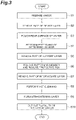
- a wafer 10W having the support layer 11, the device layer 12, and the intermediate layer 13 is prepared (Step S1, first step).
- the wafer 10W has a front surface (first front surface) 10a and a rear surface (second front surface) 10b on a side opposite to the front surface 10a.
- the front surface 10a is a surface serving as the first front surface 2a of the structure 2A.
- the wafer 10W includes a plurality of parts 11W each serving as the structure 2A.
- the part 11W is a part of the wafer 10W before the structure 2A is formed.
- Each step of the method for manufacturing the mirror device 1A is performed at a level of a wafer.
- FIGS. 4 , 5 , 7 , and 9 one part 11W of the wafer 10W is illustrated.
- description will be given focusing on one part 11W of the wafer 10W.
- the first slit 22a and the second slit 23a are formed in the wafer 10W such that the first movable portion 22 and the second movable portion 23 are movable with respect to the base portion 21 by removing a part of each of the support layer 11, the device layer 12, and the intermediate layer 13 from the wafer 10W, and a plurality of parts 12WA (refer to (b) in FIG. 7 ) each corresponding to the structure 2A are formed in the wafer 10W (second step).
- a part 12WA is a part of the wafer 10W in which the structure 2A is formed.
- a part of the device layer 12 is removed from the wafer 10W by etching (Step S2).
- Step S2 parts corresponding to the first slit 22a, the second slit 23a, and the circulation holes 21b, 22b, and 23b in the device layer 12 are removed. As a result, the end surface 12a and the end surface 12b of the device layer 12 are formed.
- the first coil 221 and the second coil 231 as well as an electrode pad, a wiring, and the like for inputting a drive signal to the first coil 221 and the second coil 231 are provided in the device layer 12.
- the mirror layer 3 is formed at a part corresponding to the first movable portion 22 on the front surface 10a of the wafer 10W.
- the mirror layer 3 is formed by vapor deposition of a metal.
- a patterning member used for removing the device layer 12 is removed from the wafer 10W by patterning member removal (which will be described below in detail) for removing a patterning member.
- the rear surface 10b of the wafer 10W is polished (Step S3).
- the wafer 10W is thinned as the rear surface 10b is polished.
- the polished rear surface 10b of the wafer 10W is a surface serving as a part of the second front surface 2b of the structure 2A.
- a patterning member 19 is patterned on the rear surface 10b of the wafer 10W (Step S4). Specifically, the patterning member 19 is provided in a region corresponding to the base portion 21 on the rear surface 10b, that is, a region excluding regions corresponding to the circulation holes 21b.
- the patterning member 19 is a resist or the like.
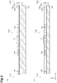
- a part of the support layer 11 is removed from the wafer 10W by etching via the patterning member 19 (Step S5).
- Step S5 a part of the support layer 11 is removed from the wafer 10W such that the end surface 11a and the end surface 11b of the support layer 11 respectively become flush with the end surface 12a and the end surface 12b of the device layer 12.
- a part of the support layer 11 is removed by reactive ion etching using a Bosch process (DRIE).
- DRIE Bosch process
- Step S5 when a part of the support layer 11 is removed from the wafer 10W, a polymer or the like is used as a protective film, for example.
- Step S6 patterning member removal and protective film removal are performed.
- the patterning member removal is a step for removing (peeling) the patterning member 19 from the rear surface 10b of the wafer 10W.
- the patterning member 19 is removed by a wet process. Specifically, first, a plurality of wafers 10W are set inside a carrier 50 exhibiting a box shape.
- a plurality of grooves (not illustrated) arranged at predetermined intervals in the Z axis direction are formed on an inner wall surface of the carrier 50.
- the grooves extend along an XY plane.
- the wafers 10W are fitted into the respective grooves so that the plurality of wafers 10W are disposed in the Z axis direction (the thickness direction of the wafers 10W). That is, different wafers 10W having the same structure as the wafer 10W are respectively disposed on one side and the other side of the wafers 10W in the Z axis direction.
- a second region R2 is formed between the wafer 10W and a different wafer 10W which are adjacent to each other.
- the patterning member 19 is removed in a state in which a patterning member removing liquid is present in the second region R2.
- the plurality of wafers 10W and the different wafers 10W are immersed in the patterning member removing liquid in a state in which the plurality of wafers 10W and the different wafers 10W are set inside the carrier 50.
- the patterning member removing liquid is accommodated in a pool.
- the plurality of wafers 10W and the different wafers 10W are immersed in the patterning member removing liquid such that the direction of an opening of the carrier 50 becomes the same as the direction of a liquid level of the patterning member removing liquid.
- the patterning member removing liquid is a liquid chemical or the like for removing the patterning member 19 from the wafers 10W.
- the plurality of wafers 10W are reciprocated (swing) in the X axis direction (a direction intersecting the thickness direction of the wafers 10W and the liquid level of the patterning member removing liquid). Reciprocating of the plurality of wafers 10W is performed by reciprocating the carrier 50. In the patterning member removal, the plurality of wafers 10W are reciprocated for a second time at a second speed.
- a speed for reciprocating denotes the number of times of reciprocating per unit time. For example, the second speed is approximately 70 times/min. For example, the second time is approximately 40 minutes.
- the second time is a total of times of reciprocating the plurality of wafers 10W at the second speed.
- the kind of the patterning member removing liquid may be varied, or reciprocating of the plurality of wafers 10W may be temporarily stopped.
- the patterning member removal after the patterning member 19 is removed by the wet process, the plurality of wafers 10W are immersed in water for a predetermined time, for example.
- the patterning member removal after the patterning member 19 is removed, namely, after the wafers 10W are immersed in water for a predetermined time, second spin-drying of drying the wafers 10W is performed. In the second spin-drying, the wafers 10W are dried by rotating the wafers 10W for a fourth time at a second rotation speed. After the patterning member removal is performed, the patterning member 19 is removed from the wafers 10W, as illustrated in (a) in FIG. 7 .
- the protective film removal is a step for removing a polymer or the like used as a protective film from the wafers 10W in Step S5.
- the protective film is removed by a wet process using a protective film removing liquid.
- the protective film removing liquid is a liquid chemical or the like for removing a polymer or the like from the wafer 10W.
- Step S7 a part of the intermediate layer 13 is removed from the wafers 10W by etching. Specifically, in the intermediate layer 13, a part on a side inward from a part corresponding to the base portion 21 and parts corresponding to the circulation holes 21b are removed. As a result, the first slit 22a and the second slit 23a are formed. At this time, the end surface 13a of the intermediate layer 13 is formed.
- Step S7 the plurality of parts 12WA each corresponding to the structure 2A are formed in the wafers 10W by forming the first slit 22a and the second slit 23a in the wafers 10W such that the first movable portion 22 and the second movable portion 23 are movable with respect to the base portion 21, and the plurality of parts 12WA are brought to completion. Namely, a plurality of first movable portions 22 and a plurality of second movable portions 23 are released.
- released denotes that the first movable portion or the second movable portion is shifted from a fixed state to a movable state with respect to the base portion.
- Step S7 the first slit 22a and the second slit 23a are formed such that each of the first movable portions 22 and the second movable portions 23 is supported on the base portion 21 by each of the first coupling portions 24 and each of the second coupling portions 25.
- the plurality of circulation holes 21b, 22b, and 23b penetrating the wafer 10W are formed at parts other than the first slit 22a and the second slit 23a in the wafers 10W by removing a part of the intermediate layer 13 from the wafers 10W.
- the circulation holes 21b penetrating the wafer 10W are formed at parts corresponding to the base portion 21 in the wafers 10W
- the circulation holes 22b penetrating the wafer 10W are formed at parts corresponding to the first movable portions 22
- the circulation holes 23b penetrating the wafer 10W are formed at a part corresponding to the second movable portion 23.
- the end surface 13b of the intermediate layer 13 is formed.
- Step S7 etching is performed such that the end surface 13a of the intermediate layer 13 is not recessed with respect to both the end surface 11a of the support layer 11 and the end surface 12a of the device layer 12. In Step S7, etching is performed such that the end surface 13a of the intermediate layer 13 becomes flush with the end surface 11a of the support layer 11 and the end surface 12a of the device layer 12. Similarly, in Step S7, etching is performed such that the end surface 13b of the intermediate layer 13 is not recessed with respect to both the end surface 11b of the support layer 11 and the end surface 12b of the device layer 12.
- Step S7 etching is performed such that the end surface 13b of the intermediate layer 13 becomes flush with the end surface 11b of the support layer 11 and the end surface 12b of the device layer 12.
- Step S7 a part of the intermediate layer 13 is removed from the wafers 10W by anisotropic etching.
- Step S7 a part of the intermediate layer 13 is removed from the wafers 10W by dry etching.
- Step S8 wet cleaning is performed (Step S8, third step).
- the wet cleaning is cleaning for removing a foreign substance or the like adhered to the wafers 10W.
- the wafers 10W are cleaned using a cleaning liquid (not illustrated).
- a plurality of wafers 10W and a plurality of dummy wafers (monitoring wafers) 20W are set inside a carrier 60 exhibiting a box shape.
- the thicknesses of the dummy wafer 20W is approximately 625 ⁇ m.
- a plurality of grooves (not illustrated) arranged at predetermined intervals in the Z axis direction are formed on an inner wall surface of the carrier 60.
- the grooves extend along an XY plane.
- the wafers 10W and the dummy wafers 20W are fitted into the respective grooves so that the plurality of wafers 10W and the plurality of dummy wafers 20W are alternately disposed in the Z axis direction (the thickness direction of the wafers 10W and the dummy wafers 20W). That is, the dummy wafers 20W are respectively disposed on one side and the other side of the wafers 10W in the Z axis direction.
- a first region R1 is formed between the wafer 10W and the dummy wafer 20W which are adjacent to each other. The width of the first region R1 in the Z axis direction is larger than the width of the second region R2 in the Z axis direction.
- the wafers 10W are cleaned in a state in which the cleaning liquid is present in the first region R1.
- the plurality of wafers 10W and the plurality of dummy wafers 20W are immersed in the cleaning liquid in a state in which the plurality of wafers 10W and the plurality of dummy wafers 20W are set inside the carrier 60.
- the cleaning liquid is accommodated in a pool.
- the plurality of wafers 10W and the plurality of dummy wafers 20W are immersed in the cleaning liquid such that the direction of an opening of the carrier 60 becomes the same as the direction of a liquid level of the cleaning liquid.
- the cleaning liquid is a liquid chemical or the like for removing a foreign substance or the like from the wafers 10W.
- the plurality of wafers 10W and the plurality of dummy wafers 20W are immersed in the cleaning liquid, the plurality of wafers 10W and the plurality of dummy wafers 20W are reciprocated (swing) in the X axis direction (a direction intersecting the thickness direction of the wafers 10W and the liquid level of the cleaning liquid). Reciprocating of the plurality of wafers 10W and the plurality of dummy wafers 20W is performed by reciprocating the carrier 60.
- the plurality of wafers 10W and the plurality of dummy wafers 20W are reciprocated for a first time at a first speed.
- a load applied to the wafers 10W during the wet cleaning in Step S8 is smaller than a load applied to the wafers 10W during the patterning member removal in Step S6.
- the intensity of the wet cleaning in Step S8 is smaller than the intensity of the patterning member removal in Step S6.
- a load applied to the wafers 10W during the wet cleaning in Step S8 is smaller than a load applied to the wafers 10W during the protective film removal in Step S6.
- the intensity of the wet cleaning in Step S8 is smaller than the intensity of the protective film removal in Step S6.
- a load applied to the wafers denotes a magnitude of mechanical work (energy) applied to wafers.
- energy energy
- the higher the speed of reciprocating the wafers 10W the greater the load applied to the wafers 10W.
- the longer the time of reciprocating the wafers 10W the greater the load applied to the wafers 10W.
- the first speed is lower than the second speed.
- the first speed is approximately 40 times/min.
- the first time is shorter than the second time.
- the first time is approximately 20 minutes.
- the first time is a total of times of reciprocating the plurality of wafers 10W and the plurality of dummy wafers 20W at the first speed.
- the kind of the cleaning liquid may be varied, or reciprocating of the plurality of wafers 10W and the plurality of dummy wafers 20W may be temporarily stopped.
- the plurality of wafers 10W and the plurality of dummy wafers 20W are immersed in water for a predetermined time, for example.
- first spin-drying of drying the wafers 10W is performed.
- the wafers 10W are rotated for a third time at a first rotation speed.
- a load applied to the wafers 10W during the first spin-drying in Step S8 is smaller than a load applied to the wafers 10W during the second spin-drying in Step S6.
- the intensity of the first spin-drying in Step S8 is smaller than the intensity of the second spin-drying in Step S6.
- the higher the rotation speed of rotating the wafers 10W the greater the load applied to the wafers 10W.
- the longer the time of rotating the wafers 10W the greater the load applied to the wafers 10W.
- the first rotation speed is lower than the second rotation speed.
- the first rotation speed is approximately 200 rpm.
- the third time is approximately five minutes.
- the straightening layer 4 is formed on the rear surface 10b on a side opposite to the front surface 10a, of surfaces of the wafer 10W, where the mirror layer 3 is formed (Step S9, fifth step).
- the straightening layer 4 is formed on a surface on a side opposite to the mirror layer 3 in each of the support layer 11 and the device layer 12.
- each of the plurality of parts 12WA are cut out from the wafer 10W (Step S10, fourth step). Accordingly, a plurality of mirror devices 1A are manufactured.
- Step S8 the wafers 10W, in which the plurality of first movable portions 22 and second movable portions 23 are released, are cleaned with the cleaning liquid. Accordingly, a foreign substance can be removed from the wafers 10W in which the plurality of first movable portions 22 and second movable portions 23 are released.
- the wafers 10W, in which the plurality of first movable portions 22 and second movable portions 23 are released are cleaned by the wet cleaning in Step S8, the plurality of first movable portions 22 and second movable portions 23 are likely to be damaged.
- Step S7 (second step) each of the circulation holes 21b, 22b, and 23b penetrating the wafer 10W is formed at parts other than the first slit 22a and the second slit 23a in the wafer 10W by etching.
- the wafers 10W in which the plurality of first movable portions 22 and second movable portions 23 are released can be cleaned. Therefore, a load received by the plurality of first movable portions 22 and second movable portions 23 due to the cleaning liquid can be reduced, and occurrence of damage to the plurality of first movable portions 22 and second movable portions 23 can be curbed.
- the cleaning liquid is easily circulated via the circulation holes 21b, 22b, and 23b between one side and the other side of the wafer 10W in the Z axis direction. For this reason, cleaning efficiency in the wet cleaning is improved.
- Step S2 the mirror layer 3 is formed to the wafer 10W at a part corresponding to the first movable portion 22. Accordingly, a foreign substance adhered to the mirror layer 3 can be removed by the wet cleaning in Step S8.
- the method for manufacturing the mirror device 1A includes Step S9 of forming the straightening layer 4 on the rear surface 10b of the wafer 10W between Step S8 and Step S10. Accordingly, covering of a foreign substance by the straightening layer 4 can be curbed.
- Step S6 protective film removal for removing a protective film is performed after a part of the support layer 11 is removed from the wafer 10W, and the plurality of parts 12WA are brought to completion after the protective film removal.
- the protective film is removed by the wet process.
- a polymer or the like is used as the protective film. The polymer may remain in the wafer 10W after a part of the support layer 11 is removed from the wafer 10W.
- the protective film removing liquid may remain on the front surface of the mirror layer 3 or the like formed in the wafer 10W.
- stain may occur.
- a polymer, stain, or the like remains in the wafer 10W, there is concern that the presence of the polymer, stain, or the like may cause poor appearance of the mirror device 1A and the yield thereof may decrease.
- a polymer (foreign substance) or the like remaining in the wafer 10W can be removed by the protective film removal when a part of the support layer 11 is removed from the wafer 10W.
- stain (foreign substance) or the like remaining in the wafer 10W can be removed by the wet cleaning in Step S8 when the protective film is removed. Accordingly, decrease in yield due to poor appearance of the mirror device 1A can be curbed.
- Step S6 patterning member removal for removing the patterning member 19 is performed, and the plurality of parts 12WA are brought to completion after the patterning member removal. Accordingly, since the patterning member 19 is removed before the plurality of first movable portions 22 and second movable portions 23 are released, occurrence of damage to the mirror device 1A due to the patterning member removal can be curbed.
- the patterning member 19 is removed by the wet process. Accordingly, since the patterning member 19 is removed before the plurality of first movable portions 22 and second movable portions 23 are released, even if the patterning member 19 is removed by the wet process, occurrence of damage to the mirror device 1A can be curbed.
- the plurality of circulation holes 22b and the plurality of circulation holes 23b are formed at parts respectively corresponding to the first movable portion 22 and the second movable portion 23. Accordingly, during the wet cleaning in Step S8, a turbulent flow of the cleaning liquid is likely to be generated in the vicinity of the first movable portion 22 and the second movable portion 23. Therefore, a foreign substance can be reliably removed from parts corresponding to the first movable portion 22 and the second movable portion 23. In addition, a foreign substance can be reliably removed from the mirror layer 3.
- the circulation holes 21b are formed at a part corresponding to the base portion 21. Accordingly, during the wet cleaning in Step S8, a larger amount of cleaning liquid can be circulated via the circulation holes 21b in addition to the circulation holes 22b and 23b. Therefore, a load received by the wafer 10W due to the cleaning liquid can be more reliably reduced, and occurrence of damage to the wafer 10W can be more reliably curbed. In addition, cleaning efficiency in the wet cleaning is reliably improved.
- a mirror device 1B of a second embodiment mainly differs from the mirror device 1A of the first embodiment in that a beam portion 5 is provided in place of the straightening layer 4.
- the mirror device 1B is otherwise similar to the mirror device 1A, and thus detailed description thereof will be omitted.
- a structure 2B of the mirror device 1B includes a plurality of beam portions 5.
- Each beam portion 5 is constituted of the support layer 11 and a part of the intermediate layer 13.
- the beam portion 5 is provided in the first movable portion 22.
- the beam portion 5 is provided on a surface on a side opposite to the mirror layer 3 of the device layer 12.
- the beam portion 5 linearly extends in the Y axis direction.
- the plurality of beam portions 5 are arranged at predetermined intervals in the X axis direction.
- the plurality of beam portions 5 may be disposed such that they exhibit radial shapes, for example, when viewed in the Z axis direction.
- the structure 2B may include one beam portion 5.
- the beam portion 5 may exhibit a circular ring shape, for example, when viewed in the Z axis direction. Namely, the beam portion 5 may exhibit a cylindrical shape. The beam portion 5 may exhibit various shapes.
- the beam portion 5 is provided so as to reinforce the structure 2B.
- an end surface 11c of the support layer 11 is formed such that it is not recessed with respect to an end surface 13c of the intermediate layer 13. The end surface 11c of the support layer 11 and the end surface 13c of the intermediate layer 13 are flush with each other.
- the end surface 11c of the support layer 11 and the end surface 13c of the intermediate layer 13 are positioned on a side inward from an end surface 22c of the first movable portion 22 (an end surface where the circulation holes 22b are formed).
- the method for manufacturing the mirror device 1B mainly differs from the method for manufacturing the mirror device 1A of the first embodiment in that the beam portions 5 are formed in place of the straightening layer 4.
- the method for manufacturing the mirror device 1B is otherwise similar to the method for manufacturing the mirror device 1A of the first embodiment, and thus detailed description thereof will be omitted.
- the wafer 10W is prepared (Step S21, first step). Subsequently, similar to the first embodiment, the first slit 22a and the second slit 23a are formed in the wafer 10W such that the first movable portion 22 and the second movable portion 23 are movable with respect to the base portion 21 by removing a part of each of the support layer 11, the device layer 12, and the intermediate layer 13 from the wafer 10W by etching, and a plurality of parts 12WB (refer to (a) in FIG. 15 ) each corresponding to the structure 2B are formed in the wafer 10W (second step).
- Step S22 a part of the device layer 12 is removed from the wafer 10W by etching.
- Step S22 the first coil 221, the second coil 231, an electrode pad, a wiring, and the like are provided in the device layer 12, and the mirror layer 3 is formed on the front surface 10a of the wafer 10W.
- Step S3 similar to Step S3 (refer to (b) in FIG. 4 ) of the first embodiment, the rear surface 10b of the wafer 10W is polished (Step S23).
- Step S24 a patterning member 29 is patterned on the rear surface 10b of the wafer 10W.
- Step S25 a part of the support layer 11 is removed from the wafer 10W by etching via the patterning member 29.
- Step S25 only a part of the support layer 11 in the thickness direction is removed.
- Step S25 is otherwise similar to Step S5 of the first embodiment.
- Step S6 similar to Step S6 (refer to FIG. 6 ) of the first embodiment, patterning member removal and protective film removal are performed (Step S26). After the patterning member removal is performed, the patterning member 29 is removed from the wafer 10W, as illustrated in (a) in FIG. 13 .
- a patterning member 39 is patterned on the rear surface 10b of the wafer 10W (Step S27). Specifically, the patterning member 39 is provided in a region corresponding to the base portion 21 on the rear surface 10b, that is, a region excluding the region corresponding to the circulation holes 21b and a region corresponding to the beam portion 5 on the rear surface 10b. Subsequently, as illustrated in (a) in FIG. 14 , a part of the support layer 11 is removed from the wafer 10W by etching via the patterning member 39 (Step S28).
- Step S29 the patterning member removal is performed again.
- the patterning member 39 is removed from the wafer 10W, as illustrated in (b) in FIG. 14 .
- Step S30 a part of the intermediate layer 13 is removed from the wafer 10W by etching. Specifically, a part on a side inward from a part corresponding to the base portion 21 in the intermediate layer 13, that is, parts excluding parts corresponding to the beam portions 5 and parts corresponding to the circulation holes 21b are removed. As a result, the end surface 13c of the intermediate layer 13 is formed.
- Step S30 etching is performed such that the end surface 13c of the intermediate layer 13 is not recessed with respect to the end surface 11c of the support layer 11.
- Step S30 etching is performed such that the end surface 13c of the intermediate layer 13 is flush with the end surface 11c of the support layer 11.
- the wet cleaning is performed (Step S31, the third step).
- Step S32 the fourth step. Accordingly, a plurality of mirror devices 1B are manufactured.
- Step S30 (second step) etching is performed such that the end surface 13c of the intermediate layer 13 is not recessed with respect to the end surface 11c of the support layer 11. For this reason, the beam portions 5 are unlikely to peel from the first movable portion 22. If the end surface 13c of the intermediate layer 13 is recessed with respect to the end surface 11c of the support layer 11, the beam portions 5 peel from the first movable portion 22. As a result, there is concern that the structure 2B may break. Here, since the beam portions 5 are unlikely to peel from the first movable portion 22, breakage of the structure 2B is curbed. After Step S30, since the wet cleaning is performed in Step S31, it is particularly important that the beam portions 5 be unlikely to peel from the first movable portion 22.
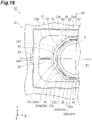
- a mirror device 1C of a third embodiment mainly differs from the mirror device 1A of the first embodiment in that the circulation holes 22b include a first circulation region 22d and second circulation regions 22e, the circulation holes 23b communicate with the first slit 22a, and circulation holes 25b are formed in the second coupling portions 25.
- the circulation holes 22b include a first circulation region 22d and second circulation regions 22e
- the circulation holes 23b communicate with the first slit 22a
- circulation holes 25b are formed in the second coupling portions 25.
- the first movable portion 22 of a structure 2C exhibits an N-polygonal shape (N is a natural number of 4 or larger), for example, when viewed in the Z axis direction. N is preferably a natural number of 5 or larger.
- the first movable portion 22 exhibits an octagonal shape, for example, when viewed in the Z axis direction.
- the first movable portion 22 may exhibit a circular shape, for example, when viewed in the Z axis direction.
- the second coupling portions 25 are disposed on both sides of the second movable portion 23 in the X axis direction.
- the circulation holes 22b formed in the first movable portion 22 include the first circulation region 22d and a plurality of second circulation regions 22e.
- the first circulation region 22d extends along the outer edge of the first movable portion 22 when viewed in the Z axis direction.
- the first circulation region 22d exhibits a ring shape, for example, when viewed in the Z axis direction.
- a plurality of connection portions 26 straddling the first circulation region 22d therebetween are formed in the first movable portion 22. Accordingly, the first circulation region 22d are divided into a plurality of regions arranged along the outer edge of the first movable portion 22.
- the connection portions 26 are arranged in a circumferential direction of the first circulation region 22d when viewed in the Z axis direction.
- the plurality of second circulation regions 22e are positioned on the outward side of the first circulation region 22d when viewed in the Z axis direction.
- the plurality of second circulation regions 22e are arranged along the outer edge of the first movable portion 22 when viewed in the Z axis direction.
- Each of the second circulation regions 22e extends along the outer edge of the first movable portion 22 (each side of an octagon) when viewed in the Z axis direction. In this manner, the first circulation region 22d and the second circulation regions 22e are adjacent to each other in a direction perpendicular to the Z axis direction.
- a direction perpendicular to the Z axis direction denotes a direction in a direction toward the outward side of the first circulation region from the inward side of the first circulation region when viewed in the Z axis direction.
- a direction perpendicular to the Z axis direction is a direction perpendicular to the outer edge of the first movable portion 22 when viewed in the Z axis direction.
- a direction perpendicular to the Z axis direction is a radial direction of the first movable portion 22 when viewed in the Z axis direction.
- a direction perpendicular to the Z axis direction will be referred to as "a radial direction”.
- the widths of the second circulation regions 22e in the radial direction are smaller than the width of the first circulation region 22d in the radial direction.
- the second circulation regions 22e may include a part of which the width in the radial direction is smaller than the width of the first circulation region 22d in the radial direction.
- the second circulation regions 22e may include a part of which the width in the radial direction is equal to or larger than the width of the first circulation region 22d in the radial direction.
- the circulation holes (auxiliary circulation regions) 23b formed in the second movable portion 23 communicate with the first slit 22a.
- the circulation holes 23b are formed due to a part of the first slit 22a expanding toward a side opposite to the first movable portion 22 in the X axis direction.
- the region constituted of the first slit 22a and the circulation holes 23b has a rectangular external shape, for example, when viewed in the Z axis direction.
- a boundary line between the circulation holes 23b and the first slit 22a is indicated by a dotted line.
- a pair of circulation holes 25b are formed in each of the second coupling portions 25. In each of the second coupling portions 25, the pair of circulation holes 25b are arranged in the Y axis direction. Each of the circulation holes 25b penetrates the second coupling portion 25.
- a part on the inward side of first circulation region 22d in the first movable portion 22 constitutes a main body portion 30.
- a part on the outward side of the first circulation region 22d in the first movable portion 22 constitutes a ring-shaped portion 40.
- the main body portion 30 exhibits a circular shape in a plan view, but it may be formed to have an arbitrary shape such as an oval shape, a quadrangular shape, or a rhombic shape.
- the center of the main body portion 30 in a plan view coincides with the intersection between the first axis X1 and the second axis X2.
- the ring-shaped portion 40 is formed to have a ring shape such that the main body portion 30 is surrounded via the first circulation region 22d in a plan view.
- the ring-shaped portion 40 has an outer edge and an inner edge having an octagonal shape in a plan view.
- the plurality of connection portions 26 couple the main body portion 30 and the ring-shaped portion 40 to each other.
- the ring-shaped portion 40 has a pair of first parts 41, a pair of second parts 42, and two pairs of third parts (inclined portions) 43.
- the pair of first parts 41 are positioned on the both sides of the main body portion 30 in X axis direction. Each of the first parts 41 extends in the Y axis direction.
- the pair of second parts 42 are positioned on both sides of the main body portion 30 in the Y axis direction. Each of the second parts 42 extends in the X axis direction.
- Each of the two pairs of third parts 43 is positioned between the first parts 41 and the second parts 42 and is connected to the first parts 41 and the second parts 42.
- Each of the third parts 43 extends in a direction intersecting the X axis direction and the Y axis direction. Each of the third parts 43 obliquely intersects the center lines (first axis X1) of the first coupling portions 24 and the second coupling portions 25.
- each of the third parts 43 can be brought closer to the first axis X1. For this reason, the moment of inertia of the first movable portion 22 around the first axis X1 can be reduced by concentrating the mass of the first movable portion 22 in a region close to the first axis X1.
- the moment of inertia of the first movable portion 22 around the first axis X1 can be reduced by concentrating the mass of the first movable portion 22 in a region close to the first axis X1. Accordingly, driving power for driving the first movable portion 22 can be reduced.
- the second circulation regions 22e are respectively formed in the first parts 41.
- Each of the first parts 41 has a first frame portion 41a on a side opposite to the main body portion 30 with respect to the second circulation regions 22e, and a second frame portion 41b on a side opposite to the first frame portion 41a with respect to the second circulation regions 22e.
- the first frame portion 41a is a part on the outward side of the second circulation regions 22e in the first movable portion 22.
- the second frame portion 41b is a part between the first circulation region 22d and the second circulation regions 22e in the first movable portion 22.
- the first frame portion 41a and the second frame portion 41b extend along the second circulation regions 22e.
- a width D1 of the first frame portion 41a in the radial direction is substantially the same as a width D2 of the second frame portion 41b in the radial direction.
- the second circulation region 22e is disposed in a line-symmetrical manner about the first axis X1. Namely, in each of the first parts 41, the second circulation region 22e is formed at a position adjacent to the first coupling portion 24 on the center line of the first coupling portion 24 and the second coupling portion 25. Accordingly, for example, when a stress occurs in the first coupling portions 24 or the second coupling portions 25, and when the stress is transferred to the first movable portion 22, parts in the vicinity of the second circulation regions 22e in the first parts 41 are locally distorted. As a result, transfer of the stress to the main body portion 30 of the first movable portion 22 is curbed. Accordingly, distortion or the like of the mirror layer 3 can be curbed.
- the second circulation regions 22e are respectively formed in the second parts 42.
- Each of the second parts 42 has a first frame portion 42a on a side opposite to the main body portion 30 with respect to the second circulation region 22e, and a second frame portion 42b on a side opposite to the first frame portion 42a with respect to the second circulation region 22e.
- the first frame portion 42a is a part on the outward side of the second circulation region 22e in the first movable portion 22.
- the second frame portion 42b is a part between the first circulation region 22d and the second circulation region 22e in the first movable portion 22.
- the first frame portion 42a and the second frame portion 42b extend along the second circulation region 22e.
- a width D3 of the first frame portion 42a in the radial direction is larger than a width D4 of the second frame portion 42b in the radial direction.
- the second circulation region 22e is formed at a position away from the center lines of the first coupling portions 24 and the second coupling portions 25.
- Each second frame portion 42b functions as a stress relaxation region. Specifically, for example, when the first movable portion 22 receives a stress from the outside, the second frame portion 42b is locally distorted. As a result, transfer of the stress to the main body portion 30 of the first movable portion 22 is curbed. Accordingly, distortion or the like of the mirror layer 3 can be curbed.
- connection portion 26 couples the second frame portion 42b and the main body portion 30 to each other.
- the connection portion 26 straddles the first circulation region 22d therebetween in the radial direction (a direction in which the first circulation region 22d and the second circulation region 22e are arranged).
- the connection portion 26 straddles a part of the first circulation region 22d overlapping the second circulation region 22e in the radial direction.
- the connection portion 26 coupling the second part 42 and the main body portion 30 to each other is formed in the first circulation region 22d on a side opposite to the first coupling portion 24 with respect to the third part 43.
- connection portion 26 is adjacent to the second circulation region 22e in the radial direction. Namely, the connection portion 26 is formed in a manner corresponding to the second circulation region 22e.
- connection portion 26 is coupled to the second frame portion 42b substantially at a central position of the second circulation region 22e in the X axis direction. Accordingly, the second frame portion 42b can be uniformly disposed on both sides of the connection portion 26 in the X axis direction. For this reason, transfer of a stress to the main body portion 30 of the first movable portion 22 can be efficiently curbed.
- the second circulation regions 22e are respectively formed in the third parts 43.
- Each of the third parts 43 has a first frame portion 43a on a side opposite to the main body portion 30 with respect to the second circulation region 22e, and a second frame portion 43b on a side opposite to the first frame portion 43a with respect to the second circulation region 22e.
- the first frame portion 43a is a part on the outward side of the second circulation region 22e in the first movable portion 22.
- the second frame portion 43b is a part between the first circulation region 22d and the second circulation region 22e in the first movable portion 22.
- the first frame portion 43a and the second frame portion 43b extend along the second circulation region 22e.
- a width D5 of the first frame portion 43a in the radial direction is larger than a width D6 of the second frame portion 43b in the radial direction.
- Each second frame portion 43b functions as a stress relaxation region. Specifically, for example, when the first movable portion 22 receives a stress from the outside, the second frame portion 43b is locally distorted. As a result, transfer of the stress to the main body portion 30 of the first movable portion 22 is curbed. Accordingly, distortion or the like of the mirror layer 3 can be curbed.
- connection portion 26 couples the second frame portion 43b and the main body portion 30 to each other.
- the connection portion 26 straddles the first circulation region 22d therebetween in the radial direction (a direction in which the first circulation region 22d and the second circulation region 22e are arranged).
- the connection portion 26 straddles a part of the first circulation region 22d overlapping the second circulation region 22e in the radial direction.
- connection portion 26 coupling the third part 43 and the main body portion 30 to each other is formed in the first circulation region 22d between the first coupling portion 24 and the connection portion 26 coupling the second part 42 and the main body portion 30 to each other.
- the connection portion 26 coupling the third part 43 and the main body portion 30 to each other is formed at a part overlapping the third part 43 of the first circulation region 22d.
- connection portion 26 is adjacent to the second circulation region 22e in the radial direction. Namely, the connection portion 26 is formed in a manner corresponding to the second circulation region 22e.
- the connection portion 26 is coupled to the second frame portion 43b at a position on a side opposite to the first coupling portion 24 with respect to center lines X3 of the second circulation region 22e.
- the connection portion 26 is formed at a part on a side opposite to the first coupling portion 24 at a part of the first circulation region 22d overlapping the second circulation region 22e in the radial direction.
- connection portion 26 is coupled to the second frame portion 43b at a position away from the first coupling portion 24. Accordingly, in each of the third parts 43, a distance from an end of the second frame portion 43b on the first coupling portion 24 side (an end close to the first coupling portion 24) to the connection portion 26 becomes long. Namely, in the second frame portion 43b, a region in which a stress transferred from the first coupling portion 24 is relaxed becomes long. For this reason, for example, transfer of a stress transferred from the first coupling portions 24 to the main body portion 30 of the first movable portion 22 via the connection portions 26 is effectively curbed. Accordingly, distortion or the like of the mirror layer 3 can be effectively curbed.
- the center lines X3 are lines passing through the centers of the second circulation regions 22e in an extending direction in the third parts 43 and extending in the radial direction.
- connection portion 26 may not be formed at a part of the first circulation region 22d overlapping the third part 43.
- the connection portion 26 may be formed at a part of the first circulation region 22d on the first coupling portion 24 side from the third part 43.
- the first movable portion 22 When the first movable portion 22 exhibits an N-polygonal shape viewed in the Z axis direction, as N becomes larger (for example, when N is 8), compared to when the first movable portion 22 exhibits a rectangular shape, for example, a distance between a pair of connection portions 26 coupling each of the second parts 42 and the main body portion 30 to each other and the first coupling portions 24 (a distance along the outer edge of the first movable portion 22) becomes short. As a result, there is concern that a stress transferred from the first coupling portions 24 to the main body portion 30 via the pair of connection portions 26 may increase.
- connection portions 26 not only between the pair of connection portions 26 but also between the connection portions 26 and the first coupling portions 24 as described above.
- connection portions 26 between the third parts 43 different from the second parts 42 and the main body portion 30. Since each of the connection portions 26 couples each of the second parts 42 and the third parts 43 to the main body portion 30, a stress transferred from the first coupling portions 24 to the main body portion 30 can be further reduced.
- the pair of second parts 42 and the two pairs of third parts 43 are coupled to the main body portion 30 by three pairs of connection portions 26.
- the first coil 221 of the mirror device 1C extends in a spiral shape on a side outward from the first circulation region 22d (the outer edge portion of the first movable portion 22) when viewed in the Z axis direction. Specifically, the first coil 221 is disposed between the first circulation region 22d and the second circulation region 22e (between the first circulation region 22d and the second circulation region 22e present on the first axis X1) in each of the first parts 41 and is disposed on a side outward from the second circulation region 22e (between the second circulation region 22e and the outer edge of the first movable portion 22 provided in a manner corresponding to the connection portion 26) in each of the second parts 42 and each of the third parts 43.
- the first coil 221 is provided in the second frame portion 41b in each of the first parts 41 and is provided in the first frame portion 42a and the first frame portion 43a in each of the second parts 42 and each of the third parts 43.
- the first coil 221 is a drive coil and/or a sensing coil.
- the first frame portion 41a is present between the first coupling portion 24 and the first coil 221. Therefore, for example, transfer of a stress which has occurred in the first coupling portions 24 or the second coupling portions 25 to the first coil 221 is curbed. Accordingly, damage to the first coil 221 can be prevented.
- the first coil 221 is disposed in the first frame portion 42a and the first frame portion 43a in each of the second parts 42 and each of the third parts 43, the second frame portion 42b and the second frame portion 43b functioning as the stress relaxation regions which are relatively easily distorted can be avoided, and thus damage to the first coil 221 can be prevented.
- the width D4 of the second frame portion 42b in the radial direction and the width D6 of the second frame portion 43b in the radial direction can be sufficiently reduced, and thus the functions of the second frame portion 42b and the second frame portion 43b as the stress relaxation regions can be sufficiently exhibited.
- the method for manufacturing the mirror device 1C mainly differs from the method for manufacturing the mirror device 1A of the first embodiment in that the circulation holes 22b including the first circulation region 22d and the second circulation regions 22e are formed, the circulation holes 23b communicating with the first slit 22a is formed, and the circulation holes 25b are formed in the second coupling portions 25.
- the circulation holes 22b including the first circulation region 22d and the second circulation regions 22e are formed, the circulation holes 23b communicating with the first slit 22a is formed, and the circulation holes 25b are formed in the second coupling portions 25.
- the second step parts in the device layer corresponding to the first slit 22a and the second slit 23a, a region excluding the connection portions 26 in the first circulation region 22d, the second circulation regions 22e, the circulation holes 23b, and the circulation holes 25b are removed.
- a part on a side inward from a part corresponding to the base portion 21 in the intermediate layer is removed.
- the first slit 22a and the second slit 23a are formed, and the plurality of first movable portions 22 and the plurality of second movable portions 23 are released.
- the plurality of circulation holes 22b, 23b, and 25b penetrating the wafer are formed at parts other than the first slit 22a and the second slit 23a in the wafer by removing a part of the intermediate layer 13 from the wafer.
- the circulation holes 22b penetrating the wafer are formed at parts corresponding to the first movable portions 22 in the wafer
- the circulation holes 23b penetrating the wafer are formed at parts corresponding to the second movable portion 23
- the circulation hole 25b penetrating the wafer are formed at parts corresponding to the second coupling portions 25.
- the circulation holes 23b are formed such that the circulation holes 23b communicate with the first slit 22a.
- the circulation holes 22b are formed at parts corresponding to the first movable portions 22 such that the circulation holes 22b include the first circulation region 22d and the second circulation regions 22e which are adjacent to each other in the radial direction.
- the circulation holes 22b are formed such that the connection portions 26 straddling the first circulation region 22d therebetween are formed in the radial direction.
- the circulation holes 22b are formed to include a part where the widths of the second circulation regions 22e in the radial direction is smaller than the width of the first circulation region 22d in the radial direction.
- the first slit 22a is formed such that the first movable portion 22 is supported on the base portion 21 by the first coupling portions 24.
- the second circulation regions 22e are formed such that the second circulation regions 22e are adjacent to the first coupling portions 24 in the radial direction.
- the second slit 23a is formed such that the second movable portion 23 is supported on the base portion 21 by the second coupling portions 25.
- the circulation holes 25b are formed at parts corresponding to the second coupling portions 25.
- Step S7 the first slit 22a and the second slit 23a are formed such that the first movable portion 22 and the second movable portion 23 are respectively supported on the base portion 21 by the first coupling portions 24 and the second coupling portions 25 and the circulation holes 25b are formed at parts corresponding to the second coupling portions 25. Accordingly, during the wet cleaning in Step S7, a turbulent flow of the cleaning liquid is likely to be generated in the vicinity of the second coupling portions 25. Therefore, while the intensity of the second coupling portions 25 is maintained, a foreign substance can be reliably removed from parts corresponding to the second coupling portions 25.
- Step S7 the circulation holes 23b are formed such that the circulation holes 23b communicate with the first slit 22a. Accordingly, during the wet cleaning in Step S7, a larger amount of cleaning liquid can be circulated via the circulation holes 23b.
- the circulation holes 22b are formed at a part corresponding to the first movable portion 22 such that the circulation holes 22b include the first circulation region 22d and the second circulation region 22e adjacent to each other in the radial direction when viewed in the Z axis direction. Accordingly, during the wet cleaning in Step S8, a turbulent flow of the cleaning liquid is likely to be generated at a place where the first circulation region 22d and the second circulation region 22e are adjacent to each other. Therefore, a foreign substance can be reliably removed from the wafer 10W.
- the circulation holes 22b are formed such that the connection portions 26 straddling the first circulation region 22d are formed in the radial direction when viewed in the Z axis direction. Accordingly, during the wet cleaning in Step S8, the wafer 10W is reinforced by the connection portions 26. Therefore, occurrence of damage to the wafer 10W can be curbed. In addition, during the wet cleaning in Step S8, the cleaning liquid can be circulated via the second circulation region 22e. Therefore, a load received by the connection portions 26 due to the cleaning liquid can be reduced, and occurrence of damage to the connection portions 26 can be curbed.
- the circulation holes 22b are formed such that the second circulation region 22e includes a part where the width of the second circulation region 22e in the radial direction is smaller than the width of the first circulation region 22d in the radial direction when viewed in the Z axis direction. Accordingly, the width of the first circulation region 22d and the width of the second circulation region 22e differ from each other. Therefore, a turbulent flow of the cleaning liquid is likely to be generated during the wet cleaning in Step S8. For this reason, a foreign substance can be reliably removed from the wafer 10W.
- the first slit 22a and the second slit 23a are formed such that the first movable portion 22 and the second movable portion 23 are respectively supported on the base portion 21 by the first coupling portions 24 and the second coupling portions 25, and the second circulation region 22e is formed such that the second circulation region 22e is adjacent to the first coupling portions 24 in a direction in which the first circulation region 22d and the second circulation region 22e are arranged when viewed in the Z axis direction. Accordingly, during the wet cleaning in Step S8, the cleaning liquid can be circulated via the second circulation region 22e. Therefore, a load received by the first coupling portions 24 due to the cleaning liquid can be reduced, and occurrence of damage to the first coupling portions 24 can be curbed.
- a mirror device 1D of a fourth embodiment mainly differs from the mirror device 1A of the first embodiment in that the circulation holes 22f are formed in the first movable portion 22, and the circulation holes 23b communicate with the first slit 22a. Detailed description of parts of the mirror device 1D similar to those of the mirror device 1A will be omitted.
- the circulation holes 22f are formed in the first movable portion 22 of a structure 2D.
- the circulation holes 22f extend along the outer edge of the first movable portion 22 when viewed in the Z axis direction.
- the circulation holes 22f exhibit ring shapes, for example, when viewed in the Z axis direction.
- the plurality of connection portions 26 straddling the circulation holes 22f therebetween are formed.
- four connection portions 26 are formed in the first movable portion 22 in the first movable portion 22 .
- the connection portions 26 are respectively formed on both end portions of the first movable portion 22 in the Y axis direction when viewed in the Z axis direction. Accordingly, the circulation holes 22b are divided into a plurality of regions.
- a part on the inward side of the circulation hole 22f in the first movable portion 22 constitutes the main body portion 30.
- a part on the outward side of the circulation hole 22f in the first movable portion 22 constitutes the ring-shaped portion 40.
- the main body portion 30 exhibits a circular shape in a plan view, but it may be formed to have an arbitrary shape such as an oval shape, a quadrangular shape, or a rhombic shape.
- the center of the main body portion 30 in a plan view coincides with the intersection between the first axis X1 and the second axis X2.
- the ring-shaped portion 40 is formed to have a ring shape such that the main body portion 30 is surrounded via the circulation hole 22f in a plan view.
- the ring-shaped portion 40 has a hexagonal external shape in a plan view, but it may have an arbitrary external shape such as a circular shape, an oval shape, a quadrangular shape, or a rhombic shape.
- the main body portion 30 and the ring-shaped portion 40 are coupled to each other by the plurality of connection portions 26.
- the second movable portion 23 of the mirror device 1D is formed to have a frame shape and is disposed on the inward side of the base portion 21 such that the first movable portion 22 is surrounded.
- the second movable portion 23 has a pair of first connection portions 41A and 41B, a pair of second connection portions 42A and 42B, a pair of first straight portions 43A and 43B, a pair of second straight portions 44A and 44B, a pair of third straight portions 45A and 45B, and a pair of fourth straight portions 46A and 46B.
- the second movable portion 23 has a symmetrical shape about each of the first axis X1 and the second axis X2 in a plan view.
- a state of being symmetrical about the first axis X1 or the second axis X2 denotes a symmetrical state in a plan view.
- the first connection portions 41A and 41B are positioned on both sides of the first movable portion 22 in the X axis direction. That is, each of the first connection portions 41A and 41B has a part facing the first movable portion 22 in the X axis direction in a plan view. Each of the first connection portions 41A and 41B extends in the Y axis direction.
- the second connection portions 42A and 42B are positioned on both sides of the first movable portion 22 in the Y axis direction. That is, each of the second connection portions 42A and 42B has a part facing the first movable portion 22 in the Y axis direction in a plan view. Each of the second connection portions 42A and 42B extends in the X axis direction.
- the first straight portions 43A and 43B are positioned on both sides of the second connection portion 42A in the X axis direction and are connected to the second connection portion 42A. Each of the first straight portions 43A and 43B extends in the X axis direction. The first straight portions 43A and 43B are disposed in a mutually symmetrical manner about the Y axis.
- the second straight portions 44A and 44B are positioned on both sides of the second connection portion 42B in the X axis direction and are connected to the second connection portion 42B. Each of the second straight portions 44A and 44B extends in the X axis direction. The second straight portions 44A and 44B are disposed in a mutually symmetrical manner about the Y axis.
- the third straight portions 45A and 45B are positioned on a side opposite to the second connection portion 42A with respect to each of the first straight portions 43A and 43B and are connected to the first straight portions 43A and 43B and the first connection portions 41A and 41B.
- the third straight portion 45A extends in a direction inclined by 45 degrees with respect to each of the X axis and the Y axis in a plan view.
- the third straight portion 45B extends in a symmetrical manner about the Y axis with respect to the third straight portion 45A.
- the fourth straight portions 46A and 46B are positioned on a side opposite to the second connection portion 42B with respect to each of the second straight portions 44A and 44B and are connected to the second straight portions 44A and 44B and the first connection portions 41A and 41B.
- the fourth straight portion 46A extends in a symmetrical manner about the X axis with respect to the third straight portion 45A.
- the fourth straight portion 46B extends in a symmetrical manner about the Y axis with respect to the fourth straight portion 46A and extends in a symmetrical manner about the X axis with respect to the third straight portion 45B.
- Each of the first coupling portions 24 is connected to the second movable portion 23 in the first connection portions 41A and 41B.
- the width of the end portion of each of the first coupling portions 24 on the first movable portion 22 side expands as it goes closer to the first movable portion 22
- the width of the end portion on the second movable portion 23 side expands as it goes closer to the second movable portion 23.
- Each of the second coupling portions 25 is connected to the second movable portion 23 in the second connection portions 42A and 42B. Each of the second coupling portions 25 extends in a meandering manner in a plan view. Each of the second coupling portions 25 has a plurality of straight portions and a plurality of folded portions. The straight portions extend in the Y axis direction and are disposed in a manner of being arranged in the X axis direction. The folded portions alternately couple both ends of straight portions which are adjacent to each other.
- the circulation holes (auxiliary circulation regions) 23b formed in the second movable portion 23 communicate with the first slit 22a.
- the circulation holes 23b include four first parts 23c and two second parts 23d.
- Each of the first parts 23c is disposed in a mutually line-symmetrical manner about the first axis X1 and the second axis X2 on the outward side of the first movable portion 22 when viewed in the Z axis direction.
- Each of the first parts 23c is formed due to a part of the first slit 22a expanding toward a side opposite to the first movable portion 22 in the X axis direction.
- Each of the second parts 23d is individually positioned between the pair of first parts 23c on both sides of the first movable portion 22 in the Y axis direction. Each of the second parts 23d is formed due to a part of the first slit 22a expanding to a side opposite to the first movable portion 22 in the Y axis direction. Each of the second parts 23d individually communicates with each of the first slits 22a.
- a boundary line between the circulation holes 23b and the first slit 22a is indicated by a dotted line.
- the mirror device 1D further includes a pair of coils 14 and 15.
- Each of the coils 14 and 15 is provided in the second movable portion 23 such that the first movable portion 22 is surrounded and exhibits a spiral shape in a plan view (when viewed in a direction orthogonal to a plane where each of the coils 14 and 15 is disposed).
- Each of the coils 14 and 15 is disposed along a plane including the X axis and the Y axis.
- Each of the coils 14 and 15 is wound around the first movable portion 22 a plurality of times.
- the pair of coils 14 and 15 are disposed in a manner of being alternately arranged in a width direction of the second movable portion 23 in a plan view. No coil is provided in the first movable portion 22.
- the method for manufacturing the mirror device 1D mainly differs from the method for manufacturing the mirror device 1A of the first embodiment in that the circulation holes 22f are formed in the first movable portion 22 and the circulation holes 23b communicating with the first slit 22a are formed. Detailed description of parts of the method for manufacturing the mirror device 1D similar to those of the method for manufacturing the mirror device 1A will be omitted.
- the second step parts corresponding to the first slit 22a, the second slit 23a, the circulation holes 22f, and the circulation holes 23b in the device layer are removed.
- a part on a side inward from a part corresponding to the base portion 21 in the intermediate layer is removed.
- the first slit 22a and the second slit 23a are formed, and the plurality of first movable portions 22 and the plurality of second movable portions 23 are released.
- the plurality of circulation holes 22f and 23b penetrating the wafer are formed at parts other than the first slit 22a and the second slit 23a in the wafer by removing a part of the intermediate layer 13 from the wafer.
- the circulation holes 22f penetrating the wafer are formed at parts corresponding to the first movable portion 22 in the wafer, and the circulation holes 23b penetrating the wafer are formed at parts corresponding to the second movable portion 23 in the wafer.
- occurrence of damage to the mirror device 1D and a foreign substance remaining can be curbed.
- a part of the device layer 12, a part of the support layer 11, and a part of the intermediate layer 13 are removed from the wafer 10W in this order.
- the embodiments are not limited thereto.
- a part of the support layer 11, a part of the device layer 12, and a part of the intermediate layer 13 may be removed from the wafer 10W in this order.
- the patterning member removal and the protective film removal are performed before a part of the intermediate layer 13 is removed from the wafer 10W.
- a part of the support layer 11, a part of the intermediate layer 13, and a part of the device layer 12 may be removed from the wafer 10W in this order.
- the patterning member removal and the protective film removal are performed before a part of the device layer 12 is removed from the wafer 10W.
- the first movable portion 22 and the second movable portion 23 may be released after the patterning member removal and the protective film removal.
- the patterning members 19, 29, and 39 are removed by the wet process in the patterning member removal.
- the patterning members 19, 29, and 39 may be removed from the wafer 10W by a dry process in the patterning member removal.
- the protective film is removed by the wet process in the protective film removal.
- the protective film may be removed from the wafer 10W by the dry process in the protective film removal. In these cases, a part of the device layer 12, a part of the intermediate layer 13, and a part of the support layer 11 may be removed from the wafer 10W in this order.
- the patterning member removal and the protective film removal may be performed after the first movable portion 22 and the second movable portion 23 are released.
- the protective film removal is performed after the patterning member removal is performed has been described.
- the patterning member removal may be performed after the protective film removal is performed.
- first slit 22a, the second slit 23a, and the circulation holes 21b, 22b, and 23b are formed by removing a part on a side inward from a part corresponding to the base portion 21 and parts corresponding to the circulation holes 21b in the intermediate layer 13 .
- the embodiments are not limited thereto.
- the sequence of forming the first slit 22a, the second slit 23a, and the circulation holes 21b, 22b, and 23b may be arbitrary.
- the circulation holes 21b, 22b, and 23b may be formed after the first slit 22a and the second slit 23a are formed, namely, after the first movable portion 22 and the second movable portion 23 are released.
- parts corresponding to the circulation holes 21b, 22b, and 23b may be removed after parts corresponding to the first slit 22a and the second slit 23a in the wafer 10W are removed first.
- the first slit 22a and the second slit 23a may be formed after the circulation holes 21b, 22b, and 23b are formed.
- parts corresponding to the first slit 22a and the second slit 23a may be removed after parts corresponding to the circulation holes 21b, 22b, and 23b in the wafer 10W are removed first.
- the straightening layer 4 may be formed on the front surface 10a of the wafer 10W.
- the straightening layer 4 may be formed on a surface on a side opposite to the intermediate layer 13 in the device layer 12.
- the straightening layer 4 may be formed on a surface on a side opposite to the intermediate layer 13 in the device layer 12 and a surface on a side opposite to the device layer 12 in the mirror layer 3.
- the straightening layer 4 may be formed on the front surface 10a and may be formed on the rear surface 10b. Namely, the straightening layer 4 is formed on the front surface 10a and/or the rear surface 10b.
- the width in the X axis direction (a direction perpendicular to the thickness direction the wafer 10W) may vary when viewed in the Z axis direction. That is, the widths of the circulation holes 22b in the X axis direction may differ from each other at different positions in the Y axis direction when viewed in the Z axis direction. Specifically, in each of the circulation holes 22b, the width of the central portion in the Y axis direction may be larger than the widths of both end portions in the Y axis direction. In each of the circulation holes 22b, at least a part may include a curved portion when viewed in the Z axis direction.
- each of the circulation holes 22b one edge and the other edge in the X axis direction may exhibit different shapes when viewed in the Z axis direction.
- Each of the circulation holes 22b may exhibit a crescent shape surrounding the mirror layer 3 when viewed in the Z axis direction. In these cases, since a complicated water flow is likely to be generated in the vicinity of each of the circulation holes 22b during the wet cleaning in the third step, cleaning efficiency in the wet cleaning is improved.
- each of the circulation holes 22b may be formed such that the width in the X axis direction varies when viewed in the Z axis direction. Accordingly, during the wet cleaning in the third step, a turbulent flow of the cleaning liquid is likely to be generated. Therefore, a foreign substance can be reliably removed from the wafer 10W.
- each of the circulation holes 22b may be formed such that curved portions are included in at least a part. Accordingly, during the wet cleaning in Step S8, a load due to the cleaning liquid received by the curved portions of the circulation holes 22b becomes small. Therefore, occurrence of damage to the mirror device 1A can be curbed.
- each of the circulation holes 22b may be formed such that one edge and the other edge exhibit different shapes when viewed in the Z axis direction. Accordingly, larger circulation holes 22b are formed so that a larger amount of cleaning liquid can be circulated via the circulation holes 22b during the wet cleaning in the third step. For this reason, a foreign substance can be reliably removed from the wafer 10W.
- the structures 2A, 2B, 2C, and 2D may not have the second movable portion 23.
- the first movable portion 22 is disposed on the inward side of the base portion 21 via the first slit 22a when viewed in the Z axis direction.
- Each of the first coupling portions 24 may be individually disposed on both sides of the first movable portion 22 in the Y axis direction when viewed in the Z axis direction.
- the circulation holes 22b may exhibit a circular ring shape centering on the intersection between the first axis X1 and the second axis X2 when viewed in the Z axis direction.
- the connection portions 26 straddling the circulation holes 22b therebetween are formed in the first movable portion 22.
- the connection portions 26 are arranged at equal intervals in the circumferential direction of the circulation holes 22b when viewed in the Z axis direction. Accordingly, the circulation holes 22b are divided into a plurality of regions.
- the first movable portion 22 are point-symmetrical about the intersection between the first axis X1 and the second axis X2 when viewed in the Z axis direction.
- areas occupied by the circulation holes 22b in the first movable portion 22 can be increased.
- a larger amount of cleaning liquid can be circulated via the circulation holes 22b. Accordingly, a foreign substance can be reliably removed from the wafer 10W.
- the first movable portion 22 is point-symmetrical, occurrence of damage to the first movable portion 22 can be curbed during the wet cleaning in the third step.
- the circulation hole 22b may be formed such that the connection portions 26 straddling the circulation hole 22b are formed.
- circulation hole other than the circulation hole 22b may be formed such that coupling portion straddling circulation hole (for example, the circulation hole 23b) other than the circulation hole 22b is formed. Consequently, the wafer 10W is reinforced by the connection portions 26 during the wet cleaning in the third step. Therefore, occurrence of damage to the mirror device 1A can be curbed.
- the first movable portion 22 may exhibit a circular shape when viewed in the Z axis direction.
- the pair of circulation holes 22b may be mutually line-symmetrical about the first axis X1.
- Each of the circulation holes 22b may exhibit a crescent shape surrounding the mirror layer 3 when viewed in the Z axis direction.
- the first movable portion 22 may exhibit an oval shape in which the long axis extends in the Y axis direction when viewed in the Z axis direction.
- the circulation holes 23b may not be formed in the second movable portion 23.
- the circulation holes 22b may not be formed in the first movable portion 22.
- the circulation holes 22b and 23b may not be formed. Namely, the circulation holes 21b may be formed in only the base portion 21.
- a pair of circulation holes 24b may be individually formed on both sides of each of the first coupling portions 24 in the X axis direction.
- Each of the circulation holes 24b penetrates the base portion 21.
- Each of the circulation holes 24b is positioned on a side inward from each of the first slits 22a in the X axis direction.
- the circulation holes 21b may not be formed in the base portion 21.
- circulation holes 21b, 22b, 23b, 24b, and 25b may not be formed to circulate the cleaning liquid.
- the circulation holes 21b, 22b, 23b, 24b, and 25b may be simple penetration holes or penetration regions.
- Invention 1 an optical scanning device including a base portion, a movable portion supported on the base portion, a coupling portion coupled to the movable portion such that the movable portion becomes movable with respect to the base portion, and a mirror layer provided to the movable portion.
- a first penetration region exhibiting a ring shape and extending along an outer edge of the movable portion, a plurality of second penetration regions positioned on a side outward from the first penetration region, and connection portions straddling parts of the first penetration region overlapping the second penetration regions therebetween are formed in the movable portion.
- a width of a part on an outward side of the second penetration regions in the movable portion is larger than a width of a part between the first penetration region and the second penetration regions in the movable portion.
- Invention 2 the optical scanning device according to the invention 1 in which the second penetration regions are formed at positions on a center line of the coupling portion.
- Invention 3 the optical scanning device according to the invention 1 or 2 in which the connection portions are formed at parts on a side opposite to the coupling portion of the parts of the first penetration region overlapping the second penetration region.
- Invention 4 the optical scanning device according to any one of the inventions 1 to 3 in which a part on the outward side of the first penetration region in the movable portion includes an inclined portion obliquely intersecting the center line of the coupling portion.
- Invention 5 the optical scanning device according to any one of the inventions 1 to 4 in which the movable portion exhibits an N-polygonal shape (N is a natural number of 5 or larger).
- Invention 6 the optical scanning device according to any one of the inventions 1 to 5 in which a part on the outward side of the first penetration region in the movable portion includes the inclined portion obliquely intersecting the center line of the coupling portion.
- the connection portions are formed in the first penetration region on a side opposite to the coupling portion with respect to the inclined portion.
- the connection portions are further formed in the first penetration region between the connection portions formed on a side opposite to the coupling portion with respect to the inclined portion and the coupling portion.
- Invention 7 the optical scanning device according to the invention 6 in which the connection portions formed in the first penetration region between the connection portions formed on a side opposite to the coupling portion with respect to the inclined portion and the coupling portion are formed at parts overlapping the inclined portion in the first penetration region or parts on the coupling portion side from the inclined portion in the first penetration region.
- the optical scanning device according to any one of the inventions 1 to 7 further includes a coil extending in an outer edge portion of the movable portion.
- the second penetration regions are formed at positions on the center line of the coupling portion and positions away from the center line of the coupling portion.
- the coil is disposed between the second penetration regions formed at positions on the center line of the coupling portion and the first penetration region and between the second penetration regions formed at positions away from the center line of the coupling portion and the outer edge of the movable portion.
Abstract
Description
- The present disclosure relates to a method for manufacturing a mirror device.
- Regarding a micro-electro mechanical system (MEMS) device constituted of a silicon-on-insulator (SOI) substrate, a mirror device provided with a structure including a base portion and a movable portion supported on the base portion, and a mirror layer provided on the movable portion is known. Regarding a method for manufacturing such a mirror device, the wafer may be cleaned using a cleaning liquid after the movable portion is released such that the movable portion becomes movable with respect to the base portion (for example, refer to Patent Literature 1).
- [Patent Literature 1]
Japanese Unexamined Patent Publication No. 2006-334697 - In the method for manufacturing a mirror device described above, a wafer having the released movable portion is cleaned using a cleaning liquid. Therefore, there is concern that a plurality of movable portions may be damaged due to a load of the cleaning liquid. In order to curb occurrence of such damage, it is conceivable to weaken the intensity of cleaning using a cleaning liquid. However, in that case, there is concern that a foreign substance may remain in the wafer.
- An object of the present disclosure is to provide a method for manufacturing a mirror device, in which occurrence of damage to a mirror device and a foreign substance remaining can be curbed.
- A method according to an aspect of the present disclosure is a method for manufacturing a mirror device includes a structure including a base portion and a movable portion supported on the base portion, and a mirror layer provided to the movable portion. The method includes a first step of preparing a wafer having a support layer and a device layer; a second step of forming a slit in the wafer such that the movable portion becomes movable with respect to the base portion by removing a part of each of the support layer and the device layer from the wafer by etching and forming a plurality of parts each corresponding to the structure in the wafer, after the first step; a third step of performing wet cleaning for cleaning the wafer using a cleaning liquid after the second step; and a fourth step of cutting out each of the plurality of parts from the wafer after the third step. In the second step, a circulation hole penetrating the wafer is formed at a part other than the slit in the wafer by the etching.
- In this method for manufacturing a mirror device, in the third step, the wafer in a state in which the movable portion becomes movable with respect to the base portion (which will hereinafter be referred to as "the movable portion is released") is cleaned with a cleaning liquid. Accordingly, a foreign substance can be removed from the wafer having a plurality of released movable portions. Here, in the second step, the circulation hole penetrating the wafer is formed at a part other than the slit in the wafer by the etching. For this reason, during the wet cleaning in the third step, while the cleaning liquid is circulated via the circulation hole, the wafer having a plurality of released movable portions can be cleaned. Therefore, a load received by the plurality of movable portions due to the cleaning liquid can be reduced, and occurrence of damage to the plurality of movable portions can be curbed. Thus, according to this method for manufacturing a mirror device, occurrence of damage to the mirror device and a foreign substance remaining can be curbed.
- In the method for manufacturing a mirror device according to the aspect of the present disclosure, in the second step, the mirror layer may be formed to the wafer at a part corresponding to the movable portion. Accordingly, a foreign substance adhered to the mirror layer can be removed through the wet cleaning in the third step.
- The method for manufacturing a mirror device according to the aspect of the present disclosure may further include a fifth step of forming a straightening layer on a first front surface where the mirror layer is formed and/or a second front surface on a side opposite to the first front surface of surfaces of the wafer between the third step and the fourth step. Accordingly, covering of a foreign substance by the straightening layer can be curbed.
- In the method for manufacturing a mirror device according to the aspect of the present disclosure, in the second step, protective film removal for removing a protective film may be performed after a part of the support layer is removed from the wafer, and the plurality of parts may be brought to completion after the protective film removal. Accordingly, when a part of the support layer is removed from the wafer, a foreign substance adhered to the wafer can be removed by the protective film removal in the second step. Moreover, when the protective film is removed, a foreign substance or the like remaining in the wafer can be removed by the wet cleaning in the third step.
- In the method for manufacturing a mirror device according to the aspect of the present disclosure, in the protective film removal, the protective film may be removed by a wet process. When the protective film is removed by the wet process, for example, stain or the like may occur due to unevenness of the device layer. In this case, the stain or the like can be removed by the wet cleaning in the third step.
- In the method for manufacturing a mirror device according to the aspect of the present disclosure, in the second step, patterning member removal for removing a patterning member may be performed, and the plurality of parts may be brought to completion after the patterning member removal. Accordingly, since the patterning member is removed before the plurality of movable portions are released, occurrence of damage to the mirror device due to the patterning member removal can be curbed.
- In the method for manufacturing a mirror device according to the aspect of the present disclosure, in the patterning member removal, the patterning member may be removed by a wet process. Accordingly, since the patterning member is removed before the plurality of movable portions are released, even if the patterning member is removed by the wet process, occurrence of damage to the mirror device can be curbed.
- In the method for manufacturing a mirror device according to the aspect of the present disclosure, in the second step, a plurality of the circulation holes may be formed at a part corresponding to the movable portion. Accordingly, during the wet cleaning in the third step, a turbulent flow of the cleaning liquid is likely to be generated in the vicinity of the movable portion. Therefore, a foreign substance can be reliably removed from a part corresponding to the movable portion.
- In the method for manufacturing a mirror device according to the aspect of the present disclosure, the circulation hole may be formed at a part corresponding to the base portion. Accordingly, during the wet cleaning in the third step, the cleaning liquid can be circulated via the circulation hole formed at a part corresponding to the base portion. Therefore, a load received by the wafer due to the cleaning liquid can be reduced, and occurrence of damage to the mirror device can be curbed.
- In the method for manufacturing a mirror device according to the aspect of the present disclosure, in the second step, the slit may be formed such that the movable portion is supported on the base portion by a coupling portion, and the circulation hole may be formed at a part corresponding to the coupling portion. Accordingly, during the wet cleaning in the third step, a turbulent flow of the cleaning liquid is likely to be generated in the vicinity of the coupling portion. Therefore, while the intensity of the coupling portion is maintained, a foreign substance can be reliably removed from a part corresponding to the coupling portion.
- In the method for manufacturing a mirror device according to the aspect of the present disclosure, in the second step, the circulation hole may be formed such that curved portion is included in at least a part. Accordingly, during the wet cleaning in the third step, a load due to the cleaning liquid received by the curved portion of the circulation hole becomes small. Therefore, occurrence of damage to the wafer can be curbed.
- In the method for manufacturing a mirror device according to the aspect of the present disclosure, in the second step, the circulation hole may be formed such that width of the circulation hole vary in a direction perpendicular to the thickness direction when viewed in a thickness direction of the wafer. Accordingly, during the wet cleaning in the third step, a turbulent flow of the cleaning liquid is likely to be generated. Therefore, a foreign substance can be reliably removed from the wafer.
- In the method for manufacturing a mirror device according to the aspect of the present disclosure, in the second step, the circulation hole may be formed such that edge of the circulation hole on one side and edge on the other side opposite to the edge on the one side exhibit different shapes when viewed in the thickness direction of the wafer. Accordingly, larger circulation hole is formed so that a larger amount of cleaning liquid can be circulated via the circulation hole during the wet cleaning in the third step. For this reason, a foreign substance can be reliably removed from the wafer.
- In the method for manufacturing a mirror device according to the aspect of the present disclosure, in the second step, the circulation hole may be formed such that connection portion straddling the circulation hole are formed. Accordingly, during the wet cleaning in the third step, the wafer is reinforced by the connection portions. Therefore, occurrence of damage to the wafer can be curbed.
- In the method for manufacturing a mirror device according to the aspect of the present disclosure, in the second step, the circulation hole may be formed such that the circulation hole communicate with the slit. Accordingly, during the wet cleaning in the third step, a larger amount of cleaning liquid can be circulated via the circulation holes.
- In the method for manufacturing a mirror device according to the aspect of the present disclosure, in the second step, the circulation hole may be formed at a part corresponding to the movable portion such that the circulation hole include a first circulation region and a second circulation region adjacent to each other in a direction perpendicular to the thickness direction when viewed in the thickness direction of the wafer. Accordingly, during the wet cleaning in the third step, a turbulent flow of the cleaning liquid is likely to be generated at a place where the first circulation region and the second circulation region are adjacent to each other. Therefore, a foreign substance can be reliably removed from the wafer.
- In the method for manufacturing a mirror device according to the aspect of the present disclosure, in the second step, the circulation hole may be formed such that the connection portion straddling the first circulation region is formed in a direction in which the first circulation region and the second circulation region are arranged when viewed in the thickness direction. Accordingly, during the wet cleaning in the third step, the wafer is reinforced by the connection portion. Therefore, occurrence of damage to the wafer can be curbed. In addition, during the wet cleaning in the third step, the cleaning liquid can be circulated via the second circulation region. Therefore, a load received by the connection portion due to the cleaning liquid can be reduced, and occurrence of damage to the connection portions can be curbed.
- In the method for manufacturing a mirror device according to the aspect of the present disclosure, in the second step, the circulation hole may be formed such that the second circulation region includes a part where a width of the second circulation region in a direction perpendicular to the thickness direction is smaller than a width of the first circulation region in a direction perpendicular to the thickness direction when viewed in the thickness direction. Accordingly, the width of the first circulation region and the width of the second circulation region differ from each other. Therefore, a turbulent flow of the cleaning liquid is likely to be generated during the wet cleaning in the third step. For this reason, a foreign substance can be reliably removed from the wafer.
- In the method for manufacturing a mirror device according to the aspect of the present disclosure, in the second step, the slit may be formed such that the movable portion is supported on the base portion by the coupling portion, and the second circulation region may be formed such that the second circulation region is adjacent to the coupling portion in a direction in which the first circulation region and the second circulation region are arranged when viewed in the thickness direction. Accordingly, during the wet cleaning in the third step, the cleaning liquid can be circulated via the second circulation region. Therefore, a load received by the coupling portion due to the cleaning liquid can be reduced, and occurrence of damage to the coupling portion can be curbed.
- According to the present disclosure, it is possible to provide the method for manufacturing a mirror device, in which occurrence of damage to the mirror device and a foreign substance remaining can be curbed.
-
-
FIG. 1 is a plan view of a mirror device of a first embodiment. -
FIG. 2 is a cross-sectional view of the mirror device along line II-II illustrated inFIG. 1 . -
FIG. 3 is a flowchart of a method for manufacturing the mirror device illustrated inFIG. 1 . -
FIG. 4 is a cross-sectional view for describing the method for manufacturing the mirror device illustrated inFIG. 1 . -
FIG. 5 is a cross-sectional view for describing the method for manufacturing the mirror device illustrated inFIG. 1 . -
FIG. 6 is a view of a constitution for describing patterning member removal and protective film removal in the method for manufacturing the mirror device illustrated inFIG. 1 . -
FIG. 7 is a cross-sectional view for describing the method for manufacturing the mirror device illustrated inFIG. 1 . -
FIG. 8 is a view of a constitution for describing wet cleaning in the method for manufacturing the mirror device illustrated inFIG. 1 . -
FIG. 9 is a cross-sectional view for describing the method for manufacturing the mirror device illustrated inFIG. 1 . -
FIG. 10 is a cross-sectional view of a mirror device of a second embodiment. -
FIG. 11 is a flowchart of the method for manufacturing the mirror device illustrated inFIG. 10 . -
FIG. 12 is a cross-sectional view for describing the method for manufacturing the mirror device illustrated inFIG. 10 . -
FIG. 13 is a cross-sectional view for describing the method for manufacturing the mirror device illustrated inFIG. 10 . -
FIG. 14 is a cross-sectional view for describing the method for manufacturing the mirror device illustrated inFIG. 10 . -
FIG. 15 is a cross-sectional view for describing the method for manufacturing the mirror device illustrated inFIG. 10 . -
FIG. 16 is a plan view of a mirror device of a third embodiment. -
FIG. 17 is an enlarged view of the mirror device illustrated inFIG. 16 . -
FIG. 18 is a plan view of a mirror device of a fourth embodiment. -
FIG. 19 is a plan view of a mirror device of a modification example. -
FIG. 20 is a plan view of a mirror device of a modification example. -
FIG. 21 is a plan view of a mirror device of a modification example. -
FIG. 22 is a plan view of a mirror device of a modification example. - Hereinafter, embodiments of the present disclosure will be described in detail with reference to the drawings. In each of the diagrams, the same reference signs are applied to parts which are the same or corresponding, and duplicate parts will be omitted.
- As illustrated in
FIGS. 1 and2 , amirror device 1A of a first embodiment includes astructure 2A, amirror layer 3, and astraightening layer 4. For example, themirror device 1A exhibits a line-symmetrical shape about each of a first axis X1 in an X axis direction and a second axis X2 in a Y axis direction. Themirror device 1A may exhibit a point-symmetrical shape about an intersection between the first axis X1 and the second axis X2. Themirror device 1A may exhibit a non-symmetrical shape. Themirror device 1A is a MEMS device and, for example, is used in an optical switch for optical communication, an optical scanner, or the like. - For example, the
structure 2A is constituted of an SOI substrate. Thestructure 2A has asupport layer 11, adevice layer 12, and anintermediate layer 13. Thesupport layer 11 is a first silicon layer. Thedevice layer 12 is a second silicon layer. Theintermediate layer 13 is an insulation layer disposed between thesupport layer 11 and thedevice layer 12. As an example, the thickness of thesupport layer 11 is approximately 100 µm to 700 µm, the thickness of thedevice layer 12 is approximately 20 µm to 200 µm, and the thickness of theintermediate layer 13 is approximately 50 nm to 3,000 nm. - For example, the
structure 2A exhibits a rectangular plate shape. Thestructure 2A has a firstfront surface 2a and a secondfront surface 2b. The firstfront surface 2a is a surface on a side opposite to theintermediate layer 13 in thedevice layer 12. The secondfront surface 2b is a surface on a side opposite to the firstfront surface 2a in thestructure 2A. The secondfront surface 2b includes a surface on a side opposite to theintermediate layer 13 in thesupport layer 11 and a surface on a side opposite to the firstfront surface 2a in thedevice layer 12. - The
structure 2A is integrally constituted of abase portion 21, a firstmovable portion 22, a secondmovable portion 23, a pair offirst coupling portions 24, and a pair ofsecond coupling portions 25. Thebase portion 21 is constituted of a part of thesupport layer 11, a part of thedevice layer 12, and a part of theintermediate layer 13. Thebase portion 21 exhibits a rectangular ring shape, for example, when viewed in a Z axis direction (a thickness direction of thestructure 2A). Thebase portion 21 has a size of approximately 10 mm×15 mm, for example, when viewed in the Z axis direction. - The first
movable portion 22, the secondmovable portion 23, thefirst coupling portions 24, and thesecond coupling portions 25 are constituted of a part of thedevice layer 12. Each of the firstmovable portions 22 and the secondmovable portions 23 is supported on thebase portion 21 by thefirst coupling portions 24 and thesecond coupling portions 25. Specifically, the firstmovable portion 22 and the secondmovable portion 23 are disposed on the inward side of thebase portion 21 when viewed in the Z axis direction. More specifically, the secondmovable portion 23 is disposed on the inward side of thebase portion 21 via asecond slit 23a penetrating thestructure 2A when viewed in the Z axis direction. The secondmovable portion 23 exhibits a rectangular ring shape, for example, when viewed in the Z axis direction. Thesecond slit 23a extends along an outer edge of the secondmovable portion 23 when viewed in the Z axis direction. In thesecond slit 23a, each of anend surface 11a of thesupport layer 11 in thebase portion 21, anend surface 12a of thedevice layer 12 in thebase portion 21, and anend surface 13a of theintermediate layer 13 in thebase portion 21 is exposed. Thesecond slit 23a is formed to allow the secondmovable portion 23 to be movable with respect to thebase portion 21. In the present embodiment, thesecond slit 23a has a minimum necessary width for allowing the secondmovable portion 23 to be movable with respect to thebase portion 21. - The
second coupling portions 25 are respectively disposed on both sides of the secondmovable portion 23 in the Y axis direction when viewed in the Z axis direction. For example, each of thesecond coupling portions 25 linearly extends in the Y axis direction. Each of thesecond coupling portions 25 is coupled to thebase portion 21 and the secondmovable portion 23 such that the secondmovable portion 23 is movable with respect to thebase portion 21. Specifically, each of thesecond coupling portions 25 couples the secondmovable portion 23 and thebase portion 21 to each other on the second axis X2 such that the secondmovable portion 23 can swing around the second axis X2. Thesecond slit 23a includes parts extending in the Y axis direction on both sides of each of thesecond coupling portions 25 in the X axis direction. Namely, each of thesecond coupling portions 25 is disposed on the inward side of thebase portion 21 via thesecond slit 23a. - When viewed in the Z axis direction, the first
movable portion 22 is disposed on the inward side of the secondmovable portion 23 via afirst slit 22a penetrating thestructure 2A. The firstmovable portion 22 exhibits a rectangular shape, for example, when viewed in the Z axis direction. Thefirst slit 22a extends along an outer edge of the firstmovable portion 22 when viewed in the Z axis direction. Thefirst slit 22a is formed to allow the firstmovable portion 22 to be movable with respect to thebase portion 21. In the present embodiment, thefirst slit 22a has a minimum necessary width for allowing the firstmovable portion 22 to be movable with respect to thebase portion 21. - The
first coupling portions 24 are respectively disposed on both sides of the firstmovable portion 22 in the X axis direction when viewed in the Z axis direction. For example, each of thefirst coupling portions 24 linearly extends in the X axis direction. Each of thefirst coupling portions 24 is coupled to the secondmovable portion 23 and the firstmovable portion 22 such that the firstmovable portion 22 is movable with respect to thebase portion 21. Specifically, each of thefirst coupling portions 24 couples the firstmovable portion 22 and the secondmovable portion 23 to each other on the first axis X1 such that the firstmovable portion 22 can swing around the first axis X1 in the X axis direction. - In the
structure 2A, a plurality ofcirculation holes structure 2A are formed. The plurality ofcirculation holes first slit 22a and thesecond slit 23a in thestructure 2A. Specifically, for example, fourcirculation holes 21b are formed in thebase portion 21. The circulation holes 21b are respectively positioned at corner portions of thebase portion 21 when viewed in the Z axis direction. The fourcirculation holes 21b are line-symmetrical with each other about the first axis X1 and the second axis X2. Each of the circulation holes 21b exhibits a rectangular shape, for example, when viewed in the Z axis direction. Each of thecirculation holes 21b penetrates thebase portion 21. Through each of the circulation holes 21b, each of anend surface 11b of thesupport layer 11, anend surface 12b of thedevice layer 12, and anend surface 13b of theintermediate layer 13 is exposed. Thecirculation hole 21b is larger than each of the circulation holes 22b and the circulation holes 23b. - A pair of
circulation holes 22b are formed in the firstmovable portion 22. Namely, a plurality ofcirculation holes 22b are formed for one firstmovable portion 22. The pair ofcirculation holes 22b are line-symmetrical with each other about the second axis X2. Each of the circulation holes 22b exhibits a semicircular ring shape, for example, when viewed in the Z axis direction. Each of thecirculation holes 22b penetrates the firstmovable portion 22. - A pair of
circulation holes 23b are formed in the secondmovable portion 23. Namely, a plurality ofcirculation holes 23b are formed for one secondmovable portion 23. The pair ofcirculation holes 23b are line-symmetrical with each other about the second axis X2. Each of the circulation holes 23b exhibits a semi-rectangular ring shape, for example, when viewed in the Z axis direction. Each of thecirculation holes 23b extends along the outer edge of the secondmovable portion 23 when viewed in the Z axis direction. Each of thecirculation holes 23b penetrates the secondmovable portion 23. - As illustrated in
FIG. 2 , theend surface 13a of theintermediate layer 13 is formed such that it is not recessed with respect to both theend surface 11a of thesupport layer 11 and theend surface 12a of thedevice layer 12. Theend surface 13a of theintermediate layer 13, theend surface 11a of thesupport layer 11, and theend surface 12a of thedevice layer 12 are flush with each other. Similarly, theend surface 13b of theintermediate layer 13 is formed such that it is not recessed with respect to both theend surface 11b of thesupport layer 11 and theend surface 12b of thedevice layer 12. Theend surface 13b of theintermediate layer 13, theend surface 11b of thesupport layer 11, and theend surface 12b of thedevice layer 12 are flush with each other. - The expression "the end surface of the intermediate layer is not recessed with respect to both the end surface of the support layer and the end surface of the device layer" means a state except for "the state in which the end surface of the intermediate layer is recessed from both the end surface of the support layer and the end surface of the device layer by an amount exceeding three times the thickness of the intermediate layer when the end surface of the intermediate layer is recessed with respect to both the end surface of the support layer and the end surface of the device layer". Therefore, it is possible to say that the end surface of the intermediate layer is not recessed with respect to both the end surface of the support layer and the end surface of the device layer not only in "the state in which the end surface of the intermediate layer, the end surface of the support layer, and the end surface of the device layer are flush with each other" but also in "the state in which the end surface of the intermediate layer is recessed from both the end surface of the support layer and the end surface of the device layer by an amount of 0.5 times the thickness of the intermediate layer even when the end surface of the intermediate layer is recessed with respect to both the end surface of the support layer and the end surface of the device layer".
- The
end surface 13a of theintermediate layer 13 is recessed with respect to both theend surface 11a of thesupport layer 11 and theend surface 12a of thedevice layer 12 by an amount of preferably three times or smaller, more preferably two times or smaller, further preferably one time or smaller, and most preferably 0.5 times or smaller than the thickness of theintermediate layer 13. In other words, theend surface 13a of theintermediate layer 13 is not recessed with respect to both theend surface 11a of thesupport layer 11 and theend surface 12a of thedevice layer 12 by an amount preferably exceeding three times, more preferably exceeding two times, further preferably exceeding one time, and most preferably exceeding 0.5 times the thickness of theintermediate layer 13. Similarly, theend surface 13b of theintermediate layer 13 is recessed with respect to both theend surface 11b of thesupport layer 11 and theend surface 12b of thedevice layer 12 by an amount of preferably three times or smaller, more preferably two times or smaller, further preferably one time or smaller, and most preferably 0.5 times or smaller than the thickness of theintermediate layer 13. In other words, theend surface 13b of theintermediate layer 13 is not recessed with respect to both theend surface 11b of thesupport layer 11 and theend surface 12b of thedevice layer 12 by an amount preferably exceeding three times, more preferably exceeding two times, further preferably exceeding one time, and most preferably exceeding 0.5 times the thickness of theintermediate layer 13. - The
mirror layer 3 is provided on the firstmovable portion 22. Specifically, themirror layer 3 is provided on a region corresponding to the firstmovable portion 22 on the firstfront surface 2a of thestructure 2A. Themirror layer 3 is disposed on a side inward from the pair ofcirculation holes 22b when viewed in the Z axis direction. Themirror layer 3 exhibits a circular shape, for example, when viewed in the Z axis direction. Themirror layer 3 is disposed with the intersection between the first axis X1 and the second axis X2 as a center position (centroid position). For example, themirror layer 3 is constituted of a reflection film formed of aluminum, an aluminum-based alloy, silver, a silver-based alloy, gold, a dielectric multi-layer film, or the like. - The
straightening layer 4 is formed on the entire secondfront surface 2b. Specifically, in thebase portion 21, thestraightening layer 4 is formed on a surface on a side opposite to theintermediate layer 13 in thesupport layer 11. In the firstmovable portion 22, the secondmovable portion 23, each of thefirst coupling portions 24, and each of thesecond coupling portions 25, thestraightening layer 4 is formed on a surface on a side opposite to themirror layer 3 in thedevice layer 12. Thestraightening layer 4 straightens warpage or the like of the firstmovable portion 22, the secondmovable portion 23, each of thefirst coupling portions 24, and each of thesecond coupling portions 25. For example, thestraightening layer 4 is constituted using a material such as silicon oxide or silicon nitride. For example, thestraightening layer 4 may be a metal thin film of aluminum or the like. For example, the thickness of thestraightening layer 4 is approximately 10 nm to 1,000 nm. - The
mirror device 1A further includes afirst coil 221 and asecond coil 231. For example, thefirst coil 221 is embedded in the firstmovable portion 22 and extends in a spiral shape on a side outward from the pair ofcirculation holes 22b (an outer edge portion of the first movable portion 22) when viewed in the Z axis direction. For example, thesecond coil 231 is embedded in the secondmovable portion 23 and extends in a spiral shape on a side outward from the pair ofcirculation holes 23b (an outer edge portion of the second movable portion 23) when viewed in the Z axis direction. For example, thefirst coil 221 and thesecond coil 231 are constituted using a metal material such as copper. InFIG. 2 , illustration of thefirst coil 221 and thesecond coil 231 is omitted. - In the
mirror device 1A constituted as above, the firstmovable portion 22 provided with themirror layer 3 swings around the first axis X1 and the second axis X2 orthogonal to each other. Specifically, when a drive signal for linear operation is input to thesecond coil 231 via an electrode pad (not illustrated) and a wiring (not illustrated) provided in thestructure 2A, a Lorentz force acts on thesecond coil 231 due to an interaction with respect to a magnetic field generated by a magnetic field generation portion (not illustrated). The mirror layer 3 (first movable portion 22) can be subjected to linear operation together with the secondmovable portion 23 around the second axis X2 by utilizing the balance between the Lorentz force and an elastic force of each of thesecond coupling portions 25. - Meanwhile, when a drive signal for resonance operation is input to the
first coil 221 via an electrode pad and a wiring, a Lorentz force acts on thefirst coil 221 due to an interaction with respect to a magnetic field generated by a magnetic field generation portion. The mirror layer 3 (first movable portion 22) can be subjected to resonance operation around the first axis X1 by utilizing resonance of the firstmovable portion 22 in a resonance frequency in addition to the Lorentz force. - Next, a method for manufacturing the
mirror device 1A will be described. First, as illustrated inFIG. 3 and(a) inFIG. 4 , awafer 10W having thesupport layer 11, thedevice layer 12, and theintermediate layer 13 is prepared (Step S1, first step). Thewafer 10W has a front surface (first front surface) 10a and a rear surface (second front surface) 10b on a side opposite to thefront surface 10a. Thefront surface 10a is a surface serving as the firstfront surface 2a of thestructure 2A. Thewafer 10W includes a plurality ofparts 11W each serving as thestructure 2A. Thepart 11W is a part of thewafer 10W before thestructure 2A is formed. Each step of the method for manufacturing themirror device 1A is performed at a level of a wafer. InFIGS. 4 ,5 ,7 , and9 , onepart 11W of thewafer 10W is illustrated. Hereinafter, description will be given focusing on onepart 11W of thewafer 10W. - Subsequently, the
first slit 22a and thesecond slit 23a are formed in thewafer 10W such that the firstmovable portion 22 and the secondmovable portion 23 are movable with respect to thebase portion 21 by removing a part of each of thesupport layer 11, thedevice layer 12, and theintermediate layer 13 from thewafer 10W, and a plurality of parts 12WA (refer to (b) inFIG. 7 ) each corresponding to thestructure 2A are formed in thewafer 10W (second step). A part 12WA is a part of thewafer 10W in which thestructure 2A is formed. First, a part of thedevice layer 12 is removed from thewafer 10W by etching (Step S2). Specifically, parts corresponding to thefirst slit 22a, thesecond slit 23a, and the circulation holes 21b, 22b, and 23b in thedevice layer 12 are removed. As a result, theend surface 12a and theend surface 12b of thedevice layer 12 are formed. In Step S2, thefirst coil 221 and thesecond coil 231 as well as an electrode pad, a wiring, and the like for inputting a drive signal to thefirst coil 221 and thesecond coil 231 are provided in thedevice layer 12. In Step S2, themirror layer 3 is formed at a part corresponding to the firstmovable portion 22 on thefront surface 10a of thewafer 10W. For example, themirror layer 3 is formed by vapor deposition of a metal. In Step S2, a patterning member used for removing thedevice layer 12 is removed from thewafer 10W by patterning member removal (which will be described below in detail) for removing a patterning member. - Subsequently, as illustrated in (b) in
FIG. 4 , therear surface 10b of thewafer 10W is polished (Step S3). Thewafer 10W is thinned as therear surface 10b is polished. The polishedrear surface 10b of thewafer 10W is a surface serving as a part of the secondfront surface 2b of thestructure 2A. - Subsequently, as illustrated in (a) in
FIG. 5 , a patterningmember 19 is patterned on therear surface 10b of thewafer 10W (Step S4). Specifically, the patterningmember 19 is provided in a region corresponding to thebase portion 21 on therear surface 10b, that is, a region excluding regions corresponding to the circulation holes 21b. For example, the patterningmember 19 is a resist or the like. Subsequently, as illustrated in (b) inFIG. 5 , a part of thesupport layer 11 is removed from thewafer 10W by etching via the patterning member 19 (Step S5). Specifically, a part on a side inward from a part corresponding to thebase portion 21 and parts corresponding to the circulation holes 21b in thesupport layer 11 are removed. As a result, theend surface 11a and theend surface 11b of thesupport layer 11 are formed. In Step S5, a part of thesupport layer 11 is removed from thewafer 10W such that theend surface 11a and theend surface 11b of thesupport layer 11 respectively become flush with theend surface 12a and theend surface 12b of thedevice layer 12. For example, a part of thesupport layer 11 is removed by reactive ion etching using a Bosch process (DRIE). In Step S5, when a part of thesupport layer 11 is removed from thewafer 10W, a polymer or the like is used as a protective film, for example. - Subsequently, as illustrated in
FIG. 6 , patterning member removal and protective film removal are performed (Step S6). First, the patterning member removal is performed. The patterning member removal is a step for removing (peeling) thepatterning member 19 from therear surface 10b of thewafer 10W. In the patterning member removal, after a part of thesupport layer 11 is removed from thewafer 10W, the patterningmember 19 is removed by a wet process. Specifically, first, a plurality ofwafers 10W are set inside acarrier 50 exhibiting a box shape. - A plurality of grooves (not illustrated) arranged at predetermined intervals in the Z axis direction are formed on an inner wall surface of the
carrier 50. The grooves extend along an XY plane. In the patterning member removal, thewafers 10W are fitted into the respective grooves so that the plurality ofwafers 10W are disposed in the Z axis direction (the thickness direction of thewafers 10W). That is,different wafers 10W having the same structure as thewafer 10W are respectively disposed on one side and the other side of thewafers 10W in the Z axis direction. A second region R2 is formed between thewafer 10W and adifferent wafer 10W which are adjacent to each other. Subsequently, the patterningmember 19 is removed in a state in which a patterning member removing liquid is present in the second region R2. Specifically, as described above, the plurality ofwafers 10W and thedifferent wafers 10W are immersed in the patterning member removing liquid in a state in which the plurality ofwafers 10W and thedifferent wafers 10W are set inside thecarrier 50. For example, the patterning member removing liquid is accommodated in a pool. The plurality ofwafers 10W and thedifferent wafers 10W are immersed in the patterning member removing liquid such that the direction of an opening of thecarrier 50 becomes the same as the direction of a liquid level of the patterning member removing liquid. The patterning member removing liquid is a liquid chemical or the like for removing the patterningmember 19 from thewafers 10W. - Subsequently, in a state in which the plurality of
wafers 10W are immersed in the patterning member removing liquid, the plurality ofwafers 10W are reciprocated (swing) in the X axis direction (a direction intersecting the thickness direction of thewafers 10W and the liquid level of the patterning member removing liquid). Reciprocating of the plurality ofwafers 10W is performed by reciprocating thecarrier 50. In the patterning member removal, the plurality ofwafers 10W are reciprocated for a second time at a second speed. The expression "a speed for reciprocating" denotes the number of times of reciprocating per unit time. For example, the second speed is approximately 70 times/min. For example, the second time is approximately 40 minutes. The second time is a total of times of reciprocating the plurality ofwafers 10W at the second speed. In the patterning member removal, for example, the kind of the patterning member removing liquid may be varied, or reciprocating of the plurality ofwafers 10W may be temporarily stopped. In the patterning member removal, after the patterningmember 19 is removed by the wet process, the plurality ofwafers 10W are immersed in water for a predetermined time, for example. - In the patterning member removal, after the patterning
member 19 is removed, namely, after thewafers 10W are immersed in water for a predetermined time, second spin-drying of drying thewafers 10W is performed. In the second spin-drying, thewafers 10W are dried by rotating thewafers 10W for a fourth time at a second rotation speed. After the patterning member removal is performed, the patterningmember 19 is removed from thewafers 10W, as illustrated in (a) inFIG. 7 . - Subsequently, the protective film removal is performed. The protective film removal is a step for removing a polymer or the like used as a protective film from the
wafers 10W in Step S5. In the protective film removal, after a part of thesupport layer 11 is removed from thewafers 10W, the protective film is removed by a wet process using a protective film removing liquid. The protective film removing liquid is a liquid chemical or the like for removing a polymer or the like from thewafer 10W. - Subsequently, as illustrated in (b) in
FIG. 7 , a part of theintermediate layer 13 is removed from thewafers 10W by etching (Step S7). Specifically, in theintermediate layer 13, a part on a side inward from a part corresponding to thebase portion 21 and parts corresponding to the circulation holes 21b are removed. As a result, thefirst slit 22a and thesecond slit 23a are formed. At this time, theend surface 13a of theintermediate layer 13 is formed. In Step S7, the plurality of parts 12WA each corresponding to thestructure 2A are formed in thewafers 10W by forming thefirst slit 22a and thesecond slit 23a in thewafers 10W such that the firstmovable portion 22 and the secondmovable portion 23 are movable with respect to thebase portion 21, and the plurality of parts 12WA are brought to completion. Namely, a plurality of firstmovable portions 22 and a plurality of secondmovable portions 23 are released. The term "released" denotes that the first movable portion or the second movable portion is shifted from a fixed state to a movable state with respect to the base portion. - In Step S7, the
first slit 22a and thesecond slit 23a are formed such that each of the firstmovable portions 22 and the secondmovable portions 23 is supported on thebase portion 21 by each of thefirst coupling portions 24 and each of thesecond coupling portions 25. - In addition, in Step S7, as described above, the plurality of
circulation holes wafer 10W are formed at parts other than thefirst slit 22a and thesecond slit 23a in thewafers 10W by removing a part of theintermediate layer 13 from thewafers 10W. Specifically, in Step S7, the circulation holes 21b penetrating thewafer 10W are formed at parts corresponding to thebase portion 21 in thewafers 10W, the circulation holes 22b penetrating thewafer 10W are formed at parts corresponding to the firstmovable portions 22, and the circulation holes 23b penetrating thewafer 10W are formed at a part corresponding to the secondmovable portion 23. At this time, theend surface 13b of theintermediate layer 13 is formed. - In Step S7, etching is performed such that the
end surface 13a of theintermediate layer 13 is not recessed with respect to both theend surface 11a of thesupport layer 11 and theend surface 12a of thedevice layer 12. In Step S7, etching is performed such that theend surface 13a of theintermediate layer 13 becomes flush with theend surface 11a of thesupport layer 11 and theend surface 12a of thedevice layer 12. Similarly, in Step S7, etching is performed such that theend surface 13b of theintermediate layer 13 is not recessed with respect to both theend surface 11b of thesupport layer 11 and theend surface 12b of thedevice layer 12. In Step S7, etching is performed such that theend surface 13b of theintermediate layer 13 becomes flush with theend surface 11b of thesupport layer 11 and theend surface 12b of thedevice layer 12. In Step S7, a part of theintermediate layer 13 is removed from thewafers 10W by anisotropic etching. In Step S7, a part of theintermediate layer 13 is removed from thewafers 10W by dry etching. - Subsequently, as illustrated in
FIG. 8 , wet cleaning is performed (Step S8, third step). The wet cleaning is cleaning for removing a foreign substance or the like adhered to thewafers 10W. In the wet cleaning, thewafers 10W are cleaned using a cleaning liquid (not illustrated). Specifically, first, a plurality ofwafers 10W and a plurality of dummy wafers (monitoring wafers) 20W are set inside acarrier 60 exhibiting a box shape. For example, the thicknesses of thedummy wafer 20W is approximately 625 µm. - A plurality of grooves (not illustrated) arranged at predetermined intervals in the Z axis direction are formed on an inner wall surface of the
carrier 60. The grooves extend along an XY plane. In the wet cleaning, thewafers 10W and thedummy wafers 20W are fitted into the respective grooves so that the plurality ofwafers 10W and the plurality ofdummy wafers 20W are alternately disposed in the Z axis direction (the thickness direction of thewafers 10W and thedummy wafers 20W). That is, thedummy wafers 20W are respectively disposed on one side and the other side of thewafers 10W in the Z axis direction. A first region R1 is formed between thewafer 10W and thedummy wafer 20W which are adjacent to each other. The width of the first region R1 in the Z axis direction is larger than the width of the second region R2 in the Z axis direction. - Subsequently, the
wafers 10W are cleaned in a state in which the cleaning liquid is present in the first region R1. Specifically, as described above, the plurality ofwafers 10W and the plurality ofdummy wafers 20W are immersed in the cleaning liquid in a state in which the plurality ofwafers 10W and the plurality ofdummy wafers 20W are set inside thecarrier 60. For example, the cleaning liquid is accommodated in a pool. The plurality ofwafers 10W and the plurality ofdummy wafers 20W are immersed in the cleaning liquid such that the direction of an opening of thecarrier 60 becomes the same as the direction of a liquid level of the cleaning liquid. The cleaning liquid is a liquid chemical or the like for removing a foreign substance or the like from thewafers 10W. Subsequently, in a state in which the plurality ofwafers 10W and the plurality ofdummy wafers 20W are immersed in the cleaning liquid, the plurality ofwafers 10W and the plurality ofdummy wafers 20W are reciprocated (swing) in the X axis direction (a direction intersecting the thickness direction of thewafers 10W and the liquid level of the cleaning liquid). Reciprocating of the plurality ofwafers 10W and the plurality ofdummy wafers 20W is performed by reciprocating thecarrier 60. - In the wet cleaning, the plurality of
wafers 10W and the plurality ofdummy wafers 20W are reciprocated for a first time at a first speed. A load applied to thewafers 10W during the wet cleaning in Step S8 is smaller than a load applied to thewafers 10W during the patterning member removal in Step S6. Namely, the intensity of the wet cleaning in Step S8 is smaller than the intensity of the patterning member removal in Step S6. Similarly, a load applied to thewafers 10W during the wet cleaning in Step S8 is smaller than a load applied to thewafers 10W during the protective film removal in Step S6. Namely, the intensity of the wet cleaning in Step S8 is smaller than the intensity of the protective film removal in Step S6. The expression "a load applied to the wafers" denotes a magnitude of mechanical work (energy) applied to wafers. For example, during the wet cleaning in Step S8, the higher the speed of reciprocating thewafers 10W, the greater the load applied to thewafers 10W. In addition, for example, during the wet cleaning in Step S8, the longer the time of reciprocating thewafers 10W, the greater the load applied to thewafers 10W. - The first speed is lower than the second speed. For example, the first speed is approximately 40 times/min. The first time is shorter than the second time. For example, the first time is approximately 20 minutes. The first time is a total of times of reciprocating the plurality of
wafers 10W and the plurality ofdummy wafers 20W at the first speed. In the wet cleaning, for example, the kind of the cleaning liquid may be varied, or reciprocating of the plurality ofwafers 10W and the plurality ofdummy wafers 20W may be temporarily stopped. In the wet cleaning, after thewafers 10W are cleaned using the cleaning liquid, the plurality ofwafers 10W and the plurality ofdummy wafers 20W are immersed in water for a predetermined time, for example. - In the wet cleaning, after the
wafers 10W are cleaned, namely, after thewafers 10W are immersed in water for a predetermined time, first spin-drying of drying thewafers 10W is performed. In the first spin-drying, thewafers 10W are rotated for a third time at a first rotation speed. A load applied to thewafers 10W during the first spin-drying in Step S8 is smaller than a load applied to thewafers 10W during the second spin-drying in Step S6. Namely, the intensity of the first spin-drying in Step S8 is smaller than the intensity of the second spin-drying in Step S6. For example, during the first spin-drying in Step S8, the higher the rotation speed of rotating thewafers 10W, the greater the load applied to thewafers 10W. In addition, for example, during the first spin-drying in Step S8, the longer the time of rotating thewafers 10W, the greater the load applied to thewafers 10W. The first rotation speed is lower than the second rotation speed. For example, the first rotation speed is approximately 200 rpm. For example, the third time is approximately five minutes. - Subsequently, as illustrated in (a) in
FIG. 9 , thestraightening layer 4 is formed on therear surface 10b on a side opposite to thefront surface 10a, of surfaces of thewafer 10W, where themirror layer 3 is formed (Step S9, fifth step). Thestraightening layer 4 is formed on a surface on a side opposite to themirror layer 3 in each of thesupport layer 11 and thedevice layer 12. Subsequently, as illustrated in (b) inFIG. 9 , each of the plurality of parts 12WA are cut out from thewafer 10W (Step S10, fourth step). Accordingly, a plurality ofmirror devices 1A are manufactured. - As described above, in the method for manufacturing the
mirror device 1A, in Step S8 (third step), thewafers 10W, in which the plurality of firstmovable portions 22 and secondmovable portions 23 are released, are cleaned with the cleaning liquid. Accordingly, a foreign substance can be removed from thewafers 10W in which the plurality of firstmovable portions 22 and secondmovable portions 23 are released. When thewafers 10W, in which the plurality of firstmovable portions 22 and secondmovable portions 23 are released, are cleaned by the wet cleaning in Step S8, the plurality of firstmovable portions 22 and secondmovable portions 23 are likely to be damaged. Here, in Step S7 (second step), each of the circulation holes 21b, 22b, and 23b penetrating thewafer 10W is formed at parts other than thefirst slit 22a and thesecond slit 23a in thewafer 10W by etching. For this reason, during the wet cleaning in Step S8, while the cleaning liquid is circulated via the circulation holes 21b, 22b, and 23b, thewafers 10W in which the plurality of firstmovable portions 22 and secondmovable portions 23 are released can be cleaned. Therefore, a load received by the plurality of firstmovable portions 22 and secondmovable portions 23 due to the cleaning liquid can be reduced, and occurrence of damage to the plurality of firstmovable portions 22 and secondmovable portions 23 can be curbed. Thus, according to the method for manufacturing themirror device 1A, occurrence of damage to themirror device 1A and a foreign substance remaining can be curbed. In addition, the cleaning liquid is easily circulated via the circulation holes 21b, 22b, and 23b between one side and the other side of thewafer 10W in the Z axis direction. For this reason, cleaning efficiency in the wet cleaning is improved. - In addition, in the method for manufacturing the
mirror device 1A, in Step S2, themirror layer 3 is formed to thewafer 10W at a part corresponding to the firstmovable portion 22. Accordingly, a foreign substance adhered to themirror layer 3 can be removed by the wet cleaning in Step S8. - In addition, the method for manufacturing the
mirror device 1A includes Step S9 of forming thestraightening layer 4 on therear surface 10b of thewafer 10W between Step S8 and Step S10. Accordingly, covering of a foreign substance by thestraightening layer 4 can be curbed. - In addition, in the method for manufacturing the
mirror device 1A, in Step S6, protective film removal for removing a protective film is performed after a part of thesupport layer 11 is removed from thewafer 10W, and the plurality of parts 12WA are brought to completion after the protective film removal. In addition, in the method for manufacturing themirror device 1A, during the protective film removal in Step S6, the protective film is removed by the wet process. When a part of thesupport layer 11 is removed from thewafer 10W, as described above, a polymer or the like is used as the protective film. The polymer may remain in thewafer 10W after a part of thesupport layer 11 is removed from thewafer 10W. In addition, due to a situation in which thewafer 10W has a shape with unevenness caused when a part of thedevice layer 12 is removed from thewafer 10W, a situation in which a part of theintermediate layer 13 is not yet removed from thewafer 10W, or the like, in the protective film removal, the protective film removing liquid may remain on the front surface of themirror layer 3 or the like formed in thewafer 10W. When the remaining protective film removing liquid dries, there is concern that stain may occur. When a polymer, stain, or the like remains in thewafer 10W, there is concern that the presence of the polymer, stain, or the like may cause poor appearance of themirror device 1A and the yield thereof may decrease. According to the method for manufacturing themirror device 1A, a polymer (foreign substance) or the like remaining in thewafer 10W can be removed by the protective film removal when a part of thesupport layer 11 is removed from thewafer 10W. Moreover, stain (foreign substance) or the like remaining in thewafer 10W can be removed by the wet cleaning in Step S8 when the protective film is removed. Accordingly, decrease in yield due to poor appearance of themirror device 1A can be curbed. - In addition, in the method for manufacturing the
mirror device 1A, in Step S6, patterning member removal for removing the patterningmember 19 is performed, and the plurality of parts 12WA are brought to completion after the patterning member removal. Accordingly, since the patterningmember 19 is removed before the plurality of firstmovable portions 22 and secondmovable portions 23 are released, occurrence of damage to themirror device 1A due to the patterning member removal can be curbed. - In addition, in the method for manufacturing the
mirror device 1A, in the patterning member removal in Step S6 the patterningmember 19 is removed by the wet process. Accordingly, since the patterningmember 19 is removed before the plurality of firstmovable portions 22 and secondmovable portions 23 are released, even if the patterningmember 19 is removed by the wet process, occurrence of damage to themirror device 1A can be curbed. - In addition, in the method for manufacturing the
mirror device 1A, in Step S7, the plurality ofcirculation holes 22b and the plurality ofcirculation holes 23b are formed at parts respectively corresponding to the firstmovable portion 22 and the secondmovable portion 23. Accordingly, during the wet cleaning in Step S8, a turbulent flow of the cleaning liquid is likely to be generated in the vicinity of the firstmovable portion 22 and the secondmovable portion 23. Therefore, a foreign substance can be reliably removed from parts corresponding to the firstmovable portion 22 and the secondmovable portion 23. In addition, a foreign substance can be reliably removed from themirror layer 3. - In addition, in the method for manufacturing the
mirror device 1A, in Step S7, the circulation holes 21b are formed at a part corresponding to thebase portion 21. Accordingly, during the wet cleaning in Step S8, a larger amount of cleaning liquid can be circulated via the circulation holes 21b in addition to the circulation holes 22b and 23b. Therefore, a load received by thewafer 10W due to the cleaning liquid can be more reliably reduced, and occurrence of damage to thewafer 10W can be more reliably curbed. In addition, cleaning efficiency in the wet cleaning is reliably improved. - As illustrated in
FIG. 10 , amirror device 1B of a second embodiment mainly differs from themirror device 1A of the first embodiment in that abeam portion 5 is provided in place of thestraightening layer 4. Themirror device 1B is otherwise similar to themirror device 1A, and thus detailed description thereof will be omitted. - A
structure 2B of themirror device 1B includes a plurality ofbeam portions 5. Eachbeam portion 5 is constituted of thesupport layer 11 and a part of theintermediate layer 13. Thebeam portion 5 is provided in the firstmovable portion 22. Thebeam portion 5 is provided on a surface on a side opposite to themirror layer 3 of thedevice layer 12. For example, thebeam portion 5 linearly extends in the Y axis direction. The plurality ofbeam portions 5 are arranged at predetermined intervals in the X axis direction. The plurality ofbeam portions 5 may be disposed such that they exhibit radial shapes, for example, when viewed in the Z axis direction. Thestructure 2B may include onebeam portion 5. In this case, thebeam portion 5 may exhibit a circular ring shape, for example, when viewed in the Z axis direction. Namely, thebeam portion 5 may exhibit a cylindrical shape. Thebeam portion 5 may exhibit various shapes. Thebeam portion 5 is provided so as to reinforce thestructure 2B. In thebeam portion 5, anend surface 11c of thesupport layer 11 is formed such that it is not recessed with respect to anend surface 13c of theintermediate layer 13. Theend surface 11c of thesupport layer 11 and theend surface 13c of theintermediate layer 13 are flush with each other. When viewed in the Z axis direction, theend surface 11c of thesupport layer 11 and theend surface 13c of theintermediate layer 13 are positioned on a side inward from an end surface 22c of the first movable portion 22 (an end surface where the circulation holes 22b are formed). - Next, a method for manufacturing the
mirror device 1B will be described. The method for manufacturing themirror device 1B mainly differs from the method for manufacturing themirror device 1A of the first embodiment in that thebeam portions 5 are formed in place of thestraightening layer 4. The method for manufacturing themirror device 1B is otherwise similar to the method for manufacturing themirror device 1A of the first embodiment, and thus detailed description thereof will be omitted. - First, as illustrated in
FIG. 11 , similar to Step S1 (refer to (a) inFIG. 4 ) of the first embodiment, thewafer 10W is prepared (Step S21, first step). Subsequently, similar to the first embodiment, thefirst slit 22a and thesecond slit 23a are formed in thewafer 10W such that the firstmovable portion 22 and the secondmovable portion 23 are movable with respect to thebase portion 21 by removing a part of each of thesupport layer 11, thedevice layer 12, and theintermediate layer 13 from thewafer 10W by etching, and a plurality of parts 12WB (refer to (a) inFIG. 15 ) each corresponding to thestructure 2B are formed in thewafer 10W (second step). First, similar to Step S2 of the first embodiment, a part of thedevice layer 12 is removed from thewafer 10W by etching (Step S22). In Step S22, thefirst coil 221, thesecond coil 231, an electrode pad, a wiring, and the like are provided in thedevice layer 12, and themirror layer 3 is formed on thefront surface 10a of thewafer 10W. Subsequently, similar to Step S3 (refer to (b) inFIG. 4 ) of the first embodiment, therear surface 10b of thewafer 10W is polished (Step S23). - Subsequently, as illustrated in (a) in
FIG. 12 , similar to Step S4 of the first embodiment, a patterningmember 29 is patterned on therear surface 10b of thewafer 10W (Step S24). Subsequently, as illustrated in (b) inFIG. 12 , a part of thesupport layer 11 is removed from thewafer 10W by etching via the patterning member 29 (Step S25). In Step S25, only a part of thesupport layer 11 in the thickness direction is removed. Step S25 is otherwise similar to Step S5 of the first embodiment. Subsequently, similar to Step S6 (refer toFIG. 6 ) of the first embodiment, patterning member removal and protective film removal are performed (Step S26). After the patterning member removal is performed, the patterningmember 29 is removed from thewafer 10W, as illustrated in (a) inFIG. 13 . - Subsequently, as illustrated in (b) in
FIG. 13 , a patterningmember 39 is patterned on therear surface 10b of thewafer 10W (Step S27). Specifically, the patterningmember 39 is provided in a region corresponding to thebase portion 21 on therear surface 10b, that is, a region excluding the region corresponding to the circulation holes 21b and a region corresponding to thebeam portion 5 on therear surface 10b. Subsequently, as illustrated in (a) inFIG. 14 , a part of thesupport layer 11 is removed from thewafer 10W by etching via the patterning member 39 (Step S28). Specifically, a part on a side inward from a part corresponding to thebase portion 21 in thesupport layer 11, that is, parts excluding parts corresponding to thebeam portions 5 and parts corresponding to the circulation holes 21b are removed. As a result, theend surface 11c of thesupport layer 11 is formed. - Subsequently, the patterning member removal is performed again (Step S29). After the patterning member removal is performed again, the patterning
member 39 is removed from thewafer 10W, as illustrated in (b) inFIG. 14 . Subsequently, as illustrated in (a) inFIG. 15 , a part of theintermediate layer 13 is removed from thewafer 10W by etching (Step S30). Specifically, a part on a side inward from a part corresponding to thebase portion 21 in theintermediate layer 13, that is, parts excluding parts corresponding to thebeam portions 5 and parts corresponding to the circulation holes 21b are removed. As a result, theend surface 13c of theintermediate layer 13 is formed. In Step S30, etching is performed such that theend surface 13c of theintermediate layer 13 is not recessed with respect to theend surface 11c of thesupport layer 11. In Step S30, etching is performed such that theend surface 13c of theintermediate layer 13 is flush with theend surface 11c of thesupport layer 11. Subsequently, similar to Step S8 (refer toFIG. 8 ) of the first embodiment, the wet cleaning is performed (Step S31, the third step). Subsequently, as illustrated in (b) inFIG. 15 , each of the plurality of parts 12WB is cut out from thewafer 10W (Step S32, the fourth step). Accordingly, a plurality ofmirror devices 1B are manufactured. - As described above, according to the method for manufacturing the
mirror device 1B, similar to the method for manufacturing themirror device 1A of the first embodiment described above, occurrence of damage to themirror device 1B and a foreign substance remaining can be curbed. - In addition, in the method for manufacturing the
mirror device 1B, in Step S30 (second step), etching is performed such that theend surface 13c of theintermediate layer 13 is not recessed with respect to theend surface 11c of thesupport layer 11. For this reason, thebeam portions 5 are unlikely to peel from the firstmovable portion 22. If theend surface 13c of theintermediate layer 13 is recessed with respect to theend surface 11c of thesupport layer 11, thebeam portions 5 peel from the firstmovable portion 22. As a result, there is concern that thestructure 2B may break. Here, since thebeam portions 5 are unlikely to peel from the firstmovable portion 22, breakage of thestructure 2B is curbed. After Step S30, since the wet cleaning is performed in Step S31, it is particularly important that thebeam portions 5 be unlikely to peel from the firstmovable portion 22. - As illustrated in
FIG. 16 , amirror device 1C of a third embodiment mainly differs from themirror device 1A of the first embodiment in that the circulation holes 22b include afirst circulation region 22d andsecond circulation regions 22e, the circulation holes 23b communicate with thefirst slit 22a, andcirculation holes 25b are formed in thesecond coupling portions 25. Detailed description of parts of themirror device 1C similar to those of themirror device 1A will be omitted. - The first
movable portion 22 of astructure 2C exhibits an N-polygonal shape (N is a natural number of 4 or larger), for example, when viewed in the Z axis direction. N is preferably a natural number of 5 or larger. The firstmovable portion 22 exhibits an octagonal shape, for example, when viewed in the Z axis direction. The firstmovable portion 22 may exhibit a circular shape, for example, when viewed in the Z axis direction. Thesecond coupling portions 25 are disposed on both sides of the secondmovable portion 23 in the X axis direction. - The circulation holes 22b formed in the first
movable portion 22 include thefirst circulation region 22d and a plurality ofsecond circulation regions 22e. Thefirst circulation region 22d extends along the outer edge of the firstmovable portion 22 when viewed in the Z axis direction. Thefirst circulation region 22d exhibits a ring shape, for example, when viewed in the Z axis direction. A plurality ofconnection portions 26 straddling thefirst circulation region 22d therebetween are formed in the firstmovable portion 22. Accordingly, thefirst circulation region 22d are divided into a plurality of regions arranged along the outer edge of the firstmovable portion 22. Theconnection portions 26 are arranged in a circumferential direction of thefirst circulation region 22d when viewed in the Z axis direction. - The plurality of
second circulation regions 22e are positioned on the outward side of thefirst circulation region 22d when viewed in the Z axis direction. The plurality ofsecond circulation regions 22e are arranged along the outer edge of the firstmovable portion 22 when viewed in the Z axis direction. Each of thesecond circulation regions 22e extends along the outer edge of the first movable portion 22 (each side of an octagon) when viewed in the Z axis direction. In this manner, thefirst circulation region 22d and thesecond circulation regions 22e are adjacent to each other in a direction perpendicular to the Z axis direction. - A direction perpendicular to the Z axis direction denotes a direction in a direction toward the outward side of the first circulation region from the inward side of the first circulation region when viewed in the Z axis direction. A direction perpendicular to the Z axis direction is a direction perpendicular to the outer edge of the first
movable portion 22 when viewed in the Z axis direction. A direction perpendicular to the Z axis direction is a radial direction of the firstmovable portion 22 when viewed in the Z axis direction. Hereinafter, a direction perpendicular to the Z axis direction will be referred to as "a radial direction". - When viewed in the Z axis direction, the widths of the
second circulation regions 22e in the radial direction are smaller than the width of thefirst circulation region 22d in the radial direction. Thesecond circulation regions 22e may include a part of which the width in the radial direction is smaller than the width of thefirst circulation region 22d in the radial direction. In other words, thesecond circulation regions 22e may include a part of which the width in the radial direction is equal to or larger than the width of thefirst circulation region 22d in the radial direction. - The circulation holes (auxiliary circulation regions) 23b formed in the second
movable portion 23 communicate with thefirst slit 22a. Specifically, the circulation holes 23b are formed due to a part of thefirst slit 22a expanding toward a side opposite to the firstmovable portion 22 in the X axis direction. The region constituted of thefirst slit 22a and thecirculation holes 23b has a rectangular external shape, for example, when viewed in the Z axis direction. InFIG. 16 , a boundary line between the circulation holes 23b and thefirst slit 22a is indicated by a dotted line. A pair ofcirculation holes 25b are formed in each of thesecond coupling portions 25. In each of thesecond coupling portions 25, the pair ofcirculation holes 25b are arranged in the Y axis direction. Each of thecirculation holes 25b penetrates thesecond coupling portion 25. - As illustrated in
FIGS. 16 and17 , a part on the inward side offirst circulation region 22d in the firstmovable portion 22 constitutes amain body portion 30. A part on the outward side of thefirst circulation region 22d in the firstmovable portion 22 constitutes a ring-shapedportion 40. Themain body portion 30 exhibits a circular shape in a plan view, but it may be formed to have an arbitrary shape such as an oval shape, a quadrangular shape, or a rhombic shape. The center of themain body portion 30 in a plan view coincides with the intersection between the first axis X1 and the second axis X2. The ring-shapedportion 40 is formed to have a ring shape such that themain body portion 30 is surrounded via thefirst circulation region 22d in a plan view. For example, the ring-shapedportion 40 has an outer edge and an inner edge having an octagonal shape in a plan view. The plurality ofconnection portions 26 couple themain body portion 30 and the ring-shapedportion 40 to each other. - The ring-shaped
portion 40 has a pair offirst parts 41, a pair ofsecond parts 42, and two pairs of third parts (inclined portions) 43. The pair offirst parts 41 are positioned on the both sides of themain body portion 30 in X axis direction. Each of thefirst parts 41 extends in the Y axis direction. The pair ofsecond parts 42 are positioned on both sides of themain body portion 30 in the Y axis direction. Each of thesecond parts 42 extends in the X axis direction. Each of the two pairs ofthird parts 43 is positioned between thefirst parts 41 and thesecond parts 42 and is connected to thefirst parts 41 and thesecond parts 42. Each of thethird parts 43 extends in a direction intersecting the X axis direction and the Y axis direction. Each of thethird parts 43 obliquely intersects the center lines (first axis X1) of thefirst coupling portions 24 and thesecond coupling portions 25. - According to the constitution in which each of the
third parts 43 extends in a direction intersecting the X axis direction and the Y axis direction, compared to when the ring-shapedportion 40 exhibits a rectangular ring shape, for example, each of thethird parts 43 can be brought closer to the first axis X1. For this reason, the moment of inertia of the firstmovable portion 22 around the first axis X1 can be reduced by concentrating the mass of the firstmovable portion 22 in a region close to the first axis X1. In other words, when the firstmovable portion 22 exhibits an N-polygonal shape when viewed in the Z axis direction, as N becomes larger, the moment of inertia of the firstmovable portion 22 around the first axis X1 can be reduced by concentrating the mass of the firstmovable portion 22 in a region close to the first axis X1. Accordingly, driving power for driving the firstmovable portion 22 can be reduced. - The
second circulation regions 22e are respectively formed in thefirst parts 41. Each of thefirst parts 41 has afirst frame portion 41a on a side opposite to themain body portion 30 with respect to thesecond circulation regions 22e, and asecond frame portion 41b on a side opposite to thefirst frame portion 41a with respect to thesecond circulation regions 22e. Thefirst frame portion 41a is a part on the outward side of thesecond circulation regions 22e in the firstmovable portion 22. Thesecond frame portion 41b is a part between thefirst circulation region 22d and thesecond circulation regions 22e in the firstmovable portion 22. Thefirst frame portion 41a and thesecond frame portion 41b extend along thesecond circulation regions 22e. A width D1 of thefirst frame portion 41a in the radial direction is substantially the same as a width D2 of thesecond frame portion 41b in the radial direction. - In each of the
first parts 41, thesecond circulation region 22e is disposed in a line-symmetrical manner about the first axis X1. Namely, in each of thefirst parts 41, thesecond circulation region 22e is formed at a position adjacent to thefirst coupling portion 24 on the center line of thefirst coupling portion 24 and thesecond coupling portion 25. Accordingly, for example, when a stress occurs in thefirst coupling portions 24 or thesecond coupling portions 25, and when the stress is transferred to the firstmovable portion 22, parts in the vicinity of thesecond circulation regions 22e in thefirst parts 41 are locally distorted. As a result, transfer of the stress to themain body portion 30 of the firstmovable portion 22 is curbed. Accordingly, distortion or the like of themirror layer 3 can be curbed. - The
second circulation regions 22e are respectively formed in thesecond parts 42. Each of thesecond parts 42 has a first frame portion 42a on a side opposite to themain body portion 30 with respect to thesecond circulation region 22e, and a second frame portion 42b on a side opposite to the first frame portion 42a with respect to thesecond circulation region 22e. The first frame portion 42a is a part on the outward side of thesecond circulation region 22e in the firstmovable portion 22. The second frame portion 42b is a part between thefirst circulation region 22d and thesecond circulation region 22e in the firstmovable portion 22. The first frame portion 42a and the second frame portion 42b extend along thesecond circulation region 22e. A width D3 of the first frame portion 42a in the radial direction is larger than a width D4 of the second frame portion 42b in the radial direction. In each of thesecond parts 42, thesecond circulation region 22e is formed at a position away from the center lines of thefirst coupling portions 24 and thesecond coupling portions 25. - Each second frame portion 42b functions as a stress relaxation region. Specifically, for example, when the first
movable portion 22 receives a stress from the outside, the second frame portion 42b is locally distorted. As a result, transfer of the stress to themain body portion 30 of the firstmovable portion 22 is curbed. Accordingly, distortion or the like of themirror layer 3 can be curbed. - Each of the
second parts 42 is coupled to themain body portion 30 by theconnection portion 26. Specifically, theconnection portion 26 couples the second frame portion 42b and themain body portion 30 to each other. In each of thesecond parts 42, theconnection portion 26 straddles thefirst circulation region 22d therebetween in the radial direction (a direction in which thefirst circulation region 22d and thesecond circulation region 22e are arranged). In each of thesecond parts 42, theconnection portion 26 straddles a part of thefirst circulation region 22d overlapping thesecond circulation region 22e in the radial direction. Theconnection portion 26 coupling thesecond part 42 and themain body portion 30 to each other is formed in thefirst circulation region 22d on a side opposite to thefirst coupling portion 24 with respect to thethird part 43. - In each of the
second parts 42, theconnection portion 26 is adjacent to thesecond circulation region 22e in the radial direction. Namely, theconnection portion 26 is formed in a manner corresponding to thesecond circulation region 22e. In each of thesecond parts 42, theconnection portion 26 is coupled to the second frame portion 42b substantially at a central position of thesecond circulation region 22e in the X axis direction. Accordingly, the second frame portion 42b can be uniformly disposed on both sides of theconnection portion 26 in the X axis direction. For this reason, transfer of a stress to themain body portion 30 of the firstmovable portion 22 can be efficiently curbed. - The
second circulation regions 22e are respectively formed in thethird parts 43. Each of thethird parts 43 has afirst frame portion 43a on a side opposite to themain body portion 30 with respect to thesecond circulation region 22e, and asecond frame portion 43b on a side opposite to thefirst frame portion 43a with respect to thesecond circulation region 22e. Thefirst frame portion 43a is a part on the outward side of thesecond circulation region 22e in the firstmovable portion 22. Thesecond frame portion 43b is a part between thefirst circulation region 22d and thesecond circulation region 22e in the firstmovable portion 22. Thefirst frame portion 43a and thesecond frame portion 43b extend along thesecond circulation region 22e. A width D5 of thefirst frame portion 43a in the radial direction is larger than a width D6 of thesecond frame portion 43b in the radial direction. - Each
second frame portion 43b functions as a stress relaxation region. Specifically, for example, when the firstmovable portion 22 receives a stress from the outside, thesecond frame portion 43b is locally distorted. As a result, transfer of the stress to themain body portion 30 of the firstmovable portion 22 is curbed. Accordingly, distortion or the like of themirror layer 3 can be curbed. - Each of the
third parts 43 is coupled to themain body portion 30 by theconnection portion 26. Specifically, theconnection portion 26 couples thesecond frame portion 43b and themain body portion 30 to each other. In each of thethird parts 43, theconnection portion 26 straddles thefirst circulation region 22d therebetween in the radial direction (a direction in which thefirst circulation region 22d and thesecond circulation region 22e are arranged). In each of thethird parts 43, theconnection portion 26 straddles a part of thefirst circulation region 22d overlapping thesecond circulation region 22e in the radial direction. Theconnection portion 26 coupling thethird part 43 and themain body portion 30 to each other is formed in thefirst circulation region 22d between thefirst coupling portion 24 and theconnection portion 26 coupling thesecond part 42 and themain body portion 30 to each other. Theconnection portion 26 coupling thethird part 43 and themain body portion 30 to each other is formed at a part overlapping thethird part 43 of thefirst circulation region 22d. - In each of the
third parts 43, theconnection portion 26 is adjacent to thesecond circulation region 22e in the radial direction. Namely, theconnection portion 26 is formed in a manner corresponding to thesecond circulation region 22e. In each of thethird parts 43, theconnection portion 26 is coupled to thesecond frame portion 43b at a position on a side opposite to thefirst coupling portion 24 with respect to center lines X3 of thesecond circulation region 22e. In each of thethird parts 43, theconnection portion 26 is formed at a part on a side opposite to thefirst coupling portion 24 at a part of thefirst circulation region 22d overlapping thesecond circulation region 22e in the radial direction. Namely, in each of thethird parts 43, theconnection portion 26 is coupled to thesecond frame portion 43b at a position away from thefirst coupling portion 24. Accordingly, in each of thethird parts 43, a distance from an end of thesecond frame portion 43b on thefirst coupling portion 24 side (an end close to the first coupling portion 24) to theconnection portion 26 becomes long. Namely, in thesecond frame portion 43b, a region in which a stress transferred from thefirst coupling portion 24 is relaxed becomes long. For this reason, for example, transfer of a stress transferred from thefirst coupling portions 24 to themain body portion 30 of the firstmovable portion 22 via theconnection portions 26 is effectively curbed. Accordingly, distortion or the like of themirror layer 3 can be effectively curbed. The center lines X3 are lines passing through the centers of thesecond circulation regions 22e in an extending direction in thethird parts 43 and extending in the radial direction. - The
connection portion 26 may not be formed at a part of thefirst circulation region 22d overlapping thethird part 43. Theconnection portion 26 may be formed at a part of thefirst circulation region 22d on thefirst coupling portion 24 side from thethird part 43. - When the first
movable portion 22 exhibits an N-polygonal shape viewed in the Z axis direction, as N becomes larger (for example, when N is 8), compared to when the firstmovable portion 22 exhibits a rectangular shape, for example, a distance between a pair ofconnection portions 26 coupling each of thesecond parts 42 and themain body portion 30 to each other and the first coupling portions 24 (a distance along the outer edge of the first movable portion 22) becomes short. As a result, there is concern that a stress transferred from thefirst coupling portions 24 to themain body portion 30 via the pair ofconnection portions 26 may increase. For this reason, it is preferable to curb transfer of a stress to themain body portion 30 by providing theconnection portions 26 not only between the pair ofconnection portions 26 but also between theconnection portions 26 and thefirst coupling portions 24 as described above. In addition, it is particularly preferable to provide theconnection portions 26 between thethird parts 43 different from thesecond parts 42 and themain body portion 30. Since each of theconnection portions 26 couples each of thesecond parts 42 and thethird parts 43 to themain body portion 30, a stress transferred from thefirst coupling portions 24 to themain body portion 30 can be further reduced. In the present embodiment, as described above, the pair ofsecond parts 42 and the two pairs ofthird parts 43 are coupled to themain body portion 30 by three pairs ofconnection portions 26. - The
first coil 221 of themirror device 1C extends in a spiral shape on a side outward from thefirst circulation region 22d (the outer edge portion of the first movable portion 22) when viewed in the Z axis direction. Specifically, thefirst coil 221 is disposed between thefirst circulation region 22d and thesecond circulation region 22e (between thefirst circulation region 22d and thesecond circulation region 22e present on the first axis X1) in each of thefirst parts 41 and is disposed on a side outward from thesecond circulation region 22e (between thesecond circulation region 22e and the outer edge of the firstmovable portion 22 provided in a manner corresponding to the connection portion 26) in each of thesecond parts 42 and each of thethird parts 43. Namely, thefirst coil 221 is provided in thesecond frame portion 41b in each of thefirst parts 41 and is provided in the first frame portion 42a and thefirst frame portion 43a in each of thesecond parts 42 and each of thethird parts 43. For example, thefirst coil 221 is a drive coil and/or a sensing coil. - If the
first coil 221 is disposed in thesecond frame portion 41b in each of thefirst parts 41, thefirst frame portion 41a is present between thefirst coupling portion 24 and thefirst coil 221. Therefore, for example, transfer of a stress which has occurred in thefirst coupling portions 24 or thesecond coupling portions 25 to thefirst coil 221 is curbed. Accordingly, damage to thefirst coil 221 can be prevented. In addition, if thefirst coil 221 is disposed in the first frame portion 42a and thefirst frame portion 43a in each of thesecond parts 42 and each of thethird parts 43, the second frame portion 42b and thesecond frame portion 43b functioning as the stress relaxation regions which are relatively easily distorted can be avoided, and thus damage to thefirst coil 221 can be prevented. In addition, if thefirst coil 221 is disposed in the first frame portion 42a and thefirst frame portion 43a in each of thesecond parts 42 and each of thethird parts 43, the width D4 of the second frame portion 42b in the radial direction and the width D6 of thesecond frame portion 43b in the radial direction can be sufficiently reduced, and thus the functions of the second frame portion 42b and thesecond frame portion 43b as the stress relaxation regions can be sufficiently exhibited. - Next, a method for manufacturing the
mirror device 1C will be described. The method for manufacturing themirror device 1C mainly differs from the method for manufacturing themirror device 1A of the first embodiment in that the circulation holes 22b including thefirst circulation region 22d and thesecond circulation regions 22e are formed, the circulation holes 23b communicating with thefirst slit 22a is formed, and the circulation holes 25b are formed in thesecond coupling portions 25. Detailed description of parts of the method for manufacturing themirror device 1C similar to those of the method for manufacturing themirror device 1A will be omitted. - In the method for manufacturing the
mirror device 1C, in the second step, parts in the device layer corresponding to thefirst slit 22a and thesecond slit 23a, a region excluding theconnection portions 26 in thefirst circulation region 22d, thesecond circulation regions 22e, the circulation holes 23b, and the circulation holes 25b are removed. In addition, in the method for manufacturing themirror device 1C, in the second step, a part on a side inward from a part corresponding to thebase portion 21 in the intermediate layer is removed. As a result, thefirst slit 22a and thesecond slit 23a are formed, and the plurality of firstmovable portions 22 and the plurality of secondmovable portions 23 are released. - In addition, in the method for manufacturing the
mirror device 1C, in the second step, as described above, the plurality ofcirculation holes first slit 22a and thesecond slit 23a in the wafer by removing a part of theintermediate layer 13 from the wafer. Specifically, in the method for manufacturing themirror device 1C, in the second step, the circulation holes 22b penetrating the wafer are formed at parts corresponding to the firstmovable portions 22 in the wafer, the circulation holes 23b penetrating the wafer are formed at parts corresponding to the secondmovable portion 23, and thecirculation hole 25b penetrating the wafer are formed at parts corresponding to thesecond coupling portions 25. - Specifically, in the method for manufacturing the
mirror device 1C, in the second step, the circulation holes 23b are formed such that the circulation holes 23b communicate with thefirst slit 22a. In addition, in the method for manufacturing themirror device 1C, in the second step, when viewed in the Z axis direction, the circulation holes 22b are formed at parts corresponding to the firstmovable portions 22 such that the circulation holes 22b include thefirst circulation region 22d and thesecond circulation regions 22e which are adjacent to each other in the radial direction. In addition, in the method for manufacturing themirror device 1C, in the second step, when viewed in the Z axis direction, the circulation holes 22b are formed such that theconnection portions 26 straddling thefirst circulation region 22d therebetween are formed in the radial direction. In addition, in the method for manufacturing themirror device 1C, in the second step, when viewed in the Z axis direction, the circulation holes 22b are formed to include a part where the widths of thesecond circulation regions 22e in the radial direction is smaller than the width of thefirst circulation region 22d in the radial direction. - In addition, in the method for manufacturing the
mirror device 1C, in the second step, thefirst slit 22a is formed such that the firstmovable portion 22 is supported on thebase portion 21 by thefirst coupling portions 24. In addition, in the method for manufacturing themirror device 1C, in the second step, when viewed in the Z axis direction, thesecond circulation regions 22e are formed such that thesecond circulation regions 22e are adjacent to thefirst coupling portions 24 in the radial direction. In addition, in the method for manufacturing themirror device 1C, in the second step, thesecond slit 23a is formed such that the secondmovable portion 23 is supported on thebase portion 21 by thesecond coupling portions 25. In addition, in the method for manufacturing themirror device 1C, in the second step, the circulation holes 25b are formed at parts corresponding to thesecond coupling portions 25. - As described above, according to the method for manufacturing the
mirror device 1C, similar to the method for manufacturing themirror device 1A of the first embodiment described above, occurrence of damage to themirror device 1C and a foreign substance remaining can be curbed. - In addition, in the method for manufacturing the
mirror device 1C, in Step S7, thefirst slit 22a and thesecond slit 23a are formed such that the firstmovable portion 22 and the secondmovable portion 23 are respectively supported on thebase portion 21 by thefirst coupling portions 24 and thesecond coupling portions 25 and the circulation holes 25b are formed at parts corresponding to thesecond coupling portions 25. Accordingly, during the wet cleaning in Step S7, a turbulent flow of the cleaning liquid is likely to be generated in the vicinity of thesecond coupling portions 25. Therefore, while the intensity of thesecond coupling portions 25 is maintained, a foreign substance can be reliably removed from parts corresponding to thesecond coupling portions 25. - In addition, in the method for manufacturing the
mirror device 1C, in Step S7, the circulation holes 23b are formed such that the circulation holes 23b communicate with thefirst slit 22a. Accordingly, during the wet cleaning in Step S7, a larger amount of cleaning liquid can be circulated via the circulation holes 23b. - In addition, in the method for manufacturing the
mirror device 1C, in Step S7, the circulation holes 22b are formed at a part corresponding to the firstmovable portion 22 such that the circulation holes 22b include thefirst circulation region 22d and thesecond circulation region 22e adjacent to each other in the radial direction when viewed in the Z axis direction. Accordingly, during the wet cleaning in Step S8, a turbulent flow of the cleaning liquid is likely to be generated at a place where thefirst circulation region 22d and thesecond circulation region 22e are adjacent to each other. Therefore, a foreign substance can be reliably removed from thewafer 10W. - In addition, in the method for manufacturing the
mirror device 1C, in Step S7, the circulation holes 22b are formed such that theconnection portions 26 straddling thefirst circulation region 22d are formed in the radial direction when viewed in the Z axis direction. Accordingly, during the wet cleaning in Step S8, thewafer 10W is reinforced by theconnection portions 26. Therefore, occurrence of damage to thewafer 10W can be curbed. In addition, during the wet cleaning in Step S8, the cleaning liquid can be circulated via thesecond circulation region 22e. Therefore, a load received by theconnection portions 26 due to the cleaning liquid can be reduced, and occurrence of damage to theconnection portions 26 can be curbed. - In addition, in the method for manufacturing the
mirror device 1C, in Step S7, the circulation holes 22b are formed such that thesecond circulation region 22e includes a part where the width of thesecond circulation region 22e in the radial direction is smaller than the width of thefirst circulation region 22d in the radial direction when viewed in the Z axis direction. Accordingly, the width of thefirst circulation region 22d and the width of thesecond circulation region 22e differ from each other. Therefore, a turbulent flow of the cleaning liquid is likely to be generated during the wet cleaning in Step S8. For this reason, a foreign substance can be reliably removed from thewafer 10W. - In addition, in the method for manufacturing the
mirror device 1C, in Step S7, thefirst slit 22a and thesecond slit 23a are formed such that the firstmovable portion 22 and the secondmovable portion 23 are respectively supported on thebase portion 21 by thefirst coupling portions 24 and thesecond coupling portions 25, and thesecond circulation region 22e is formed such that thesecond circulation region 22e is adjacent to thefirst coupling portions 24 in a direction in which thefirst circulation region 22d and thesecond circulation region 22e are arranged when viewed in the Z axis direction. Accordingly, during the wet cleaning in Step S8, the cleaning liquid can be circulated via thesecond circulation region 22e. Therefore, a load received by thefirst coupling portions 24 due to the cleaning liquid can be reduced, and occurrence of damage to thefirst coupling portions 24 can be curbed. - As illustrated in
FIG. 18 , amirror device 1D of a fourth embodiment mainly differs from themirror device 1A of the first embodiment in that thecirculation holes 22f are formed in the firstmovable portion 22, and the circulation holes 23b communicate with thefirst slit 22a. Detailed description of parts of themirror device 1D similar to those of themirror device 1A will be omitted. - The circulation holes 22f are formed in the first
movable portion 22 of astructure 2D. The circulation holes 22f extend along the outer edge of the firstmovable portion 22 when viewed in the Z axis direction. The circulation holes 22f exhibit ring shapes, for example, when viewed in the Z axis direction. In the firstmovable portion 22, the plurality ofconnection portions 26 straddling thecirculation holes 22f therebetween are formed. For example, in the firstmovable portion 22, fourconnection portions 26 are formed. Theconnection portions 26 are respectively formed on both end portions of the firstmovable portion 22 in the Y axis direction when viewed in the Z axis direction. Accordingly, the circulation holes 22b are divided into a plurality of regions. - A part on the inward side of the
circulation hole 22f in the firstmovable portion 22 constitutes themain body portion 30. A part on the outward side of thecirculation hole 22f in the firstmovable portion 22 constitutes the ring-shapedportion 40. Themain body portion 30 exhibits a circular shape in a plan view, but it may be formed to have an arbitrary shape such as an oval shape, a quadrangular shape, or a rhombic shape. The center of themain body portion 30 in a plan view coincides with the intersection between the first axis X1 and the second axis X2. The ring-shapedportion 40 is formed to have a ring shape such that themain body portion 30 is surrounded via thecirculation hole 22f in a plan view. The ring-shapedportion 40 has a hexagonal external shape in a plan view, but it may have an arbitrary external shape such as a circular shape, an oval shape, a quadrangular shape, or a rhombic shape. Themain body portion 30 and the ring-shapedportion 40 are coupled to each other by the plurality ofconnection portions 26. - The second
movable portion 23 of themirror device 1D is formed to have a frame shape and is disposed on the inward side of thebase portion 21 such that the firstmovable portion 22 is surrounded. The secondmovable portion 23 has a pair offirst connection portions second connection portions 42A and 42B, a pair of firststraight portions straight portions straight portions straight portions movable portion 23 has a symmetrical shape about each of the first axis X1 and the second axis X2 in a plan view. In the following description, a state of being symmetrical about the first axis X1 or the second axis X2 denotes a symmetrical state in a plan view. - The
first connection portions movable portion 22 in the X axis direction. That is, each of thefirst connection portions movable portion 22 in the X axis direction in a plan view. Each of thefirst connection portions - The
second connection portions 42A and 42B are positioned on both sides of the firstmovable portion 22 in the Y axis direction. That is, each of thesecond connection portions 42A and 42B has a part facing the firstmovable portion 22 in the Y axis direction in a plan view. Each of thesecond connection portions 42A and 42B extends in the X axis direction. - The first
straight portions second connection portion 42A in the X axis direction and are connected to thesecond connection portion 42A. Each of the firststraight portions straight portions straight portions straight portions straight portions - The third
straight portions second connection portion 42A with respect to each of the firststraight portions straight portions first connection portions straight portion 45A extends in a direction inclined by 45 degrees with respect to each of the X axis and the Y axis in a plan view. The thirdstraight portion 45B extends in a symmetrical manner about the Y axis with respect to the thirdstraight portion 45A. - The fourth
straight portions straight portions straight portions first connection portions straight portion 46A extends in a symmetrical manner about the X axis with respect to the thirdstraight portion 45A. The fourthstraight portion 46B extends in a symmetrical manner about the Y axis with respect to the fourthstraight portion 46A and extends in a symmetrical manner about the X axis with respect to the thirdstraight portion 45B. - Each of the
first coupling portions 24 is connected to the secondmovable portion 23 in thefirst connection portions first coupling portions 24, the width of the end portion of each of thefirst coupling portions 24 on the firstmovable portion 22 side (the width in the Y axis direction) expands as it goes closer to the firstmovable portion 22, and the width of the end portion on the secondmovable portion 23 side (the width in the Y axis direction) expands as it goes closer to the secondmovable portion 23. - Each of the
second coupling portions 25 is connected to the secondmovable portion 23 in thesecond connection portions 42A and 42B. Each of thesecond coupling portions 25 extends in a meandering manner in a plan view. Each of thesecond coupling portions 25 has a plurality of straight portions and a plurality of folded portions. The straight portions extend in the Y axis direction and are disposed in a manner of being arranged in the X axis direction. The folded portions alternately couple both ends of straight portions which are adjacent to each other. - The circulation holes (auxiliary circulation regions) 23b formed in the second
movable portion 23 communicate with thefirst slit 22a. The circulation holes 23b include fourfirst parts 23c and twosecond parts 23d. Each of thefirst parts 23c is disposed in a mutually line-symmetrical manner about the first axis X1 and the second axis X2 on the outward side of the firstmovable portion 22 when viewed in the Z axis direction. Each of thefirst parts 23c is formed due to a part of thefirst slit 22a expanding toward a side opposite to the firstmovable portion 22 in the X axis direction. Each of thesecond parts 23d is individually positioned between the pair offirst parts 23c on both sides of the firstmovable portion 22 in the Y axis direction. Each of thesecond parts 23d is formed due to a part of thefirst slit 22a expanding to a side opposite to the firstmovable portion 22 in the Y axis direction. Each of thesecond parts 23d individually communicates with each of thefirst slits 22a. InFIG. 18 , a boundary line between the circulation holes 23b and thefirst slit 22a is indicated by a dotted line. - The
mirror device 1D further includes a pair of coils 14 and 15. Each of the coils 14 and 15 is provided in the secondmovable portion 23 such that the firstmovable portion 22 is surrounded and exhibits a spiral shape in a plan view (when viewed in a direction orthogonal to a plane where each of the coils 14 and 15 is disposed). Each of the coils 14 and 15 is disposed along a plane including the X axis and the Y axis. Each of the coils 14 and 15 is wound around the firstmovable portion 22 a plurality of times. The pair of coils 14 and 15 are disposed in a manner of being alternately arranged in a width direction of the secondmovable portion 23 in a plan view. No coil is provided in the firstmovable portion 22. - Next, a method for manufacturing the
mirror device 1D will be described. The method for manufacturing themirror device 1D mainly differs from the method for manufacturing themirror device 1A of the first embodiment in that thecirculation holes 22f are formed in the firstmovable portion 22 and the circulation holes 23b communicating with thefirst slit 22a are formed. Detailed description of parts of the method for manufacturing themirror device 1D similar to those of the method for manufacturing themirror device 1A will be omitted. - In the method for manufacturing the
mirror device 1D, in the second step, parts corresponding to thefirst slit 22a, thesecond slit 23a, thecirculation holes 22f, and the circulation holes 23b in the device layer are removed. In addition, in the method for manufacturing themirror device 1D, in the second step, a part on a side inward from a part corresponding to thebase portion 21 in the intermediate layer is removed. As a result, thefirst slit 22a and thesecond slit 23a are formed, and the plurality of firstmovable portions 22 and the plurality of secondmovable portions 23 are released. - In addition, in the method for manufacturing the
mirror device 1D, in the second step, as described above, the plurality ofcirculation holes first slit 22a and thesecond slit 23a in the wafer by removing a part of theintermediate layer 13 from the wafer. Specifically, in the method for manufacturing themirror device 1D, in the second step, thecirculation holes 22f penetrating the wafer are formed at parts corresponding to the firstmovable portion 22 in the wafer, and the circulation holes 23b penetrating the wafer are formed at parts corresponding to the secondmovable portion 23 in the wafer. - As described above, according to the method for manufacturing the
mirror device 1D, similar to the method for manufacturing themirror device 1A of the first embodiment described above, occurrence of damage to themirror device 1D and a foreign substance remaining can be curbed. - Hereinabove, the embodiments of the present disclosure have been described, but the present disclosure is not limited to the embodiments described above.
- In each of the embodiments, an example in which a part of the
device layer 12, a part of thesupport layer 11, and a part of theintermediate layer 13 are removed from thewafer 10W in this order has been described. However, the embodiments are not limited thereto. A part of thesupport layer 11, a part of thedevice layer 12, and a part of theintermediate layer 13 may be removed from thewafer 10W in this order. In this case, the patterning member removal and the protective film removal are performed before a part of theintermediate layer 13 is removed from thewafer 10W. In addition, a part of thesupport layer 11, a part of theintermediate layer 13, and a part of thedevice layer 12 may be removed from thewafer 10W in this order. In this case, the patterning member removal and the protective film removal are performed before a part of thedevice layer 12 is removed from thewafer 10W. Namely, in these cases, the firstmovable portion 22 and the secondmovable portion 23 may be released after the patterning member removal and the protective film removal. - In addition, in each of the embodiments, an example in which the
patterning members patterning members wafer 10W by a dry process in the patterning member removal. Similarly, in each of the embodiments, an example in which the protective film is removed by the wet process in the protective film removal has been described. However, the protective film may be removed from thewafer 10W by the dry process in the protective film removal. In these cases, a part of thedevice layer 12, a part of theintermediate layer 13, and a part of thesupport layer 11 may be removed from thewafer 10W in this order. Namely, in these cases, the patterning member removal and the protective film removal may be performed after the firstmovable portion 22 and the secondmovable portion 23 are released. In addition, in each of the embodiments, an example in which the protective film removal is performed after the patterning member removal is performed has been described. However, the patterning member removal may be performed after the protective film removal is performed. - In addition, in the first embodiment, an example in which the
first slit 22a, thesecond slit 23a, and the circulation holes 21b, 22b, and 23b are formed by removing a part on a side inward from a part corresponding to thebase portion 21 and parts corresponding to the circulation holes 21b in theintermediate layer 13 has been described. However, the embodiments are not limited thereto. The sequence of forming thefirst slit 22a, thesecond slit 23a, and the circulation holes 21b, 22b, and 23b may be arbitrary. For example, the circulation holes 21b, 22b, and 23b may be formed after thefirst slit 22a and thesecond slit 23a are formed, namely, after the firstmovable portion 22 and the secondmovable portion 23 are released. In this case, parts corresponding to the circulation holes 21b, 22b, and 23b may be removed after parts corresponding to thefirst slit 22a and thesecond slit 23a in thewafer 10W are removed first. In addition, thefirst slit 22a and thesecond slit 23a may be formed after the circulation holes 21b, 22b, and 23b are formed. In this case, parts corresponding to thefirst slit 22a and thesecond slit 23a may be removed after parts corresponding to the circulation holes 21b, 22b, and 23b in thewafer 10W are removed first. - In addition, in the first embodiment, an example in which the
straightening layer 4 is formed on therear surface 10b of thewafer 10W has been described. However, thestraightening layer 4 may be formed on thefront surface 10a of thewafer 10W. Specifically, in thebase portion 21, the secondmovable portion 23, each of thefirst coupling portions 24, and each of thesecond coupling portions 25, thestraightening layer 4 may be formed on a surface on a side opposite to theintermediate layer 13 in thedevice layer 12. In in the firstmovable portion 22, thestraightening layer 4 may be formed on a surface on a side opposite to theintermediate layer 13 in thedevice layer 12 and a surface on a side opposite to thedevice layer 12 in themirror layer 3. In addition, thestraightening layer 4 may be formed on thefront surface 10a and may be formed on therear surface 10b. Namely, thestraightening layer 4 is formed on thefront surface 10a and/or therear surface 10b. - In addition, as illustrated in (a) in
FIG. 19 , in each of the circulation holes 22b, the width in the X axis direction (a direction perpendicular to the thickness direction thewafer 10W) may vary when viewed in the Z axis direction. That is, the widths of the circulation holes 22b in the X axis direction may differ from each other at different positions in the Y axis direction when viewed in the Z axis direction. Specifically, in each of the circulation holes 22b, the width of the central portion in the Y axis direction may be larger than the widths of both end portions in the Y axis direction. In each of the circulation holes 22b, at least a part may include a curved portion when viewed in the Z axis direction. In each of the circulation holes 22b, one edge and the other edge in the X axis direction may exhibit different shapes when viewed in the Z axis direction. Each of thecirculation holes 22b may exhibit a crescent shape surrounding themirror layer 3 when viewed in the Z axis direction. In these cases, since a complicated water flow is likely to be generated in the vicinity of each of the circulation holes 22b during the wet cleaning in the third step, cleaning efficiency in the wet cleaning is improved. - In the second step of each of the embodiments, each of the
circulation holes 22b may be formed such that the width in the X axis direction varies when viewed in the Z axis direction. Accordingly, during the wet cleaning in the third step, a turbulent flow of the cleaning liquid is likely to be generated. Therefore, a foreign substance can be reliably removed from thewafer 10W. In the second step of each of the embodiments, each of thecirculation holes 22b may be formed such that curved portions are included in at least a part. Accordingly, during the wet cleaning in Step S8, a load due to the cleaning liquid received by the curved portions of thecirculation holes 22b becomes small. Therefore, occurrence of damage to themirror device 1A can be curbed. In the second step of each of the embodiments, each of thecirculation holes 22b may be formed such that one edge and the other edge exhibit different shapes when viewed in the Z axis direction. Accordingly,larger circulation holes 22b are formed so that a larger amount of cleaning liquid can be circulated via the circulation holes 22b during the wet cleaning in the third step. For this reason, a foreign substance can be reliably removed from thewafer 10W. Thestructures movable portion 23. In this case, the firstmovable portion 22 is disposed on the inward side of thebase portion 21 via thefirst slit 22a when viewed in the Z axis direction. Each of thefirst coupling portions 24 may be individually disposed on both sides of the firstmovable portion 22 in the Y axis direction when viewed in the Z axis direction. - In addition, as illustrated in (b) in
FIG. 19 , thecirculation holes 22b may exhibit a circular ring shape centering on the intersection between the first axis X1 and the second axis X2 when viewed in the Z axis direction. In this case, theconnection portions 26 straddling thecirculation holes 22b therebetween are formed in the firstmovable portion 22. For example, in the firstmovable portion 22, fourconnection portions 26 are formed. Theconnection portions 26 are arranged at equal intervals in the circumferential direction of the circulation holes 22b when viewed in the Z axis direction. Accordingly, the circulation holes 22b are divided into a plurality of regions. The firstmovable portion 22 are point-symmetrical about the intersection between the first axis X1 and the second axis X2 when viewed in the Z axis direction. In this case, while the firstmovable portion 22 is appropriately reinforced by each of theconnection portions 26, areas occupied by the circulation holes 22b in the firstmovable portion 22 can be increased. For this reason, during the wet cleaning in the third step, a larger amount of cleaning liquid can be circulated via the circulation holes 22b. Accordingly, a foreign substance can be reliably removed from thewafer 10W. In addition, since the firstmovable portion 22 is point-symmetrical, occurrence of damage to the firstmovable portion 22 can be curbed during the wet cleaning in the third step. - In addition, in the second step of each of the embodiments, the
circulation hole 22b may be formed such that theconnection portions 26 straddling thecirculation hole 22b are formed. In the second step of each of the embodiments, circulation hole other than thecirculation hole 22b may be formed such that coupling portion straddling circulation hole (for example, thecirculation hole 23b) other than thecirculation hole 22b is formed. Consequently, thewafer 10W is reinforced by theconnection portions 26 during the wet cleaning in the third step. Therefore, occurrence of damage to themirror device 1A can be curbed. The firstmovable portion 22 may exhibit a circular shape when viewed in the Z axis direction. - In addition, as illustrated in (c) in
FIG. 19 , the pair ofcirculation holes 22b may be mutually line-symmetrical about the first axis X1. Each of thecirculation holes 22b may exhibit a crescent shape surrounding themirror layer 3 when viewed in the Z axis direction. In this case, since a complicated water flow is likely to be generated in the vicinity of each of the circulation holes 22b during the wet cleaning in the third step, cleaning efficiency in the wet cleaning is improved. The firstmovable portion 22 may exhibit an oval shape in which the long axis extends in the Y axis direction when viewed in the Z axis direction. - In addition, as illustrated in (a) in
FIG. 20 , thecirculation holes 23b may not be formed in the secondmovable portion 23. In addition, as illustrated in (b) inFIG. 20 , thecirculation holes 22b may not be formed in the firstmovable portion 22. - In addition, as illustrated in
FIG. 21 , the circulation holes 22b and 23b may not be formed. Namely, thecirculation holes 21b may be formed in only thebase portion 21. - In addition, as illustrated in
FIG. 22 , a pair ofcirculation holes 24b may be individually formed on both sides of each of thefirst coupling portions 24 in the X axis direction. Each of thecirculation holes 24b penetrates thebase portion 21. Each of thecirculation holes 24b is positioned on a side inward from each of thefirst slits 22a in the X axis direction. In addition, thecirculation holes 21b may not be formed in thebase portion 21. - In addition, the circulation holes 21b, 22b, 23b, 24b, and 25b may not be formed to circulate the cleaning liquid. The circulation holes 21b, 22b, 23b, 24b, and 25b may be simple penetration holes or penetration regions.
- The following inventions can be extracted from each of the foregoing embodiments.
- Invention 1: an optical scanning device including a base portion, a movable portion supported on the base portion, a coupling portion coupled to the movable portion such that the movable portion becomes movable with respect to the base portion, and a mirror layer provided to the movable portion. A first penetration region exhibiting a ring shape and extending along an outer edge of the movable portion, a plurality of second penetration regions positioned on a side outward from the first penetration region, and connection portions straddling parts of the first penetration region overlapping the second penetration regions therebetween are formed in the movable portion. A width of a part on an outward side of the second penetration regions in the movable portion is larger than a width of a part between the first penetration region and the second penetration regions in the movable portion.
- Invention 2: the optical scanning device according to the
invention 1 in which the second penetration regions are formed at positions on a center line of the coupling portion. - Invention 3: the optical scanning device according to the
invention - Invention 4: the optical scanning device according to any one of the
inventions 1 to 3 in which a part on the outward side of the first penetration region in the movable portion includes an inclined portion obliquely intersecting the center line of the coupling portion. - Invention 5: the optical scanning device according to any one of the
inventions 1 to 4 in which the movable portion exhibits an N-polygonal shape (N is a natural number of 5 or larger). - Invention 6: the optical scanning device according to any one of the
inventions 1 to 5 in which a part on the outward side of the first penetration region in the movable portion includes the inclined portion obliquely intersecting the center line of the coupling portion. The connection portions are formed in the first penetration region on a side opposite to the coupling portion with respect to the inclined portion. The connection portions are further formed in the first penetration region between the connection portions formed on a side opposite to the coupling portion with respect to the inclined portion and the coupling portion. - Invention 7: the optical scanning device according to the invention 6 in which the connection portions formed in the first penetration region between the connection portions formed on a side opposite to the coupling portion with respect to the inclined portion and the coupling portion are formed at parts overlapping the inclined portion in the first penetration region or parts on the coupling portion side from the inclined portion in the first penetration region.
- Invention 8: the optical scanning device according to any one of the
inventions 1 to 7 further includes a coil extending in an outer edge portion of the movable portion. The second penetration regions are formed at positions on the center line of the coupling portion and positions away from the center line of the coupling portion. The coil is disposed between the second penetration regions formed at positions on the center line of the coupling portion and the first penetration region and between the second penetration regions formed at positions away from the center line of the coupling portion and the outer edge of the movable portion. -
- 1A, 1B, 1C, 1D Mirror device
- 2A, 2B, 2C, 2D Structure
- 3 Mirror layer
- 4 Straightening layer
- 10W Wafer
- 10a Front surface
- 10b Rear surface
- 11 Support layer
- 12 Device layer
- 13 Intermediate layer
- 11a, 11b, 11c, 12a, 12b, 13a, 13b, 13c End surface
- 19 Patterning member
- 21 Base portion
- 22 First movable portion
- 22a First slit
- 23 Second movable portion
- 23a Second slit
- 21b, 22b, 22f, 23b, 24b, 25b Circulation hole
- 22d First circulation region
- 22e Second circulation region
- 24 First coupling portion
- 25 Second coupling portion
- 26 Connection portion
Claims (19)
- A method for manufacturing a mirror device comprising a structure including a base portion and a movable portion supported on the base portion, and a mirror layer provided to the movable portion, the method comprising:a first step of preparing a wafer having a support layer and a device layer;a second step of forming a slit in the wafer such that the movable portion becomes movable with respect to the base portion by removing a part of each of the support layer and the device layer from the wafer by etching and forming a plurality of parts each corresponding to the structure in the wafer, after the first step;a third step of performing wet cleaning for cleaning the wafer using a cleaning liquid after the second step; anda fourth step of cutting out each of the plurality of parts from the wafer after the third step,wherein in the second step, a circulation hole penetrating the wafer is formed at a part other than the slit in the wafer by the etching.
- The method for manufacturing a mirror device according to claim 1,
wherein in the second step, the mirror layer is formed to the wafer at a part corresponding to the movable portion. - The method for manufacturing a mirror device according to claim 2, further comprising:
a fifth step of forming a straightening layer on a first front surface where the mirror layer is formed and/or a second front surface on a side opposite to the first front surface of surfaces of the wafer between the third step and the fourth step. - The method for manufacturing a mirror device according to any one of claims 1 to 3,
wherein in the second step, protective film removal for removing a protective film is performed after a part of the support layer is removed from the wafer, and the plurality of parts are brought to completion after the protective film removal. - The method for manufacturing a mirror device according to claim 4,
wherein the protective film is removed by a wet process in the protective film removal. - The method for manufacturing a mirror device according to any one of claims 1 to 5,
wherein in the second step, patterning member removal for removing a patterning member is performed, and the plurality of parts are brought to completion after the patterning member removal. - The method for manufacturing a mirror device according to claim 6,
wherein in the patterning member removal, the patterning member is removed by a wet process. - The method for manufacturing a mirror device according to any one of claims 1 to 7,
wherein in the second step, a plurality of the circulation holes are formed at a part corresponding to the movable portion. - The method for manufacturing a mirror device according to any one of claims 1 to 8,
wherein in the second step, the circulation hole is formed at a part corresponding to the base portion. - The method for manufacturing a mirror device according to any one of claims 1 to 9,
wherein in the second step, the slit is formed such that the movable portion is supported on the base portion by a coupling portion, and the circulation hole is formed at a part corresponding to the coupling portion. - The method for manufacturing a mirror device according to any one of claims 1 to 10,
wherein in the second step, the circulation hole is formed such that curved portion is included in at least a part. - The method for manufacturing a mirror device according to any one of claims 1 to 11,
wherein in the second step, the circulation hole is formed such that width of the circulation hole vary in a direction perpendicular to the thickness direction when viewed in a thickness direction of the wafer. - The method for manufacturing a mirror device according to any one of claims 1 to 12,
wherein in the second step, the circulation hole is formed such that edge of the circulation hole on one side and edge on the other side opposite to the edge on the one side exhibit different shapes when viewed in the thickness direction of the wafer. - The method for manufacturing a mirror device according to any one of claims 1 to 13,
wherein in the second step, the circulation hole is formed such that connection portion straddling the circulation hole is formed. - The method for manufacturing a mirror device according to any one of claims 1 to 14,
wherein in the second step, the circulation hole is formed such that the circulation hole communicate with the slit. - The method for manufacturing a mirror device according to any one of claims 1 to 15,
wherein in the second step, the circulation hole is formed at a part corresponding to the movable portion such that the circulation hole include a first circulation region and a second circulation region adjacent to each other in a direction perpendicular to the thickness direction when viewed in the thickness direction of the wafer. - The method for manufacturing a mirror device according to claim 16,
wherein in the second step, the circulation hole is formed such that the connection portion straddling the first circulation region is formed in a direction in which the first circulation region and the second circulation region are arranged when viewed in the thickness direction. - The method for manufacturing a mirror device according to claim 16 or 17,
wherein in the second step, the circulation hole is formed such that the second circulation region includes a part where a width of the second circulation region in a direction perpendicular to the thickness direction is smaller than a width of the first circulation region in a direction perpendicular to the thickness direction when viewed in the thickness direction. - The method for manufacturing a mirror device according to any one of claims 16 to 18,
wherein in the second step, the slit is formed such that the movable portion is supported on the base portion by the coupling portion, and the second circulation region is formed such that the second circulation region is adjacent to the coupling portion in a direction in which the first circulation region and the second circulation region are arranged when viewed in the thickness direction.
Applications Claiming Priority (2)
| Application Number | Priority Date | Filing Date | Title |
|---|---|---|---|
| JP2019193001A JP7467069B2 (en) | 2019-10-23 | 2019-10-23 | Manufacturing method of mirror device |
| PCT/JP2020/031794 WO2021079607A1 (en) | 2019-10-23 | 2020-08-24 | Method of manufacturing mirror device |
Publications (2)
| Publication Number | Publication Date |
|---|---|
| EP4050397A1 true EP4050397A1 (en) | 2022-08-31 |
| EP4050397A4 EP4050397A4 (en) | 2023-12-06 |
Family
ID=75620460
Family Applications (1)
| Application Number | Title | Priority Date | Filing Date |
|---|---|---|---|
| EP20878231.8A Pending EP4050397A4 (en) | 2019-10-23 | 2020-08-24 | Method of manufacturing mirror device |
Country Status (5)
| Country | Link |
|---|---|
| US (1) | US20240059555A1 (en) |
| EP (1) | EP4050397A4 (en) |
| JP (1) | JP7467069B2 (en) |
| CN (1) | CN114555513A (en) |
| WO (1) | WO2021079607A1 (en) |
Family Cites Families (13)
| Publication number | Priority date | Publication date | Assignee | Title |
|---|---|---|---|---|
| US6542282B2 (en) * | 2000-12-29 | 2003-04-01 | Texas Instruments Incorporated | Post metal etch clean process using soft mask |
| JP4588902B2 (en) | 2001-03-05 | 2010-12-01 | 富士通株式会社 | Manufacturing method of galvano mirror |
| JP2002267996A (en) | 2001-03-13 | 2002-09-18 | Ricoh Co Ltd | Optical scanner and its manufacturing method |
| JP4458704B2 (en) | 2001-03-29 | 2010-04-28 | シチズンファインテックミヨタ株式会社 | Planar type galvano device and manufacturing method thereof |
| JP2004066379A (en) | 2002-08-05 | 2004-03-04 | Denso Corp | Method for manufacturing micro structural body |
| JP4410085B2 (en) | 2004-11-24 | 2010-02-03 | 日本電信電話株式会社 | Variable capacitance element and manufacturing method thereof |
| JP4427006B2 (en) | 2005-05-31 | 2010-03-03 | セイコーエプソン株式会社 | Actuator and manufacturing method thereof |
| US7428092B2 (en) * | 2005-11-30 | 2008-09-23 | Spatial Photonics, Inc. | Fast-response micro-mechanical devices |
| JP5110885B2 (en) | 2007-01-19 | 2012-12-26 | キヤノン株式会社 | Structure having a plurality of conductive regions |
| JP2012063413A (en) | 2010-09-14 | 2012-03-29 | Ricoh Co Ltd | Optical scanner, image forming apparatus incorporating this optical scanner, and projection device |
| JP2014523848A (en) | 2011-06-29 | 2014-09-18 | ザ リージェンツ オブ ザ ユニヴァシティ オブ ミシガン | Sacrificial etch protection layer for wafer reuse after epitaxial lift-off |
| JP5857602B2 (en) | 2011-10-03 | 2016-02-10 | ミツミ電機株式会社 | Optical scanning device |
| US8978475B2 (en) | 2012-02-01 | 2015-03-17 | Fairchild Semiconductor Corporation | MEMS proof mass with split z-axis portions |
-
2019
- 2019-10-23 JP JP2019193001A patent/JP7467069B2/en active Active
-
2020
- 2020-08-24 WO PCT/JP2020/031794 patent/WO2021079607A1/en active Application Filing
- 2020-08-24 CN CN202080073178.2A patent/CN114555513A/en active Pending
- 2020-08-24 EP EP20878231.8A patent/EP4050397A4/en active Pending
- 2020-08-24 US US17/766,780 patent/US20240059555A1/en active Pending
Also Published As
| Publication number | Publication date |
|---|---|
| JP2021067813A (en) | 2021-04-30 |
| JP7467069B2 (en) | 2024-04-15 |
| CN114555513A (en) | 2022-05-27 |
| EP4050397A4 (en) | 2023-12-06 |
| WO2021079607A1 (en) | 2021-04-29 |
| US20240059555A1 (en) | 2024-02-22 |
Similar Documents
| Publication | Publication Date | Title |
|---|---|---|
| US9482863B2 (en) | Production of micro-mechanical devices | |
| US7083737B2 (en) | Method for manufacturing a micro-actuator | |
| Sari et al. | A dicing free SOI process for MEMS devices | |
| KR100434541B1 (en) | Optical scanner and manufacturing method thereof | |
| US8981500B2 (en) | Method for producing an optical window device for a MEMS device | |
| JP4688600B2 (en) | Manufacturing method of semiconductor sensor | |
| US20060279169A1 (en) | Actuator and method for manufacturing the same | |
| US7282775B2 (en) | MEMS scanning mirror with trenched surface and tapered comb teeth for reducing intertia and deformation | |
| JP2010188516A (en) | Micro-electro-mechanical-system interconnection pin, and method for forming the interconnection pin | |
| JP2006186362A (en) | Mems element package and its manufacturing method | |
| EP4050398A1 (en) | Method for manufacturing mirror device | |
| JP2006247833A (en) | Mems element package and its manufacturing method | |
| JP2013186145A (en) | Method of manufacturing optical scanner | |
| EP4050397A1 (en) | Method of manufacturing mirror device | |
| US6617098B1 (en) | Merged-mask micro-machining process | |
| US10437046B1 (en) | Micro electro mechanical system and layered hinge for use in MEMS micromirror having first and second serpentine shapes | |
| US20020197873A1 (en) | Method for improved die release of a semiconductor device from a wafer | |
| US6358769B1 (en) | Process for manufacturing mechanical, electromechanical and opto-electromechanical microstructures having suspended regions subject to mechanical stresses during assembly | |
| JP2008171980A (en) | Semiconductor wafer and manufacturing method thereof, and manufacturing method of semiconductor element | |
| EP4140941A1 (en) | Fabrication of mems structures from fused silica for inertial sensors | |
| CN108529554A (en) | A kind of MEMS device and preparation method thereof | |
| JP5600997B2 (en) | Semiconductor device manufacturing apparatus and semiconductor device manufacturing method | |
| JP2010139313A (en) | Method of manufacturing sensor device | |
| JP4784700B2 (en) | Piezoelectric wafer | |
| JP3871118B2 (en) | Microdevice manufacturing method |
Legal Events
| Date | Code | Title | Description |
|---|---|---|---|
| STAA | Information on the status of an ep patent application or granted ep patent |
Free format text: STATUS: THE INTERNATIONAL PUBLICATION HAS BEEN MADE |
|
| PUAI | Public reference made under article 153(3) epc to a published international application that has entered the european phase |
Free format text: ORIGINAL CODE: 0009012 |
|
| STAA | Information on the status of an ep patent application or granted ep patent |
Free format text: STATUS: REQUEST FOR EXAMINATION WAS MADE |
|
| 17P | Request for examination filed |
Effective date: 20220419 |
|
| AK | Designated contracting states |
Kind code of ref document: A1 Designated state(s): AL AT BE BG CH CY CZ DE DK EE ES FI FR GB GR HR HU IE IS IT LI LT LU LV MC MK MT NL NO PL PT RO RS SE SI SK SM TR |
|
| DAV | Request for validation of the european patent (deleted) | ||
| DAX | Request for extension of the european patent (deleted) | ||
| A4 | Supplementary search report drawn up and despatched |
Effective date: 20231107 |
|
| RIC1 | Information provided on ipc code assigned before grant |
Ipc: G02B 26/10 20060101ALI20231031BHEP Ipc: B81C 1/00 20060101ALI20231031BHEP Ipc: G02B 26/08 20060101AFI20231031BHEP |