EP4050174B1 - Betonschalungssystem mit isolierplatten, verbindungselementen und montageverfahren - Google Patents
Betonschalungssystem mit isolierplatten, verbindungselementen und montageverfahren Download PDFInfo
- Publication number
- EP4050174B1 EP4050174B1 EP20838285.3A EP20838285A EP4050174B1 EP 4050174 B1 EP4050174 B1 EP 4050174B1 EP 20838285 A EP20838285 A EP 20838285A EP 4050174 B1 EP4050174 B1 EP 4050174B1
- Authority
- EP
- European Patent Office
- Prior art keywords
- panels
- panel
- insulating
- formwork system
- concrete formwork
- Prior art date
- Legal status (The legal status is an assumption and is not a legal conclusion. Google has not performed a legal analysis and makes no representation as to the accuracy of the status listed.)
- Active
Links
Images


Classifications
-
- E—FIXED CONSTRUCTIONS
- E04—BUILDING
- E04B—GENERAL BUILDING CONSTRUCTIONS; WALLS, e.g. PARTITIONS; ROOFS; FLOORS; CEILINGS; INSULATION OR OTHER PROTECTION OF BUILDINGS
- E04B2/00—Walls, e.g. partitions, for buildings; Wall construction with regard to insulation; Connections specially adapted to walls
- E04B2/84—Walls made by casting, pouring, or tamping in situ
- E04B2/86—Walls made by casting, pouring, or tamping in situ made in permanent forms
- E04B2/8652—Walls made by casting, pouring, or tamping in situ made in permanent forms with ties located in the joints of the forms
-
- E—FIXED CONSTRUCTIONS
- E04—BUILDING
- E04B—GENERAL BUILDING CONSTRUCTIONS; WALLS, e.g. PARTITIONS; ROOFS; FLOORS; CEILINGS; INSULATION OR OTHER PROTECTION OF BUILDINGS
- E04B2/00—Walls, e.g. partitions, for buildings; Wall construction with regard to insulation; Connections specially adapted to walls
- E04B2/84—Walls made by casting, pouring, or tamping in situ
- E04B2/86—Walls made by casting, pouring, or tamping in situ made in permanent forms
- E04B2002/867—Corner details
-
- E—FIXED CONSTRUCTIONS
- E04—BUILDING
- E04B—GENERAL BUILDING CONSTRUCTIONS; WALLS, e.g. PARTITIONS; ROOFS; FLOORS; CEILINGS; INSULATION OR OTHER PROTECTION OF BUILDINGS
- E04B2103/00—Material constitution of slabs, sheets or the like
- E04B2103/04—Material constitution of slabs, sheets or the like of plastics, fibrous material or wood
Definitions
- ICF insulating concrete form system
- Document PT104019A describes a connecting device between two insulating panels with application in permanent formwork in civil construction, which being foldable enables both the separation between the two panels so as to receive the fluid structuring material, such as concrete, for the construction of outside walls and walls, and when it is folded, also the contact between the two panels, so as to facilitate its storage and transport.
- the connecting device comprises a central part which ends in curved hooks with an opening, and two extremities, each of which includes a lengthened exterior part set in one of the panels in insulating material and an interior part joined to the central part, which has a longitudinal axis that turns 90° between the two intended positions.
- the formwork block that includes this device is produced in a single piece as the device can be placed in the mould where the insulating panels are injected.
- Document PT1792024E shows an insulating formwork system for concrete with wall connections of variable length.
- This invention is related to the variable connections which are used for the construction and formation of walls of varying thicknesses made from sheets of enclosures (em Português placas de entaipamento) with high load capacity, without using the classic covering.
- the insulating sheets and the insulating coverings are also useful for the thermal and acoustic insulation of fire-resistant walls.
- EP0402197A1 discloses a prefabricated moulding elements for constructing walls, comprising at least a pair of panels of thermally insulating material which are intended to be held parallel to each other to delimit between them a space intended to be filled with concrete, each panel being reinforced by horizontal stiffeners and struts being provided to hold the two panels in a vertical and separated position. Means are provided for removably fixing the stays to the horizontal stiffeners of one of the panels and other means are provided for connecting the stiffeners of one of the panels to the stiffeners of the other panel and hold them apart. Use in the construction of exterior walls of buildings.
- EP0402197A1 discloses an insulating concrete formwork system with insulating panels and connection elements according to the preamble of claim 1.
- US4574550A discloses a modular structure for constructing building walls for domestic and commercial housing including inner and outer panels interlocked at the edges by dovetail grooves and retained in spaced relation by wire grills engaged with the edges of the panels.
- An insulation block is provided, to span a single panel or multiple panels, and positioned against the inside surface of an inner or outer panel. This block is located by individual rods of the wire grills and retained in position by said rods. Multiple blocks, face to face, can be utilized to increase the insulation factor as desired.
- An insulating concrete formwork system having insulating panels and connection elements according to the present invention is defined in claim 1.
- Wall, pillar or any other type of construction which comprises said insulating concrete formwork system is defined in claim 13.
- a method for assembly of said insulating concrete formwork system with insulating panels and connection elements, is defined in claim 15.
- This disclosure refers to a form of construction which enables the formwork to be constructed with the ease of assembling LEGO TM , which is a method of assembly of panels which together with the connection elements, placing the structural iron rebar simultaneously and which is then filled with self-compacting concrete, becoming the permanent formwork and an integral part of the construction.
- Said formwork besides the function conferred by the name can also have various functions, such as the thermal and acoustic insulation of the building/construction, enabling fixation to the interior, by screwing plasterboard, shelves, furniture, mirrors, television screens etc.
- the exterior can be finished with "capoto" - ETICS (External Thermal Insulation Composite System), or then fixed by screwing on various types of materials such as stone, phenols etc. The placement is fast, simple and intuitive.
- connection elements between the formwork panels, or in the last resort a continuous section in the part of the formwork corresponding to the side of the wall subject to this extraordinary force. It should be highlighted that with some types of materials, in particular with stone, it will be necessary to use an additional device (staple) to fix/screw at the points described previously and to connect to said stone.
- This formwork system of insulating concrete is intended to be a solution with advantages in relation to the prior art attending to its versatility and price.
- EPS expanded polystyrene
- EPS X expanded polystyrene with thermal and mechanical characteristics similar to EPS 200 and impermeability characteristics similar to XPS (extruded polystyrene)
- EPS X can be used in the fabrication of the panels to be used in the part of the formwork corresponding to the exterior of the construction, due to its superior impermeability characteristics.
- One of the principal applications being for walls or buried structures, for example, basements and/or foundations of buildings.
- polystyrene compounds for example, graphite or another type of material which may have special characteristics for a given end and allow mechanical resistances and low thermal conductivity adaptable to the intended effect.
- Another possibility is the use of the same type of polystyrene in the fabrication of the panels but with different thicknesses of the insulating panels, for example, the standard thickness and another thicker one, with the latter being used in the part of the formwork corresponding to the exterior of the building, for climates where the thermal insulation requirements are higher or if the clients prefer greater thermal insulation.
- an insulating concrete formwork system with insulating panels and connection elements which comprises: two or more insulating panels for receiving a fluid concrete structuring material between said panels; at least two sections to fit each one in one said panel; one or more connecting devices comprising two extremities each one for connection to a section to join two panels; wherein each panel has four ends including an upper end and a lower end opposite the upper end; wherein the panels comprise a cavity for fitting one or more sections to the length of the upper end of each panel; wherein the panels comprise a cavity to fit one or more sections to the length of the lower end of each panel; wherein the sections comprise a lateral flashing with a plurality of holes to fit the extremities of the connecting devices; wherein the connecting devices comprise a plurality of hooks, at their two extremities, to enter in said holes of the respective section.
- the connecting devices comprise at least two longitudinally parallel metallic rods to connect each of its extremities to the respective section.
- the connecting devices comprise at least two opposite extremities, wherein each extremity comprises at least two hooks, at the points of said metallic rods to connect the ends to the respective sections.
- said hooks are L-shaped at 90° and have extremities shaped in bend and reverse bend.
- the connecting devices comprise a variable length between 100-1000 mm, in particular, between 100-500 mm.
- the connecting devices comprise a plurality of transversal metallic rods, i.e. perpendicular metallic rods to connect said longitudinally parallel metallic rods to each other.
- the connecting devices comprise a plurality of perpendicular metallic rods to connect said longitudinally parallel metallic rods to each other.
- the connecting device can be fabricated in electrically welded raw steel from large size electrically welded sheets, being created and designed specifically for this insulating concrete formwork solution, with there being nothing similar to this.
- the insulating panels are unique, designed specifically for the insulating formwork described here.
- an insulating panel comprises a recess at the height of the vertical left end and a protuberance at the height of the vertical right end, a protuberance and a recess to fit contiguously with the right end and the left end of other panels, respectively.
- contiguous panels correspond to panels placed side by side, i.e. the right end of a panel will fit in the left end of another panel and so on successively forming a connection of contiguous panels.
- the protuberance in the lower end of the panel was conceived to abut on the upper end of other panel and through the downward compression of the extremity of the protuberance of said panel in the area of the connecting devices, to make a seal so that the self-compacting concrete remains between said panels and does not leak to the area of the recesses at the upper end of said panel.
- each panel comprises one outer face, with a plurality of marks on the vertical and will be placed turned to the outer side of the formwork and an inner face opposite the outer one, turned to the interior of the formwork where it will be in contact with the self-compacting concrete.
- a frontally viewed panel i.e. the view of the outer face, with the respective marks on the vertical, it is understood as the upper end, the horizontal end that faces upwards, opposite the lower horizontal end facing downwards, as the left end it is understood the vertical end facing left, opposite the vertical right end facing right.
- the panels comprise a cavity and a recess along the length of the upper end, and along the length of the lower end a cavity opposite the cavity of the upper end and a protuberance, the upper end of a panel abutting on the lower end of one or more panels in a superimposed and intercalated manner.
- the panels comprise a plurality of marks painted vertically on the outer face of the panel with the distance of said marks between 100-350 mm, to serve as the reference to the location and fitting of said sections, and to the correct positioning of the intercalating of the panels.
- the extremity of the protuberance of the lower end of the panel is designed to abut superimposed on the upper end of one or more panels and through the downward compression of said extremity of the protuberance, in the area of the wires of the connecting devices, allowing solely the passage of those wires, thus making a seal so that the self-compacting concrete remains between the inner faces of said panels, which make up the formwork placed in parallel opposite.
- a seal is made so that the self-compacting concrete remains between the inner faces of said panels that make up the formwork.
- the protuberance of the lower end and the recess of the upper end are adapted to fit the lateral flashing of said section together with the hooks of said connecting device.
- the sections comprise a material partially made of metal, preferably an aluminium band.
- the length of the panels varies between 100 - 1300 mm, in particular between 1100 - 1300 mm, where the length is understood to be the distance between the left end and the right end of said panel.
- the height of the panels varies between 240 - 350 mm, where the height is understood to be the distance comprised between the upper end and the lower end.
- the thickness varies between 50-300 mm, where the thickness is understood to be the distance comprised between the outer face and the inner face of said panels.
- the section can be fabricated in stiffened polyvinyl chloride, PVC, cut and drilled from large-sized profiles, with the length varying between 60 - 3000 mm, and was created and designed specifically for this insulating concrete formwork solution, unlike any other.
- said section may be of 3 mm T-shaped thickness and must be viewed "laying down", i.e. turned by 90°, where the "leg" of said T-shape is in the form of an "S", i.e. a bend and a reverse bend with this "leg” being designated as lateral flashing.
- the connecting device may be made from electrically welded raw steel.
- said lateral flashing along its extremity may have a thickness of 4 mm to give greater mechanical resistance, and a plurality of holes immediately before this extremity adapted to fit the hooks of the extremities of said connecting devices.
- the section comprises a metallic material, preferably an aluminium film or metallic paint so as to be able to be detected with a pinpointer metal detector nearby, even after the walls have been finished and painted.
- the panels are adapted with the opposite cavities at the upper and lower ends so that together with the sections to be fitted in these cavities, said panels can be placed sequentially and/or superimposed and/or intercalated.
- This disclosure also describes a wall, pillar or any other type of construction that comprises an insulating concrete formwork system in accordance with any one of the previous embodiments or alternatives.
- This disclosure also describes a method for assembly of the insulating concrete formwork system with insulating panels and connection elements that in accordance with any one of the previous embodiments comprises: at least two panels; one or more connecting devices; at least two sections; wherein the method comprises the following steps: placing at least two parallel opposite panels between them to define a space between the panels to receive said fluid concrete structuring material; fitting the sections in the cavities of said panels; fitting the connecting devices in said sections to connect the respective panels to each other; repeating the assembly of the system so that the panels are assembled contiguously, intercalated and superimposed; filling the space between the two panels with the fluid structuring material.
- This disclosure also describes a panel for assembly of an insulating concrete formwork system which comprises: four ends including an upper end and a lower end opposite the upper end, a vertical right end, opposite to a vertical left end, wherein the upper end comprises a flat protruding edge along the length of the panel, a recess along the length of the panel and a cavity arranged within said recess along the length of the panel; wherein the lower end comprises a protruding edge along the length of the panel ending in a funnel-shape to compress the metallic connection rods when superimposed on another panel.
- This disclosure also describes a connecting device for assembly of the insulating concrete formwork system which comprises: at least two longitudinally parallel metallic rods to connect each of the extremities thereof to a section; wherein each rod comprises a hook at each extremity to fit into holes of a section of the insulating concrete formwork system assembly; a plurality of transversal metallic rods to connect said longitudinally parallel metallic rods to each other.
- each rod comprises a hook at each extremity to fit into holes of the assembly section of the insulating concrete formwork system and a plurality of transversal metallic rods, i.e. perpendicular to connect said longitudinally parallel metallic rods to each other.
- This disclosure also describes a section for assembly of the insulating concrete formwork system with a T-shaped transversal section, where the "leg" of said "T” has a transversal section, of flashing with a bend and reverse bend, wherein the reverse bend has holes to receive connecting devices for assembly of the insulating concrete formwork system that end in hooks.
- the "leg" of said "T” has a transversal section, of flashing with a bend and a reverse bend wherein the reverse bend has holes to receive the hooks of the connecting devices for assembly of the insulating concrete formwork system.
- This disclosure refers to a simplified system in regard to the way an insulating concrete formwork system is assembled for fabrication of walls or structures in civil construction.
- EPS expanded polystyrene
- PVC Polyvinyl chloride
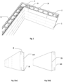
- Figure 1 shows an embodiment of the insulating concrete formwork system with insulating panels and connection elements that comprises: at least two panels (1,5); one or more connecting devices (2,7) for connection of the panels (1,5) so as to create/provide the space (6) to receive the fluid structuring material; at least two sections (3) to fit into the panels (1,5) interconnected by said connecting devices (2,7); wherein the panels (1,5) comprise a cavity (10) along the length in said panel (1,5) to fit one or more sections (3); wherein the sections (3) comprise a lateral flashing (11) with a plurality of holes (12) to fit the connecting devices (2,7); wherein the connecting devices (2,7) have a plurality of hooks (16) adapted to enter axially in the holes (12) of said sections (3).
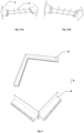
- the EPS for fabrication of the panels (1,5), as in figure 2 may be supplied in large blocks.
- the PVC for fabrication of sections (3), as in figure 3 may be supplied in sections already.
- the steel for fabrication of the connecting devices (2,7), as in figure 4 may be supplied in electrically welded sheets of raw steel.
- the panel (1,5), as in figure 2 may be fabricated from blocks supplied in large sizes with the help of a foam cutter, which may be a pantograph.
- a foam cutter which may be a pantograph.
- This is a peculiar characteristic in the fabrication of the panels of this publication, as it is the first solution to use the cutting system for fabrication of panels in insulating formwork systems.
- Various types of densities can be used in accordance with the type of mechanical resistance necessary for the formwork depending on the execution of the respective thicknesses of the constructions.
- the panels may comprise other types of polystyrene compounds, such as, EPS X, graphited polystyrene etc., in order to satisfy other needs, such as, greater impermeability, protection against UV rays or other specifics.
- Other types of foams can also be used that include the possibility of cutting in these kinds of machines and which provide the low thermal conductibility and mechanical resistance for the intended effect.
- the EPS panel was created, designed and developed specifically for this insulating formwork system, with no similar ones being available.
- the panel (1,5) has two faces, the outer face which comprises a plurality of marks on the vertical, preferably between 3 and 5 marks, facing out of the formwork, opposite to the inner face facing into the formwork.
- Said panel (1,5) also has four ends, an upper horizontal end, having a cavity along its length (10) and a lower horizontal end opposite the upper one which also has a cavity along its length (10) opposite the cavity of the upper end as in figure 2 .
- the upper horizontal end also comprises a recess (8) along its length, and the lower end comprises a protuberance (9) along its length as in figure 2 .
- the vertical left end opposite the right end comprises a recess and a protuberance along its height (15,14), and the vertical right side comprises a protuberance and a recess along its height (15,14) opposite the left end as in figure 2 .
- the panel (1,5) can be 1200mm in length.
- This length has the objective of having the same width as the plasterboard panels (Pladur), and it is imperative that the measures match so that the installation is easy and intuitive without having to make unnecessary cuts in the respective plasterboard.
- panels (1,5) the shorter lengths needed are cut using a saw or with a manual foam cutter when assembling the system in the execution of the work, thus enabling an infinite plurality of variants, making the system versatile and adaptable to any situation.
- the length is understood to be the distance that separates the left end from the right end.
- the minimum thickness of the panel (1,5) may be 63 mm so that the deepest electrical junction boxes can be placed without difficulties within this thickness and may be more than 200 mm, as in figure 13 , so as to make the formwork with greater thermal insulation that could be applied where the climate so demands.
- the thickness is understood to be the distance comprised between the outer face and the inner face of said panel (1,5).
- the height of the normal panel (1,5) may be 250 mm or 333 mm, with the latter being to execute constructions of smaller thicknesses where the need for mechanical resistance of the formwork is lower.
- the height is understood to be the distance comprised between the upper end and the lower end.
- the measures presented may vary, i.e. may be slightly altered so as to make better use of the raw material and with the reduction of product costs in the fabrication.
- the panels (1,5) comprise 3 marks painted vertically, represented by the broken line, located every 300mm, which serve as a reference for the placement of the connecting devices (2,7), for the correct positioning of the intercalating of the panels (1,5), and so that the electrician and the plumber know where the sections are placed (3), avoiding them when making the cuts to insert the respective tubing without loss of time.
- the plasterboard can be fixed/screwed to the sections (3) in a simple, intuitive and quick manner.
- the panel (1,5) comprises a recess along the length on the upper end which serves to house the lateral flashing of the section.
- the panels (1,5) also comprise a protuberance (9) along the length on the lower end, so as to make a filter, as in figure 12 , as when one panel is pressed on another, the extremity of said protuberance is pressed in the area of the wires, of the connecting devices (2,7), making a seal and impeding the passage of the concrete placed in the space (6) between the walls of the formwork for the areas of the recesses (8) of the panels (1,5) so as not to compromise the thermal insulation of the set.
- the sections (3) have a lateral flashing (11) with a plurality of holes (12) to fit the connecting devices (2,7).
- the panels (1,5) are adapted with the cavities (10) along the length of the upper end and along the length of the lower end in opposite manner for fitting the sections (3) together and interconnecting said panels (1,5) to each other in a superimposed and intercalated manner forming a wall of said formwork, which together with the hooks (16) of the extremities of said connecting devices (2,7), i.e. the ends of the rods/hooks (16), which pass through the holes (12), located in the lateral flashing (11) of the sections (3), thus interconnecting with another opposite wall and making up the formwork as shown in figure 1 .
- the recess (8) is also useful if the water penetrates with residues of concrete, so that these do not go up and enter the cavity (10) created to lodge the section (3). On the other hand, it also serves to allow said residues to be deposited and stay there, as shown in figure 12 , so as not to compromise the thermal insulation of the system.
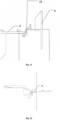
- a panel (1,5) is provided with a protuberance (14) at the height of the right end and a recess (15) at the height of the left end, vertically opposite close to the inner face of said panel (1,5), which when the panels (1,5) are joined contiguously, form a perfect fit so that the concrete does not leak from the wall of the formwork even if there is some slack in the joint, as shown in the lower part of figure 9 , and remains in the space (6) in contact with the inner faces of said panels (1,5).
- a panel (1,5) is provided with a protuberance and recess (14,15) at the height of the right end and a recess and protuberance (15,14), at the height of the left end, vertically opposite so that when the panels (1,5) are joined contiguously, they form a perfect fit so that the concrete does not leak to the wall of the formwork even if there is some slack in this joint.
- the section (3) fabricated in PVC is a section with unique characteristics as there is no other like it and it was designed specifically for this ICF solution.
- the PVC used in this embodiment may be stiffened to guarantee a mechanical resistance not just for the purposes of loading of the formwork, but also to be able to withstand significant loads it may be subjected to in the placement of the various elements referred to previously.
- a metallic material (13) is placed, preferably an aluminium band and/or paint, as illustrated in figure 3 , which allows the detection with a proximity "pinpointer" metal detector after the walls have been finished.
- the section (3) may be of 3 mm in thickness and in a format like a T lying down, where the "leg" makes an S-shape, i.e. a bend and a reverse bend, which is given the name of lateral flashing and which at its extremity may be of 4mm in thickness (the area where soon afterwards the holes will be made (12) ) for the placing of the connecting devices (2,7) so that its mechanical resistance is strengthened.
- each complete join (connecting devices (2,7) + section (3) ) due to the stiffened PVC and greater thickness referred to previously will have the particular characteristic of bearing a tension force (lateral) close to 200kg at a temperature of 20°C.
- the section (3) may be cut and drilled so that together with the connecting devices (2,7), as in figure 4 , the joints are formed as in figure 5 and which fitted into the cavities (10) of the panels (1,5) placed opposite in parallel, make up the formwork (ICF), as in figure 1 and 10 .
- the connecting devices (2,7) may be fabricated in electrically welded raw steel.
- the transversal metallic rods of about 100 mm shown in these connecting devices serve to maintain these and the system squaring, but also to be able to tie the structural iron rebar when assembling this insulating formwork system.
- the dimensions of these rods are merely indicative and are related to the cost and speed of fabrication. If during assembly and/or placement of the structural iron rebar the dimension of the beams referred to previously conditions the speed of execution, this measure will come to have the minimum and executable possible by the cutting and fabrication machines.
- the connecting devices (2,7) may be fabricated in electrically welded raw steel.
- the transversal metallic rods, i.e. perpendicular of about 100 mm shown in these connecting devices serve to maintain the wires in parallel and the squaring of these and of the system.
- the connecting devices (2,7) may have various measures on length which serve together with the section (3) to form the joint between the walls of the formwork, as shown in figure 5 . It is important to mention that it is the length of these connecting devices that defines the space in the interior of the formwork and consequently the thickness of the wall and/or construction.
- the fabrication of the connecting devices (2,7) is planned in various lengths as in figure 4 , so as to enable that the walls/constructions are approximately 10, 15, 20, 25, 30, 35 cm in thickness. These are the standard measures, and other measures may be made to order, whether for thicker walls, or for the execution of formwork for pillars of greater size with the use of ICF or another specific type of formwork for the works/construction in question.
- Another purpose of the connecting devices (2,7) is the support for and tying of the structural iron rebar helping in its placement and becoming part of the same.
- the complete join (connecting device with sections (3) opposite), with the sections (3) interconnected by the connecting devices that fit into the cavities (10) of the panels (1,5) which guarantee the safety of the system and all the elements can be screwed to these: Plasterboard, shelves, television screens, pictures, cupboards, phenolics and it will even be possible to place heavy coatings as each one of these joints will be able to bear weights close to 200kg.
- the sections (3) will also be able to have the plumb checks screwed to them when assembling the formwork, which guarantee the verticality of the system and the safety of the formwork until the concrete has dried. It should also be pointed out that when the door and window frames are done with formwork using the ends shown in figure 7 , we enable the possibility of fixing the windows and doors directly to the system with the maximum of safety and speed without having to make holes and/or to place bushes.
- the panels (1,5) can be placed superimposed and intercalated contiguously, where the vertical marks allow the placement of the joints with precision and the correct position for their intercalation. This makes everything much more intuitive in the assembly as well as in the placement of the plasterboard as at each crossing point between the lines and the extremity of the panel there will be a section (3) where the plasterboard can be screwed.
- Figure 8 shows the dotted lines of the vertical marks to facilitate the assembly of the formwork of the present embodiment. It is important to mention that this embodiment does not comprise the extremities of the panel (1,5) signalled, as indicated in figure 8 , and the marks will be coloured and thick, preferably from 2 to 3mm.
- the system can allow fixing points like no other system in the present state of the art. It is important to mention that after the finishing and painting, one can always find out where the sections (3) are by using a metal detector so that the supports for placement can be screwed, for example, for a picture or a television screen. It is important to mention that no system of this type of formwork allows this particular detail.
- the cavity is filled by the section (3), and the recess (8) of the upper end, houses the lateral flashing (11) together with the extremities of the hooks (16) of the connecting devices which also serve to house/deposit and solidify there in isolation, some residues of concrete which may pass to the interior of the recess, so as not to compromise the thermal insulation of the set.
- the non-standard panel (1,5) of 150mm in thickness serves as an example and is projected to be applied only on the side of the formwork corresponding to the exterior of the construction, adaptable to the local climate. For example, in very cold countries or just to satisfy more demanding clients who want greater thermal insulation.
Landscapes
- Engineering & Computer Science (AREA)
- Architecture (AREA)
- Physics & Mathematics (AREA)
- Electromagnetism (AREA)
- Civil Engineering (AREA)
- Structural Engineering (AREA)
- Forms Removed On Construction Sites Or Auxiliary Members Thereof (AREA)
Claims (15)
- Isolierendes Betonschalungssystem mit Isolierplatten (1,5) und Verbindungselementen, umfassend:zwei oder mehr Isolierplatten (1,5) zur Aufnahme eines flüssigen, strukturgebenden Betonmaterials zwischen den genannten Platten (1,5);mindestens zwei Profile (3), die jeweils in eine der genannten Platten (1,5) passen;eine oder mehrere Verbindungsvorrichtungen (2,7), umfassend zwei Enden, von denen jedes mit einem Abschnitt verbunden werden kann, um zwei Platten (1,5) zu verbinden;wobei jede Platte (1,5) vier Enden hat, einschließlich eines oberen Endes und ein dem oberen Ende gegenüberliegendes unteres Ende;wobei die Platten (1,5) einen Hohlraum (10) zur Aufnahme eines oder mehrerer Profile (3) entlang des oberen Endes jeder Platte (1,5) umfassen;wobei die Platten (1,5) einen Hohlraum (10) zur Aufnahme eines oder mehrerer Profile (3) entlang des unteren Endes jeder Platte (1,5) umfassen;wobei die Profile (3) ein seitliches Element (11) mit einer Vielzahl von Löchern (12) umfassen, um die Enden der Verbindungsvorrichtungen (2,7) zu befestigen;wobei die Verbindungsvorrichtungen (2,7) an ihren beiden Enden eine Vielzahl von Haken (16) umfassen, die in die genannten Löcher (12) des jeweiligen Profils (3) eingreifen;dadurch gekennzeichnet, dass die Platten (1,5) entlang der Länge des unteren Endes einen Vorsprung (9) und entlang der Länge des oberen Endes eine Aussparung (8) zum Übereinanderlegen der Platten (1,5) umfassen;wobei der Vorsprung (9) oder die Aussparung (8) so ausgelegt sind, dass sie zusammen mit den Haken (16) der genannten Verbindungsvorrichtung (2, 7) in die seitlichen Elemente (11) der genannten Profile (3) passen;und die Aussparung (8) so angeordnet ist, dass sich darin Rückstände ablagern können.
- Isolierendes Betonschalungssystem nach dem vorangehenden Anspruch, wobei die Verbindungsvorrichtungen (2,7) mindestens zwei längsparallele Metallstangen umfassen, um jedes ihrer Enden mit dem entsprechenden Profil (3) zu verbinden.
- Isolierendes Betonschalungssystem nach einem der vorangehenden Ansprüche, wobei die genannten Haken (16) L-förmig mit 90° sind.
- Isolierendes Betonschalungssystem nach dem vorangehenden Anspruch, wobei die genannten Haken (16) gekrümmte und umgekehrt gekrümmte Enden aufweisen.
- Isolierendes Betonschalungssystem nach einem der vorangehenden Ansprüche, wobei jede Isolierplatte (1,5) ein linkes Ende und ein rechtes Ende umfasst, mit Aussparungen und Vorsprüngen (15,14) an jedem der genannten Enden, um mit einem rechten Ende an einer anderen Platte bzw. einem linken Ende an einer anderen Platte (1,5) fortlaufend abzuschließen.
- Isolierendes Betonschalungssystem nach Anspruch 2 und einem der Ansprüche 3-4, wobei die Verbindungsvorrichtungen (2,7) eine Vielzahl von quer verlaufenden Metallstäben umfassen, um die in genannten längsparallelen Metallstäbe miteinander zu verbinden.
- Isolierendes Betonschalungssystem nach einem der vorangehenden Ansprüche, wobei die Platten (1,5) eine Vielzahl von Farbmarkierungen, bevorzugt 3 bis 5 Markierungen aufweisen, die vertikal auf der Außenseite der Platte (1,5) angeordnet sind, um die Stelle für die Befestigung der genannten Abschnitte und die Positionierung der Platten (1,5) festzulegen, bevorzugt mit einem Abstand von 100 bis 350 mm zwischen den genannten Markierungen.
- Isolierendes Betonschalungssystem nach dem vorangehenden Anspruch, wobei der Vorsprung am unteren Ende der Platte so ausgebildet ist, dass er mit dem oberen Ende einer anderen Platte abschließt und durch Herunterdrücken des Endes des Vorsprungs der genannten Platte im Bereich der Verbindungsvorrichtung eine Dichtung bildet, so dass der Beton innerhalb der Schalung bleibt und nicht in den Bereich der Aussparung des oberen Endes der genannten Platte (1,5) austritt.
- Isolierendes Betonschalungssystem nach einem der vorangehenden Ansprüche, wobei die Abschnitte ein Material umfassen, das teilweise aus Metall, bevorzugt aus einem Aluminiumband hergestellt ist.
- Isolierendes Betonschalungssystem nach einem der vorangehenden Ansprüche, wobei die Länge der Platten (1,5) zwischen 100 - 1300 mm, insbesondere zwischen 1100 - 1300 mm variiert.
- Isolierendes Betonschalungssystem nach einem der vorangehenden Ansprüche, wobei die Höhe der Platten (1,5) zwischen 240 - 350 mm variiert.
- Isolierendes Betonschalungssystem nach einem der vorangehenden Ansprüche, wobei die Verbindungsvorrichtung (2,7) aus elektrisch geschweißtem Rohstahl ist.
- Wand, Pfeiler oder jede andere Art von Konstruktion, die ein isolierendes Betonschalungssystem nach einem der vorangehenden Ansprüche umfasst.
- Isolierendes Betonschalungssystem mit Isolierplatten (1,5) nach Anspruch 1, wobei jede der genannten Isolierplatte (1,5) eine Platte für den Zusammenbau eines isolierenden Betonschalungssystems ist, umfassend:vier Enden, darunter ein oberes Ende und ein dem oberen Ende gegenüberliegendes unteres Ende, ein vertikales rechtes Ende und ein vertikales linkes Ende,wobei das obere Ende eine vorstehende Kante entlang der Länge der Platte, eine Aussparung entlang der Länge der Platte und einen Hohlraum umfasst, der in der genannten Aussparung entlang der Länge der Platte angeordnet ist;wobei das untere Ende eine vorstehende Kante entlang der Länge der Platte umfasst, die in einer Trichterform endet, um die Verbindungsstangen aus Metall zusammenzudrücken, wenn sie auf eine andere Platte aufgesetzt werden.
- Verfahren für den Zusammenbau des isolierenden Betonschalungssystems mit Isolierplatten (1,5) und Verbindungselementen nach einem der Ansprüche 1-12, umfassend: mindestens zwei Platten (1,5); mindestens zwei Profile (3); eine oder mehrere Verbindungsvorrichtungen (2,7); wobei das Verfahren die folgenden Schritte umfasst:Anordnen von mindestens zwei parallel zueinander gegenüberliegenden Platten, um einen Raum zwischen den Platten zur Aufnahme des genannten flüssigen, strukturgebenden Betonmaterials zu bilden;Einbringen der Abschnitte in die Hohlräume der genannten Platten;Anbringen der Verbindungselemente in den genannten Profilen, um die entsprechenden Platten miteinander zu verbinden;Wiederholen der Montage des Systems, so dass die Platten aneinandergrenzend und übereinanderliegend montiert werden;Füllen des Raums zwischen den beiden Platten mit dem flüssigen, strukturgebenden Material.
Applications Claiming Priority (2)
| Application Number | Priority Date | Filing Date | Title |
|---|---|---|---|
| PT11585919 | 2019-10-23 | ||
| PCT/IB2020/059991 WO2021079342A1 (pt) | 2019-10-23 | 2020-10-23 | Sistema de cofragens de betão com paineis isolantes, elementos de ligação e método de montagem |
Publications (3)
| Publication Number | Publication Date |
|---|---|
| EP4050174A1 EP4050174A1 (de) | 2022-08-31 |
| EP4050174B1 true EP4050174B1 (de) | 2024-12-04 |
| EP4050174C0 EP4050174C0 (de) | 2024-12-04 |
Family
ID=74130285
Family Applications (1)
| Application Number | Title | Priority Date | Filing Date |
|---|---|---|---|
| EP20838285.3A Active EP4050174B1 (de) | 2019-10-23 | 2020-10-23 | Betonschalungssystem mit isolierplatten, verbindungselementen und montageverfahren |
Country Status (3)
| Country | Link |
|---|---|
| US (1) | US20220364360A1 (de) |
| EP (1) | EP4050174B1 (de) |
| WO (1) | WO2021079342A1 (de) |
Families Citing this family (1)
| Publication number | Priority date | Publication date | Assignee | Title |
|---|---|---|---|---|
| CN118564042A (zh) * | 2024-06-21 | 2024-08-30 | 海南兴晟嘉科技贸易有限公司 | 一种拼接式免拆墙体模板结构、连结件及装配方法 |
Family Cites Families (26)
| Publication number | Priority date | Publication date | Assignee | Title |
|---|---|---|---|---|
| GB1169723A (en) * | 1966-03-22 | 1969-11-05 | Roher Bohm Ltd | Form for Cementitious Material |
| US3562991A (en) * | 1968-07-29 | 1971-02-16 | Paul W Kustusch | Building wall construction and module therefor |
| US4336676A (en) * | 1977-12-05 | 1982-06-29 | Covington Brothers, Inc. | Composite structural panel with offset core |
| US4433520A (en) * | 1980-12-15 | 1984-02-28 | Jack Maschhoff | Building wall construction |
| US4574550A (en) * | 1984-05-21 | 1986-03-11 | Jack Maschhoff | Building wall and insulation assembly |
| IL75758A (en) * | 1985-07-10 | 1988-02-29 | Snitovski Jacov | Thermally-insulating masonry block,method for manufacturing such a block and method of building a wall of such blocks |
| US4750308A (en) * | 1987-02-09 | 1988-06-14 | Mckay Harry | Heat resistant, insulated wall construction |
| FR2647839B1 (fr) * | 1989-05-31 | 1991-09-20 | Durand Philippe | Elements prefabriques de coffrage et procede de construction de murs |
| US5248122A (en) * | 1989-06-22 | 1993-09-28 | Graham Tom S | Pre-attached form system for insulated concrete wall panel |
| FR2754285A1 (fr) * | 1996-10-03 | 1998-04-10 | Ktbat | Element de coffrage isolant pour mur en beton |
| US6279285B1 (en) * | 1999-01-18 | 2001-08-28 | K-Wall Poured Walls, Inc. | Insulated concrete wall system |
| HRP20040578B1 (hr) | 2004-06-21 | 2012-11-30 | Pjer-Miše Veličković | Varijabilne spone za povezivanje oplate od izo-ploäśa visoke nosivosti, ispune i izo-ispune visoke nosivosti za postavljanje a/b ploäśe |
| ITTO20050349A1 (it) * | 2005-05-20 | 2006-11-21 | Nuova Ceval S R L | Dispositivo di vincolo per pannelli di prefabbricazione edilizia |
| KR100947057B1 (ko) * | 2007-12-12 | 2010-03-11 | 김규희 | 건축용 블록 |
| PT104019B (pt) | 2008-04-14 | 2010-07-05 | Antenio Vieira Fernandes De Lima | Bloco para cofragem perdida com isolamento e ligaã†o rebat�vel e dispositivo conector. |
| US7874112B2 (en) * | 2008-06-20 | 2011-01-25 | Nova Chemicals Inc. | Footer cleat for insulating concrete form |
| US9091055B2 (en) * | 2008-08-19 | 2015-07-28 | Sonoma Cast Stone Corporation | Wall assembly method |
| EP2410101B1 (de) * | 2010-07-22 | 2015-04-29 | Euromac 2 (Societe A Responsabilite Limitee) | Isolierende Blockschalung |
| CA2793668A1 (en) * | 2011-10-31 | 2013-04-30 | Bradley J. Crosby | An apparatus and method for construction of structures utilizing insulated concrete forms |
| USD713975S1 (en) * | 2012-07-30 | 2014-09-23 | Airlite Plastics Co. | Insulative insert for insulated concrete form |
| US9234347B2 (en) * | 2013-02-04 | 2016-01-12 | Andŕe Cossette | Crossed ties for construction block assembly |
| US9151051B2 (en) * | 2013-02-04 | 2015-10-06 | Andre Cossette | 65 db sound barrier insulated block |
| US9447578B2 (en) * | 2015-01-02 | 2016-09-20 | Richard Nelson DeBoer | Modular block wall system |
| FR3047501B1 (fr) * | 2016-02-09 | 2021-04-02 | G2S Tech S A | Bloc de construction isole entre planelles avec structure de maintien des planelles. |
| US11015345B1 (en) * | 2020-01-18 | 2021-05-25 | Walter Smith | Concrete wall section |
| US11718985B2 (en) * | 2020-10-14 | 2023-08-08 | Isaac Walker | Construction block |
-
2020
- 2020-10-23 WO PCT/IB2020/059991 patent/WO2021079342A1/pt not_active Ceased
- 2020-10-23 US US17/771,057 patent/US20220364360A1/en not_active Abandoned
- 2020-10-23 EP EP20838285.3A patent/EP4050174B1/de active Active
Also Published As
| Publication number | Publication date |
|---|---|
| EP4050174A1 (de) | 2022-08-31 |
| US20220364360A1 (en) | 2022-11-17 |
| EP4050174C0 (de) | 2024-12-04 |
| WO2021079342A1 (pt) | 2021-04-29 |
Similar Documents
| Publication | Publication Date | Title |
|---|---|---|
| CN100523398C (zh) | 建筑模板 | |
| EP0694102B1 (de) | Gussbetonwände | |
| US6729094B1 (en) | Pre-fabricated building panels and method of manufacturing | |
| CA2502343C (en) | Concrete fillable formwork wall | |
| US6167671B1 (en) | Prefabricated concrete wall form system | |
| US6880304B1 (en) | Structural thermal framing and panel system for assembling finished or unfinished walls with multiple panel combinations for poured and nonpoured walls | |
| US3683569A (en) | Structural connections for building constructions | |
| US20170121967A1 (en) | Concrete Panel and Concrete Panel Connector Structure for Forming Reinforced Concrete Building Components | |
| US9157234B1 (en) | Free-standing form for building a pre-insulated wall | |
| US4676035A (en) | Reinforced concrete panels with improved welded joint | |
| EP3610091B1 (de) | Verriegelbarer baustein | |
| US20050050838A1 (en) | Building component | |
| US6293068B1 (en) | Foam panel and channel concrete form system | |
| EP4050174B1 (de) | Betonschalungssystem mit isolierplatten, verbindungselementen und montageverfahren | |
| AU2011287189B2 (en) | System of disposable moulds used to make-up modular formworks to build-up concrete walls featuring complex shapes | |
| US20160032594A1 (en) | Building panels and building system using such panels | |
| ZA200901736B (en) | Improved construction system for buildings | |
| ES3008024T3 (en) | Concrete formwork system with insulating panels, connection elements and assembly method | |
| GB2560812A (en) | Improved insulated building section | |
| EP2639372B1 (de) | Wandkonstruktion und Herstellungsmethode | |
| CN206070791U (zh) | 基于带安装槽条形保温墙板组装的框架剪力墙结构 | |
| CN205907850U (zh) | 基于带安装槽条形保温墙板组装的剪力墙结构 | |
| NZ585862A (en) | Hollow wall construction using panel joining profiles that are connected together by spacers | |
| CN106401008A (zh) | 基于带安装槽条形保温墙板组装的剪力墙结构及其建造方法 | |
| DE825890C (de) | Bauwerk aus tafelfoermigen Bauelementen |
Legal Events
| Date | Code | Title | Description |
|---|---|---|---|
| STAA | Information on the status of an ep patent application or granted ep patent |
Free format text: STATUS: UNKNOWN |
|
| STAA | Information on the status of an ep patent application or granted ep patent |
Free format text: STATUS: THE INTERNATIONAL PUBLICATION HAS BEEN MADE |
|
| PUAI | Public reference made under article 153(3) epc to a published international application that has entered the european phase |
Free format text: ORIGINAL CODE: 0009012 |
|
| STAA | Information on the status of an ep patent application or granted ep patent |
Free format text: STATUS: REQUEST FOR EXAMINATION WAS MADE |
|
| 17P | Request for examination filed |
Effective date: 20220505 |
|
| AK | Designated contracting states |
Kind code of ref document: A1 Designated state(s): AL AT BE BG CH CY CZ DE DK EE ES FI FR GB GR HR HU IE IS IT LI LT LU LV MC MK MT NL NO PL PT RO RS SE SI SK SM TR |
|
| DAV | Request for validation of the european patent (deleted) | ||
| DAX | Request for extension of the european patent (deleted) | ||
| STAA | Information on the status of an ep patent application or granted ep patent |
Free format text: STATUS: EXAMINATION IS IN PROGRESS |
|
| 17Q | First examination report despatched |
Effective date: 20240118 |
|
| GRAP | Despatch of communication of intention to grant a patent |
Free format text: ORIGINAL CODE: EPIDOSNIGR1 |
|
| STAA | Information on the status of an ep patent application or granted ep patent |
Free format text: STATUS: GRANT OF PATENT IS INTENDED |
|
| INTG | Intention to grant announced |
Effective date: 20240628 |
|
| GRAS | Grant fee paid |
Free format text: ORIGINAL CODE: EPIDOSNIGR3 |
|
| GRAA | (expected) grant |
Free format text: ORIGINAL CODE: 0009210 |
|
| STAA | Information on the status of an ep patent application or granted ep patent |
Free format text: STATUS: THE PATENT HAS BEEN GRANTED |
|
| AK | Designated contracting states |
Kind code of ref document: B1 Designated state(s): AL AT BE BG CH CY CZ DE DK EE ES FI FR GB GR HR HU IE IS IT LI LT LU LV MC MK MT NL NO PL PT RO RS SE SI SK SM TR |
|
| REG | Reference to a national code |
Ref country code: CH Ref legal event code: EP |
|
| REG | Reference to a national code |
Ref country code: DE Ref legal event code: R096 Ref document number: 602020042672 Country of ref document: DE |
|
| REG | Reference to a national code |
Ref country code: IE Ref legal event code: FG4D |
|
| U01 | Request for unitary effect filed |
Effective date: 20250103 |
|
| U07 | Unitary effect registered |
Designated state(s): AT BE BG DE DK EE FI FR IT LT LU LV MT NL PT RO SE SI Effective date: 20250116 |
|
| REG | Reference to a national code |
Ref country code: ES Ref legal event code: FG2A Ref document number: 3008024 Country of ref document: ES Kind code of ref document: T3 Effective date: 20250321 |
|
| PG25 | Lapsed in a contracting state [announced via postgrant information from national office to epo] |
Ref country code: HR Free format text: LAPSE BECAUSE OF FAILURE TO SUBMIT A TRANSLATION OF THE DESCRIPTION OR TO PAY THE FEE WITHIN THE PRESCRIBED TIME-LIMIT Effective date: 20241204 |
|
| PG25 | Lapsed in a contracting state [announced via postgrant information from national office to epo] |
Ref country code: NO Free format text: LAPSE BECAUSE OF FAILURE TO SUBMIT A TRANSLATION OF THE DESCRIPTION OR TO PAY THE FEE WITHIN THE PRESCRIBED TIME-LIMIT Effective date: 20250304 |
|
| PG25 | Lapsed in a contracting state [announced via postgrant information from national office to epo] |
Ref country code: GR Free format text: LAPSE BECAUSE OF FAILURE TO SUBMIT A TRANSLATION OF THE DESCRIPTION OR TO PAY THE FEE WITHIN THE PRESCRIBED TIME-LIMIT Effective date: 20250305 |
|
| PG25 | Lapsed in a contracting state [announced via postgrant information from national office to epo] |
Ref country code: RS Free format text: LAPSE BECAUSE OF FAILURE TO SUBMIT A TRANSLATION OF THE DESCRIPTION OR TO PAY THE FEE WITHIN THE PRESCRIBED TIME-LIMIT Effective date: 20250304 |
|
| PG25 | Lapsed in a contracting state [announced via postgrant information from national office to epo] |
Ref country code: SM Free format text: LAPSE BECAUSE OF FAILURE TO SUBMIT A TRANSLATION OF THE DESCRIPTION OR TO PAY THE FEE WITHIN THE PRESCRIBED TIME-LIMIT Effective date: 20241204 |
|
| PG25 | Lapsed in a contracting state [announced via postgrant information from national office to epo] |
Ref country code: PL Free format text: LAPSE BECAUSE OF FAILURE TO SUBMIT A TRANSLATION OF THE DESCRIPTION OR TO PAY THE FEE WITHIN THE PRESCRIBED TIME-LIMIT Effective date: 20241204 |
|
| PG25 | Lapsed in a contracting state [announced via postgrant information from national office to epo] |
Ref country code: IS Free format text: LAPSE BECAUSE OF FAILURE TO SUBMIT A TRANSLATION OF THE DESCRIPTION OR TO PAY THE FEE WITHIN THE PRESCRIBED TIME-LIMIT Effective date: 20250404 |
|
| PG25 | Lapsed in a contracting state [announced via postgrant information from national office to epo] |
Ref country code: SK Free format text: LAPSE BECAUSE OF FAILURE TO SUBMIT A TRANSLATION OF THE DESCRIPTION OR TO PAY THE FEE WITHIN THE PRESCRIBED TIME-LIMIT Effective date: 20241204 |
|
| PG25 | Lapsed in a contracting state [announced via postgrant information from national office to epo] |
Ref country code: CZ Free format text: LAPSE BECAUSE OF FAILURE TO SUBMIT A TRANSLATION OF THE DESCRIPTION OR TO PAY THE FEE WITHIN THE PRESCRIBED TIME-LIMIT Effective date: 20241204 |
|
| PLBE | No opposition filed within time limit |
Free format text: ORIGINAL CODE: 0009261 |
|
| STAA | Information on the status of an ep patent application or granted ep patent |
Free format text: STATUS: NO OPPOSITION FILED WITHIN TIME LIMIT |
|
| 26N | No opposition filed |
Effective date: 20250905 |
|
| U20 | Renewal fee for the european patent with unitary effect paid |
Year of fee payment: 6 Effective date: 20251021 |
|
| PGFP | Annual fee paid to national office [announced via postgrant information from national office to epo] |
Ref country code: ES Payment date: 20251118 Year of fee payment: 6 |