EP4049805A1 - Workpiece photograph image processing device, workpiece photograph image processing method, and machining system - Google Patents
Workpiece photograph image processing device, workpiece photograph image processing method, and machining system Download PDFInfo
- Publication number
- EP4049805A1 EP4049805A1 EP20879458.6A EP20879458A EP4049805A1 EP 4049805 A1 EP4049805 A1 EP 4049805A1 EP 20879458 A EP20879458 A EP 20879458A EP 4049805 A1 EP4049805 A1 EP 4049805A1
- Authority
- EP
- European Patent Office
- Prior art keywords
- photographed image
- workpiece
- image
- photographed
- camera
- Prior art date
- Legal status (The legal status is an assumption and is not a legal conclusion. Google has not performed a legal analysis and makes no representation as to the accuracy of the status listed.)
- Granted
Links
Images




Classifications
-
- G—PHYSICS
- G06—COMPUTING OR CALCULATING; COUNTING
- G06T—IMAGE DATA PROCESSING OR GENERATION, IN GENERAL
- G06T5/00—Image enhancement or restoration
- G06T5/80—Geometric correction
-
- B—PERFORMING OPERATIONS; TRANSPORTING
- B25—HAND TOOLS; PORTABLE POWER-DRIVEN TOOLS; MANIPULATORS
- B25J—MANIPULATORS; CHAMBERS PROVIDED WITH MANIPULATION DEVICES
- B25J13/00—Controls for manipulators
- B25J13/08—Controls for manipulators by means of sensing devices, e.g. viewing or touching devices
-
- B—PERFORMING OPERATIONS; TRANSPORTING
- B25—HAND TOOLS; PORTABLE POWER-DRIVEN TOOLS; MANIPULATORS
- B25J—MANIPULATORS; CHAMBERS PROVIDED WITH MANIPULATION DEVICES
- B25J9/00—Program-controlled manipulators
- B25J9/16—Program controls
- B25J9/1694—Program controls characterised by use of sensors other than normal servo-feedback from position, speed or acceleration sensors, perception control, multi-sensor controlled systems, sensor fusion
- B25J9/1697—Vision controlled systems
-
- G—PHYSICS
- G06—COMPUTING OR CALCULATING; COUNTING
- G06T—IMAGE DATA PROCESSING OR GENERATION, IN GENERAL
- G06T7/00—Image analysis
- G06T7/70—Determining position or orientation of objects or cameras
- G06T7/73—Determining position or orientation of objects or cameras using feature-based methods
-
- G—PHYSICS
- G06—COMPUTING OR CALCULATING; COUNTING
- G06T—IMAGE DATA PROCESSING OR GENERATION, IN GENERAL
- G06T2207/00—Indexing scheme for image analysis or image enhancement
- G06T2207/30—Subject of image; Context of image processing
- G06T2207/30108—Industrial image inspection
- G06T2207/30164—Workpiece; Machine component
-
- G—PHYSICS
- G06—COMPUTING OR CALCULATING; COUNTING
- G06T—IMAGE DATA PROCESSING OR GENERATION, IN GENERAL
- G06T2207/00—Indexing scheme for image analysis or image enhancement
- G06T2207/30—Subject of image; Context of image processing
- G06T2207/30204—Marker
-
- G—PHYSICS
- G06—COMPUTING OR CALCULATING; COUNTING
- G06T—IMAGE DATA PROCESSING OR GENERATION, IN GENERAL
- G06T2207/00—Indexing scheme for image analysis or image enhancement
- G06T2207/30—Subject of image; Context of image processing
- G06T2207/30204—Marker
- G06T2207/30208—Marker matrix
Definitions
- the present disclosure relates to a workpiece photographed image processing device, a workpiece photographed image processing method, and a processing system.
- a workpiece retention robot may retain a workpiece placed at a placement location such as a pallet and transport the workpiece to a processing machine such as a press brake (see Patent Literature 1).
- An image processing device detects, based on a photographed image photographed by a camera, the position of the workpiece of the workpiece placed at the placement location.
- Patent Literature 1 Japanese Patent Application Laid-Open Publication No. 2018-120388
- the workpiece needs to be photographed by the camera from directly above the workpiece so that the shape of the workpiece is properly photographed.
- the camera if the camera is located directly above the workpiece, the workpiece, a crane, or a workpiece retention robot may interfere with the camera when the crane places the workpiece to the placement location or the workpiece retention robot transports the workpiece. For this reason, it is necessary to retract the camera. Therefore, interference can be avoided if the camera is located at a position away from the workpiece retention robot deviated from directly above the center of the placement location.
- the camera is located at a position deviated from the center of the placement location, the workpiece is photographed from an oblique direction.
- the shape of the workpiece is not properly photographed.
- the workpiece is rectangular, the workpiece is be photographed in a trapezoidal shape. If the photographed workpiece does not properly represent the shape of the workpiece, the position of the workpiece placed at the placement location cannot be correctly recognized, and the workpiece retention robot may not be able to retain the workpiece. Therefore, it is necessary to correct, to an appropriate shape, the workpiece photographed image obtained by photographing the workpiece with a camera located at a position deviated from directly above the center of the placement location.
- a workpiece photographed image processing device that includes a first conversion parameter calculation unit configured to calculate, based on a first photographed image obtained by photographing a lattice pattern with a camera located at a position deviated from directly above a center of a placement location of a workpiece, a first conversion parameter for correcting an image distortion due to a lens of the camera, a lens distortion correction unit configured to correct, by using the first conversion parameter, the image distortion due to the lens included in a second photographed image obtained by photographing a jig board with the camera, a second conversion parameter calculation unit configured to extract a plurality of first reference points of the jig board within the second photographed image in which the image distortion is corrected by the lens distortion correction unit, and to calculate, based on the actual first reference points of the jig board and the extracted first reference points within the second photographed image, a second parameter for converting two-dimensional coordinates within a three-dimensional space photographed by the camera into positions of pixels within the
- a workpiece photographed image processing method includes calculating, based on a first photographed image obtained by photographing a lattice pattern with a camera located at a position deviated from directly above a center of a placement location of a workpiece, a first conversion parameter for correcting an image distortion due to a lens of the camera, correcting, by using the first conversion parameter, the image distortion due to the lens included in a second photographed image obtained by photographing a jig board with the camera, extracting a plurality of first reference points of the jig board within the second photographed image in which the image distortion is corrected, calculating, based on the actual first reference points of the jig board and the extracted first reference points within the second photographed image, a second parameter for converting two-dimensional coordinates within a three-dimensional space photographed by the camera into positions of pixels within the second photographed image, extracting, by using the second parameter, a region corresponding to an actual predetermined region of the jig board
- a processing system includes a camera located at a position deviated from directly above a center of a placement location of a workpiece, an image processing device configured to specify, by using a preliminarily determined conversion parameter, to which pixels in a photographed image two-dimensional coordinates within a photographed three-dimensional space correspond when the photographed image is generated by photographing, with the camera, the placement location at which the workpiece is placed, to align the specified pixels corresponding to the respective coordinates in a two-dimensional manner, and to generate a corrected photographed image in which a trapezoidal distortion in the photographed image is corrected, and a robot control device configured to detect a position of the workpiece at the placement location based on the corrected photographed image, and to control a workpiece retention robot so as to retain the workpiece and transport the workpiece to a processing machine.
- the workpiece photographed image processing device and the workpiece photographed image processing method of the one or more embodiments it is possible to correct the trapezoidal distortion in the workpiece photographed image obtained by photographing the workpiece with the camera located at the position deviated from directly above the center of the placement location.
- the processing system of the one or more embodiments it is possible to retain the workpiece by detecting the position of the workpiece based on the workpiece photographed image in which the trapezoidal distortion is corrected.
- FIG. 1 workpieces W are placed on a pallet 20, which is an example of a placement location.
- a plurality of workpieces W are loaded on the pallet 20.
- Frames 21a and 21b are arranged on both sides of the pallet 20.
- the frame 21a includes one vertical frame and a horizontal frame connected to the upper end portion of the vertical frame.
- the frame 21b includes a pair of vertical frames and a horizontal frame connected to the upper end portions of the pair of vertical frames.
- Lighting fixtures 22a and 22b are attached to the opposing surfaces of the horizontal frames of the frames 21a and 21b, respectively.
- the lighting fixtures 22a and 22b include, for example, a plurality of light emitting diodes (LEDs).
- the lighting fixtures 22a and 22b irradiate the workpiece W placed on the pallet 20 with illumination beams.
- An L-shaped support column 23 including a vertical frame extending to a predetermined height and a horizontal frame connected to the upper end portion of the vertical frame is attached to the frame 21a.
- a camera 30 is attached to the distal end of the support column 23 (the horizontal frame).
- the camera 30 is a so-called monocular camera.
- the camera 30 is located at a position deviated from directly above the center of the pallet 20 in a direction away from a workpiece retention robot 10 so as to photograph the pallet 20 and the workpiece W. In other words, the camera 30 photographs the pallet 20 and the workpiece W from an obliquely upper position. As a result, the camera 30 does not interfere with the operation of the workpiece retention robot 10 to retain and transport the workpiece W placed on the pallet 20.
- the workpiece W is irradiated with the illumination beams by the lighting fixtures 22a and 22b when the camera 30 photographs the workpiece W placed on the pallet 20.
- the edge of the workpiece W is clarified. This makes it easier to detect the position of the workpiece W when the position of the workpiece W is detected by pattern matching.
- the articulated workpiece retention robot 10 is arranged between the pallet 20 and a press brake 40, which is an example of the processing machine.
- the workpiece retention robot 10 includes a gripper 11 at the distal end thereof for sucking the workpiece W.
- the gripper 11 includes a plurality of suction pads 12. The gripper 11 sucks and retains one uppermost workpiece W, which is transported to the press brake 40 so that the workpiece is processed.
- photographed image data generated by the camera 30 is supplied to an image processing device 300.
- the image processing device 300 functions as a workpiece photographed image processing device of one or more embodiments. As described above, the camera 30 is located at the position deviated from directly above the center of the pallet 20 and photographs the workpiece W from the oblique direction. Therefore, the photographed image of the workpiece W is distorted in shape.
- the image processing device 300 corrects the photographed image into an appropriate shape, as will be described later.
- the image processing device 300 detects the position of the workpiece W based on the corrected photographed image, and supplies the detected position information to the robot control device 100.
- the robot control device 100 controls the workpiece retention robot 10 so as to retain the workpiece W on the pallet 20 based on the position information of the workpiece W.
- the image processing device 300 and the robot control device 100 can be configured with a computer device. By allowing the robot control device 100 to have the function of the image processing device 300, the robot control device 100 and the image processing device 300 may be integrated.
- the image processing device 300 executes processing shown in the flowchart of Figure 3 to correct the photographed image.
- step S1 the image processing device 300 corrects a distortion vector of a lens of the camera 30.
- step S2 the image processing device 300 photographs a jig board for calibration, and executes temporary calibration in step S3.
- step S4 the image processing device 300 extracts images of the positions of holes of the jig board, and obtains intersections between straight lines along the holes of the jig board in step S5.
- step S6 the image processing device 300 executes the actual calibration. As will be described later, by the processing of steps S1 to S6, conversion parameters are generated for generating a two-dimensional image in which a trapezoidal distortion photographed by the camera 30 is corrected.
- the image processing device 300 When the camera 30 photographs the pallet 20 in order to detect the position of the workpiece W placed on the pallet 20, in step S7, the image processing device 300 generates the two-dimensional image in which the trapezoidal distortion is corrected and supplies the detected position information of the workpiece W to the robot control device 100.
- FIG. 4 shows specific processing of step S1.
- the camera 30 photographs a chess board 50 as shown in Figure 5 .
- the chess board 50 is an example of a lattice pattern, but any graphic pattern may be used.
- a chess board photographed image 50i (a first photographed image) as shown in Figure 6 is obtained.
- the chess board photographed image 50i is input to the image processing device 300.
- the image processing device 300 detects grid points of the chess board photographed image 50i in step S12.
- the camera 30 photographs the chess board 50 a plurality of times in step S11 and supplies a plurality of the chess board photographed images 50i to the image processing device 300.
- the camera 30 may photograph the chess board 50 at a plurality of angles.
- the chess board 50 may be photographed such that the chess board photographed image 50i is not distorted into a trapezoidal shape.
- the chess board 50 may be photographed such that the chess board photographed image 50i is distorted into a trapezoidal shape.
- the image processing device 300 detects grid points of the respective chess board photographed images 50i, averages the grid points of the respective chess board photographed images 50i, and detects the grid points of the chess board photographed image 50i.
- the chess board photographed image 50i is distorted as compared with the chess board 50 due to distortion aberration and the like of the lens of the camera 30.
- the image processing device 300 calculates a first conversion parameter for correcting the distortion due to the lens. Since the expression for calculating the first conversion parameter is known, the details of the expression for calculating the first conversion parameter will be omitted.
- FIG. 7 shows specific processing of step S2.
- the robot control device 100 sucks a jig board 60 as shown in Figure 8 with the workpiece retention robot 10.
- the robot control device 100 displaces the jig board 60 above the pallet 20 a plurality of times in the horizontal direction and the vertical direction, and the camera 30 photographs the jig board 60 at each position.
- the jig board 60 is made of a sheet metal. As shown in Figure 8 , on the jig board 60, a plurality of groove-shaped openings 61 parallel to the longitudinal direction and a plurality of groove-shaped openings 62 parallel to the lateral direction, which is the width direction, are formed. The two openings 62 are arranged at both end portions of each of the openings 61 at a predetermined distance from the opening 61. The direction of the opening 61 and the direction of the opening 62 are orthogonal to each other. An AR marker 63 is provided on the side of the opening 61 between the two openings 62. As an example, the AR marker 63 is provided by attaching a sticker of the AR marker to the sheet metal and fixing the sheet metal to the jig board 60 by way of screwing or the like. The AR marker is an example of a marker.
- the width of the jig board 60 is 500 mm.
- the robot control device 100 displaces the jig board 60 by 300 mm in the horizontal direction after the camera 30 photographs the jig board 60.
- the robot control device 100 controls the workpiece retention robot 10 so as to displace the jig board 60 in the horizontal direction eight times from the position at which the jig board 60 is first placed, for example.
- the robot control device 100 displaces the jig board 60 in a direction connecting the lighting fixtures 22a and 22b in Figure 1 .
- the robot control device 100 displaces the jig board 60 in the vertical direction nine times, for example, at each horizontal position.
- the camera 30 photographs the jig board 60 at each horizontal and vertical position.
- the camera 30 photographs the jig board 60 at different positions in the horizontal or vertical position 90 times, and the photographed image data of the jig board 60 at each position is input to the image processing device 300.
- the number of times the jig board 60 is displaced in the horizontal direction is arbitrary, and in some cases, the jig board 60 may not be displaced in the horizontal direction.
- the accuracy of the second and third conversion parameters, which will be described later, can be improved if the jig board 60 is displaced in the horizontal direction or if the number of times the jig board 60 is displaced is increased.
- the jig board 60 is displaced in the vertical direction so as to detect the correspondence relation between the position of the jig board 60 in the vertical direction and the size of the photographed image. If the correspondence relation between the position in the height direction and the size is known, it is possible to detect at what height the uppermost workpiece W is when a plurality of the workpieces W are loaded on the pallet 20. If it is known at what height the uppermost workpiece W is, it is possible to reduce the suction error when the workpiece retention robot 10 sucks the uppermost workpiece W with the gripper 11. When it is not necessary to detect the position of the workpiece W in the height direction, the jig board 60 may not be displaced in the vertical direction.
- the chess board 50 shown in Figure 5 that is used in the processing of step S1 may be provided on the back surface of the jig board 60.
- the jig board 60 may be sucked by the workpiece retention robot 10 before step S11 of Figure 4 to turn over the jig board 60 so that the jig board 60 is photographed by the camera 30.
- the jig board 60 may be turned face up to execute the processing of step S22 of Figure 7 .
- FIG. 10 shows specific processing of step S3.
- the image processing device 300 corrects, by using the first conversion parameter, the image distortion due to the lens that is included in the photographed image of the jig board 60. As a result, the distortion caused by the lens in the photographed image of the jig board 60 is removed.
- the image processing device 300 detects the positions of the AR markers 63 in the photographed image.
- step S33 the image processing device 300 calculates a second conversion parameter based on the center points of the AR markers 63 on the actual jig board 60 and the center points of the AR markers 63 in the photographed image.
- the second conversion parameter is a conversion parameter for converting the two-dimensional coordinates in the three-dimensional space photographed by the camera 30 into the positions of the pixels in the photographed image.
- the center point of the AR marker 63 is an example of a first reference point of the jig board 60.
- the first reference point may be set other than the AR marker 63.
- FIG 11 shows specific processing of step S4.
- the image processing device 300 repeats the processing of steps S41 and S42 from the minimum height to the maximum height.
- the image processing device 300 extracts a photographed image of the jig board 60 at each height.
- the image processing device 300 extracts only images in the vicinity of the openings 61 and 62.
- Figure 12 shows a jig board photographed image 60i (a second photographed image) obtained by photographing the jig board 60.
- the jig board photographed image 60i includes opening edge images 61i and 62i of the openings 61 and 62, respectively, and marker images 63i of the AR markers 63.
- the image processing device 300 extracts images such that the opening edge images 61i and 62i are included as surrounded by the alternate long and short dash line.
- the positions of the openings 61 and 62 within the actual jig board 60 are known.
- the positions of the opening edge images 61i and 62i corresponding to the positions of the openings 61 and 62 can be obtained by using the second conversion parameter. Therefore, the image processing device 300 can extract images such that the opening edge images 61i and 62i are included.
- FIG 13 shows specific processing of step S5.
- the image processing device 300 repeats the processing of steps S51 and S52 from the minimum height to the maximum height.
- step S51 the image processing device 300 sets straight lines along the opening edge images 61i and 62i of the jig board photographed image 60i at each height.
- the image processing device 300 sets straight lines 71 along the sides of the opening edge images 61i facing the marker images 63i and straight lines 72 along the sides of the opening edge images 62i facing the marker images 63i.
- the straight lines 71 and 72 are orthogonal to each other.
- the straight lines 71 and 72 are set in the same manner in the jig board photographed images 60i at all positions displaced in the horizontal direction as shown in Figure 9 .
- the two straight lines 71 are set in the jig board photographed image 60i at each position in which the jig board 60 is displaced in the horizontal direction.
- the 14 straight lines 72 are connected in a straight line in the jig board photographed image 60i at each position in the horizontal direction.
- step S52 the image processing device 300 extracts the intersections between the straight lines 71 and 72.
- the intersections between the straight lines 71 and 72 shown in Figure 14 are indicated by black dots.
- Figure 15 shows the intersections at all horizontal positions from the minimum height to the maximum height.
- a group of intersections shown in Figure 15 is obtained by the processing shown in Figure 13 .
- intersections between the straight lines 71 and 72 is an example of the second reference points of the jig board 60. More straight lines may be set in the jig board photographed image 60i to increase the number of the intersections as the second reference points.
- the second reference point may be set other than the intersection between the straight lines.
- Figure 16 shows specific processing of step S6.
- the image processing device 300 adds a distortion vector to each intersection in the jig board photographed image 60i by the first conversion parameter.
- the group of intersections shown in Figure 15 is converted into a state in which the distortion vector of the lens of the camera 30 is added.
- the image processing device 300 calculates a third conversion parameter based on the positions of the actual intersections of the jig board 60 and the positions of the intersections of the jig board photographed image 60i to which the distortion vector is added.
- the third conversion parameter is a conversion parameter for converting the two-dimensional coordinates in the three-dimensional space photographed by the camera 30 into the positions of the pixels in the photographed image.
- the third conversion parameter is more accurate than the second conversion parameter.
- FIG 17 shows specific processing of step S7.
- the camera 30 photographs the pallet 20 on which the workpiece W is placed.
- Photographed image data (a third photographed image) generated by the camera 30 is supplied to the image processing device 300.
- step S71 of Figure 17 the image processing device 300 specifies, by using the third conversion parameter, the positions of the pixels in the photographed image corresponding to the two-dimensional coordinates and align the pixels at the specified positions in the image memory in a two-dimensional manner. As a result, a corrected photographed image (a fourth photographed image) in which the trapezoidal distortion is corrected is generated.
- step S72 the image processing device 300 detects the position of the workpiece W based on the corrected photographed image, and supplies the position information of the workpiece W to the robot control device 100.
- Figure 18 conceptually shows the processing executed in step S7.
- (a) shows a three-dimensional space obtained by photographing, with the camera 30, the pallet 20 on which the plurality of workpieces W are loaded. Coordinates X, Y, Z are defined as shown in the figure.
- the image processing device 300 may interpolate pixels to align the pixels in a two-dimensional manner. By doing so, the distorted photographed image shown in (b) of Figure 18 is converted into a two-dimensional image in which the trapezoidal distortion is removed as shown in (c).
- the image processing device 300 is provided with a central processing unit (CPU) 310 and an image memory 320.
- the CPU 310 is provided with a first conversion parameter calculation unit 311, a lens distortion correction unit 312, a second conversion parameter calculation unit 313, a third conversion parameter calculation unit 314, and a trapezoidal distortion correction unit 315 as functional components.
- the chess board photographed image 50i (the first photographed image) is stored in the image memory 320.
- the first conversion parameter calculation unit 311 calculates, based on the chess board photographed image 50i, the first conversion parameter for correcting the image distortion due to the lens of the camera 30.
- the first conversion parameter is supplied to the lens distortion correction unit 312 and the third conversion parameter calculation unit 314.
- the jig board photographed image 60i (the second photographed image) is stored in the image memory 320.
- the lens distortion correction unit 312 corrects, by using the first conversion parameter, the image distortion due to the lens included in the jig board photographed image 60i.
- the second conversion parameter calculation unit 313 extracts a plurality of the first reference points of the jig board 60 within the jig board photographed image 60i in which the image distortion is corrected.
- the first reference point is the center point of the AR marker 63.
- the second conversion parameter calculation unit 313 calculates the second conversion parameter based on the actual first reference points of the jig board 60 and the extracted first reference points within the jig board photographed image 60i.
- the second conversion parameter is a conversion parameter for converting the two-dimensional coordinates within the three-dimensional space photographed by the camera 30 into the positions of the pixels within the jig board photographed image 60i.
- the third conversion parameter calculation unit 314 extracts, by using the second conversion parameter, a region corresponding to an actual predetermined location of the jig board 60 within the jig board photographed image 60i in which the image distortion is corrected.
- Examples of the predetermined locations include the openings 61 and 62.
- the third conversion parameter calculation unit 314 extracts a plurality of the second reference points based on an image of the extracted region within the jig board photographed image 60i.
- the second reference points are the intersections between the straight lines along the openings 61 and 62.
- the third conversion parameter calculation unit 314 adds, by using the first conversion parameter, the image distortion due to the lens to the second reference points.
- the third conversion parameter calculation unit 314 calculates the third conversion parameter based on the actual second reference points of the jig board 60 and the second reference points within the jig board photographed image 60i to which the image distortion due to the lens is added.
- the third conversion parameter is a conversion parameter for converting the two-dimensional coordinates into the positions of the pixels within the jig board photographed image 60i.
- the third conversion parameter is stored in the image memory 320.
- the trapezoidal distortion correction unit 315 specifies, by using the third conversion parameter, to which pixels in the third photographed image the two-dimensional coordinates within the three-dimensional space photographed by the camera 30 correspond.
- the trapezoidal distortion correction unit 315 aligns the specified pixels corresponding to the respective coordinates in a two-dimensional manner, generates the fourth photographed image in which the trapezoidal distortion in the third photographed image is corrected, and stores the fourth photographed image in the image memory 320.
- the CPU 310 detects the position of the workpiece W based on the fourth photographed image, the position of the workpiece W placed on the pallet 20 can be correctly recognized. Since the position of the workpiece W placed on the pallet 20 is correctly recognized, the workpiece retention robot 10 can accurately retain the workpiece W under the control of the robot control device 100.
- the present invention is not limited to the one or more embodiments described above, and various modifications can be made without departing from the gist of the present invention.
- the image processing device 300 may be configured such that the CPU 310 executes a computer program to correct the trapezoidal distortion as shown in Figure 18 .
- the image processing device 300 may be composed of hardware such as an integrated circuit, or may be composed of software including a computer program. Alternately, the image processing device 300 may be composed of a mixture of the both.
- the software and the hardware can be arbitrarily used.
Landscapes
- Engineering & Computer Science (AREA)
- Physics & Mathematics (AREA)
- General Physics & Mathematics (AREA)
- Theoretical Computer Science (AREA)
- Robotics (AREA)
- Mechanical Engineering (AREA)
- Human Computer Interaction (AREA)
- Computer Vision & Pattern Recognition (AREA)
- Image Processing (AREA)
- Manipulator (AREA)
- Geometry (AREA)
Abstract
Description
- The present disclosure relates to a workpiece photographed image processing device, a workpiece photographed image processing method, and a processing system.
- A workpiece retention robot may retain a workpiece placed at a placement location such as a pallet and transport the workpiece to a processing machine such as a press brake (see Patent Literature 1). An image processing device detects, based on a photographed image photographed by a camera, the position of the workpiece of the workpiece placed at the placement location.
- Patent Literature 1:
Japanese Patent Application Laid-Open Publication No. 2018-120388 - The workpiece needs to be photographed by the camera from directly above the workpiece so that the shape of the workpiece is properly photographed. However, if the camera is located directly above the workpiece, the workpiece, a crane, or a workpiece retention robot may interfere with the camera when the crane places the workpiece to the placement location or the workpiece retention robot transports the workpiece. For this reason, it is necessary to retract the camera. Therefore, interference can be avoided if the camera is located at a position away from the workpiece retention robot deviated from directly above the center of the placement location.
- However, if the camera is located at a position deviated from the center of the placement location, the workpiece is photographed from an oblique direction. As a result, the shape of the workpiece is not properly photographed. For example, if the workpiece is rectangular, the workpiece is be photographed in a trapezoidal shape. If the photographed workpiece does not properly represent the shape of the workpiece, the position of the workpiece placed at the placement location cannot be correctly recognized, and the workpiece retention robot may not be able to retain the workpiece. Therefore, it is necessary to correct, to an appropriate shape, the workpiece photographed image obtained by photographing the workpiece with a camera located at a position deviated from directly above the center of the placement location.
- It is an object of one or more embodiments to provide a workpiece photographed image processing device and a workpiece photographed image processing method capable of correcting distortion in a trapezoidal shape of the workpiece photographed image obtained by photographing the workpiece with a camera located at a position deviated from directly above the center of the placement location. Further, it is an object of one or more embodiments to provide a processing system capable of retaining a workpiece by detecting a position of the workpiece based on the workpiece photographed image in which the distortion in a trapezoidal shape is corrected.
- According to a first aspect of one or more embodiments, there is provided a workpiece photographed image processing device that includes a first conversion parameter calculation unit configured to calculate, based on a first photographed image obtained by photographing a lattice pattern with a camera located at a position deviated from directly above a center of a placement location of a workpiece, a first conversion parameter for correcting an image distortion due to a lens of the camera, a lens distortion correction unit configured to correct, by using the first conversion parameter, the image distortion due to the lens included in a second photographed image obtained by photographing a jig board with the camera, a second conversion parameter calculation unit configured to extract a plurality of first reference points of the jig board within the second photographed image in which the image distortion is corrected by the lens distortion correction unit, and to calculate, based on the actual first reference points of the jig board and the extracted first reference points within the second photographed image, a second parameter for converting two-dimensional coordinates within a three-dimensional space photographed by the camera into positions of pixels within the second photographed image, a third conversion parameter calculation unit configured to extract, by using the second parameter, a region corresponding to an actual predetermined region of the jig board within the second photographed image in which the image distortion is corrected by the lens distortion correction unit, to extract a plurality of second reference points based on an image of the extracted region within the second photographed image, to add, by using the first conversion parameter, the image distortion due to the lens to the second reference points, and to calculate, based on the actual second reference points of the jig board and the second reference points within the second photographed image to which the image distortion due to the lens is added, a third conversion parameter for converting the two-dimensional coordinates within the three-dimensional space into the positions of the pixels within the second photographed image, and a trapezoidal distortion correction unit configured to specify, by using the third conversion parameter, to which pixels in the third photographed image the two-dimensional coordinates within the three-dimensional space photographed by the camera correspond when a third photographed image is generated by photographing, with the camera, the placement location at which the workpiece is placed, to align the specified pixels corresponding to the respective coordinates in a two-dimensional manner, and to generate a fourth photographed image in which a trapezoidal distortion in the third photographed image is corrected.
- According to a second aspect of one or more embodiments, a workpiece photographed image processing method is provided that includes calculating, based on a first photographed image obtained by photographing a lattice pattern with a camera located at a position deviated from directly above a center of a placement location of a workpiece, a first conversion parameter for correcting an image distortion due to a lens of the camera, correcting, by using the first conversion parameter, the image distortion due to the lens included in a second photographed image obtained by photographing a jig board with the camera, extracting a plurality of first reference points of the jig board within the second photographed image in which the image distortion is corrected, calculating, based on the actual first reference points of the jig board and the extracted first reference points within the second photographed image, a second parameter for converting two-dimensional coordinates within a three-dimensional space photographed by the camera into positions of pixels within the second photographed image, extracting, by using the second parameter, a region corresponding to an actual predetermined region of the jig board within the second photographed image in which the image distortion is corrected, extracting a plurality of second reference points based on an image of the extracted region within the second photographed image, adding, by using the first conversion parameter, the image distortion due to the lens to the second reference points, calculating, based on the actual second reference points of the jig board and the second reference points within the second photographed image to which the image distortion due to the lens is added, a third conversion parameter for converting the two-dimensional coordinates within the three-dimensional space into the positions of the pixels within the second photographed image, and specifying, by using the third conversion parameter, to which pixels in the third photographed image the two-dimensional coordinates within the three-dimensional space photographed by the camera correspond when a third photographed image is generated by photographing, with the camera, the placement location at which the workpiece is placed, aligning the specified pixels corresponding to the respective coordinates in a two-dimensional manner, and generating a fourth photographed image in which a trapezoidal distortion in the third photographed image is corrected.
- According to a third aspect of one or more embodiments, a processing system is provided that includes a camera located at a position deviated from directly above a center of a placement location of a workpiece, an image processing device configured to specify, by using a preliminarily determined conversion parameter, to which pixels in a photographed image two-dimensional coordinates within a photographed three-dimensional space correspond when the photographed image is generated by photographing, with the camera, the placement location at which the workpiece is placed, to align the specified pixels corresponding to the respective coordinates in a two-dimensional manner, and to generate a corrected photographed image in which a trapezoidal distortion in the photographed image is corrected, and a robot control device configured to detect a position of the workpiece at the placement location based on the corrected photographed image, and to control a workpiece retention robot so as to retain the workpiece and transport the workpiece to a processing machine.
- According to the workpiece photographed image processing device and the workpiece photographed image processing method of the one or more embodiments, it is possible to correct the trapezoidal distortion in the workpiece photographed image obtained by photographing the workpiece with the camera located at the position deviated from directly above the center of the placement location. According to the processing system of the one or more embodiments, it is possible to retain the workpiece by detecting the position of the workpiece based on the workpiece photographed image in which the trapezoidal distortion is corrected.
-
- [
Figure 1] Figure 1 is a perspective view showing a configuration example of a processing system in which workpieces placed at a placement location are retained by a workpiece retention robot to be transported to a processing machine so that the workpieces are processed. - [
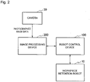
Figure 2] Figure 2 is a block diagram showing a configuration example of the processing system including a workpiece photographed image processing device of one or more embodiments. - [
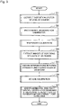
Figure 3] Figure 3 is a flowchart showing an overall operation of the workpiece photographed image processing device of one or more embodiments, and overall processing by a workpiece photographed image processing method of one or more embodiments. - [
Figure 4] Figure 4 is a flowchart showing specific processing of step S1 ofFigure 3 . - [
Figure 5] Figure 5 is a plan view showing an example of a chess board used in step S1 ofFigure 3 . - [
Figure 6] Figure 6 is a diagram showing a chess board photographed image obtained by photographing, with a camera, the chess board shown inFigure 5 . - [
Figure 7] Figure 7 is a flowchart showing specific processing of step S2 ofFigure 3 . - [
Figure 8] Figure 8 is a plan view showing a jig board for calibration used in step S2 ofFigure 3 . - [
Figure 9] Figure 9 is a conceptual diagram showing a state in which the jig board is displaced a plurality of times in the horizontal direction and the vertical direction. - [
Figure 10] Figure 10 is a flowchart showing specific processing of step S3 ofFigure 3 . - [
Figure 11] Figure 11 is a flowchart showing specific processing of step S4 ofFigure 3 . - [
Figure 12] Figure 12 is a diagram showing a state in which an only image in the vicinity of an opening of a jig board photographed image is extracted. - [
Figure 13] Figure 13 is a flowchart showing specific processing of step S5 ofFigure 3 . - [
Figure 14] Figure 14 is a diagram showing intersections formed by straight lines along opening edge images in the jig board photographed image. - [
Figure 15] Figure 15 is a diagram showing a group of intersections formed by the jig board photographed image when the jig board is displaced a plurality of times in the horizontal direction and the vertical direction. - [
Figure 16] Figure 16 is a flowchart showing specific processing of step S6 ofFigure 3 . - [
Figure 17] Figure 17 is a flowchart showing specific processing of step S7 ofFigure 3 . - [
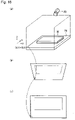
Figure 18] Figure 18 is a conceptual diagram showing the processing executed in step S7 ofFigure 3 . - [
Figure 19] Figure 19 is a block diagram showing a workpiece photographed image processing device according to one or more embodiments. - Hereinafter, a workpiece photographed image processing device, a workpiece photographed image processing method, and a processing system of one or more embodiments will be described with reference to the attached drawings. First, with reference to
Figures 1 and2 , a configuration example of the processing system will be described, in which workpieces are retained by a workpiece retention robot and transported to a processing machine so that the workpieces are processed. - In
Figure 1 , workpieces W are placed on apallet 20, which is an example of a placement location. Here, a plurality of workpieces W are loaded on thepallet 20.Frames pallet 20. Theframe 21a includes one vertical frame and a horizontal frame connected to the upper end portion of the vertical frame. Theframe 21b includes a pair of vertical frames and a horizontal frame connected to the upper end portions of the pair of vertical frames. -
Lighting fixtures frames lighting fixtures lighting fixtures pallet 20 with illumination beams. - An L-
shaped support column 23 including a vertical frame extending to a predetermined height and a horizontal frame connected to the upper end portion of the vertical frame is attached to theframe 21a. Acamera 30 is attached to the distal end of the support column 23 (the horizontal frame). Thecamera 30 is a so-called monocular camera. Thecamera 30 is located at a position deviated from directly above the center of thepallet 20 in a direction away from aworkpiece retention robot 10 so as to photograph thepallet 20 and the workpiece W. In other words, thecamera 30 photographs thepallet 20 and the workpiece W from an obliquely upper position. As a result, thecamera 30 does not interfere with the operation of theworkpiece retention robot 10 to retain and transport the workpiece W placed on thepallet 20. - It is preferable that the workpiece W is irradiated with the illumination beams by the
lighting fixtures camera 30 photographs the workpiece W placed on thepallet 20. When the workpiece W is irradiated with the illumination beams, the edge of the workpiece W is clarified. This makes it easier to detect the position of the workpiece W when the position of the workpiece W is detected by pattern matching. - The articulated
workpiece retention robot 10 is arranged between thepallet 20 and apress brake 40, which is an example of the processing machine. Theworkpiece retention robot 10 includes agripper 11 at the distal end thereof for sucking the workpiece W. Thegripper 11 includes a plurality ofsuction pads 12. Thegripper 11 sucks and retains one uppermost workpiece W, which is transported to thepress brake 40 so that the workpiece is processed. - As shown in
Figure 2 , photographed image data generated by thecamera 30 is supplied to animage processing device 300. Theimage processing device 300 functions as a workpiece photographed image processing device of one or more embodiments. As described above, thecamera 30 is located at the position deviated from directly above the center of thepallet 20 and photographs the workpiece W from the oblique direction. Therefore, the photographed image of the workpiece W is distorted in shape. Theimage processing device 300 corrects the photographed image into an appropriate shape, as will be described later. Theimage processing device 300 detects the position of the workpiece W based on the corrected photographed image, and supplies the detected position information to therobot control device 100. - The
robot control device 100 controls theworkpiece retention robot 10 so as to retain the workpiece W on thepallet 20 based on the position information of the workpiece W. - The
image processing device 300 and therobot control device 100 can be configured with a computer device. By allowing therobot control device 100 to have the function of theimage processing device 300, therobot control device 100 and theimage processing device 300 may be integrated. - The
image processing device 300 executes processing shown in the flowchart ofFigure 3 to correct the photographed image. In step S1, theimage processing device 300 corrects a distortion vector of a lens of thecamera 30. In step S2, theimage processing device 300 photographs a jig board for calibration, and executes temporary calibration in step S3. In step S4, theimage processing device 300 extracts images of the positions of holes of the jig board, and obtains intersections between straight lines along the holes of the jig board in step S5. In step S6, theimage processing device 300 executes the actual calibration. As will be described later, by the processing of steps S1 to S6, conversion parameters are generated for generating a two-dimensional image in which a trapezoidal distortion photographed by thecamera 30 is corrected. - When the
camera 30 photographs thepallet 20 in order to detect the position of the workpiece W placed on thepallet 20, in step S7, theimage processing device 300 generates the two-dimensional image in which the trapezoidal distortion is corrected and supplies the detected position information of the workpiece W to therobot control device 100. - Hereinafter, the processing of steps S1 to S7 will be specifically described.
Figure 4 shows specific processing of step S1. In step S11 ofFigure 4 , thecamera 30 photographs achess board 50 as shown inFigure 5 . In thechess board 50, white squares and black squares are arranged alternately in two orthogonal directions. Thechess board 50 is an example of a lattice pattern, but any graphic pattern may be used. When thecamera 30 photographs thechess board 50, a chess board photographedimage 50i (a first photographed image) as shown inFigure 6 is obtained. The chess board photographedimage 50i is input to theimage processing device 300. Theimage processing device 300 detects grid points of the chess board photographedimage 50i in step S12. - It is preferable that the
camera 30 photographs the chess board 50 a plurality of times in step S11 and supplies a plurality of the chess board photographedimages 50i to theimage processing device 300. At this time, thecamera 30 may photograph thechess board 50 at a plurality of angles. Thechess board 50 may be photographed such that the chess board photographedimage 50i is not distorted into a trapezoidal shape. Alternately, thechess board 50 may be photographed such that the chess board photographedimage 50i is distorted into a trapezoidal shape. When thecamera 30 photographs the chess board 50 a plurality of times, theimage processing device 300 detects grid points of the respective chess board photographedimages 50i, averages the grid points of the respective chess board photographedimages 50i, and detects the grid points of the chess board photographedimage 50i. - As is apparent from a comparison between
Figures 5 and6 , the chess board photographedimage 50i is distorted as compared with thechess board 50 due to distortion aberration and the like of the lens of thecamera 30. In step S13, theimage processing device 300 calculates a first conversion parameter for correcting the distortion due to the lens. Since the expression for calculating the first conversion parameter is known, the details of the expression for calculating the first conversion parameter will be omitted. -
Figure 7 shows specific processing of step S2. In step S21 ofFigure 7 , therobot control device 100 sucks ajig board 60 as shown inFigure 8 with theworkpiece retention robot 10. In step S22, therobot control device 100 displaces thejig board 60 above the pallet 20 a plurality of times in the horizontal direction and the vertical direction, and thecamera 30 photographs thejig board 60 at each position. - The
jig board 60 is made of a sheet metal. As shown inFigure 8 , on thejig board 60, a plurality of groove-shapedopenings 61 parallel to the longitudinal direction and a plurality of groove-shapedopenings 62 parallel to the lateral direction, which is the width direction, are formed. The twoopenings 62 are arranged at both end portions of each of theopenings 61 at a predetermined distance from theopening 61. The direction of theopening 61 and the direction of theopening 62 are orthogonal to each other. AnAR marker 63 is provided on the side of theopening 61 between the twoopenings 62. As an example, theAR marker 63 is provided by attaching a sticker of the AR marker to the sheet metal and fixing the sheet metal to thejig board 60 by way of screwing or the like. The AR marker is an example of a marker. - As shown in
Figure 9 , the width of thejig board 60 is 500 mm. As an example, therobot control device 100 displaces thejig board 60 by 300 mm in the horizontal direction after thecamera 30 photographs thejig board 60. Therobot control device 100 controls theworkpiece retention robot 10 so as to displace thejig board 60 in the horizontal direction eight times from the position at which thejig board 60 is first placed, for example. Therobot control device 100 displaces thejig board 60 in a direction connecting thelighting fixtures Figure 1 . - The
robot control device 100 displaces thejig board 60 in the vertical direction nine times, for example, at each horizontal position. Thecamera 30 photographs thejig board 60 at each horizontal and vertical position. In other words, in one or more embodiments, thecamera 30 photographs thejig board 60 at different positions in the horizontal or vertical position 90 times, and the photographed image data of thejig board 60 at each position is input to theimage processing device 300. - The number of times the
jig board 60 is displaced in the horizontal direction is arbitrary, and in some cases, thejig board 60 may not be displaced in the horizontal direction. The accuracy of the second and third conversion parameters, which will be described later, can be improved if thejig board 60 is displaced in the horizontal direction or if the number of times thejig board 60 is displaced is increased. - The
jig board 60 is displaced in the vertical direction so as to detect the correspondence relation between the position of thejig board 60 in the vertical direction and the size of the photographed image. If the correspondence relation between the position in the height direction and the size is known, it is possible to detect at what height the uppermost workpiece W is when a plurality of the workpieces W are loaded on thepallet 20. If it is known at what height the uppermost workpiece W is, it is possible to reduce the suction error when theworkpiece retention robot 10 sucks the uppermost workpiece W with thegripper 11. When it is not necessary to detect the position of the workpiece W in the height direction, thejig board 60 may not be displaced in the vertical direction. - Now, the
chess board 50 shown inFigure 5 that is used in the processing of step S1 may be provided on the back surface of thejig board 60. When thechess board 50 is provided on the back surface of thejig board 60, thejig board 60 may be sucked by theworkpiece retention robot 10 before step S11 ofFigure 4 to turn over thejig board 60 so that thejig board 60 is photographed by thecamera 30. After that, thejig board 60 may be turned face up to execute the processing of step S22 ofFigure 7 . -
Figure 10 shows specific processing of step S3. In step S31 ofFigure 10 , theimage processing device 300 corrects, by using the first conversion parameter, the image distortion due to the lens that is included in the photographed image of thejig board 60. As a result, the distortion caused by the lens in the photographed image of thejig board 60 is removed. In step S32, theimage processing device 300 detects the positions of theAR markers 63 in the photographed image. - The position at which the
robot control device 100 has displaced thejig board 60 by controlling theworkpiece retention robot 10 is known. In step S33, theimage processing device 300 calculates a second conversion parameter based on the center points of theAR markers 63 on theactual jig board 60 and the center points of theAR markers 63 in the photographed image. The second conversion parameter is a conversion parameter for converting the two-dimensional coordinates in the three-dimensional space photographed by thecamera 30 into the positions of the pixels in the photographed image. - The center point of the
AR marker 63 is an example of a first reference point of thejig board 60. The first reference point may be set other than theAR marker 63. -
Figure 11 shows specific processing of step S4. InFigure 11 , theimage processing device 300 repeats the processing of steps S41 and S42 from the minimum height to the maximum height. In step S41, theimage processing device 300 extracts a photographed image of thejig board 60 at each height. In step S42, theimage processing device 300 extracts only images in the vicinity of theopenings -
Figure 12 shows a jig board photographedimage 60i (a second photographed image) obtained by photographing thejig board 60. The jig board photographedimage 60i includesopening edge images openings marker images 63i of theAR markers 63. Theimage processing device 300 extracts images such that the openingedge images openings actual jig board 60 are known. The positions of theopening edge images openings image processing device 300 can extract images such that the openingedge images -
Figure 13 shows specific processing of step S5. InFigure 13 , theimage processing device 300 repeats the processing of steps S51 and S52 from the minimum height to the maximum height. In step S51, theimage processing device 300 sets straight lines along the openingedge images image 60i at each height. As shown inFigure 14 , as an example, theimage processing device 300 setsstraight lines 71 along the sides of theopening edge images 61i facing themarker images 63i andstraight lines 72 along the sides of theopening edge images 62i facing themarker images 63i. Thestraight lines - Although only one jig board photographed
image 60i is shown inFigure 14 , thestraight lines images 60i at all positions displaced in the horizontal direction as shown inFigure 9 . The twostraight lines 71 are set in the jig board photographedimage 60i at each position in which thejig board 60 is displaced in the horizontal direction. The 14straight lines 72 are connected in a straight line in the jig board photographedimage 60i at each position in the horizontal direction. - Returning to
Figure 13 , in step S52, theimage processing device 300 extracts the intersections between thestraight lines straight lines Figure 14 are indicated by black dots.Figure 15 shows the intersections at all horizontal positions from the minimum height to the maximum height. A group of intersections shown inFigure 15 is obtained by the processing shown inFigure 13 . The higher the vertical position of thejig board 60 is, the larger the jig board photographedimage 60i is. Therefore, in reality, the group of intersections at one horizontal position shown inFigure 15 is in a state in which an interval is slightly wider as the vertical position is higher. - The intersections between the
straight lines jig board 60. More straight lines may be set in the jig board photographedimage 60i to increase the number of the intersections as the second reference points. The second reference point may be set other than the intersection between the straight lines. -
Figure 16 shows specific processing of step S6. In step S61 ofFigure 16 , theimage processing device 300 adds a distortion vector to each intersection in the jig board photographedimage 60i by the first conversion parameter. As a result, the group of intersections shown inFigure 15 is converted into a state in which the distortion vector of the lens of thecamera 30 is added. In step S62, theimage processing device 300 calculates a third conversion parameter based on the positions of the actual intersections of thejig board 60 and the positions of the intersections of the jig board photographedimage 60i to which the distortion vector is added. The third conversion parameter is a conversion parameter for converting the two-dimensional coordinates in the three-dimensional space photographed by thecamera 30 into the positions of the pixels in the photographed image. The third conversion parameter is more accurate than the second conversion parameter. -
Figure 17 shows specific processing of step S7. In order to detect the position of the workpiece W placed on thepallet 20, thecamera 30 photographs thepallet 20 on which the workpiece W is placed. Photographed image data (a third photographed image) generated by thecamera 30 is supplied to theimage processing device 300. - In step S71 of
Figure 17 , theimage processing device 300 specifies, by using the third conversion parameter, the positions of the pixels in the photographed image corresponding to the two-dimensional coordinates and align the pixels at the specified positions in the image memory in a two-dimensional manner. As a result, a corrected photographed image (a fourth photographed image) in which the trapezoidal distortion is corrected is generated. In step S72, theimage processing device 300 detects the position of the workpiece W based on the corrected photographed image, and supplies the position information of the workpiece W to therobot control device 100. -
Figure 18 conceptually shows the processing executed in step S7. InFigure 18, (a) shows a three-dimensional space obtained by photographing, with thecamera 30, thepallet 20 on which the plurality of workpieces W are loaded. Coordinates X, Y, Z are defined as shown in the figure. InFigure 18, (b) is a photographed image including the trapezoidal distortion due to thecamera 30. The position at which the two-dimensional coordinates X and Y in the three-dimensional space is (0,0) is assumed to be the corner of thepallet 20. The position of the pixels in the photographed image of (b) corresponding to the coordinates X, Y = (0,0) of (a) is specified by the third conversion parameter. The pixels at the specified positions in the photographed image of (b) are aligned in a two-dimensional manner as shown in (c). - The
image processing device 300 sequentially increases the coordinate X at the coordinate Y = 0, specifies the position of the pixels in the photographed image corresponding to each coordinate up to the maximum value of X, and aligns the pixels at the specified positions in a two-dimensional manner. Theimage processing device 300 repeats the same operation at the coordinate Y = 1 and thereafter. At this time, theimage processing device 300 may interpolate pixels to align the pixels in a two-dimensional manner. By doing so, the distorted photographed image shown in (b) ofFigure 18 is converted into a two-dimensional image in which the trapezoidal distortion is removed as shown in (c). - By configuring the
image processing device 300 as shown inFigure 19 , the processing shown inFigure 3 can be executed. Theimage processing device 300 is provided with a central processing unit (CPU) 310 and animage memory 320. TheCPU 310 is provided with a first conversionparameter calculation unit 311, a lensdistortion correction unit 312, a second conversionparameter calculation unit 313, a third conversionparameter calculation unit 314, and a trapezoidaldistortion correction unit 315 as functional components. - When the
camera 30 photographs a lattice pattern like thechess board 50, the chess board photographedimage 50i (the first photographed image) is stored in theimage memory 320. The first conversionparameter calculation unit 311 calculates, based on the chess board photographedimage 50i, the first conversion parameter for correcting the image distortion due to the lens of thecamera 30. The first conversion parameter is supplied to the lensdistortion correction unit 312 and the third conversionparameter calculation unit 314. - When the
camera 30 photographs thejig board 60, the jig board photographedimage 60i (the second photographed image) is stored in theimage memory 320. The lensdistortion correction unit 312 corrects, by using the first conversion parameter, the image distortion due to the lens included in the jig board photographedimage 60i. - The second conversion
parameter calculation unit 313 extracts a plurality of the first reference points of thejig board 60 within the jig board photographedimage 60i in which the image distortion is corrected. As an example, the first reference point is the center point of theAR marker 63. The second conversionparameter calculation unit 313 calculates the second conversion parameter based on the actual first reference points of thejig board 60 and the extracted first reference points within the jig board photographedimage 60i. The second conversion parameter is a conversion parameter for converting the two-dimensional coordinates within the three-dimensional space photographed by thecamera 30 into the positions of the pixels within the jig board photographedimage 60i. - The third conversion
parameter calculation unit 314 extracts, by using the second conversion parameter, a region corresponding to an actual predetermined location of thejig board 60 within the jig board photographedimage 60i in which the image distortion is corrected. Examples of the predetermined locations include theopenings parameter calculation unit 314 extracts a plurality of the second reference points based on an image of the extracted region within the jig board photographedimage 60i. As an example, the second reference points are the intersections between the straight lines along theopenings - The third conversion
parameter calculation unit 314 adds, by using the first conversion parameter, the image distortion due to the lens to the second reference points. The third conversionparameter calculation unit 314 calculates the third conversion parameter based on the actual second reference points of thejig board 60 and the second reference points within the jig board photographedimage 60i to which the image distortion due to the lens is added. The third conversion parameter is a conversion parameter for converting the two-dimensional coordinates into the positions of the pixels within the jig board photographedimage 60i. The third conversion parameter is stored in theimage memory 320. - When the
pallet 20 on which the workpiece W is placed is photographed by thecamera 30, the third photographed image is stored in theimage memory 320. The trapezoidaldistortion correction unit 315 specifies, by using the third conversion parameter, to which pixels in the third photographed image the two-dimensional coordinates within the three-dimensional space photographed by thecamera 30 correspond. The trapezoidaldistortion correction unit 315 aligns the specified pixels corresponding to the respective coordinates in a two-dimensional manner, generates the fourth photographed image in which the trapezoidal distortion in the third photographed image is corrected, and stores the fourth photographed image in theimage memory 320. - Since the
CPU 310 detects the position of the workpiece W based on the fourth photographed image, the position of the workpiece W placed on thepallet 20 can be correctly recognized. Since the position of the workpiece W placed on thepallet 20 is correctly recognized, theworkpiece retention robot 10 can accurately retain the workpiece W under the control of therobot control device 100. - The present invention is not limited to the one or more embodiments described above, and various modifications can be made without departing from the gist of the present invention. The
image processing device 300 may be configured such that theCPU 310 executes a computer program to correct the trapezoidal distortion as shown inFigure 18 . Theimage processing device 300 may be composed of hardware such as an integrated circuit, or may be composed of software including a computer program. Alternately, theimage processing device 300 may be composed of a mixture of the both. The software and the hardware can be arbitrarily used. - The present application claims priority based on
Japanese Patent Application No. 2019-191675 filed with the Japan Patent Office on October 21, 2019
Claims (7)
- A workpiece photographed image processing device, comprising:a first conversion parameter calculation unit configured to calculate, based on a first photographed image obtained by photographing a lattice pattern with a camera located at a position deviated from directly above a center of a placement location of a workpiece, a first conversion parameter for correcting an image distortion due to a lens of the camera;a lens distortion correction unit configured to correct, by using the first conversion parameter, the image distortion due to the lens included in a second photographed image obtained by photographing a jig board with the camera;a second conversion parameter calculation unit configured to extract a plurality of first reference points of the jig board within the second photographed image in which the image distortion is corrected by the lens distortion correction unit, and to calculate, based on the actual first reference points of the jig board and the extracted first reference points within the second photographed image, a second parameter for converting two-dimensional coordinates within a three-dimensional space photographed by the camera into positions of pixels within the second photographed image;a third conversion parameter calculation unit configured to extract, by using the second parameter, a region corresponding to an actual predetermined region of the jig board within the second photographed image in which the image distortion is corrected by the lens distortion correction unit, to extract a plurality of second reference points based on an image of the extracted region within the second photographed image, to add, by using the first conversion parameter, the image distortion due to the lens to the second reference points, and to calculate, based on the actual second reference points of the jig board and the second reference points within the second photographed image to which the image distortion due to the lens is added, a third conversion parameter for converting the two-dimensional coordinates within the three-dimensional space into the positions of the pixels within the second photographed image; anda trapezoidal distortion correction unit configured to specify, by using the third conversion parameter, to which pixels in the third photographed image the two-dimensional coordinates within the three-dimensional space photographed by the camera correspond when a third photographed image is generated by photographing, with the camera, the placement location at which the workpiece is placed, to align the specified pixels corresponding to the respective coordinates in a two-dimensional manner, and to generate a fourth photographed image in which a trapezoidal distortion in the third photographed image is corrected.
- The workpiece photographed image processing device according to Claim 1, whereina plurality of markers are provided on the jig board, andthe second conversion parameter calculation unit is configured to extract center points of the markers as the first reference points.
- The workpiece photographed image processing device according to Claim 1 or 2, whereina plurality of openings are formed on the jig board,the second photographed image includes opening edge images corresponding to the openings, andthe third conversion parameter calculation unit is configured toextract a region including the opening edge images within the second photographed image in which the image distortion is corrected, andextract intersections between straight lines along the opening edge images as the second reference points.
- A workpiece photographed image processing method, comprising:calculating, based on a first photographed image obtained by photographing a lattice pattern with a camera located at a position deviated from directly above a center of a placement location of a workpiece, a first conversion parameter for correcting an image distortion due to a lens of the camera;correcting, by using the first conversion parameter, the image distortion due to the lens included in a second photographed image obtained by photographing a jig board with the camera;extracting a plurality of first reference points of the jig board within the second photographed image in which the image distortion is corrected;calculating, based on the actual first reference points of the jig board and the extracted first reference points within the second photographed image, a second parameter for converting two-dimensional coordinates within a three-dimensional space photographed by the camera into positions of pixels within the second photographed image;extracting, by using the second parameter, a region corresponding to an actual predetermined region of the jig board within the second photographed image in which the image distortion is corrected;extracting a plurality of second reference points based on an image of the extracted region within the second photographed image;adding, by using the first conversion parameter, the image distortion due to the lens to the second reference points;calculating, based on the actual second reference points of the jig board and the second reference points within the second photographed image to which the image distortion due to the lens is added, a third conversion parameter for converting the two-dimensional coordinates within the three-dimensional space into the positions of the pixels within the second photographed image; andspecifying, by using the third conversion parameter, to which pixels in the third photographed image the two-dimensional coordinates within the three-dimensional space photographed by the camera correspond when a third photographed image is generated by photographing, with the camera, the placement location at which the workpiece is placed, aligning the specified pixels corresponding to the respective coordinates in a two-dimensional manner, and generating a fourth photographed image in which a trapezoidal distortion in the third photographed image is corrected.
- The workpiece photographed image processing method according to Claim 4, whereina plurality of markers are provided on the jig board, andthe method further comprising extracting center points of the markers as the first reference points.
- The workpiece photographed image processing method according to Claim 4 or 5, whereina plurality of openings are formed on the jig board,the second photographed image includes opening edge images corresponding to the openings, andthe method further comprising:extracting a region including the opening edge images within the second photographed image in which the image distortion is corrected; andextracting intersections between straight lines along the opening edge images as the second reference points.
- A processing system comprising:a camera located at a position deviated from directly above a center of a placement location of a workpiece;an image processing device configured to specify, by using a preliminarily determined conversion parameter, to which pixels in a photographed image two-dimensional coordinates within a photographed three-dimensional space correspond when the photographed image is generated by photographing, with the camera, the placement location at which the workpiece is placed, to align the specified pixels corresponding to the respective coordinates in a two-dimensional manner, and to generate a corrected photographed image in which a trapezoidal distortion in the photographed image is corrected; anda robot control device configured to detect a position of the workpiece at the placement location based on the corrected photographed image, and to control a workpiece retention robot so as to retain the workpiece and transport the workpiece to a processing machine.
Applications Claiming Priority (2)
| Application Number | Priority Date | Filing Date | Title |
|---|---|---|---|
| JP2019191675A JP7269864B2 (en) | 2019-10-21 | 2019-10-21 | Work photographed image processing device and work photographed image processing method |
| PCT/JP2020/038767 WO2021079802A1 (en) | 2019-10-21 | 2020-10-14 | Workpiece photograph image processing device, workpiece photograph image processing method, and machining system |
Publications (3)
| Publication Number | Publication Date |
|---|---|
| EP4049805A1 true EP4049805A1 (en) | 2022-08-31 |
| EP4049805A4 EP4049805A4 (en) | 2023-03-15 |
| EP4049805B1 EP4049805B1 (en) | 2023-12-20 |
Family
ID=75620570
Family Applications (1)
| Application Number | Title | Priority Date | Filing Date |
|---|---|---|---|
| EP20879458.6A Active EP4049805B1 (en) | 2019-10-21 | 2020-10-14 | Workpiece photograph image processing device, workpiece photograph image processing method |
Country Status (4)
| Country | Link |
|---|---|
| US (1) | US12094094B2 (en) |
| EP (1) | EP4049805B1 (en) |
| JP (1) | JP7269864B2 (en) |
| WO (1) | WO2021079802A1 (en) |
Families Citing this family (11)
| Publication number | Priority date | Publication date | Assignee | Title |
|---|---|---|---|---|
| JP7561519B2 (en) * | 2020-05-22 | 2024-10-04 | 株式会社アマダ | Bending system and method of using same |
| US20230273599A1 (en) * | 2021-01-18 | 2023-08-31 | Shinkawa Ltd. | Position control apparatus, position control method, position control recording medium, and bonding apparatus |
| JP7564742B2 (en) * | 2021-03-22 | 2024-10-09 | 株式会社東芝 | Information processing device and information processing method |
| JP7218018B1 (en) | 2021-12-24 | 2023-02-06 | ユーピーアール株式会社 | PALLET DETECTION DEVICE AND PALLET DETECTION METHOD |
| JP7185958B1 (en) | 2021-12-24 | 2022-12-08 | ユーピーアール株式会社 | PALLET DETECTION DEVICE AND PALLET DETECTION METHOD |
| CN114893669B (en) * | 2022-05-26 | 2024-03-26 | 江苏省建筑工程集团有限公司 | Monitoring device and monitoring method applied to installation of tower crane attachment device |
| EP4357041A1 (en) | 2022-10-21 | 2024-04-24 | Bystronic Laser AG | Device and method for automated bending of workpieces |
| CN116071361B (en) * | 2023-03-20 | 2023-07-04 | 深圳思谋信息科技有限公司 | Visual positioning method and device for workpiece, computer equipment and storage medium |
| EP4450920A1 (en) * | 2023-04-21 | 2024-10-23 | SK On Co., Ltd. | Calibration device and equipment diagnosis method using the same |
| JP7642016B2 (en) | 2023-05-16 | 2025-03-07 | Jcom株式会社 | Game record recording system, game record recording device, and game record recording program |
| WO2025069680A1 (en) * | 2023-09-29 | 2025-04-03 | 村田機械株式会社 | Object position detection method and industrial machine |
Family Cites Families (11)
| Publication number | Priority date | Publication date | Assignee | Title |
|---|---|---|---|---|
| CN100465995C (en) * | 2001-06-12 | 2009-03-04 | 奥普提克斯晶硅有限公司 | A method and system for projecting an image onto a screen surface |
| KR100812997B1 (en) * | 2007-03-07 | 2008-03-13 | 삼성전기주식회사 | Keystone correction method and display device |
| JP5365218B2 (en) * | 2009-01-28 | 2013-12-11 | 富士電機株式会社 | Robot vision system and automatic calibration method |
| US9213446B2 (en) * | 2009-04-16 | 2015-12-15 | Nec Corporation | Handwriting input device |
| US9863861B2 (en) * | 2013-02-28 | 2018-01-09 | Perfect Coffee, Inc. | Method and apparatus for particle size determination |
| JP6260891B2 (en) | 2013-08-08 | 2018-01-17 | パナソニックIpマネジメント株式会社 | Image processing apparatus and image processing method |
| JP2015157342A (en) * | 2014-02-25 | 2015-09-03 | セイコーエプソン株式会社 | Robot, robot system, control device and control method |
| WO2018043524A1 (en) * | 2016-09-02 | 2018-03-08 | 倉敷紡績株式会社 | Robot system, robot system control device, and robot system control method |
| JP2018120388A (en) | 2017-01-25 | 2018-08-02 | 株式会社アマダホールディングス | Work detection apparatus and method |
| WO2019049331A1 (en) | 2017-09-08 | 2019-03-14 | 株式会社ソニー・インタラクティブエンタテインメント | Calibration device, calibration system, and calibration method |
| JP2019191675A (en) | 2018-04-19 | 2019-10-31 | セイコーエプソン株式会社 | Transmissive head mounted display apparatus, support system, display control method, and computer program |
-
2019
- 2019-10-21 JP JP2019191675A patent/JP7269864B2/en active Active
-
2020
- 2020-10-14 EP EP20879458.6A patent/EP4049805B1/en active Active
- 2020-10-14 WO PCT/JP2020/038767 patent/WO2021079802A1/en not_active Ceased
- 2020-10-14 US US17/769,729 patent/US12094094B2/en active Active
Also Published As
| Publication number | Publication date |
|---|---|
| US12094094B2 (en) | 2024-09-17 |
| EP4049805B1 (en) | 2023-12-20 |
| EP4049805A4 (en) | 2023-03-15 |
| JP2021065950A (en) | 2021-04-30 |
| WO2021079802A1 (en) | 2021-04-29 |
| JP7269864B2 (en) | 2023-05-09 |
| US20220414843A1 (en) | 2022-12-29 |
Similar Documents
| Publication | Publication Date | Title |
|---|---|---|
| EP4049805B1 (en) | Workpiece photograph image processing device, workpiece photograph image processing method | |
| TWI708216B (en) | Method and system for calibrating vision system in environment | |
| US20240308081A1 (en) | Robot system and control apparatus | |
| US11972589B2 (en) | Image processing device, work robot, substrate inspection device, and specimen inspection device | |
| EP2921267A2 (en) | Robot system, calibration method in robot system, and position correcting method in robot system | |
| CN109926724B (en) | double-CCD positioning marking method, double-CCD positioning marking system and storage medium | |
| EP3847617A1 (en) | Vision system for a robotic machine | |
| TWI547973B (en) | Drawing method and drawing device | |
| JP5545737B2 (en) | Component mounter and image processing method | |
| US8886350B2 (en) | Displacement calculation method, drawing data correction method, substrate manufacturing method, and drawing apparatus | |
| US11230011B2 (en) | Robot system calibration | |
| JP2008270696A (en) | Component mounting position correction method and component mounting apparatus | |
| US20220335642A1 (en) | Workpiece detection device and workpiece detection method | |
| CN115810049B (en) | Methods, apparatus, equipment, media, and products for pose determination based on markers | |
| WO2018139026A1 (en) | Workpiece detection device and method | |
| JPWO2020044491A1 (en) | robot | |
| CN113302027A (en) | Work coordinate generation device | |
| JP6582405B2 (en) | Assembly apparatus, robot hand position correcting method, and robot hand position correcting program | |
| JP6473172B2 (en) | Board work machine | |
| JPH11175150A (en) | Stop position shift amount detection device for moving object | |
| US7614031B2 (en) | Drawing apparatus with drawing data correction function | |
| KR20210101090A (en) | Position Compensation Apparatus and Method of pick and place machine | |
| JPH03241897A (en) | Positional correction of component | |
| CN116896856A (en) | Installation machine and substrate height measurement method | |
| KR102149280B1 (en) | Apparatus for synchronizing reference coordinates |
Legal Events
| Date | Code | Title | Description |
|---|---|---|---|
| STAA | Information on the status of an ep patent application or granted ep patent |
Free format text: STATUS: THE INTERNATIONAL PUBLICATION HAS BEEN MADE |
|
| PUAI | Public reference made under article 153(3) epc to a published international application that has entered the european phase |
Free format text: ORIGINAL CODE: 0009012 |
|
| STAA | Information on the status of an ep patent application or granted ep patent |
Free format text: STATUS: REQUEST FOR EXAMINATION WAS MADE |
|
| 17P | Request for examination filed |
Effective date: 20220419 |
|
| AK | Designated contracting states |
Kind code of ref document: A1 Designated state(s): AL AT BE BG CH CY CZ DE DK EE ES FI FR GB GR HR HU IE IS IT LI LT LU LV MC MK MT NL NO PL PT RO RS SE SI SK SM TR |
|
| DAV | Request for validation of the european patent (deleted) | ||
| DAX | Request for extension of the european patent (deleted) | ||
| A4 | Supplementary search report drawn up and despatched |
Effective date: 20230210 |
|
| RIC1 | Information provided on ipc code assigned before grant |
Ipc: G06T 7/80 20170101ALI20230206BHEP Ipc: G06T 5/00 20060101ALI20230206BHEP Ipc: B25J 13/08 20060101ALI20230206BHEP Ipc: B25J 9/10 20060101AFI20230206BHEP |
|
| P01 | Opt-out of the competence of the unified patent court (upc) registered |
Effective date: 20230518 |
|
| GRAP | Despatch of communication of intention to grant a patent |
Free format text: ORIGINAL CODE: EPIDOSNIGR1 |
|
| STAA | Information on the status of an ep patent application or granted ep patent |
Free format text: STATUS: GRANT OF PATENT IS INTENDED |
|
| INTG | Intention to grant announced |
Effective date: 20230816 |
|
| GRAS | Grant fee paid |
Free format text: ORIGINAL CODE: EPIDOSNIGR3 |
|
| GRAA | (expected) grant |
Free format text: ORIGINAL CODE: 0009210 |
|
| STAA | Information on the status of an ep patent application or granted ep patent |
Free format text: STATUS: THE PATENT HAS BEEN GRANTED |
|
| AK | Designated contracting states |
Kind code of ref document: B1 Designated state(s): AL AT BE BG CH CY CZ DE DK EE ES FI FR GB GR HR HU IE IS IT LI LT LU LV MC MK MT NL NO PL PT RO RS SE SI SK SM TR |
|
| REG | Reference to a national code |
Ref country code: GB Ref legal event code: FG4D |
|
| REG | Reference to a national code |
Ref country code: CH Ref legal event code: EP |
|
| REG | Reference to a national code |
Ref country code: DE Ref legal event code: R096 Ref document number: 602020023219 Country of ref document: DE |
|
| REG | Reference to a national code |
Ref country code: IE Ref legal event code: FG4D |
|
| PG25 | Lapsed in a contracting state [announced via postgrant information from national office to epo] |
Ref country code: GR Free format text: LAPSE BECAUSE OF FAILURE TO SUBMIT A TRANSLATION OF THE DESCRIPTION OR TO PAY THE FEE WITHIN THE PRESCRIBED TIME-LIMIT Effective date: 20240321 |
|
| REG | Reference to a national code |
Ref country code: LT Ref legal event code: MG9D |
|
| PG25 | Lapsed in a contracting state [announced via postgrant information from national office to epo] |
Ref country code: LT Free format text: LAPSE BECAUSE OF FAILURE TO SUBMIT A TRANSLATION OF THE DESCRIPTION OR TO PAY THE FEE WITHIN THE PRESCRIBED TIME-LIMIT Effective date: 20231220 |
|
| REG | Reference to a national code |
Ref country code: NL Ref legal event code: MP Effective date: 20231220 |
|
| PG25 | Lapsed in a contracting state [announced via postgrant information from national office to epo] |
Ref country code: ES Free format text: LAPSE BECAUSE OF FAILURE TO SUBMIT A TRANSLATION OF THE DESCRIPTION OR TO PAY THE FEE WITHIN THE PRESCRIBED TIME-LIMIT Effective date: 20231220 |
|
| PG25 | Lapsed in a contracting state [announced via postgrant information from national office to epo] |
Ref country code: LT Free format text: LAPSE BECAUSE OF FAILURE TO SUBMIT A TRANSLATION OF THE DESCRIPTION OR TO PAY THE FEE WITHIN THE PRESCRIBED TIME-LIMIT Effective date: 20231220 Ref country code: GR Free format text: LAPSE BECAUSE OF FAILURE TO SUBMIT A TRANSLATION OF THE DESCRIPTION OR TO PAY THE FEE WITHIN THE PRESCRIBED TIME-LIMIT Effective date: 20240321 Ref country code: FI Free format text: LAPSE BECAUSE OF FAILURE TO SUBMIT A TRANSLATION OF THE DESCRIPTION OR TO PAY THE FEE WITHIN THE PRESCRIBED TIME-LIMIT Effective date: 20231220 Ref country code: ES Free format text: LAPSE BECAUSE OF FAILURE TO SUBMIT A TRANSLATION OF THE DESCRIPTION OR TO PAY THE FEE WITHIN THE PRESCRIBED TIME-LIMIT Effective date: 20231220 Ref country code: BG Free format text: LAPSE BECAUSE OF FAILURE TO SUBMIT A TRANSLATION OF THE DESCRIPTION OR TO PAY THE FEE WITHIN THE PRESCRIBED TIME-LIMIT Effective date: 20240320 |
|
| REG | Reference to a national code |
Ref country code: AT Ref legal event code: MK05 Ref document number: 1642094 Country of ref document: AT Kind code of ref document: T Effective date: 20231220 |
|
| PG25 | Lapsed in a contracting state [announced via postgrant information from national office to epo] |
Ref country code: NL Free format text: LAPSE BECAUSE OF FAILURE TO SUBMIT A TRANSLATION OF THE DESCRIPTION OR TO PAY THE FEE WITHIN THE PRESCRIBED TIME-LIMIT Effective date: 20231220 |
|
| PG25 | Lapsed in a contracting state [announced via postgrant information from national office to epo] |
Ref country code: SE Free format text: LAPSE BECAUSE OF FAILURE TO SUBMIT A TRANSLATION OF THE DESCRIPTION OR TO PAY THE FEE WITHIN THE PRESCRIBED TIME-LIMIT Effective date: 20231220 Ref country code: RS Free format text: LAPSE BECAUSE OF FAILURE TO SUBMIT A TRANSLATION OF THE DESCRIPTION OR TO PAY THE FEE WITHIN THE PRESCRIBED TIME-LIMIT Effective date: 20231220 Ref country code: NO Free format text: LAPSE BECAUSE OF FAILURE TO SUBMIT A TRANSLATION OF THE DESCRIPTION OR TO PAY THE FEE WITHIN THE PRESCRIBED TIME-LIMIT Effective date: 20240320 Ref country code: NL Free format text: LAPSE BECAUSE OF FAILURE TO SUBMIT A TRANSLATION OF THE DESCRIPTION OR TO PAY THE FEE WITHIN THE PRESCRIBED TIME-LIMIT Effective date: 20231220 Ref country code: LV Free format text: LAPSE BECAUSE OF FAILURE TO SUBMIT A TRANSLATION OF THE DESCRIPTION OR TO PAY THE FEE WITHIN THE PRESCRIBED TIME-LIMIT Effective date: 20231220 Ref country code: HR Free format text: LAPSE BECAUSE OF FAILURE TO SUBMIT A TRANSLATION OF THE DESCRIPTION OR TO PAY THE FEE WITHIN THE PRESCRIBED TIME-LIMIT Effective date: 20231220 |
|
| PG25 | Lapsed in a contracting state [announced via postgrant information from national office to epo] |
Ref country code: IS Free format text: LAPSE BECAUSE OF FAILURE TO SUBMIT A TRANSLATION OF THE DESCRIPTION OR TO PAY THE FEE WITHIN THE PRESCRIBED TIME-LIMIT Effective date: 20240420 |
|
| PG25 | Lapsed in a contracting state [announced via postgrant information from national office to epo] |
Ref country code: CZ Free format text: LAPSE BECAUSE OF FAILURE TO SUBMIT A TRANSLATION OF THE DESCRIPTION OR TO PAY THE FEE WITHIN THE PRESCRIBED TIME-LIMIT Effective date: 20231220 Ref country code: AT Free format text: LAPSE BECAUSE OF FAILURE TO SUBMIT A TRANSLATION OF THE DESCRIPTION OR TO PAY THE FEE WITHIN THE PRESCRIBED TIME-LIMIT Effective date: 20231220 |
|
| PG25 | Lapsed in a contracting state [announced via postgrant information from national office to epo] |
Ref country code: SK Free format text: LAPSE BECAUSE OF FAILURE TO SUBMIT A TRANSLATION OF THE DESCRIPTION OR TO PAY THE FEE WITHIN THE PRESCRIBED TIME-LIMIT Effective date: 20231220 |
|
| PG25 | Lapsed in a contracting state [announced via postgrant information from national office to epo] |
Ref country code: SM Free format text: LAPSE BECAUSE OF FAILURE TO SUBMIT A TRANSLATION OF THE DESCRIPTION OR TO PAY THE FEE WITHIN THE PRESCRIBED TIME-LIMIT Effective date: 20231220 Ref country code: SK Free format text: LAPSE BECAUSE OF FAILURE TO SUBMIT A TRANSLATION OF THE DESCRIPTION OR TO PAY THE FEE WITHIN THE PRESCRIBED TIME-LIMIT Effective date: 20231220 Ref country code: RO Free format text: LAPSE BECAUSE OF FAILURE TO SUBMIT A TRANSLATION OF THE DESCRIPTION OR TO PAY THE FEE WITHIN THE PRESCRIBED TIME-LIMIT Effective date: 20231220 Ref country code: IS Free format text: LAPSE BECAUSE OF FAILURE TO SUBMIT A TRANSLATION OF THE DESCRIPTION OR TO PAY THE FEE WITHIN THE PRESCRIBED TIME-LIMIT Effective date: 20240420 Ref country code: EE Free format text: LAPSE BECAUSE OF FAILURE TO SUBMIT A TRANSLATION OF THE DESCRIPTION OR TO PAY THE FEE WITHIN THE PRESCRIBED TIME-LIMIT Effective date: 20231220 Ref country code: CZ Free format text: LAPSE BECAUSE OF FAILURE TO SUBMIT A TRANSLATION OF THE DESCRIPTION OR TO PAY THE FEE WITHIN THE PRESCRIBED TIME-LIMIT Effective date: 20231220 Ref country code: AT Free format text: LAPSE BECAUSE OF FAILURE TO SUBMIT A TRANSLATION OF THE DESCRIPTION OR TO PAY THE FEE WITHIN THE PRESCRIBED TIME-LIMIT Effective date: 20231220 |
|
| PG25 | Lapsed in a contracting state [announced via postgrant information from national office to epo] |
Ref country code: PL Free format text: LAPSE BECAUSE OF FAILURE TO SUBMIT A TRANSLATION OF THE DESCRIPTION OR TO PAY THE FEE WITHIN THE PRESCRIBED TIME-LIMIT Effective date: 20231220 Ref country code: PT Free format text: LAPSE BECAUSE OF FAILURE TO SUBMIT A TRANSLATION OF THE DESCRIPTION OR TO PAY THE FEE WITHIN THE PRESCRIBED TIME-LIMIT Effective date: 20240422 |
|
| PG25 | Lapsed in a contracting state [announced via postgrant information from national office to epo] |
Ref country code: PT Free format text: LAPSE BECAUSE OF FAILURE TO SUBMIT A TRANSLATION OF THE DESCRIPTION OR TO PAY THE FEE WITHIN THE PRESCRIBED TIME-LIMIT Effective date: 20240422 Ref country code: PL Free format text: LAPSE BECAUSE OF FAILURE TO SUBMIT A TRANSLATION OF THE DESCRIPTION OR TO PAY THE FEE WITHIN THE PRESCRIBED TIME-LIMIT Effective date: 20231220 |
|
| REG | Reference to a national code |
Ref country code: DE Ref legal event code: R097 Ref document number: 602020023219 Country of ref document: DE |
|
| PG25 | Lapsed in a contracting state [announced via postgrant information from national office to epo] |
Ref country code: DK Free format text: LAPSE BECAUSE OF FAILURE TO SUBMIT A TRANSLATION OF THE DESCRIPTION OR TO PAY THE FEE WITHIN THE PRESCRIBED TIME-LIMIT Effective date: 20231220 |
|
| PLBE | No opposition filed within time limit |
Free format text: ORIGINAL CODE: 0009261 |
|
| STAA | Information on the status of an ep patent application or granted ep patent |
Free format text: STATUS: NO OPPOSITION FILED WITHIN TIME LIMIT |
|
| PG25 | Lapsed in a contracting state [announced via postgrant information from national office to epo] |
Ref country code: SI Free format text: LAPSE BECAUSE OF FAILURE TO SUBMIT A TRANSLATION OF THE DESCRIPTION OR TO PAY THE FEE WITHIN THE PRESCRIBED TIME-LIMIT Effective date: 20231220 |
|
| PG25 | Lapsed in a contracting state [announced via postgrant information from national office to epo] |
Ref country code: SI Free format text: LAPSE BECAUSE OF FAILURE TO SUBMIT A TRANSLATION OF THE DESCRIPTION OR TO PAY THE FEE WITHIN THE PRESCRIBED TIME-LIMIT Effective date: 20231220 Ref country code: DK Free format text: LAPSE BECAUSE OF FAILURE TO SUBMIT A TRANSLATION OF THE DESCRIPTION OR TO PAY THE FEE WITHIN THE PRESCRIBED TIME-LIMIT Effective date: 20231220 |
|
| 26N | No opposition filed |
Effective date: 20240923 |
|
| REG | Reference to a national code |
Ref country code: CH Ref legal event code: PL |
|
| PG25 | Lapsed in a contracting state [announced via postgrant information from national office to epo] |
Ref country code: MC Free format text: LAPSE BECAUSE OF FAILURE TO SUBMIT A TRANSLATION OF THE DESCRIPTION OR TO PAY THE FEE WITHIN THE PRESCRIBED TIME-LIMIT Effective date: 20231220 |
|
| PG25 | Lapsed in a contracting state [announced via postgrant information from national office to epo] |
Ref country code: LU Free format text: LAPSE BECAUSE OF NON-PAYMENT OF DUE FEES Effective date: 20241014 Ref country code: BE Free format text: LAPSE BECAUSE OF NON-PAYMENT OF DUE FEES Effective date: 20241031 |
|
| PG25 | Lapsed in a contracting state [announced via postgrant information from national office to epo] |
Ref country code: CH Free format text: LAPSE BECAUSE OF NON-PAYMENT OF DUE FEES Effective date: 20241031 |
|
| REG | Reference to a national code |
Ref country code: BE Ref legal event code: MM Effective date: 20241031 |
|
| PG25 | Lapsed in a contracting state [announced via postgrant information from national office to epo] |
Ref country code: IE Free format text: LAPSE BECAUSE OF NON-PAYMENT OF DUE FEES Effective date: 20241014 |
|
| PGFP | Annual fee paid to national office [announced via postgrant information from national office to epo] |
Ref country code: DE Payment date: 20251021 Year of fee payment: 6 |
|
| PGFP | Annual fee paid to national office [announced via postgrant information from national office to epo] |
Ref country code: GB Payment date: 20251022 Year of fee payment: 6 |
|
| PGFP | Annual fee paid to national office [announced via postgrant information from national office to epo] |
Ref country code: IT Payment date: 20251024 Year of fee payment: 6 |
|
| PGFP | Annual fee paid to national office [announced via postgrant information from national office to epo] |
Ref country code: FR Payment date: 20251030 Year of fee payment: 6 |
|
| PG25 | Lapsed in a contracting state [announced via postgrant information from national office to epo] |
Ref country code: CY Free format text: LAPSE BECAUSE OF FAILURE TO SUBMIT A TRANSLATION OF THE DESCRIPTION OR TO PAY THE FEE WITHIN THE PRESCRIBED TIME-LIMIT; INVALID AB INITIO Effective date: 20201014 |
|
| PG25 | Lapsed in a contracting state [announced via postgrant information from national office to epo] |
Ref country code: HU Free format text: LAPSE BECAUSE OF FAILURE TO SUBMIT A TRANSLATION OF THE DESCRIPTION OR TO PAY THE FEE WITHIN THE PRESCRIBED TIME-LIMIT; INVALID AB INITIO Effective date: 20201014 |