EP4049702B1 - Patientenschnittstelle für cpap therapie - Google Patents
Patientenschnittstelle für cpap therapie Download PDFInfo
- Publication number
- EP4049702B1 EP4049702B1 EP22157184.7A EP22157184A EP4049702B1 EP 4049702 B1 EP4049702 B1 EP 4049702B1 EP 22157184 A EP22157184 A EP 22157184A EP 4049702 B1 EP4049702 B1 EP 4049702B1
- Authority
- EP
- European Patent Office
- Prior art keywords
- assembly
- patient
- cylindrical wall
- patient interface
- headgear
- Prior art date
- Legal status (The legal status is an assumption and is not a legal conclusion. Google has not performed a legal analysis and makes no representation as to the accuracy of the status listed.)
- Active
Links
Images













Classifications
-
- A—HUMAN NECESSITIES
- A61—MEDICAL OR VETERINARY SCIENCE; HYGIENE
- A61M—DEVICES FOR INTRODUCING MEDIA INTO, OR ONTO, THE BODY; DEVICES FOR TRANSDUCING BODY MEDIA OR FOR TAKING MEDIA FROM THE BODY; DEVICES FOR PRODUCING OR ENDING SLEEP OR STUPOR
- A61M16/00—Devices for influencing the respiratory system of patients by gas treatment, e.g. ventilators; Tracheal tubes
- A61M16/06—Respiratory or anaesthetic masks
- A61M16/0605—Means for improving the adaptation of the mask to the patient
- A61M16/0611—Means for improving the adaptation of the mask to the patient with a gusset portion
-
- A—HUMAN NECESSITIES
- A61—MEDICAL OR VETERINARY SCIENCE; HYGIENE
- A61M—DEVICES FOR INTRODUCING MEDIA INTO, OR ONTO, THE BODY; DEVICES FOR TRANSDUCING BODY MEDIA OR FOR TAKING MEDIA FROM THE BODY; DEVICES FOR PRODUCING OR ENDING SLEEP OR STUPOR
- A61M16/00—Devices for influencing the respiratory system of patients by gas treatment, e.g. ventilators; Tracheal tubes
- A61M16/08—Bellows; Connecting tubes ; Water traps; Patient circuits
- A61M16/0816—Joints or connectors
-
- A—HUMAN NECESSITIES
- A61—MEDICAL OR VETERINARY SCIENCE; HYGIENE
- A61M—DEVICES FOR INTRODUCING MEDIA INTO, OR ONTO, THE BODY; DEVICES FOR TRANSDUCING BODY MEDIA OR FOR TAKING MEDIA FROM THE BODY; DEVICES FOR PRODUCING OR ENDING SLEEP OR STUPOR
- A61M16/00—Devices for influencing the respiratory system of patients by gas treatment, e.g. ventilators; Tracheal tubes
- A61M16/06—Respiratory or anaesthetic masks
-
- A—HUMAN NECESSITIES
- A61—MEDICAL OR VETERINARY SCIENCE; HYGIENE
- A61M—DEVICES FOR INTRODUCING MEDIA INTO, OR ONTO, THE BODY; DEVICES FOR TRANSDUCING BODY MEDIA OR FOR TAKING MEDIA FROM THE BODY; DEVICES FOR PRODUCING OR ENDING SLEEP OR STUPOR
- A61M16/00—Devices for influencing the respiratory system of patients by gas treatment, e.g. ventilators; Tracheal tubes
- A61M16/06—Respiratory or anaesthetic masks
- A61M16/0605—Means for improving the adaptation of the mask to the patient
-
- A—HUMAN NECESSITIES
- A61—MEDICAL OR VETERINARY SCIENCE; HYGIENE
- A61M—DEVICES FOR INTRODUCING MEDIA INTO, OR ONTO, THE BODY; DEVICES FOR TRANSDUCING BODY MEDIA OR FOR TAKING MEDIA FROM THE BODY; DEVICES FOR PRODUCING OR ENDING SLEEP OR STUPOR
- A61M16/00—Devices for influencing the respiratory system of patients by gas treatment, e.g. ventilators; Tracheal tubes
- A61M16/06—Respiratory or anaesthetic masks
- A61M16/0605—Means for improving the adaptation of the mask to the patient
- A61M16/0616—Means for improving the adaptation of the mask to the patient with face sealing means comprising a flap or membrane projecting inwards, such that sealing increases with increasing inhalation gas pressure
-
- A—HUMAN NECESSITIES
- A61—MEDICAL OR VETERINARY SCIENCE; HYGIENE
- A61M—DEVICES FOR INTRODUCING MEDIA INTO, OR ONTO, THE BODY; DEVICES FOR TRANSDUCING BODY MEDIA OR FOR TAKING MEDIA FROM THE BODY; DEVICES FOR PRODUCING OR ENDING SLEEP OR STUPOR
- A61M16/00—Devices for influencing the respiratory system of patients by gas treatment, e.g. ventilators; Tracheal tubes
- A61M16/06—Respiratory or anaesthetic masks
- A61M16/0605—Means for improving the adaptation of the mask to the patient
- A61M16/0633—Means for improving the adaptation of the mask to the patient with forehead support
-
- A—HUMAN NECESSITIES
- A61—MEDICAL OR VETERINARY SCIENCE; HYGIENE
- A61M—DEVICES FOR INTRODUCING MEDIA INTO, OR ONTO, THE BODY; DEVICES FOR TRANSDUCING BODY MEDIA OR FOR TAKING MEDIA FROM THE BODY; DEVICES FOR PRODUCING OR ENDING SLEEP OR STUPOR
- A61M16/00—Devices for influencing the respiratory system of patients by gas treatment, e.g. ventilators; Tracheal tubes
- A61M16/06—Respiratory or anaesthetic masks
- A61M16/0683—Holding devices therefor
-
- A—HUMAN NECESSITIES
- A61—MEDICAL OR VETERINARY SCIENCE; HYGIENE
- A61M—DEVICES FOR INTRODUCING MEDIA INTO, OR ONTO, THE BODY; DEVICES FOR TRANSDUCING BODY MEDIA OR FOR TAKING MEDIA FROM THE BODY; DEVICES FOR PRODUCING OR ENDING SLEEP OR STUPOR
- A61M16/00—Devices for influencing the respiratory system of patients by gas treatment, e.g. ventilators; Tracheal tubes
- A61M16/20—Valves specially adapted to medical respiratory devices
- A61M16/208—Non-controlled one-way valves, e.g. exhalation, check, pop-off non-rebreathing valves
-
- A—HUMAN NECESSITIES
- A61—MEDICAL OR VETERINARY SCIENCE; HYGIENE
- A61M—DEVICES FOR INTRODUCING MEDIA INTO, OR ONTO, THE BODY; DEVICES FOR TRANSDUCING BODY MEDIA OR FOR TAKING MEDIA FROM THE BODY; DEVICES FOR PRODUCING OR ENDING SLEEP OR STUPOR
- A61M2202/00—Special media to be introduced, removed or treated
- A61M2202/02—Gases
- A61M2202/0225—Carbon oxides, e.g. Carbon dioxide
-
- A—HUMAN NECESSITIES
- A61—MEDICAL OR VETERINARY SCIENCE; HYGIENE
- A61M—DEVICES FOR INTRODUCING MEDIA INTO, OR ONTO, THE BODY; DEVICES FOR TRANSDUCING BODY MEDIA OR FOR TAKING MEDIA FROM THE BODY; DEVICES FOR PRODUCING OR ENDING SLEEP OR STUPOR
- A61M2205/00—General characteristics of the apparatus
- A61M2205/42—Reducing noise
-
- A—HUMAN NECESSITIES
- A61—MEDICAL OR VETERINARY SCIENCE; HYGIENE
- A61M—DEVICES FOR INTRODUCING MEDIA INTO, OR ONTO, THE BODY; DEVICES FOR TRANSDUCING BODY MEDIA OR FOR TAKING MEDIA FROM THE BODY; DEVICES FOR PRODUCING OR ENDING SLEEP OR STUPOR
- A61M2205/00—General characteristics of the apparatus
- A61M2205/58—Means for facilitating use, e.g. by people with impaired vision
- A61M2205/583—Means for facilitating use, e.g. by people with impaired vision by visual feedback
-
- A—HUMAN NECESSITIES
- A61—MEDICAL OR VETERINARY SCIENCE; HYGIENE
- A61M—DEVICES FOR INTRODUCING MEDIA INTO, OR ONTO, THE BODY; DEVICES FOR TRANSDUCING BODY MEDIA OR FOR TAKING MEDIA FROM THE BODY; DEVICES FOR PRODUCING OR ENDING SLEEP OR STUPOR
- A61M2206/00—Characteristics of a physical parameter; associated device therefor
- A61M2206/10—Flow characteristics
Definitions
- the present invention relates to a patient interface, and more particularly, to a patient interface used for a continuous positive airway pressure (CPAP) respirator.
- CPAP continuous positive airway pressure
- a continuous positive airway pressure (CPAP) respirator is equipment used for treating obstructive sleep apnea (OSA).
- OSA obstructive sleep apnea
- an air flow is generated from air for breathing by a flow generator, and the air for breathing is delivered through a delivery tube to the patient interface and then provided to the patient.
- Air exhaled by the patient is also discharged through the patient interface.
- the patient interface accommodates the air flow generated by the flow generator and the air flow exhaled by the patient, and at the same time an air discharge function needs to be provided for the air flow exhaled by the patient.
- air flow disturbances are likely to occur in the patient interface, and may thus easily cause noise and lead to discharge difficulties of carbon dioxide in the gas exhaled by the patient.
- EP 3 622 995 A1 discloses a respiratory mask comprising a nose cushion assembly.
- the nose cushion assembly comprises: a base body having a base intake portion and a base connection portion, and comprising: an air routing piece disposed inside the base body and having a partitioning wall and a wall connection piece; and a buffering piece connecting the base connection portion and enclosing a nose containing room, the nose containing room connecting the inside of the base body; wherein the wall connection piece is disposed outside the partitioning wall and connects the base intake portion; wherein the inside of the partitioning wall encloses an air intake zone, the air intake zone is approximately at the center of the base intake portion, and an air outtake zone is defined between the partitioning wall and the base intake portion.
- WO 2017/049357 A1 discloses an elbow assembly for a patient interface, the elbow assembly comprising: a swivel component adapted to connect to a patient interface; and an elbow component adapted to connect to an air circuit, wherein the swivel component is coupled to the elbow component by a ball and socket joint and a hinge joint which allows the elbow component to pivot relative to the swivel component about a single axis.
- the swivel component includes an inner radial wall and an outer radial wall that define a radial channel leading to a plurality of vent holes for gas washout. At least a portion of the inner radial wall includes an inwardly extending lip or chevron structured and arranged to redirect flow in a manner that reduces noise and/or minimizes flow directly onto sensitive parts of a patient's face.
- WO 2017/049356 A1 discloses a patient interface for sealed delivery of a flow of air at a continuously positive pressure with respect to ambient air pressure to an entrance to a patient's airways including at least entrance of a patient's nares, wherein the patient interface is configured to maintain a therapy pressure in a range of about 4 cmH 2 0 to about 30 cmH 2 0 above ambient air pressure in use, throughout a patient's respiratory cycle, while the patient is sleeping, to ameliorate sleep disordered breathing.
- the patient interface comprises: a frame assembly including connectors operatively attachable to headgear; a cushion assembly provided to the frame assembly, the cushion assembly including a shell and a seal-forming structure provided to the shell and structured to form a seal with a patient's nose and/or mouth, the shell and the seal-forming structure cooperating to form a plenum chamber; and an air delivery connector provided to the frame assembly, the air delivery connector operatively connected to an air delivery tube for supplying the air at positive pressure along an air flow path; wherein the cushion assembly is structured to releasably connect to the frame assembly independently of the air delivery connector; wherein the air delivery connector is structured to releasably connect to the frame assembly independently of the cushion assembly; wherein a first seal for the air flow path is formed between the air delivery connector and the frame assembly, and a separate second seal is formed between the frame assembly and the cushion assembly; and wherein the first seal comprises a dynamic diametric seal and a dynamic face seal, and the second seal comprises a static diametric seal and a
- WO 2004/022147 A1 discloses an elbow assembly for a respiratory mask comprising an elbow, wherein the elbow comprises: a) a first end portion comprising a surface adapted to engage a surface of a gas delivery tube; and b) a second end portion provided to the mask, wherein the elbow further defines: i) an inlet port to deliver incoming gas in a first direction to a nasal breathing cavity defined by the mask, and ii) an exhaust port separated from the inlet port by at least one baffle, wherein the baffle has at least one arcuate portion, as viewed along the second end, and the baffle is configured to direct exhaust gas away from the nasal breathing cavity in a second direction that is substantially opposite to the first direction.
- WO 2016/206364 A1 discloses a face mask assembly comprising: a frame, provided with a first air outlet; a forehead support, provided with a second air outlet; and a flow-guiding member, comprising a first end fitting the first air outlet, a second end fitting the second air outlet, and a passageway running from the first end through to the second end, the channel being in communication with the first air outlet and the second air outlet.
- the exhaust passageway arranged between the forehead support and the frame is advantageous to the emission of carbon dioxide, thus preventing the carbon dioxide from being repeatedly inhaled, and also reducing the noise produced by opposing air flows.
- the present invention provides a patient interface for continuous positive airway pressure (CPAP) therapy as defined in claim 1. Further preferred embodiments of the present invention are defined in the dependent claims.
- CPAP continuous positive airway pressure
- CPAP continuous positive airway pressure
- the present disclosure provides a patient interface that delivers an air flow within a treatment pressure range of 2 to 30 cm H2O generated by an air flow generator to airways of a patient at a continuous positive pressure relative to the ambient air pressure.
- the patient interface includes a cushion assembly, a headgear assembly, a frame assembly and an elbow assembly.
- the cushion assembly includes a shield, a cylindrical wall and a soft sealing member.
- the shield has an opening structured on a first end of the cushion assembly, and a ring structure projecting from the opening in a direction towards the first end of the cushion assembly.
- the cylindrical wall is provided to the opening by a plurality of support structures and formed as concentric with the opening, and projects in two opposite directions along an axis of the opening.
- the soft sealing member is provided to the shield of the cushion assembly and together form a breathing chamber, and is adapted to airtightly press against at least portion of a face of a patient.
- the frame assembly is adapted to engage with the cushion assembly, includes a plurality of slots adapted to attach to respective ones of the straps in use, and is not provided with a forehead support.
- the elbow assembly is adapted to be connected to an air delivery tube connected to a flow generator so as to deliver an air flow to airways of the patient when in use, and is non-detachably provided to the frame assembly. When attached, the frame assembly and the cushion assembly are rotatable in between.
- a cushion assembly includes a hollow structure, a cylindrical wall and a sealing assembly.
- the hollow structure has a central aperture structured on a first end of the cushion assembly to deliver an air flow when in use, and a protruding structure projecting from the central aperture in a direction towards the first end of the cushion assembly.
- the cylindrical wall is provided to the central aperture, and is structured to be substantially concentric with the central aperture.
- the cylindrical wall projects in the manner of having a same diameter towards the first end of the cushion assembly by a first distance, and projects in a manner of having a different diameter towards the second end opposite to the first end of the cushion assembly by a second distance, wherein the first distance is greater than the second distance.
- the sealing assembly is provided to the hollow structure of the cushion assembly and together formed a breathing chamber, and is adapted to seal a face of a patient in response to wearing of the patient to prevent the hollow structure from contacting the face of the patient.
- a frame assembly includes a transition ring structure and a headgear secure assembly.
- the transition ring structure is provided to the cushion assembly by means of a rigid-to-rigid connection, and has one end for arranging the elbow assembly and allowing 360-degree rotation of the elbow assembly.
- the headgear secure assembly is adapted to engage with the transition ring structure, and has a central opening for accommodating the elbow assembly.
- the headgear secure assembly includes a pair of headgear clip attachment portions adapted to engaged with the corresponding pair of headgear clips so as to attach to the corresponding lower straps, and a pair of upper openings adapted to attach to the corresponding upper straps to secure the headgear assembly to the head of the patient when in use.
- the headgear secure assembly is not provided with a forehead support.
- a cushion assembly includes a hollow structure and a cylindrical wall.
- a seal forming assembly further included is structured to form sealing with a nose and/or a mouth of a patient.
- the seal forming assembly and the hollow structure together form an inflating chamber that applies a pressure to a treatment pressure, and a first support area and a second support area of the seal forming assembly together prevent the hollow structure from contacting a face of the patient.
- the thickness of the first support area is substantially greater than the thickness of the second support area, and the thickness of the first support area gradually decreases towards the second support area.
- a border is formed between the first support area and the second support area on the seal forming assembly, and the thickness of the seal forming assembly on the border is substantially constant.
- the headgear assembly includes a plurality of upper straps, a plurality of lower straps, and a rear strap assembly.
- the upper straps are configured to extend to above ears of a patient when in use.
- the lower straps are configured to extend to below ears of a patient when in use.
- the rear strap assembly is provided to the upper straps and the lower straps.
- the rear strap assembly includes a top portion, a plurality of side portions and a bottom portion.
- the top portion is provided between the side portions, the bottom portion is provided between the side portions and the lower straps, and the upper straps are provided to the corresponding side portions.
- a first strap distance between an intersection of each side portion and the top portion may be smaller than a second strap distance between an intersection of each side portion and the bottom portion, and the first strap distance may be greater than a third strap distance between the intersection of each side portion and each upper strap.
- the elbow assembly is provided to the transition ring structure and is 360-degree rotatable, and includes a first end, a second end and a body.
- the first end has a bent outer structure.
- the second end is adapted to connect to an air delivery tube of the flow generator so as to deliver an air flow to airways of a patient when in use.
- the bent outer structure of the first end and at least a portion of the transition ring structure together form in a non-releasable manner an air pathway when in use.
- the transition ring structure (or referred to as a connecting ring structure) and the cushion assembly can be structured to attach with each other in a non-resist movement manner between the two.
- the hollow structure (or referred to as a shield) and the sealing assembly (or referred to as a seal forming assembly or a soft sealing member) may be integral-molded.
- any part of the seal forming assembly may exclude a double-layer structure.
- the cushion assembly, the elbow assembly and the headgear secure assembly may exclude direct physical contact/engagement in between.
- the embodiments achieve multiplied effects, and the patient interface can be stably secured on the face of a patient with comfort and effectively reduce a noise level.
- a patient interface disclosed in the embodiments below relates to delivery of an air flow generated by a flow generator to airways of a patient (or other individual wearing the patient interface) to further construct a treatment system.
- a flow generator can apply a treatment pressure to a part such as airways of a patient or an entrance of airways of a patient, wherein the entrance of the airway of a patient includes at least, for example, an entrance of a nose cavity and/or an entrance of a mouth cavity of a patient.
- the treatment pressure is defined as a continuous positive pressure relative to an atmosphere where a patient is located, and is, for example, a continuous positive pressure between a pressure range of 2 cm H2O to 30 cm H2O.
- the treatment pressure is capable of improving a situation of breathing disorders caused by such as sleep breathing disorders of a patient.
- FIG. 1 shows a three-dimensional schematic diagram of a patient interface according to an embodiment of the present invention
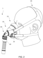
- FIG. 2 shows a three-dimensional schematic diagram of a patient interface worn at a head of a patient according to an embodiment of the present invention
- the patient interface in the treatment system serves as an interface secured at a head of a patient, and is for delivering an air flow generated by a flow generator to airways of the patient or an entrance of airways of the patient.
- the present patient interface is designed such that, even without a forehead support, the patient interface can be stably secured at an appropriate position of the head of the patient with coordination of various parts, and a smooth flow field is formed between the air flow delivered to the patient and an air flow exhaled by the patient, allowing the patient under treatment or the wearer to receive positive-pressure treatment in a stable and comfortable treatment environment.
- the patient interface 1 includes a cushion assembly 10, a headgear assembly 20, headgear clips 30, an elbow assembly 40 and a frame assembly 50.
- the frame assembly 50 with the cushion assembly 10 engaging one end of the frame assembly 50, the patient interface 1 is stably secured on an appropriate position of the face of the patient.
- a breathing chamber may be defined between the cushion assembly 10 and the face of the patient. The breathing chamber receives and inputs the positive-pressure air flow sent from the elbow assembly 40 to airways of the patient, and at the same time, the elbow assembly 40 also receives and outputs an air flow exhaled by the patient to the ambient environment.
- the other end of the frame assembly 50 may be used for arranging the elbow assembly 40, such that the air flow delivered from the flow generator (not shown) through an air delivery tube 60 is guided by the elbow assembly 40 and flows into the breathing chamber through the frame assembly 50.
- the frame assembly 50 enables the headgear assembly 20 to be placed around a predetermined part of a head of the patient through an attachment position of the frame assembly 50 and the headgear assembly 20 are directly and/or indirectly attached therewith, and the attachment is also designed to avoid covering regions where may cause uncomfortable situation to the patient (for example, ears).
- an indirect attachment may be formed by the headgear clips 30 between the frame assembly 50 and a portion of the headgear assembly 20.
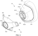
- FIG. 3 shows a three-dimensional schematic diagram of a frame assembly engaged with a cushion assembly
- FIG. 4 shows a three-dimensional schematic diagram of the frame assembly in FIG. 3 from another perspective.
- the frame assembly 50 includes a plurality of slots 501 on two opposite side edges thereof.
- the slots 501 may be used for direct and/or indirectly attachment to the headgear assembly 20.
- the examples in FIG. 1 and FIG. 2 include attachment of two modes (direct and indirect), two slots 501 on an upper portion of the frame assembly 50 are for direct attachment to corresponding straps in the headgear assembly 20, and two slots 501 on a lower portion of the frame assembly 50 are for indirect attachment to corresponding straps in the headgear assembly 20 through an additional pair of headgear clips 30.
- the indirect attachment of the lower portion of the frame assembly 50 can further provide the patient or the wearer with enhanced comfort and convenience during putting on and taking off.
- the headgear clips 30 can be operated to be attached to the slots 501 or removed from the slots 501 with enhanced convenience.
- the replaceable headgear clips 30 also provides degree of freedom of rotation, providing the headgear assembly 20 with options of different attachment angles when attached to the frame assembly 50.
- the cushion assembly 10 includes a shield 101, a cylindrical wall 102 and a sealing assembly 103.
- the shield 101 has an opening structured on a first end of the cushion assembly 10, and a ring structure 1011 projecting from an edge of the opening in a direction towards the first end of the cushion assembly 10.
- the cylindrical wall 102 is provided to the opening by a plurality of support structures 1021 and is concentric with the opening.
- the sealing assembly 103 is a softer assembly, or may be referred to as a soft sealing member.
- the sealing assembly 103 is provided to the shield 101.
- a breathing chamber is formed by a space between the sealing assembly 103 coordinating with the shield 101 and the face of the patient.
- the sealing assembly 103 is adapted to airtightly press against at least portion of the face of the patient.
- the shield 101 and the sealing assembly 103 may be integral-molded.
- the ring structure 1011 of the cushion assembly 10 is provided with a rotation limiting block 1012 at an upper edge
- the frame assembly 50 is provided with a rotation limiting notch 503 at the opening 502.
- the rotation limiting notch 503 is, for example, a notch formed on a limiting wall 5031, so as to achieve a limiting function.
- the rotation limiting block 1012 may be blocked by the rotation limiting notch 503, so the relative rotation between the cushion assembly 10 and the frame assembly 50 can be achieved but limited (not 360 degree free rotation).
- the limiting wall 5031 is structured on one end of the frame assembly 50 facing the cushion assembly 10, and the limiting wall 5031 is a wall structure projecting in a direction towards the cushion assembly 10.
- the shield 101 may be provided with an alignment guide 1013, and the frame assembly 50 is provided correspondingly with an alignment indicator 504, so as to provide a user with guidance for mounting the cushion assembly 10 on the frame assembly 50. Meanwhile, on the basis of the coordination of the alignment guide 1013 and the alignment indicator 504, an extent of relative displacement between the cushion assembly 10 and the frame assembly 50 after the mounting may also be an indication for the user or the patient.
- FIG. 5 shows a three-dimensional schematic diagram of a frame assembly.
- the frame assembly 50 includes a transition ring structure 510 and a headgear secure assembly 520.
- the transition ring structure 510 has one end used for engaging with the cushion assembly 10, and the other end used for engaging with the headgear secure assembly 520.
- the headgear secure assembly 520 and the cushion assembly 10 may be engaged with outer surfaces of two end edges of the transition ring structure 510, so that the headgear secure assembly 520 and the cushion assembly 10 may exclude direct physical contact/engagement in between.
- the transition ring structure 510 serves as a connection medium between the headgear secure assembly 520 and the cushion assembly 10, and may also be regarded as a connecting ring structure.
- the headgear secure assembly 520 includes a pair of upper openings 521, a pair of headgear attachment portions 522 and a central opening 523.
- the central opening 523 is for accommodating the elbow assembly 40
- the pair of headgear clip attachment portions 522 are for attaching the corresponding headgear clips 30, and the pair of upper openings 521 are for attaching the corresponding straps of the headgear assembly 20.
- the elbow assembly 40 is secured in the central opening 523 by means of being engaged with an inner surface of the transition ring structure 510.
- the elbow assembly 40 may be provided to the transition ring structure 510 further by a non-detachable manner.
- the headgear secure assembly 520 and the cushion assembly 10 are engaged on the outer surfaces at two end edges of the transition ring structure 510, and the elbow assembly 40 is engaged on the inner surface of the transition ring structure 510.
- the cushion assembly 10, the elbow assembly 40 and the headgear secure assembly 520 are not in direct physical contact/engagement in a state of use after the engagement.
- FIG. 6 shows a three-dimensional schematic diagram of a cushion assembly arranged on a seal forming assembly. Via an engaging portion 143 of the seal forming assembly 140, a cushion assembly 10' and the seal forming assembly 140 are engaged. The engagement may be implemented by means of injection molding or overmolding.
- the seal forming assembly 140 is adapted to seal the face of a patient in use, and accordingly, the cushion assembly 10' and the seal forming assembly 140 together form an inflating chamber that can be applied a pressure to a treatment pressure due to the sealing of the patient's face.
- the seal forming assembly 140 includes a first support area 141 and a second support area 142.
- the first support area 141 is provided on an end portion 104 of a second end of the cushion assembly 10'.
- the end portion 104 is an engaging portion for engaging (for example, by injection molding or overmolding) to the first support area 141.
- the second support area 142 is provided at the first support area 141, and allows a support area to extend to different extents.
- Between the first support area 141 and the second support area 142 is a border 144, and the border 144 is formed based on a degree of change in the thickness of the two support areas.
- a vicinity between the first support area 141 and the end portion 104 may also be referred to as a first border
- a vicinity between the first support area 141 and the second support area 142 may be referred to as a second border.
- the seal forming assembly 140 does not include any part that is a double-layer structure, and the second support area 142 at least contacts a nose bridge and/or a chin area of the patient.
- the first support area 141 and the second support area 142 may be together used for preventing a specific portion of the cushion assembly 10 from contacting the face of the patient.
- the specific portion refers to a portion of the end portion 104 of the cushion assembly 10' that extends in a direction towards a first end opposite to the second end.
- the thickness of the first support area 141 is substantially greater than the thickness of the second support area 142, and the thickness of the first support area 141 gradually decreases in a direction towards the second support area 142.
- the thickness of the border 144 formed between different support areas on the seal forming assembly 140 may be substantially constant.
- FIG. 7 shows a front view of a seal forming assembly
- FIG. 8 shows a section schematic diagram along section line AA in FIG. 7
- FIG. 9 shows a section schematic diagram along section line BB in FIG. 7
- FIG. 10 shows a section schematic diagram along section line CC in FIG. 7
- FIG. 7 to FIG. 10 illustrate situations where the thickness of the seal forming assembly 140 exhibits different degrees of change in the thickness in various directions (change in distance).
- An element symbol 144 (particularly as indicated at a cross-section) indicated in FIG. 8 to FIG. 10 may correspond to the border 144 between the first support area 141 and the second support area 142. The position of the border 144 in FIG.
- FIG. 8 is the closest to the engaging portion 143
- the position of the border 144 in FIG. 10 is the second closest to the engaging portion 143
- the position of the border 144 in FIG. 9 is the farthest away from the engaging portion 143.
- the element symbol 144 indicated in FIG. 8 and FIG. 10 shows that the thickness of the seal forming assembly 140 gradually decreases from the engaging portion 143, and becomes substantially constant at the border 144.
- the thickness in the first support area 141 varies, and the second support area 142 is substantially kept at a same thickness.
- the thickness of an end portion of the second support area 142 in a direction away from the first support area 141 may be configured to increase so as to form an end edge 1421 serving as a rim.
- a vertical distance is present between a position of each point on the engaging portion 143 of the seal forming assembly 140 and the border 144. Among the vertical distances formed, corresponding vertical distances adjacent to cheeks and cheekbones of the patient when in use are greater than corresponding vertical distances adjacent to the nose and the chin of the patient when in use.
- the vertical distance is, for example, a vertical distance formed by a distance between a tangent point of a tangent plane on the engaging portion 143 and a tangent point of a corresponding tangent plane on the border 144, along the surface of the seal forming assembly 140.
- a connecting line between the two tangent points are both perpendicular to the tangent plane on the engaging portion 143 and the corresponding tangent plane on the border 144.
- a position extended from the first support area 141 and of which the thickness gradually decreases to a predetermined thickness is defined as the border 144, and the predetermined thickness may be any value selected from a range of 0.50 mm to 0.70 mm, further providing a wearer with enhanced wearing comfort.
- Any value within the range 0.50 to 0.70 mm is, for example, any value selected from 0.5, 0.51, 0.52, 0.53, 0.54, 0.55, 0.56, 0.57, 0.58, 0.59, 0.6, 0.61, 0.62, 0.63, 0.64, 0.65, 0.66, 0.67, 0.68, 0.69 and 0.7.
- any value with more digits after the decimal point is also suitable (for example, 0.651, 0.652, .
- the seal forming assembly 140 may further include a channel 145 extending longitudinally on an inner surface (adjacent to the inflating chamber) of two inner edges corresponding to the cheeks of the wearer, and the channel 145 may appear downwardly tapered or a cone having a larger width on the top and a smaller width on the bottom (the bottom of the cone corresponds to the nose of the wearer).
- the thickness of the channel 145 may be independent from the rule of change in the thickness described above, and the thickness of the channel 145 may be smaller than any adjoining portion, so as to provide better adaptivity with better comfort at the cheeks of the wearer.
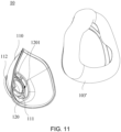
- FIG. 11 shows a three-dimensional schematic diagram of a cushion assembly in an exploded state
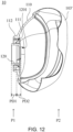
- FIG. 12 shows a section schematic diagram of the cushion assembly in FIG. 11 in an assembled state
- the cushion assembly 10 includes a hollow structure 110, a cylindrical wall 120 and a seal assembly 103'.
- the hollow structure 110 has a central aperture 111 and a protruding structure 112.
- the central aperture 111 is structured on a first end P1 of the cushion assembly 10, and provides a route for delivering an air flow when the patient interface is in use.
- the protruding structure 112 is structured to project from the central aperture 111 in a direction towards the first end P1 of the cushion assembly 10.
- the cylindrical wall 120 is provided to the central aperture 111.
- the cylindrical wall 120 is structured as substantially concentric with the central aperture 111.
- the cylindrical wall 120 projects in a manner of having a same diameter towards the first end P1 of the cushion assembly 10 by a first distance PD1, and projects in a manner of having different diameters towards a second end P2 opposite to the first end P1 of the cushion assembly 10 by a second distance PD2.
- a diameter change within the second distance PD2 may be that the diameter substantially decreases in a direction towards the second end P2; in contrast, a diameter change within the first distance PD1 may be that the diameter substantially stays constant in a direction towards the first end P1. Moreover, in other embodiments, the first distance PD1 may be greater than the second distance PD2.
- an eaves portion 1201 having a gradually decreasing diameter in a direction towards the second end P2 may be configured only on a part of an end portion of the cylindrical wall 120, further appearing as a partially encircling eaves portion 1201 of less than 360 degrees. It is observed from FIG. 12 that, under a vertical section line of the partially encircling eaves portion 1201, a partial position at a lower portion of the cylindrical wall 120 does not include the eaves portion 1201. However, when another section line (not shown) perpendicular to the section line in FIG. 12 is used, the eaves portions are present on both upper and lower sides of the cylindrical wall 120.
- the example shown in FIG. 12 is an eaves portion that encircles by 270 degrees on the end portion of the cylindrical wall 120.
- FIG. 13 shows a three-dimensional schematic diagram of a cushion assembly
- FIG. 14 shows a section schematic diagram of the cushion assembly in FIG. 13
- the cushion assembly 10 includes a hollow structure 110, a cylindrical wall 120 and a seal assembly 103'.
- the hollow structure 110 has a cylindrical orifice 111' and a first protruding structure 112'.
- the cylindrical orifice 111' is structured on a first end P1 of the cushion assembly 10, and is for delivering an air flow when the patient interface is in use.
- the first protruding structure 112' is structured to project from the cylindrical orifice 111' in a direction towards the first end P1 of the cushion assembly 10.
- the cylindrical wall 120 is provided to the cylindrical orifice 111'.
- the cylindrical wall 120 is structured as substantially concentric with the cylindrical orifice 111'.
- the cylindrical wall 120 has a second protruding structure 122 and a third protruding structure 123.
- the second protruding structure 122 projects towards the first end P1 of the cushion assembly 10, and the third protruding structure 123 projects towards a second end P2 opposite to the first end P1 of the cushion assembly 10.
- the first protruding structure 112' and the second protruding structure 122 are formed as concentric.
- a diameter D2 of the second protruding structure 122 is smaller than a diameter D1 (an inner diameter as an example in FIG. 14 ) of the first protruding structure 112'.
- the third protruding structure 123 has a first section 1231 and a second section 1232.
- the first section 1231 appears as a stalk form
- the second section 1232 appears as a head form that is supported by the first section 1231.
- the first section 1231 in a stalk form is provided on the cylindrical wall 120 and is in flow communication with the cylindrical orifice 111'.
- the head of the second section 1232 is substantially truncated hollow cone, and has a relatively narrow top end so as to extend into the hollow structure 110.
- the eaves portion encircling by 360 degrees in form of a truncated hollow cone is shown in the exemplary embodiments in FIG. 13 and FIG. 14 .
- the second section 1232 appearing as a truncated hollow cone has a diameter smaller than the diameter D2 (an inner diameter as an example in FIG. 14 ) of the second protruding structure 122.
- D2 an inner diameter as an example in FIG. 14
- the first to third protruding structures they may also be referred to as first to third protruding ring structures, wherein the hollow structure 110 may be formed by a single material.
- a seal assembly 103' is configured to be in a soft material relative to the hollow structure 110.
- the first section 1231 in a stalk form may be regarded as a support structure, such that the cylindrical wall 120 can be provided to an opening part (the cylindrical orifice 111') of the hollow structure 110 and be concentric with the opening part (the cylindrical orifice 111').
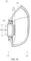
- FIG. 15 shows a section schematic diagram of a cushion assembly.
- An inner diameter of the cylindrical wall 120 before a change is an initial diameter D21
- the inner diameter of the cylindrical wall 120 after the change is a reduced diameter D22.
- the cylindrical wall 120 extends into the hollow structure 110 by an extent of a depth D4.
- a distance by which the cylindrical wall 120 changes from the initial diameter D21 to the reduced diameter D22 is longer, and the cylindrical wall 120 can be extended more into the hollow structure 110.
- the cylindrical wall 120 in FIG. 15 has a more moderate change in the diameter and extends into the hollow structure 110 by a deeper extent.
- an inner wall surface of the cylindrical wall 120 may exhibit a more moderate curved surface or inclined surface.
- FIG. 16 shows a three-dimensional schematic diagram of a headgear assembly
- FIG. 17 shows a schematic diagram of the headgear assembly in FIG. 16 worn at a head of a patient.
- the headgear assembly 20 includes a plurality of straps, and these straps are for adjusting the position of the patient interface when the patient interface is worn by a patient, allowing the patient interface to be stably and comfortably secured at the head of the patient, and to form an air flow space, breathing chamber or inflating chamber on a face of the patient to apply a treatment pressure to airways of the patient.
- These straps include a plurality of upper straps 210, a plurality of lower straps 220, and a rear portion configured to reach at least a part of an occipital bone of the patient when in use, wherein the rear portion is referred to as a rear strap assembly 230.
- the upper straps 210 include straps extendable to above ears of the applying patient, and the lower straps 220 include straps extendable to below the ears of the applying patient (referring to FIG. 17 ).
- the rear strap assembly 230 includes a top portion 231, a plurality of side portions 232 and a bottom portion 233.
- the frame assembly 50 is adapted to correspond to the attachment of the upper straps 210, and a position of the attachment is, for example, the slits 501 of the frame assembly 50 and located on upper edges of two sides.
- the frame assembly 50 is adapted to correspond to the attachment of the lower straps 230, and a position of the attachment is, for example, the lower straps 220 correspondingly attached by the corresponding headgear clips 30 engaged with the slits 501 at lower edges on the two sides of the frame assembly 50.
- the top portion 231 of the rear strap assembly 230 is provided between the side portions 232, and the bottom portion 233 of the rear strap assembly 230 is provided between the side portions 232 and the lower straps 220.
- the bottom portion 233 of the rear strap assembly 230 may be simultaneously connected to the side portions 232 and the lower straps 230, and the upper straps 210 are provided on one side corresponding to the side portions 232.
- the upper straps 210 include upper strap attaching portions 211 on ends connected to the corresponding side portions 232, and the lower straps 220 include lower strap attaching portions 221 on ends opposite to the ends connected to the corresponding lower portion 233.
- the upper strap attaching portions 211 and the lower strap attaching portions 221 are secured on the frame assembly 50 and/or secured on the headgear clips 30 by means of attachment.
- the upper strap attaching portions 211 and the lower strap attaching portions 221 are, for example, parts with felting effects, such as hook-and-eye straps (for fastening to surfaces of the upper straps 210 or the lower straps 220).
- each of the side portions 232 has an intersection point f.
- a first strap distance d1 between the intersection point f of each side portion 232 and the lower portion 233 is a second strap distance d2
- a third strap distance d3 between the intersection point f of each side portion and the upper strap 210 is a third strap distance d3.
- the first strap distance d1 is smaller than the second strap distance d2, and in another implementation aspect, the first strap distance d1 is also greater than the third strap distance d3.
- each side portion 232 is a geometric center of the side portion.
- each side portion 232 has a junction from the top portion 231, the upper straps 210 and the lower portion 233, and three perpendicular segments from the intersection point f to the junction may commonly intersect at the intersection point f.
- the pressure imposed by the headgear assembly 20 on the head of a wearer or a patient can be appropriately distributed to improve wearing comfort.
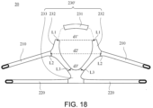
- FIG. 18 shows a three-dimensional schematic diagram of a headgear assembly.
- the headgear assembly 20 includes a plurality of straps, and these straps are for adjusting the position of the patient interface when the patient interface is worn by a patient.
- These straps include a plurality of upper straps 210, a plurality of lower straps 220, and a rear portion 230' configured to reach at least a part of an occipital bone of the patient when in use.
- the rear strap assembly 230' includes a top portion 231, a plurality of side portions 232 and a bottom portion 233.
- the top portion 231 is provided between the side portions 232
- the bottom portion 233 is provided between the side portions 232 and the lower straps 220
- the upper straps 210 are provided to the corresponding side portions 232.
- Between each side portion 232 and the top portion 231 is a engaging line l1, between each upper strap 210 and the corresponding side portion 232 is a second engaging line L2, and between each side portion 232 and the bottom portion 233 is a third engaging line L3.
- a distance between centers of two first engaging lines L1 is a first strap gap d1'.
- a distance between centers of two second engaging lines L1 is a second strap gap d2'.
- a distance between centers of two third engaging lines L1 is a third strap gap d3'.
- the first strap gap d1' is smaller than the second strap gap d2' and greater than the third strap gap d3'.
- FIG. 19 shows a three-dimensional schematic diagram of an elbow assembly and a transition ring structure in an exploded state
- FIG. 20 shows a section schematic diagram of the elbow assembly and the transition ring structure in FIG. 19 in an assembled state.
- the elbow assembly 40 is provided to the transition ring structure 410, and is rotatable by 360 degrees relative to the elbow assembly 40.
- the elbow assembly 40 includes a first end 41, a second end 42 and a body 43.
- the body 43 of the elbow assembly 40 includes a conduit air pathway capable of adjusting a direction of an air flow.
- the body 43 defines, by a bent inner wall, the conduit air pathway producing a turning effect on the air flow being delivered, further generating a route adjustment effect on the air flow flowing through the elbow assembly 40.
- the air flow (referring to FIG.1 ) delivered from the flow generator (not shown) through the air delivery tube 60 enters the elbow assembly 40 through the second end 42 of the elbow assembly 40, passes through the conduit air pathway in the body 43 of the elbow 43 to cause a change in the delivery direction of the air flow, and is then discharged from the first end 41 to form the route of the air flow delivered towards the air flow space, breathing chamber or inflating chamber as described above.
- FIG. 21 shows a section schematic diagram of the elbow assembly and the transition ring structure in FIG. 19 in an assembled state from another perspective.
- a curved outer structure of the first end 41 of the elbow assembly 40 may included a plurality of concavities 411 formed on an outer surface of the first end 41.
- the concavities 411 and at least a part of the transition ring structure 510 may together form air pathways 44 (or referred to as exhaust ducts). As shown in FIG.
- the concavities 411 and an inner wall surface of the transition ring structure 510 together form passages for air to pass through, and these passages are in communication with the air flow space, breathing chamber or inflating chamber above, further allowing air exhaled by the patient to be discharged through the passages to the ambient environment.
- an outer surface of the first end 41 of the elbow assembly 40 may further include ring groove 412 and a blocking portion 413.
- the ring groove 412 is structured to encircle on the outer surface of the first end 41, and crosses the concavities 411.
- the ring groove 412 is structured to match with the inner surface of the transition ring structure 510.
- FIG. 22 shows a schematic diagram of a patient interface according to another embodiment of the present invention
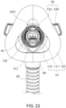
- FIG. 23 shows a three-dimensional schematic diagram of a patient interface in FIG. 22 from another perspective.
- the cylindrical wall 120 is provided in the cylindrical orifice 111' of the cushion assembly 10 by a plurality of support structures 1021, wherein the support structures 1021 are in flow communication with the cylindrical orifice 111'.
- One end of each of the support structures 1021 is connected to the outer surface of the cylindrical wall 120, and the other end of each of the support structures 1021 is connected to the inner surface of the cylindrical orifice 111' (referring to FIG. 13 and FIG. 14 ).
- the support structures 1021 are in an asymmetric arrangement relative to an axis of the cylindrical wall 120, wherein the axis is a central axis (a vertical line perpendicular to the drawing) of the cylindrical wall 120.
- the asymmetrical arrangement of the support structures 1021 are, for example, an arrangement in which two adjacent support structures 1021 with a shortest gap in between along the outer surface of the cylindrical wall 120 can correspond to positions of a nose of the patient wearing the patient interface in use.
- the transition ring structure 510 provides attachment of the headgear secure assembly 520, the elbow assembly 40 and the cushion assembly 10, and allows the headgear secure assembly 520, the elbow assembly 40 and the cushion assembly 10 to have a non-direct engagement relation.
- the elbow assembly 40 is used for outputting air to an end portion of the first end 41 via the transition ring structure 510, and can coordinate with one end of the cylindrical wall 120 of the cushion assembly 10 to form an air duct for passing and delivering an air flow to a rear end. Gas exhaled by the patient may be guided to the air pathways 44 (referring to FIG. 23 ) for gas washout, so as to form a state of flow field diversion of the air flow.
- the elbow assembly defines, by the bent inner wall, a conduit air pathway that causes most of a delivered air flow g to be gathered on an upper portion. Most of the incoming air flow delivered from the flow generator to the breathing chamber may pass through the conduit air pathway and the inner surface of the cylindrical wall 120 of the cushion assembly 10.
- An eaves structure on the other end of the cylindrical wall 120 further provides the flow field of the air flow with guidance. The eaves structure (a part projecting towards the second end of the cushion assembly 10) of the cylindrical wall 120 can change the direction of outgoing air flow for the air flow delivered from the elbow assembly 40, such that the direction of the outgoing air flow is adjusted downwards.
- the eaves structure of the cylindrical wall 120 causes a main air flow mostly gathered on the upper portion of the conduit air pathway to exit from the cylindrical wall 120 in an outgoing direction that non-parallel to the axis of the cylindrical wall 120. Therefore, the degree of impact imposed by the air flow on the mouth and nose of the patient can be alleviated, and the air flow exhaled by the patient when in use is enabled to smoothly flow to the upper portion of the air flow space, breathing chamber or inflating chamber and further be discharged via the air pathways (exhaust ducts) to the ambient environment.
- the headgear assembly 20 is secured in the patient interface by the headgear secure assembly 520 and the headgear clips 30.
- the headgear attachment portions 522 of the headgear secure assembly 520 are for attaching the corresponding headgear clips 30, and the straps corresponding to the headgear assembly 20 are then secured to the headgear secure assembly 520 by the headgear clips 30.
- the upper opening 521 of the headgear secure assembly 520 is for attaching the corresponding strap of the headgear assembly 20.
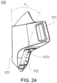
- the headgear attachment portion 522 has an attachment pin 5221, which can be used for attaching the corresponding headgear clip 30.
- a center axis of the attachment pin 5221 forms an inclined angle ⁇ 1 relative to the opening plane.
- the inclined angle ⁇ 1 that is, an included angle of the opening plane formed relative to the central opening 523 in a clockwise direction, can be between 18 and 22 degrees, and preferably is configured at an angle between 20.5 and 20.7 degrees.
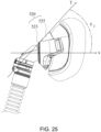
- the headgear secure assembly 520 includes an upper cover 525 extended in a direction oblique from the central opening 523 towards a rear end.
- the upper cover 525 is in a lifted manner, and a lifted angle ⁇ 2 formed by such degree of lifting between a tangent T of the upper cover 525 and a center axis X of the central opening 523 is between 42 and 48 degrees.
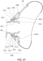
- FIG. 26 shows a three-dimensional schematic diagram of a connecting ring structure
- FIG. 27 shows a section schematic diagram of the connecting ring structure in FIG. 26 in a state of use
- FIG. 28 shows a three-dimensional schematic diagram of the connecting ring structure in FIG. 26 in a state of use
- a connecting ring structure 510' (or referred to as a transition ring structure) has a first ring portion 511 and a second ring portion 512.
- An inner diameter of the first ring portion 511 is greater than an inner diameter of the second ring portion 512.
- An outer diameter of the first ring portion 511 is also greater than an outer diameter of the second ring portion 512.
- the connecting ring structure 510' has a first limiting portion 514, which correspondingly interferes a second limiting portion 524 on the headgear secure assembly 520.
- a width of the first limiting portion 514 is slightly greater than a width of the second limiting portion 524, such that the headgear secure assembly 520 and the connecting ring structure 510' are rotatable relative to each other within a limit.
- the interference structure 513 and a bottom edge of the first limiting portion, and a transition surface 515 between the first ring portion 511 and the second ring portion 512 the headgear secure assembly 520 is held on the connecting ring structure 510'.
- the transition surface 515 is, for example, an inclined surface, and can match with the inner surface of the headgear secure assembly 520, so as to further press the headgear secure assembly 520 between the transition surface 515 and the interference structure 513.
- the first ring portion 511 has a channel 516 extended on a surface of an outer periphery thereof.
- the channel 516 may be used for fitting with a stop portion 1014 on the ring structure 1011 of the cushion assembly 10.
- the first ring portion 511 and the cushion assembly 10 may be engaged by means of snapfit connection in between.
- the stop portion 1014 may be, for example, a ridge close to the first end of the cushion assembly 10.
- the stop portion 1014 may be correspondingly positioned in the channel 516 of the first ring portion 511.
- the ridge is rotatable and mobile along a path of the channel in the channel 516, such that the cushion assembly 10 is rotatable relative to the connecting ring structure 510' to a certain extent after the cushion assembly 10 is engaged with the connecting ring structure 510'.
- an outer diameter of the first ring portion 511 gradually decreases from an intersection between the first ring portion 511 and the second ring portion 522 in a direction towards the cushion assembly 10, such that a wall thickness of the first ring portion 511 decreases in a direction from the middle of the connecting ring structure 510' towards the cushion assembly 10. Accordingly, when the cushion assembly 10 is engaged, the first ring portion 511 provides a small amount of deformation to facilitate the stop portion 1014 on the ring structure 1011 of the cushion assembly 10 to reach the channel 516 on the first ring portion 511.
- the elbow assembly 40 and the headgear secure assembly 520 are respectively attached to inner and outer sides of the connecting ring structure 510'.
- the second ring portion 520 in use is configured between the headgear secure assembly 520 and the elbow assembly 40. After the assembly, the elbow assembly 40 and the headgear secure assembly 520 are not physically in contact in between.
- the second ring portion 512 may additionally have an inner flange 517 axially projecting inwards on an inner side thereof. With respect to the engaging of the elbow assembly 40 and the connecting ring structure 510', the inner flange 517 may be accommodated in the ring groove 412 of the elbow assembly 40.
- the elbow assembly 40 is rotatably attached to the connecting ring structure 510'.
- the elbow assembly 40 is connected in a non-detachable manner to the connecting ring structure 510'.
- the elbow assembly 40 may have a blocking portion 413 on one end thereof.
- the blocking portion 413 is for blocking the step portion 518 at the boundary between the first ring portion 511 and the second ring portion 512 to provide a blocking effect, so that the elbow assembly 40 can be more stable during a rotation.
- the blocking effect prevents the elbow assembly 40 from being removed from the connecting ring structure 510' from an outer side.
- FIG. 29 showing a section schematic diagram of a cylindrical wall of a cushion assembly.
- the structural shape of the cylindrical wall 120 in the cushion assembly 10 provides an air flow flowing through with a guiding effect, further producing a change in an exit direction for the air flow flowing through and exiting the cylindrical wall 120.
- the structural shape of the cylindrical wall 120 provides the air flow passing through the elbow assembly 40 and turned and deflected with an excellent guiding effect, as shown in FIG. 21 .
- the diameter of the cylindrical wall 120 is reduced towards one end of the cushion assembly 10 according to a reduction rate.
- the inner diameter of the cylindrical wall 120 before the change is the initial diameter D21
- the inner diameter of the cylindrical wall 120 after the change is the reduced diameter D22
- a change segment D3 refers to a length of the cylindrical wall 120 with a reduction change in an axial direction of the center axis X of the cylindrical wall 120.
- the reduction rate refers to that, within the length of the change segment D3, the diameter of the cylindrical wall 120 is changed from the initial diameter D21 by 5% to 25% to become the diameter D22, and the length of the change segment D3 does not exceed 10 mm.
- the reduction rate reduces the diameter of the cylindrical wall 120 by 7.5% to 22.5% within the change segment D3 having a length of 8 mm.
- the reduction rate reduces the diameter of the cylindrical wall 120 by 10% to 20% within the change segment D3 having a length of 6 mm.
- a ratio of an opening area of an opening at an air flow inlet end of the cylindrical wall 120 to an opening area of an opening at an air flow outlet end of the cylindrical wall 120 is between 0.5 and 0.95.
- the opening area of the opening at an air flow inlet end of the cylindrical wall 120 is based on the size of the initial diameter D21, and the opening area of the opening at the air flow outlet end of the cylindrical wall 120 is based on the reduced diameter D22.
- the cylindrical wall 120 has an extension segment D4 projecting from an end edge of the ring structure 1011 of the cushion assembly 10 in a direction parallel to the center axis X, and a distance of the extension segment D4 is preferably 1 mm to 10 mm.
- the extension segment D4 substantially extends into the air flow space, breathing chamber or inflating chamber above.
- the cylindrical wall 120 having a guiding effect is capable of alleviating the level of impact imposed by an outgoing air flow upon the mouth and nose of the patient.
- a flow diversion effect is at the same time provided for an incoming air flow field and an outgoing air flow filed, further enabling the air flow exhaled by the patient when in use to smoothly flow to the air flow space, breathing chamber or inflating chamber and further be discharged to the ambient environment via the air pathways (exhaust ducts) 44 shown in FIG. 21 and FIG. 23 .
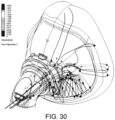
- FIG. 30 shows an analysis diagram of a flow field disclosed according to an embodiment of the present disclosure
- FIG. 31 shows an analysis diagram of a flow field disclosed according to another embodiment of the present disclosure
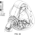
- FIG. 32 shows an analysis diagram of a flow field disclosed according to yet another embodiment of the present disclosure.
- FIGS. 30 to 32 show flow fields of air flows flowing in the air flow space, breathing chamber or inflating chamber described above.
- the analysis diagram of the flow field shown in FIG. 30 relates to a situation where an end portion of a cylindrical wall of a patient interface has an eaves portion encircling by 60 degrees (also referring to the eaves portion encircling by 270 degrees shown in FIG. 12 ).
- the analysis diagram of the flow field shown in FIG. 31 relates to a situation where an end portion of a cylindrical wall of a patient interface has an eaves portion encircling by 270 degrees.
- the analysis diagram of the flow field shown in FIG. 32 relates to a situation where an end portion of a cylindrical wall of a patient interface has an eaves portion encircling by 360 degrees.
- FIG. 30 flow field guidance is obviously present along the hollow structure and the inner wall surface of the seal assembly in the breathing chamber. Moreover, obvious guiding air flows flowing to the air pathways (exhaust ducts) are produced at the upper portion of the breathing chamber. In FIG. 31 , guiding air flows flowing to the air pathways (exhaust ducts) at the upper portion of the breathing chamber are even more obvious. In FIG. 32 , guiding air flows flowing to the air pathways (exhaust ducts) are further reinforced. Therefore, with the patient interface that uses a cushion assembly with a cylindrical wall, a flow diversion effect for an incoming air flow field and an outgoing air flow field is emphasized, and noise is also improved while smooth flow fields are provided.
- the seal forming assembly 140 shown in FIG. 6 is adapted to seal a face of a patient in response to wearing of the patient. Distribution positions of support areas in the seal forming assembly 140 provide further improvement with respect to the wearing comfort of the wearer and the securing stability on the face of the patient. Moreover, the headgear assembly 20 shown in FIG. 16 and FIG. 18 provide excellent multiplied effects in aspects of stably securing the patient interface with comfort on the face of the patient.
Landscapes
- Health & Medical Sciences (AREA)
- Heart & Thoracic Surgery (AREA)
- Life Sciences & Earth Sciences (AREA)
- Engineering & Computer Science (AREA)
- Anesthesiology (AREA)
- Biomedical Technology (AREA)
- Emergency Medicine (AREA)
- Hematology (AREA)
- Pulmonology (AREA)
- Animal Behavior & Ethology (AREA)
- General Health & Medical Sciences (AREA)
- Public Health (AREA)
- Veterinary Medicine (AREA)
- Orthopedics, Nursing, And Contraception (AREA)
- Devices For Medical Bathing And Washing (AREA)
Claims (16)
- Patientenschnittstelle zur Therapie mit kontinuierlich positivem Atemwegsdruck (CPAP), welche Folgendes umfasst:eine Polsteranordnung (10), welche Folgendes umfasst:eine Abschirmung (101), die eine Öffnung, die an einem ersten Ende der Polsteranordnung strukturiert ist, und eine Ringstruktur (1011), die von der Öffnung in Richtung zum ersten Ende der Polsteranordnung (10) vorsteht, aufweist,eine zylindrische Wand (120), die an der Öffnung durch eine Vielzahl von Stützstrukturen (1021) bereitgestellt ist und konzentrisch mit der Öffnung ausgebildet ist, wobei die zylindrische Wand (120) so vorsteht, dass sie unterschiedliche Durchmesser in zwei entgegengesetzten Richtungen entlang einer Achse der Öffnung aufweist, undeine Dichtungsanordnung (103), die an der Abschirmung (101) der Polsteranordnung (10) vorgesehen ist und zusammen damit eine Atemkammer bildet, wobei die Dichtungsanordnung (103) dafür ausgelegt ist, ein Gesicht eines Patienten abzudichten,eine Kopfbandanordnung (20), die eine Vielzahl von Bändern zur Befestigung der Patientenschnittstelle bei der Verwendung umfasst,eine Ellbogenanordnung (40), die dafür ausgelegt ist, in Fluidverbindung mit der Polsteranordnung zu stehen, um bei der Verwendung einen Luftstrom zu den Atemwegen des Patienten zu leiten,eine Verbindungsringstruktur (510'), deren eines Ende mit der Polsteranordnung (10) und deren anderes Ende unlösbar mit der Ellbogenanordnung (40) verbunden ist, undeine Kopfband-Sicherungsanordnung (520), die dafür ausgelegt ist, in die Verbindungsringstruktur (510') einzugreifen, wobei die Kopfband-Sicherungsanordnung (520) eine Vielzahl von Schlitzen aufweist, die so ausgelegt sind, dass sie bei der Verwendung an den entsprechenden Bändern befestigt werden, wobei die Kopfband-Sicherungsanordnung nicht mit einer Stirnstütze versehen ist.
- Patientenschnittstelle nach Anspruch 1, wobei die zylindrische Wand (120) mit gleichem Durchmesser in Richtung des ersten Endes (P1) der Polsteranordnung (10) um einen ersten Abstand (PD1) vorsteht, die zylindrische Wand (120) mit abnehmendem Durchmesser in Richtung des zweiten Endes (P2), das dem ersten Ende (P1) der Polsteranordnung (10) gegenüberliegt, um einen zweiten Abstand (PD2) vorsteht und der erste Abstand (PD1) größer als der zweite Abstand (PD2) ist.
- Patientenschnittstelle nach Anspruch 2, wobei die zylindrische Wand (120) mit abnehmendem Durchmesser in Richtung des zweiten Endes (P2) der Polsteranordnung (10) vorsteht, um einen Kopf mit einem im Wesentlichen abgestumpften Hohlkegel zu bilden, und der Kopf ein relativ schmales oberes Ende hat, um in die Abschirmung (101) einzutreten.
- Patientenschnittstelle nach Anspruch 1, wobei die Verbindungsringstruktur (510') und die Polsteranordnung (10) im befestigten Zustand dazwischen drehbar sind.
- Patientenschnittstelle nach Anspruch 1, wobei die Abschirmung (101) und die Dichtungsanordnung (103) einstückig geformt sind.
- Patientenschnittstelle nach Anspruch 1, wobei die Polsteranordnung (10), die Ellbogenanordnung (40) und die Kopfbandsicherungsanordnung (520) bei der Verwendung direkten physischen Kontakt oder physisches Eingreifen ausschließen.
- Patientenschnittstelle nach Anspruch 1, wobei die Stützstrukturen (1021) als Stängel geformt sind, jede der Stützstrukturen (1021) ein Ende, das mit einer Außenfläche der zylindrischen Wand (120) verbunden ist, und ein anderes Ende, das mit einer Innenfläche der Öffnung der Abschirmung (101) verbunden ist, hat, und die Stützstrukturen (1021) in einer asymmetrischen Anordnung in Bezug auf eine Achse der zylindrischen Wand (120) ausgebildet sind.
- Patientenschnittstelle nach Anspruch 7, wobei die Ellbogenanordnung (40) eine Vielzahl von Konkavitäten (411) umfasst, die an einer Außenfläche eines ersten Endes der Ellbogenanordnung (40) vorgesehen sind, wobei die Vielzahl von Konkavitäten (411) und eine Innenfläche der Verbindungsringstruktur (510') zusammen eine Vielzahl von Abluftkanälen bilden, wenn das erste Ende der Ellbogenanordnung (40) mit der Verbindungsringstruktur (510') in Eingriff ist, wobei die Abluftkanäle dazu dienen, dass ein aus der Atemkammer in die Umgebung austretender Luftstrom durch sie hindurch fließt, die Stützstrukturen (1021) in Strömungsverbindung mit den Abluftkanälen stehen und zwei benachbarte der Stützstrukturen (1021) mit einem kürzesten Abstand dazwischen entlang einer Außenfläche der zylindrischen Wand (120) einer Nase eines Patienten entsprechen, der die Patientenschnittstelle trägt.
- Patientenschnittstelle nach Anspruch 8, wobei die Ellbogenanordnung (40) einen Körper (43) umfasst, wobei der Körper (43) durch eine gebogene Innenwand einen Leitungsluftweg definiert, der bewirkt, dass der größte Teil eines zugeführten Luftstroms an einem oberen Abschnitt gesammelt wird, wobei ein Abschnitt der zylindrischen Wand (120), der in Richtung eines zweiten Endes gegenüber dem ersten Ende der Polsteranordnung (10) vorsteht, eine Richtung eines abgehenden Luftstroms für den von der Ellbogenanordnung (40) zugeführten Luftstrom ändert, so dass ein Hauptluftstrom, der hauptsächlich am oberen Abschnitt des Leitungsluftwegs gesammelt wird, die zylindrische Wand in einer Ausgangsrichtung verlässt, die nicht parallel zu einer Achse der zylindrischen Wand (120) ist, um ein Maß an Aufprall, das durch den Luftstrom auf den Mund und die Nase des Patienten ausgeübt wird, zu vermindern, und ein Luftstrom, der durch den Patienten ausgeatmet wird, wenn er im Gebrauch ist, in die Lage versetzt wird, reibungslos zu einem oberen Abschnitt der Atemkammer zu strömen und weiter über die Auslasskanäle in die Umgebung abgeleitet zu werden.
- Patientenschnittstelle nach Anspruch 1, wobei ein Durchmesser der zylindrischen Wand (120) in Richtung eines zweiten Endes (P2), das dem ersten Ende (P1) der Polsteranordnung (10) gegenüberliegt, mit einer Reduktionsrate abnimmt, und die Reduktionsrate den Durchmesser der zylindrischen Wand (120) innerhalb einer Länge von 5 mm bis 10 mm um 5 % bis 25 % reduziert.
- Patientenschnittstelle nach Anspruch 1, wobei ein Verhältnis einer Öffnungsfläche einer Öffnung der zylindrischen Wand (120), die dem ersten Ende (P1) der Polsteranordnung (10) zugewandt ist, zu einer Öffnungsfläche einer Öffnung der zylindrischen Wand (120), die einem zweiten Ende (P2) gegenüber dem ersten Ende (P1) der Polsteranordnung (10) zugewandt ist, 0,5 bis 0,95 ist, und eine Länge, um die sich ein Abschnitt der zylindrischen Wand (120), der in Richtung des zweiten Endes (P2) der Polsteranordnung (10) vorsteht, in die Atemkammer in einer Richtung parallel zu einer Achse der zylindrischen Wand (120) erstreckt, größer als 1 mm ist.
- Patientenschnittstelle nach Anspruch 1, wobei die Verbindungsringstruktur (510') einen ersten Ringabschnitt (511) und einen zweiten Ringabschnitt (512) umfasst, ein Innendurchmesser des ersten Ringabschnitts (511) größer als ein Innendurchmesser des zweiten Ringabschnitts (512) ist, der erste Ringabschnitt (511) und die Polsteranordnung (10) mittels einer Schnappverbindung miteinander in Eingriff sind, der zweite Ringabschnitt (512) so strukturiert ist, dass er zwischen der Kopfband-Sicherungsanordnung (520) und der Ellbogenanordnung (40) konfiguriert ist, wenn sie im Gebrauch sind, und die Verbindungsringstruktur (510') bewirkt, dass die Polsteranordnung (10) und die Ellbogenanordnung (40) nicht in direktem physischen Kontakt oder physischem Eingriff sind, wenn sie im Gebrauch sind.
- Patientenschnittstelle nach Anspruch 12, wobei der erste Ringabschnitt (511) einen sich erstreckenden Kanal (516) umfasst, der Kanal (516) für einen Anschlagabschnitt (1014) an der Ringstruktur (1011) der Polsteranordnung (10) zur Durchführung der Befestigung bestimmt ist, der zweite Ringabschnitt (512) an seiner Endkante eine radial nach außen vorstehende Interferenzstruktur (513) aufweist, die Interferenzstruktur (513) bewirkt, dass die Verbindungsringstruktur (510') an einer zentralen Öffnung (523) der Kopfband-Sicherheitsanordnung (520) befestigt wird, der zweite Ringabschnitt (512) an seiner Innenseite einen inneren Flansch (517) aufweist, der radial nach innen vorsteht, der innere Flansch (517) so strukturiert ist, dass er in einer Ringnut (412) an der Ellbogenanordnung (40) aufgenommen wird, wenn sie im Gebrauch ist, die Ellbogenanordnung (40) an einem Ende davon einen Blockierabschnitt (413) aufweist, der Blockierabschnitt (413) so strukturiert ist, dass er an einer Grenze zwischen dem ersten Ringabschnitt (511) und dem zweiten Ringabschnitt (512) anhält, die Verbindungsringstruktur (510') einen ersten Begrenzungsabschnitt (514) aufweist, der erste Begrenzungsabschnitt (514) so strukturiert ist, dass er einem zweiten Begrenzungsabschnitt (524) an der Kopfband-Sicherheitsanordnung (520) entspricht und in diesen eingreift, wenn er im Gebrauch ist, eine Breite des ersten Begrenzungsabschnitts (514) etwas größer als eine Breite des zweiten Begrenzungsabschnitts (524) ist, um einen Drehwinkel zwischen der Kopfband-Sicherheitsanordnung (520) und der Polsteranordnung (10) bereitzustellen, und ein Außendurchmesser des ersten Ringabschnitts (511) allmählich von der Grenze des ersten Ringabschnitts (511) und des zweiten Ringabschnitts (512) in einer Richtung zum zweiten Ende der Polsteranordnung (10) abnimmt.
- Patientenschnittstelle nach Anspruch 1, wobei die Dichtungsbildungsanordnung (140) einen ersten Stützbereich (141), der an der Abschirmung (101) vorgesehen ist, und einen zweiten Stützbereich (142), der sich von dem ersten Stützbereich (141) aus erstreckt, umfasst, wobei eine Grenze (144) zwischen dem ersten Stützbereich (141) und dem zweiten Stützbereich (142) ausgebildet ist, wobei eine Position, an der sich die Dichtungsbildungsanordnung von einer Grenze zwischen der Abschirmung und dem ersten Stützbereich (141) aus erstreckt und die Dicke allmählich auf eine vorbestimmte Dicke abnimmt, als die Grenze (144) definiert ist, und wobei die vorbestimmte Dicke ein beliebiger Wert ist, der aus einem Bereich zwischen 0,50 mm und 0,70 mm ausgewählt wird.
- Patientenschnittstelle nach Anspruch 1, wobei die Dichtungsbildungsanordnung (140) einen ersten Stützbereich (141), der an der Abschirmung (101) vorgesehen ist, und einen zweiten Stützbereich (142), der sich von dem ersten Stützbereich (141) erstreckt, umfasst, wobei eine erste Grenze zwischen der Abschirmung (101) und dem ersten Stützbereich (141) gebildet ist, wobei eine zweite Grenze (142) zwischen dem ersten Stützbereich (141) und dem zweiten Stützbereich (142) gebildet ist, eine Position, an der sich die Dichtungsbildungsanordnung (140) von der ersten Grenze erstreckt und die Dicke allmählich auf eine vorbestimmte Dicke abnimmt, als die zweite Grenze definiert ist, zwischen einer Position jedes Punkts auf der ersten Grenze und der zweiten Grenze ein vertikaler Abstand besteht, und unter den vertikalen Abständen die entsprechenden vertikalen Abstände in der Nähe von Wangen und Wangenknochen des Patienten, wenn im Gebrauch, größer sind als die entsprechenden vertikalen Abstände in der Nähe einer Nase und eines Kinns des Patienten, wenn im Gebrauch.
- Patientenschnittstelle nach Anspruch 1, wobei die Kopfbandanordnung (20) eine Vielzahl von oberen Bändern (210) und eine Vielzahl von unteren Bändern (220) zur Einstellung der Position umfasst und einen hinteren Abschnitt (230) umfasst, der so konfiguriert ist, dass er im Gebrauch mindestens einen Teil eines Hinterhauptbeins eines Patienten erreicht, wobei der hintere Abschnitt (230) einen oberen Abschnitt (231), eine Vielzahl von Seitenabschnitten (232) und einen unteren Abschnitt (233) umfasst, wobei der obere Abschnitt (231) zwischen den Seitenabschnitten (232) bereitgestellt ist, der untere Abschnitt (233) zwischen den Seitenabschnitten (232) und den unteren Bändern (220) bereitgestellt ist, die Vielzahl von oberen Bändern (210) an den entsprechenden Seitenabschnitten (232) bereitgestellt sind, zwischen jedem der Seitenabschnitte (232) und dem oberen Abschnitt (231) eine erste Eingriffslinie (L1) ist, zwischen jedem der oberen Bänder (210) und dem entsprechenden Seitenabschnitt (232) eine zweite Eingriffslinie (L2) ist, zwischen jedem der Seitenabschnitte (232) und dem unteren Abschnitt (233) eine dritte Eingriffslinie (L3) ist, ein Abstand zwischen den Zentren der beiden ersten Eingriffslinien (L1) ein erster Bandabstand (d1') ist, ein Abstand zwischen den Zentren der beiden zweiten Eingriffslinien (L2) ein zweiter Bandabstand (d2') ist, ein Abstand zwischen den Zentren der beiden dritten Eingriffslinien (L3) ein dritter Bandabstand (d3') ist, und der erste Bandabstand (d1') kleiner als der zweite Bandabstand (d2'), jedoch größer als der dritte Bandabstand (d3') ist.
Applications Claiming Priority (1)
| Application Number | Priority Date | Filing Date | Title |
|---|---|---|---|
| TW110107046A TWI770844B (zh) | 2021-02-26 | 2021-02-26 | 患者介面 |
Publications (2)
| Publication Number | Publication Date |
|---|---|
| EP4049702A1 EP4049702A1 (de) | 2022-08-31 |
| EP4049702B1 true EP4049702B1 (de) | 2023-05-03 |
Family
ID=80953479
Family Applications (1)
| Application Number | Title | Priority Date | Filing Date |
|---|---|---|---|
| EP22157184.7A Active EP4049702B1 (de) | 2021-02-26 | 2022-02-17 | Patientenschnittstelle für cpap therapie |
Country Status (4)
| Country | Link |
|---|---|
| US (1) | US20220273899A1 (de) |
| EP (1) | EP4049702B1 (de) |
| CN (1) | CN114949507A (de) |
| TW (1) | TWI770844B (de) |
Families Citing this family (3)
| Publication number | Priority date | Publication date | Assignee | Title |
|---|---|---|---|---|
| USD987809S1 (en) * | 2019-12-20 | 2023-05-30 | ResMed Asia Pte. Ltd. | Patient interface |
| JP1730792S (ja) * | 2021-09-30 | 2022-11-28 | 呼吸マスク | |
| USD1104246S1 (en) * | 2022-06-28 | 2025-12-02 | ResMed Pty Ltd | Patient interface |
Family Cites Families (20)
| Publication number | Priority date | Publication date | Assignee | Title |
|---|---|---|---|---|
| JP4570966B2 (ja) * | 2002-09-06 | 2010-10-27 | レスメド・リミテッド | 呼吸用マスクアセンブリのためのクッション |
| AU2003257273A1 (en) * | 2002-09-06 | 2004-03-29 | Resmed Limited | Elbow for mask assembly |
| CN101485914B (zh) * | 2002-09-06 | 2011-11-16 | 雷斯梅德有限公司 | 用于呼吸面罩组件的头饰连接组件 |
| DE202004021829U1 (de) * | 2003-05-02 | 2011-05-26 | ResMed Ltd., New South Wales | Ein Maskensystem |
| WO2006122369A1 (en) * | 2005-05-20 | 2006-11-23 | Resmed Limited | Elbow for mask system |
| US20060081248A1 (en) * | 2004-10-15 | 2006-04-20 | Southmedic Incorporated | Patient oxygen delivery mask |
| CN101547716B (zh) * | 2005-11-16 | 2013-06-26 | 心肺技术公司 | 旁流型呼吸气体监测系统和方法 |
| DE202009018870U1 (de) * | 2008-03-04 | 2014-02-03 | Resmed Ltd. | Maskensystem |
| CN121422355A (zh) * | 2009-11-20 | 2026-01-30 | 瑞思迈私人有限公司 | 面罩系统 |
| US8770194B2 (en) * | 2011-01-28 | 2014-07-08 | Dive Cobalt Blue, Llc | Gas assisted re-breathing device |
| CN107865995A (zh) * | 2011-07-08 | 2018-04-03 | 瑞思迈有限公司 | 用于患者接口系统的旋转弯管与连接器组件 |
| FR2978920B1 (fr) * | 2011-08-10 | 2016-01-01 | Fisher & Paykel Healthcare Ltd | Raccord de conduit pour un dispositif respiratoire pour patient |
| BR112014028391A2 (pt) * | 2012-05-16 | 2017-06-27 | Koninklijke Philips Nv | almofada para um dispositivo da interface do paciente |
| CN105079933B (zh) * | 2015-06-23 | 2018-05-29 | 北京怡和嘉业医疗科技股份有限公司 | 一种面罩组件 |
| WO2017049356A1 (en) * | 2015-09-23 | 2017-03-30 | Resmed Limited | Patient interface |
| US10675430B2 (en) * | 2015-09-23 | 2020-06-09 | ResMed Pty Ltd | Elbow assembly |
| TWI673077B (zh) * | 2018-07-02 | 2019-10-01 | 雃博股份有限公司 | 具備自適應系統的患者介面、呼吸面罩及適配該自適應系統的墊體 |
| TWI737934B (zh) * | 2018-09-14 | 2021-09-01 | 雃博股份有限公司 | 呼吸面罩 |
| CN211157927U (zh) * | 2019-09-19 | 2020-08-04 | 金敏芳 | 一种医疗用供氧呼吸装置 |
| CN211132527U (zh) * | 2019-10-24 | 2020-07-31 | 青岛市第八人民医院 | 一种呼吸科用给药装置 |
-
2021
- 2021-02-26 TW TW110107046A patent/TWI770844B/zh active
- 2021-12-10 CN CN202111507920.9A patent/CN114949507A/zh active Pending
-
2022
- 2022-02-09 US US17/667,579 patent/US20220273899A1/en active Pending
- 2022-02-17 EP EP22157184.7A patent/EP4049702B1/de active Active
Also Published As
| Publication number | Publication date |
|---|---|
| EP4049702A1 (de) | 2022-08-31 |
| TWI770844B (zh) | 2022-07-11 |
| US20220273899A1 (en) | 2022-09-01 |
| CN114949507A (zh) | 2022-08-30 |
| TW202233267A (zh) | 2022-09-01 |
Similar Documents
| Publication | Publication Date | Title |
|---|---|---|
| US11633562B2 (en) | Compact oronasal patient interface | |
| EP4335476B1 (de) | Leitungsverbinderanordnung einer patientenschnittstelle, anti-asphyxie-ventil für eine leitungsverbinderanordnung und verbinder | |
| CN101683545B (zh) | 通气口组件和具有该通气口组件的鼻面罩 | |
| EP4049702A1 (de) | Patientenschnittstelle für cpap therapie | |
| JP3961425B2 (ja) | 圧力支援システムの排気口組立体 | |
| HK1087360B (en) | Patient oxygen delivery mask | |
| HK1087360A1 (en) | Patient oxygen delivery mask | |
| NZ814077A (en) | Nasal Mask System | |
| NZ814077B2 (en) | Nasal Mask System |
Legal Events
| Date | Code | Title | Description |
|---|---|---|---|
| PUAI | Public reference made under article 153(3) epc to a published international application that has entered the european phase |
Free format text: ORIGINAL CODE: 0009012 |
|
| STAA | Information on the status of an ep patent application or granted ep patent |
Free format text: STATUS: REQUEST FOR EXAMINATION WAS MADE |
|
| 17P | Request for examination filed |
Effective date: 20220311 |
|
| AK | Designated contracting states |
Kind code of ref document: A1 Designated state(s): AL AT BE BG CH CY CZ DE DK EE ES FI FR GB GR HR HU IE IS IT LI LT LU LV MC MK MT NL NO PL PT RO RS SE SI SK SM TR |
|
| GRAP | Despatch of communication of intention to grant a patent |
Free format text: ORIGINAL CODE: EPIDOSNIGR1 |
|
| STAA | Information on the status of an ep patent application or granted ep patent |
Free format text: STATUS: GRANT OF PATENT IS INTENDED |
|
| RIC1 | Information provided on ipc code assigned before grant |
Ipc: A61M 16/08 20060101ALI20221226BHEP Ipc: A61M 16/06 20060101AFI20221226BHEP |
|
| INTG | Intention to grant announced |
Effective date: 20230127 |
|
| GRAS | Grant fee paid |
Free format text: ORIGINAL CODE: EPIDOSNIGR3 |
|
| GRAA | (expected) grant |
Free format text: ORIGINAL CODE: 0009210 |
|
| STAA | Information on the status of an ep patent application or granted ep patent |
Free format text: STATUS: THE PATENT HAS BEEN GRANTED |
|
| AK | Designated contracting states |
Kind code of ref document: B1 Designated state(s): AL AT BE BG CH CY CZ DE DK EE ES FI FR GB GR HR HU IE IS IT LI LT LU LV MC MK MT NL NO PL PT RO RS SE SI SK SM TR |
|
| REG | Reference to a national code |
Ref country code: GB Ref legal event code: FG4D |
|
| REG | Reference to a national code |
Ref country code: DE Ref legal event code: R096 Ref document number: 602022000062 Country of ref document: DE |
|
| REG | Reference to a national code |
Ref country code: AT Ref legal event code: REF Ref document number: 1564058 Country of ref document: AT Kind code of ref document: T Effective date: 20230515 Ref country code: CH Ref legal event code: EP |
|
| REG | Reference to a national code |
Ref country code: IE Ref legal event code: FG4D |
|
| REG | Reference to a national code |
Ref country code: LT Ref legal event code: MG9D |
|
| REG | Reference to a national code |
Ref country code: NL Ref legal event code: MP Effective date: 20230503 |
|
| REG | Reference to a national code |
Ref country code: AT Ref legal event code: MK05 Ref document number: 1564058 Country of ref document: AT Kind code of ref document: T Effective date: 20230503 |
|
| PG25 | Lapsed in a contracting state [announced via postgrant information from national office to epo] |
Ref country code: SE Free format text: LAPSE BECAUSE OF FAILURE TO SUBMIT A TRANSLATION OF THE DESCRIPTION OR TO PAY THE FEE WITHIN THE PRESCRIBED TIME-LIMIT Effective date: 20230503 Ref country code: PT Free format text: LAPSE BECAUSE OF FAILURE TO SUBMIT A TRANSLATION OF THE DESCRIPTION OR TO PAY THE FEE WITHIN THE PRESCRIBED TIME-LIMIT Effective date: 20230904 Ref country code: NO Free format text: LAPSE BECAUSE OF FAILURE TO SUBMIT A TRANSLATION OF THE DESCRIPTION OR TO PAY THE FEE WITHIN THE PRESCRIBED TIME-LIMIT Effective date: 20230803 Ref country code: NL Free format text: LAPSE BECAUSE OF FAILURE TO SUBMIT A TRANSLATION OF THE DESCRIPTION OR TO PAY THE FEE WITHIN THE PRESCRIBED TIME-LIMIT Effective date: 20230503 Ref country code: ES Free format text: LAPSE BECAUSE OF FAILURE TO SUBMIT A TRANSLATION OF THE DESCRIPTION OR TO PAY THE FEE WITHIN THE PRESCRIBED TIME-LIMIT Effective date: 20230503 Ref country code: AT Free format text: LAPSE BECAUSE OF FAILURE TO SUBMIT A TRANSLATION OF THE DESCRIPTION OR TO PAY THE FEE WITHIN THE PRESCRIBED TIME-LIMIT Effective date: 20230503 |
|
| PG25 | Lapsed in a contracting state [announced via postgrant information from national office to epo] |
Ref country code: RS Free format text: LAPSE BECAUSE OF FAILURE TO SUBMIT A TRANSLATION OF THE DESCRIPTION OR TO PAY THE FEE WITHIN THE PRESCRIBED TIME-LIMIT Effective date: 20230503 Ref country code: PL Free format text: LAPSE BECAUSE OF FAILURE TO SUBMIT A TRANSLATION OF THE DESCRIPTION OR TO PAY THE FEE WITHIN THE PRESCRIBED TIME-LIMIT Effective date: 20230503 Ref country code: LV Free format text: LAPSE BECAUSE OF FAILURE TO SUBMIT A TRANSLATION OF THE DESCRIPTION OR TO PAY THE FEE WITHIN THE PRESCRIBED TIME-LIMIT Effective date: 20230503 Ref country code: LT Free format text: LAPSE BECAUSE OF FAILURE TO SUBMIT A TRANSLATION OF THE DESCRIPTION OR TO PAY THE FEE WITHIN THE PRESCRIBED TIME-LIMIT Effective date: 20230503 Ref country code: IS Free format text: LAPSE BECAUSE OF FAILURE TO SUBMIT A TRANSLATION OF THE DESCRIPTION OR TO PAY THE FEE WITHIN THE PRESCRIBED TIME-LIMIT Effective date: 20230903 Ref country code: HR Free format text: LAPSE BECAUSE OF FAILURE TO SUBMIT A TRANSLATION OF THE DESCRIPTION OR TO PAY THE FEE WITHIN THE PRESCRIBED TIME-LIMIT Effective date: 20230503 Ref country code: GR Free format text: LAPSE BECAUSE OF FAILURE TO SUBMIT A TRANSLATION OF THE DESCRIPTION OR TO PAY THE FEE WITHIN THE PRESCRIBED TIME-LIMIT Effective date: 20230804 |
|
| PG25 | Lapsed in a contracting state [announced via postgrant information from national office to epo] |
Ref country code: FI Free format text: LAPSE BECAUSE OF FAILURE TO SUBMIT A TRANSLATION OF THE DESCRIPTION OR TO PAY THE FEE WITHIN THE PRESCRIBED TIME-LIMIT Effective date: 20230503 |
|
| PG25 | Lapsed in a contracting state [announced via postgrant information from national office to epo] |
Ref country code: SK Free format text: LAPSE BECAUSE OF FAILURE TO SUBMIT A TRANSLATION OF THE DESCRIPTION OR TO PAY THE FEE WITHIN THE PRESCRIBED TIME-LIMIT Effective date: 20230503 |
|
| PG25 | Lapsed in a contracting state [announced via postgrant information from national office to epo] |
Ref country code: SM Free format text: LAPSE BECAUSE OF FAILURE TO SUBMIT A TRANSLATION OF THE DESCRIPTION OR TO PAY THE FEE WITHIN THE PRESCRIBED TIME-LIMIT Effective date: 20230503 Ref country code: SK Free format text: LAPSE BECAUSE OF FAILURE TO SUBMIT A TRANSLATION OF THE DESCRIPTION OR TO PAY THE FEE WITHIN THE PRESCRIBED TIME-LIMIT Effective date: 20230503 Ref country code: RO Free format text: LAPSE BECAUSE OF FAILURE TO SUBMIT A TRANSLATION OF THE DESCRIPTION OR TO PAY THE FEE WITHIN THE PRESCRIBED TIME-LIMIT Effective date: 20230503 Ref country code: EE Free format text: LAPSE BECAUSE OF FAILURE TO SUBMIT A TRANSLATION OF THE DESCRIPTION OR TO PAY THE FEE WITHIN THE PRESCRIBED TIME-LIMIT Effective date: 20230503 Ref country code: DK Free format text: LAPSE BECAUSE OF FAILURE TO SUBMIT A TRANSLATION OF THE DESCRIPTION OR TO PAY THE FEE WITHIN THE PRESCRIBED TIME-LIMIT Effective date: 20230503 Ref country code: CZ Free format text: LAPSE BECAUSE OF FAILURE TO SUBMIT A TRANSLATION OF THE DESCRIPTION OR TO PAY THE FEE WITHIN THE PRESCRIBED TIME-LIMIT Effective date: 20230503 |
|
| REG | Reference to a national code |
Ref country code: DE Ref legal event code: R097 Ref document number: 602022000062 Country of ref document: DE |
|
| PLBE | No opposition filed within time limit |
Free format text: ORIGINAL CODE: 0009261 |
|
| STAA | Information on the status of an ep patent application or granted ep patent |
Free format text: STATUS: NO OPPOSITION FILED WITHIN TIME LIMIT |
|
| 26N | No opposition filed |
Effective date: 20240206 |
|
| PG25 | Lapsed in a contracting state [announced via postgrant information from national office to epo] |
Ref country code: SI Free format text: LAPSE BECAUSE OF FAILURE TO SUBMIT A TRANSLATION OF THE DESCRIPTION OR TO PAY THE FEE WITHIN THE PRESCRIBED TIME-LIMIT Effective date: 20230503 |
|
| PG25 | Lapsed in a contracting state [announced via postgrant information from national office to epo] |
Ref country code: SI Free format text: LAPSE BECAUSE OF FAILURE TO SUBMIT A TRANSLATION OF THE DESCRIPTION OR TO PAY THE FEE WITHIN THE PRESCRIBED TIME-LIMIT Effective date: 20230503 Ref country code: IT Free format text: LAPSE BECAUSE OF FAILURE TO SUBMIT A TRANSLATION OF THE DESCRIPTION OR TO PAY THE FEE WITHIN THE PRESCRIBED TIME-LIMIT Effective date: 20230503 |
|
| REG | Reference to a national code |
Ref country code: DE Ref legal event code: R082 Ref document number: 602022000062 Country of ref document: DE Representative=s name: STRAUS, ALEXANDER, DIPL.-CHEM.UNIV. DR.PHIL., DE |
|
| PG25 | Lapsed in a contracting state [announced via postgrant information from national office to epo] |
Ref country code: MC Free format text: LAPSE BECAUSE OF FAILURE TO SUBMIT A TRANSLATION OF THE DESCRIPTION OR TO PAY THE FEE WITHIN THE PRESCRIBED TIME-LIMIT Effective date: 20230503 |
|
| PG25 | Lapsed in a contracting state [announced via postgrant information from national office to epo] |
Ref country code: LU Free format text: LAPSE BECAUSE OF NON-PAYMENT OF DUE FEES Effective date: 20240217 |
|
| PG25 | Lapsed in a contracting state [announced via postgrant information from national office to epo] |
Ref country code: LU Free format text: LAPSE BECAUSE OF NON-PAYMENT OF DUE FEES Effective date: 20240217 |
|
| PG25 | Lapsed in a contracting state [announced via postgrant information from national office to epo] |
Ref country code: BG Free format text: LAPSE BECAUSE OF FAILURE TO SUBMIT A TRANSLATION OF THE DESCRIPTION OR TO PAY THE FEE WITHIN THE PRESCRIBED TIME-LIMIT Effective date: 20230503 |
|
| PG25 | Lapsed in a contracting state [announced via postgrant information from national office to epo] |
Ref country code: BG Free format text: LAPSE BECAUSE OF FAILURE TO SUBMIT A TRANSLATION OF THE DESCRIPTION OR TO PAY THE FEE WITHIN THE PRESCRIBED TIME-LIMIT Effective date: 20230503 |
|
| REG | Reference to a national code |
Ref country code: BE Ref legal event code: MM Effective date: 20240229 |
|
| PG25 | Lapsed in a contracting state [announced via postgrant information from national office to epo] |
Ref country code: BE Free format text: LAPSE BECAUSE OF NON-PAYMENT OF DUE FEES Effective date: 20240229 |
|
| PG25 | Lapsed in a contracting state [announced via postgrant information from national office to epo] |
Ref country code: IE Free format text: LAPSE BECAUSE OF NON-PAYMENT OF DUE FEES Effective date: 20240217 |
|
| PG25 | Lapsed in a contracting state [announced via postgrant information from national office to epo] |
Ref country code: IE Free format text: LAPSE BECAUSE OF NON-PAYMENT OF DUE FEES Effective date: 20240217 Ref country code: BE Free format text: LAPSE BECAUSE OF NON-PAYMENT OF DUE FEES Effective date: 20240229 |
|
| PG25 | Lapsed in a contracting state [announced via postgrant information from national office to epo] |
Ref country code: CY Free format text: LAPSE BECAUSE OF FAILURE TO SUBMIT A TRANSLATION OF THE DESCRIPTION OR TO PAY THE FEE WITHIN THE PRESCRIBED TIME-LIMIT; INVALID AB INITIO Effective date: 20220217 |
|
| REG | Reference to a national code |
Ref country code: CH Ref legal event code: PL |
|
| PGFP | Annual fee paid to national office [announced via postgrant information from national office to epo] |
Ref country code: FR Payment date: 20250917 Year of fee payment: 5 |
|
| PG25 | Lapsed in a contracting state [announced via postgrant information from national office to epo] |
Ref country code: CH Free format text: LAPSE BECAUSE OF NON-PAYMENT OF DUE FEES Effective date: 20250228 |
|
| PG25 | Lapsed in a contracting state [announced via postgrant information from national office to epo] |
Ref country code: TR Free format text: LAPSE BECAUSE OF FAILURE TO SUBMIT A TRANSLATION OF THE DESCRIPTION OR TO PAY THE FEE WITHIN THE PRESCRIBED TIME-LIMIT Effective date: 20230503 |
|
| PGFP | Annual fee paid to national office [announced via postgrant information from national office to epo] |
Ref country code: GB Payment date: 20251201 Year of fee payment: 5 |
|
| PGFP | Annual fee paid to national office [announced via postgrant information from national office to epo] |
Ref country code: DE Payment date: 20260227 Year of fee payment: 5 |