EP4049618B1 - Intra-aortale vorrichtung - Google Patents
Intra-aortale vorrichtung Download PDFInfo
- Publication number
- EP4049618B1 EP4049618B1 EP22168897.1A EP22168897A EP4049618B1 EP 4049618 B1 EP4049618 B1 EP 4049618B1 EP 22168897 A EP22168897 A EP 22168897A EP 4049618 B1 EP4049618 B1 EP 4049618B1
- Authority
- EP
- European Patent Office
- Prior art keywords
- frame
- intra
- filter
- aorta
- aortic
- Prior art date
- Legal status (The legal status is an assumption and is not a legal conclusion. Google has not performed a legal analysis and makes no representation as to the accuracy of the status listed.)
- Active
Links
Images

Classifications
-
- A—HUMAN NECESSITIES
- A61—MEDICAL OR VETERINARY SCIENCE; HYGIENE
- A61F—FILTERS IMPLANTABLE INTO BLOOD VESSELS; PROSTHESES; DEVICES PROVIDING PATENCY TO, OR PREVENTING COLLAPSING OF, TUBULAR STRUCTURES OF THE BODY, e.g. STENTS; ORTHOPAEDIC, NURSING OR CONTRACEPTIVE DEVICES; FOMENTATION; TREATMENT OR PROTECTION OF EYES OR EARS; BANDAGES, DRESSINGS OR ABSORBENT PADS; FIRST-AID KITS
- A61F2/00—Filters implantable into blood vessels; Prostheses, i.e. artificial substitutes or replacements for parts of the body; Appliances for connecting them with the body; Devices providing patency to, or preventing collapsing of, tubular structures of the body, e.g. stents
- A61F2/01—Filters implantable into blood vessels
- A61F2/011—Instruments for their placement or removal
-
- A—HUMAN NECESSITIES
- A61—MEDICAL OR VETERINARY SCIENCE; HYGIENE
- A61F—FILTERS IMPLANTABLE INTO BLOOD VESSELS; PROSTHESES; DEVICES PROVIDING PATENCY TO, OR PREVENTING COLLAPSING OF, TUBULAR STRUCTURES OF THE BODY, e.g. STENTS; ORTHOPAEDIC, NURSING OR CONTRACEPTIVE DEVICES; FOMENTATION; TREATMENT OR PROTECTION OF EYES OR EARS; BANDAGES, DRESSINGS OR ABSORBENT PADS; FIRST-AID KITS
- A61F2220/00—Fixations or connections for prostheses classified in groups A61F2/00 - A61F2/26 or A61F2/82 or A61F9/00 or A61F11/00 or subgroups thereof
- A61F2220/0008—Fixation appliances for connecting prostheses to the body
-
- A—HUMAN NECESSITIES
- A61—MEDICAL OR VETERINARY SCIENCE; HYGIENE
- A61F—FILTERS IMPLANTABLE INTO BLOOD VESSELS; PROSTHESES; DEVICES PROVIDING PATENCY TO, OR PREVENTING COLLAPSING OF, TUBULAR STRUCTURES OF THE BODY, e.g. STENTS; ORTHOPAEDIC, NURSING OR CONTRACEPTIVE DEVICES; FOMENTATION; TREATMENT OR PROTECTION OF EYES OR EARS; BANDAGES, DRESSINGS OR ABSORBENT PADS; FIRST-AID KITS
- A61F2230/00—Geometry of prostheses classified in groups A61F2/00 - A61F2/26 or A61F2/82 or A61F9/00 or A61F11/00 or subgroups thereof
- A61F2230/0002—Two-dimensional shapes, e.g. cross-sections
- A61F2230/0004—Rounded shapes, e.g. with rounded corners
- A61F2230/0008—Rounded shapes, e.g. with rounded corners elliptical or oval
-
- A—HUMAN NECESSITIES
- A61—MEDICAL OR VETERINARY SCIENCE; HYGIENE
- A61F—FILTERS IMPLANTABLE INTO BLOOD VESSELS; PROSTHESES; DEVICES PROVIDING PATENCY TO, OR PREVENTING COLLAPSING OF, TUBULAR STRUCTURES OF THE BODY, e.g. STENTS; ORTHOPAEDIC, NURSING OR CONTRACEPTIVE DEVICES; FOMENTATION; TREATMENT OR PROTECTION OF EYES OR EARS; BANDAGES, DRESSINGS OR ABSORBENT PADS; FIRST-AID KITS
- A61F2230/00—Geometry of prostheses classified in groups A61F2/00 - A61F2/26 or A61F2/82 or A61F9/00 or A61F11/00 or subgroups thereof
- A61F2230/0002—Two-dimensional shapes, e.g. cross-sections
- A61F2230/0004—Rounded shapes, e.g. with rounded corners
- A61F2230/0013—Horseshoe-shaped, e.g. crescent-shaped, C-shaped, U-shaped
-
- A—HUMAN NECESSITIES
- A61—MEDICAL OR VETERINARY SCIENCE; HYGIENE
- A61F—FILTERS IMPLANTABLE INTO BLOOD VESSELS; PROSTHESES; DEVICES PROVIDING PATENCY TO, OR PREVENTING COLLAPSING OF, TUBULAR STRUCTURES OF THE BODY, e.g. STENTS; ORTHOPAEDIC, NURSING OR CONTRACEPTIVE DEVICES; FOMENTATION; TREATMENT OR PROTECTION OF EYES OR EARS; BANDAGES, DRESSINGS OR ABSORBENT PADS; FIRST-AID KITS
- A61F2230/00—Geometry of prostheses classified in groups A61F2/00 - A61F2/26 or A61F2/82 or A61F9/00 or A61F11/00 or subgroups thereof
- A61F2230/0002—Two-dimensional shapes, e.g. cross-sections
- A61F2230/0028—Shapes in the form of latin or greek characters
- A61F2230/0043—L-shaped
-
- A—HUMAN NECESSITIES
- A61—MEDICAL OR VETERINARY SCIENCE; HYGIENE
- A61F—FILTERS IMPLANTABLE INTO BLOOD VESSELS; PROSTHESES; DEVICES PROVIDING PATENCY TO, OR PREVENTING COLLAPSING OF, TUBULAR STRUCTURES OF THE BODY, e.g. STENTS; ORTHOPAEDIC, NURSING OR CONTRACEPTIVE DEVICES; FOMENTATION; TREATMENT OR PROTECTION OF EYES OR EARS; BANDAGES, DRESSINGS OR ABSORBENT PADS; FIRST-AID KITS
- A61F2230/00—Geometry of prostheses classified in groups A61F2/00 - A61F2/26 or A61F2/82 or A61F9/00 or A61F11/00 or subgroups thereof
- A61F2230/0063—Three-dimensional shapes
- A61F2230/0095—Saddle-shaped
-
- A—HUMAN NECESSITIES
- A61—MEDICAL OR VETERINARY SCIENCE; HYGIENE
- A61F—FILTERS IMPLANTABLE INTO BLOOD VESSELS; PROSTHESES; DEVICES PROVIDING PATENCY TO, OR PREVENTING COLLAPSING OF, TUBULAR STRUCTURES OF THE BODY, e.g. STENTS; ORTHOPAEDIC, NURSING OR CONTRACEPTIVE DEVICES; FOMENTATION; TREATMENT OR PROTECTION OF EYES OR EARS; BANDAGES, DRESSINGS OR ABSORBENT PADS; FIRST-AID KITS
- A61F2250/00—Special features of prostheses classified in groups A61F2/00 - A61F2/26 or A61F2/82 or A61F9/00 or A61F11/00 or subgroups thereof
- A61F2250/0058—Additional features; Implant or prostheses properties not otherwise provided for
- A61F2250/0096—Markers and sensors for detecting a position or changes of a position of an implant, e.g. RF sensors, ultrasound markers
- A61F2250/0098—Markers and sensors for detecting a position or changes of a position of an implant, e.g. RF sensors, ultrasound markers radio-opaque, e.g. radio-opaque markers
Definitions
- the present disclosure relates to intra-aortic devices and methods to prevent emboli from entering arteries branching from the aorta, e.g., arteries that lead to the brain.
- TAVI transcatheter aortic valve implantation
- Possible areas of improvements of such devices and procedures include "windsailing" of devices with pulsatile blood flow, leakage of fluid and/or particulate matter at peripheral portions of devices during use thereof, secure positioning in a patient during use and/or retrievability, etc.
- an improved intravascular device, system and/or method would be advantageous and in particular allowing for increased flexibility, cost-effectiveness, and/or patient safety would be advantageous.
- WO0044308 discloses an intravascular filter that comprises shape memory wires woven together to form a body for implantation into an anatomical structure.
- the body has two ends.
- the wires cross each other to form angles, one being obtuse. Both ends of the wire are near one end of the body.
- embodiments preferably seek to mitigate, alleviate or eliminate one or more deficiencies, disadvantages or issues in the art, such as the above-identified, singly or in any combination according to the features of the appended independent patent claims.
- the invention concerns an intra-aortic device comprising a filter member as defined by claim 1.
- the present disclosure includes an intra-aortic device including a filter and a frame defining the shape of the filter, wherein the frame is intrinsically curved in a superior direction, by one or more portions of the frame having a superior bend, such as a superior distal bend and/or a superior proximal bend, whereupon installation in an aorta, the frame flattens.
- the frame is intrinsically curved with a radius of curvature from about 1 cm to 25 cm (e.g., 1, 2, 3, 4, 5, 6, 7, 8, 9, 10, 11, 12, 13, 14, 15, 16, 17, 18, 19, 20, 21, 22, 23, 24, or 25 cm); or is alternatively or in addition a composite of various degrees of curvature.
- the frame flattens upon installation in an aorta.
- the filter is alternatively or in addition configured to span more than one artery branching from the aorta (e.g., the innominate (brachiocephalic) artery, the left common carotid artery, and/or the left subclavian artery).
- aorta e.g., the innominate (brachiocephalic) artery, the left common carotid artery, and/or the left subclavian artery.
- the frame is alternatively or in addition configured to be held in contact with both a portion at an ascending aorta and a portion at a descending aorta, simultaneously (e.g., upon installation in an aorta, e.g., an aortic arch).
- the superior face of the frame or filter is configured alternatively or in addition to contact a wall of the ascending aorta and/or a wall of the descending aorta (e.g., upon installation in an aorta, e.g., an aortic arch).
- the frame comprises alternatively or in addition one or more superior stabilizers and/or one or more inferior stabilizers.
- the frame has a superior stabilizer, a front inferior stabilizer, and a back inferior stabilizer.
- the superior stabilizer is attached to the frame at a front portion and a back portion of the frame.
- the superior stabilizer is configured to contact a proximal wall of an innominate artery (e.g., upon installation in an aorta, e.g., an aortic arch).
- the superior stabilizer is attached to the frame at a position proximal to the innominate artery (e.g., upon installation in an aorta, e.g., an aortic arch).
- the superior stabilizer comprises one or more (e.g., 1, 2, 3, 4, 5, 6, or more) intrinsic proximal bends.
- the one or more intrinsic proximal bends are configured to optimize contact of the superior stabilizer (e.g., at a transverse curve or elsewhere) with the proximal wall of the innominate artery.
- the superior stabilizer comprises four intrinsic proximal bends.
- two intrinsic proximal bends define the front end and the back end of a transverse curve.
- the front inferior stabilizer and the back inferior stabilizer contact a wall of the aorta (e.g., upon installation in an aorta, e.g., an aortic arch).
- the inferior stabilizers are attached to the frame at a position proximal to the ascending aorta (e.g., upon installation in an aorta, e.g., an aortic arch).
- the superior stabilizer is attached to the frame at a position distal to the attachment of the front inferior stabilizer or back inferior stabilizer.
- the filter is configured to block or divert emboli from passage into one or more arteries branching from the aorta (e.g., upon installation in an aorta, e.g., an aortic arch).
- the filter has a plurality of woven fibers.
- the filter comprises pores having a median pore size of less than about 5 mm (e.g., 5.0 mm, 4.5 mm, 4.0 mm, 3.5 mm, 3.0 mm, 2.5 mm, 2.0 mm, 1.5 mm, 1.0 mm, 900 ⁇ m, 800 ⁇ m, 700 ⁇ m, 600 ⁇ m, 500 ⁇ m, 400 ⁇ m, 300 ⁇ m, 200 ⁇ m, 100 ⁇ m, 50 ⁇ m, or less).
- 5 mm e.g., 5.0 mm, 4.5 mm, 4.0 mm, 3.5 mm, 3.0 mm, 2.5 mm, 2.0 mm, 1.5 mm, 1.0 mm, 900 ⁇ m, 800 ⁇ m, 700 ⁇ m, 600 ⁇ m, 500 ⁇ m, 400 ⁇ m, 300 ⁇ m, 200 ⁇ m, 100 ⁇ m, 50 ⁇ m, or less.
- the frame, the filter, or the stabilizers are made of nitinol.
- the frame is collapsible along a longitudinal axis (e.g., to fit within a tube having a radius of e.g. 1 mm, 2 mm, 3 mm, 4 mm, 5 mm, 6 mm, 7 mm, 8 mm, 9 mm, or 10 mm, e.g., to accommodate delivery to the aorta via an introducer sheath).
- a longitudinal axis e.g., to fit within a tube having a radius of e.g. 1 mm, 2 mm, 3 mm, 4 mm, 5 mm, 6 mm, 7 mm, 8 mm, 9 mm, or 10 mm, e.g., to accommodate delivery to the aorta via an introducer sheath).
- the disclosure features a method of preventing passage of emboli from an aorta into an artery branching from the aorta comprising installing a device of the disclosure in the aorta.
- intrinsic refers to a material property that is independent from external factors, e.g., external forces.
- An intrinsic curve is curved when it is in a relaxed state (e.g., unconstrained by a luminal wall, e.g., of a delivery tube or a blood vessel.
- a portion of the frame may intrinsically curve the filter (e.g., in a superior direction), meaning that the filter's curvature results from an intrinsic property of that portion of the frame (e.g., a superior intrinsic bend).
- installation in an aorta or “installed in an aorta” is meant that the device is set in its intended functional position within an aorta, e.g., such that emboli are prevented from passing into a branching vessel.
- flatten means to reduce or invert curvature.
- a bend having an intrinsic radius of curvature of 5 mm is said to flatten when it is forced to reduce in curvature to a radius of curvature of 10 mm.
- a bend also flattens if it is forced to become substantially straight or to bend in the opposite direction of its initial curvature.
- to "optimize contact” means to increase the force, area, or position of contact (e.g., of a superior stabilizer to a wall of an innominate artery).
- horizontal plane of the filter refers to the plane of the filter running substantially horizontally when the filter is positioned within an aorta.
- a portion of the filter may intrinsically, wholly or partially, take a planar shape (e.g., a substantially horizontal planar shape).
- the horizontal plane of the filter may be disposed between two intrinsically curved portions of the filter (e.g., a proximal superior bend and a distal superior bend).
- central or “central portion of the frame” refers to the portion of frame from about 10% proximal to the distal end of the frame to about 10% distal to the proximal end of the frame.
- the term “sagittal” refers to a plane spanning front-to-back and head-to-toe of a patient, and any parallel plane thereof.
- coronal refers to a plane spanning left-to-right and head-to-toe of a patient, and any parallel plane thereof.
- transverse refers to a plane spanning left-to-right and front-to-back of a patient, and any parallel plane thereof.
- “superior,” or “superiorly” refers to the direction above a horizontal plane of the filter (i.e., towards the head, when positioned in an aorta).
- to “bend superiorly” is to bend such that a substantially horizontal member (e.g., a portion of the frame) curves upward (i.e., towards the head of a subject) from the horizontal plane (i.e., in a superior direction) such that the member (e.g., a portion of the frame) is concave up.
- inferior or “inferiorly” refers to the direction below the horizontal plane of the filter (i.e., towards the feet, when positioned in an aorta).
- to "bend inferiorly” is to bend such that a substantially horizontal member (e.g., a portion of the frame) curves downward from the horizontal plane (i.e., in an inferior direction) such that the member (e.g., a portion of the frame) is concave down.
- distal refers to a position within the aorta that is closer to the heart relative to a reference position.
- the filter is on the distal end of the device.
- proximal refers to a position within the aorta that is further from the heart relative to a reference position.
- the catheter is attached to the proximal end of the frame. Blood flows in a distal-to-proximal direction in the aorta.
- catheter refers to any wire, tube, delivery system, or elongated member used in interventional cardiology to introduce foreign objects (e.g., surgical tools) to a treatment site.
- foreign objects e.g., surgical tools
- patient refers to a mammal (e.g., a human).
- the present disclosure relates to intravascular devices and methods of using devices for intravascular procedures.
- Intravascular surgical procedures are performed for various indications, such as, aortic valve replacement. These procedures present significant risks as a result of perturbing particulates (e.g., blood clots, calcified debris, and emboli).
- Dislodged particulates e.g., emboli
- Intravascular filters can be used to block or divert particulates (e.g., emboli) resulting from intravascular procedures.
- the present disclosure provides a device configured to prevent emboli from entering vessels that supply blood to the brain.
- the disclosure includes devices and methods including an intra-aortic device including a filter and a frame defining the shape of the filter.
- the frame may be flat before being deployed in an aorta, such as in an aortic arch.
- the frame may be, in some examples, intrinsically curved in a superior direction by one or more portions of the frame having a superior bend, e.g., a proximal superior bend and/or a distal superior bend.
- This device can be installed in an aorta, e.g., an aortic arch, such that the frame flattens, e.g., becomes inferiorly concave.
- the disclosure features an intra-aortic device having a filter attached to a frame that defines the shape of the filter.
- the frame is flexible, e.g., collapsible along a longitudinal axis for delivery to the aortic arch via an introducer sheath, according to methods described herein or known in the art.
- the frame may in some example be of circular, elongated, substantially elliptical, and/or oblong.
- the frame is configured to flatten during installation in an aorta, e.g., at the aortic arch, to block the flow of emboli from the aorta to an artery branching from the aortic arch (e.g., innominate (brachiocephalic) artery, left common carotid artery, or left subclavian artery).
- the frame may be configured to be held in contact with both an ascending aorta and a descending aorta, simultaneously.
- the frame may be made from, for example, a single wire, a single twined wire; more than one twined wires, or a spring ring.
- the frame may in some example be a circular, spring ring wire.
- a circular, spring ring frame may be made into, for example, an elongated shape, substantially elliptical, or oblong.
- a frame made from a spring ring may improve positioning and self-alignment of the device in the aortic arch.
- a device made from a spring ring may also improve the force of the frame against the walls of the aortic arch, giving an improved self-stabilizing effect as a result.
- the frame may be flat before being deployed in an aorta, such as in an aortic arch.
- shape memory properties may be used to provide a change of shape in the body to provide a tension and force of the frame against the inner aortic wall tissue.
- the shape memory effect may be triggred by body temperature, e.g. from a substantially flat shape to e.g. the shape shown in Fig. 1A,B , 2A, B , 4 and 6 . Insertion and passage of such device relative an inner catheter insertion lumen may thus be improved for delivery of the device to a target site inside the patient.
- the frame may be intrinsically curved in a superior direction.
- the intrinsic superior curvature can be throughout the length of the frame or at portions of the frame.
- an intrinsic superior curve can be at each end of the frame (e.g., the proximal region and the distal region) but could also be at either end of the frame (e.g., the proximal region or the distal region), while the central portion of the frame can be planar (e.g., the filter can be substantially planar with slight intrinsic superior curves having a height that is less than the width of the frame).
- This configuration allows the installed device to respond to upward forces (e.g., forces induced by blood-flow or manual maneuvering via a catheter within the aortic arch) by flattening the intrinsically curved portions at the proximal and distal ends and bending the central region inferiorly, adopting a general curvature in alignment with the aortic arch.
- the general curvature may be in advantageous (tension) force against the inner aortic wall tissue.
- the installed configuration is self-stabilizing as a result of the intrinsically superior curved portion(s), which tend to return to their intrinsic conformation, providing an outward (i.e., distal and proximal) force on the walls of the ascending and descending aortas.
- the superior face of the filter and/or frame contacts the walls of the ascending and/or descending aorta.
- only the edge of each end of the frame may contact the aortic walls. Forces provided to the aortic walls by the proximal and distal ends of the frame are governed by various physical parameters, which are understood by a person of skill in the art.
- varying the stiffness e.g., by varying the type of material of the frame, or by otherwise varying the elastic modulus of the frame, e.g., by varying the thickness of the frame in one or more dimensions
- Varying the length and curvature of the frame will likewise change the forces exerted by the frame to the aortic walls. Forces transmitted by the filter to the arterial walls are sufficient to hold the filter in its installed position without damaging the aortic walls (e.g., upon removal of the device).
- the material of the filter may also contribute to the flexure of the frame and/or forces transmitted by the frame to the aortic walls.
- the device may also include one or more superior stabilizers and/or one or more inferior stabilizers.
- Superior and/or inferior stabilizers can be attached to the frame, e.g., at or near the central region of the frame to provide stability in one or more dimensions and/or to provide resistance to rotation (e.g., rolling) about a transverse axis (e.g., in the direction of blood-flow).
- a stabilizer e.g., an inferior stabilizer
- a device of the disclosure features two inferior stabilizers, which are oppositely attached at a front and a back central region of the filter, located proximal to the ascending aorta upon installation of the device.
- a device of the disclosure may adiitionally feature a superior stabilizer (such as one superior stabilizer) attached at a point on the front central portion of the filter and the corresponding point on the back central portion of the filter, distal to the attachment points of the front and back inferior stabilizers.
- the superior stabilizer spans the width of the filter as a loop over the superior face of the filter.
- the superior stabilizer is configured to contact a wall (e.g., a proximal wall) of an innominate artery.
- a superior stabilizer of the disclosure may include one or more bends (e.g., 1, 2, 3, 4, 5, 6, or more bends, e.g., intrinsic bends, e.g., proximal intrinsic bends).
- a superior stabilizer can include four intrinsic proximal bends (e.g., two sets of bends having symmetry about a coronal plane), two of which enable the superior stabilizer to distally extend from its central connection points on the filter and bend superiorly to enter the innominate artery.
- Two additional intrinsic proximal bends at the superior end of the superior stabilizer form a transverse distal curve, which optionally has a radius of curvature similar to the radius of the adjacent arterial wall to optimize contact with the arterial wall (e.g., by maximizing contact area and evenly distributing contact forces throughout).
- the filter prevents particles (e.g., emboli) typically having a dimension between about 50 ⁇ m and about 5 mm (e.g., 50 ⁇ m, 100 ⁇ m, 200 ⁇ m, 300 ⁇ m, 400 ⁇ m, 500 um, 750 ⁇ m, 1 mm, 2 mm, 3 mm, 4 mm, or 5 mm) in an aorta from passing into blood vessels (e.g., innominate (brachiocephalic) artery, left common carotid artery, or left subclavian artery) supplying blood to the brain.
- blood vessels e.g., innominate (brachiocephalic) artery, left common carotid artery, or left subclavian artery
- one or more lateral dimensions of the pores of the filter can be between about 50 ⁇ m and about 5 mm (e.g., 50 ⁇ m, 100 ⁇ m, 200 ⁇ m, 300 ⁇ m, 400 ⁇ m, 500 ⁇ m, 750 ⁇ m, 1 mm, 2 mm, 3 mm, 4 mm, or 5 mm).
- the filter can be, e.g., a mesh made from a plurality of fibers made of polymer, nylon, nitinol, or metal, or a combination thereof. Fibers can be from about 20 to 50 ⁇ m in thickness.
- the filter can be a perforated film.
- the pores formed in the perforated film may include pores of varied or unvaried shape (e.g., rectilinear or rhomboid pores), have a varied or constant density across the film, and/or have a constant or varied size.
- the size of the pores of the filter allows passage of blood cells (e.g., red blood cells (erythrocytes), white blood cells (leukocytes), and/or platelets (thrombocytes)) and plasma, while being impermeable to particles (e.g., emboli) larger than the pore dimensions.
- Emboli filtered by the mesh of the filter of the present disclosure are typically particles larger in one or more dimensions than an aperture of the mesh of the filter.
- the frame may be substantially elliptical, oblong or elongated in shape. Alternatively, other shapes may be used, such as circular or rectangular. Because the aortic anatomy can vary between individuals, examples of the intra-aortic device of the disclosure are shaped to adapt to a variety of aortic anatomies.
- the size of the device may be pre-sized and preformed to accommodate various patient groups (e.g., children and adults) or particular aortic anatomy.
- the frame may be substantially planar and have a length from about 80 mm and 90 mm, a width from about 20 mm to 35 mm, and a height from about 2 mm to 30 mm.
- the length of the filter may be from approximately 80 mm to 90 mm, or otherwise as necessary to approximate a distance between an upper wall of an ascending aorta of a subject, distal to an opening of an innominate artery, and an upper wall of a descending aorta of a subject, proximal to an opening of a left subclavian artery.
- the length of the filter may depend on other factors, such as the position of the intrinsically bent portion(s) along the length of the frame, the length of the distal and/or proximal bows, and the curvature of the intrinsic bend(s).
- the width of the filter may be from 20 mm to 35 mm or otherwise may approximate an internal diameter or cross-sectional chord of an aorta of a subject.
- the frame, stabilizer(s), or catheter(s) of the device can be fabricated in whole or in part from, e.g., nitinol or metal wire, superelastic or shape memory alloy material, readily malleable material, or polymer, e.g., nylon.
- the metal wire may include, e.g., tantalum or platinum.
- the device of the disclosure can be attached to a catheter according to methods known in the art or by a connector mechanism, wherein a distal latch connects the filter to a catheter by attaching to a proximal latch.
- Various catheters can be used as part of the present disclosure. Any catheter known in the art to be configured for guiding medical instruments through vasculature can be used (e.g., stent installation catheter, ablation catheter, or those used for transcatheter aortic valve implantation (TAVI) or percutaneous aortic valve replacement (PAVR) procedures, e.g., as described in U.S. Patent No. 5,026,366 ). Additionally or alternatively, the device can include a pigtail catheter, which may be of size 6F or smaller (e.g., 1F, 2F, 3F, 4F, 5F, or 6F) and include a radiopaque material to facilitate tracking the progress of various elements of the device. Other catheters that can be used as part of the disclosure include any catheter used in procedures associated with a risk of embolism, which would benefit by including an intravascular filter as part of the procedure.
- TAVI transcatheter aortic valve implantation
- PAVR percutaneous aortic valve replacement
- a device of the disclosure can incorporate radiopaque elements.
- radiopaque elements can be affixed to, or incorporated into the device.
- portions of the frame, stabilizers, filter, or catheter can be constructed of OFT wire.
- Such wire can contain, e.g., a core of tantalum and/or platinum and an outer material of, e.g., nitinol.
- the disclosure provides a method of preventing passage of an emboli from an aorta into an artery branching from the aorta by installing a device of the disclosure in the aorta.
- a device of the disclosure When the device is installed, one or more (e.g., 1, 2, 3, 4, or more) portions of the frame having an intrinsic curve may be flattened.
- a device of the disclosure can be inserted into a vessel (e.g., a peripheral vessel, e.g., a femoral artery) according to known techniques.
- a vessel e.g., a peripheral vessel, e.g., a femoral artery
- the device in its longitudinally collapsed configuration, the device can be packed within an introducer sheath configured to carry the device across the skin and through the vessel to the aortic arch.
- a guidewire can be used to guide the introducer sheath and device through the vasculature to the aortic arch, according to known methods.
- the guidewire can be inserted into the peripheral vessel, e.g., a femoral artery by passing it through a needle (e.g., a Seldinger needle).
- a needle e.g., a Seldinger needle
- a dilator tip e.g., a J tip wire
- a dilator tip may be configured on the tip of the guidewire or concurrently advanced through the vasculature distal to the device.
- the introducer sheath may be retracted, allowing the device to expand into its operative configuration.
- the intrinsically bent regions of the frame may be flattened relative to its intrinsic state to secure the filter over the openings of the arteries branching from the aorta, and the one or more stabilizers may extend to contact their respective vessel walls.
- the device may be manually adjusted by manipulating the guidewire or the catheter.
- a pigtail catheter may also be loaded within the introducer sheath, using components known in the art and/or described above.
- a device of the present disclosure can be used for protection of the brain from particles, e.g., emboli, prior to, during, and/or after an invasive intracardiac procedure, such as balloon aortic valvuloplasty, balloon mitral valvuloplasty, electrophysiological studies, with or without ablation of ectopic rhythmic sites, insertion of automatic defibrillators, percutaneous valve repair or replacement (e.g., PAVR), or other procedures.
- the device can be used, for example, in subjects with severe aortic atheroma for brain protection during routine heart catheterization, or for endovascular "cleaning" of atheromatous or thrombotic material.
- the device could be used in subjects with high risk or propensity to form intracardiac clots, (e.g., subjects with hematological disease), subjects with arrhythmia of the heart, artificial heart subjects, assist-device subjects, mechanical valve replacement subjects, subjects following intracardiac repair of a pathology, or subjects with congenital heart disease (e.g., patent foramen ovale).
- intracardiac clots e.g., subjects with hematological disease
- arrhythmia of the heart e.g., arrhythmia of the heart
- artificial heart subjects e.g., assist-device subjects
- mechanical valve replacement subjects e.g., subjects with congenital heart disease
- subjects with congenital heart disease e.g., patent foramen ovale.
- Other applications of blood particulate filters, medical procedures that benefit from the use of blood particulate filters, and patients at risk of damage resulting from blood particulates are known in the art.
- a device of the disclosure can also be used temporarily for acute conditions.
- the device may be inserted temporarily to protect against cardio embolic stroke or embolic stroke.
- the device of the disclosure may be used to reduce the risk of damage resulting from blood particulates, such as emboli in subjects from suffering conditions associated with an elevated risk thereof, such as acute myocardial infarction (AMI).
- AMI acute myocardial infarction
- the device may be inserted for the duration of a procedure or treatment.
- a device of the disclosure may be used in conjunction with one or more pharmaceutical compositions, such as a drug known to treat endocarditis or blood clots.
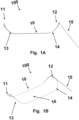
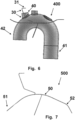
- FIG. 1A a schematic diagram of a side-view of a device 100 including a frame 10, and catheter attachment 15 in an intrinsic configuration.
- the device 100 includes a frame 10 to hold a filter and define the area, shape, and curvature of the filter.
- the back lateral portion of the frame 10 is hidden from view by the front lateral portion of the frame 10.
- the frame 10 includes intrinsic superior curves 13, 14 at both the distal end 11 and the proximal end 12.
- the proximal end 12 of the frame 11 is angled at a point of connection to a catheter.
- Catheter attachment 15 may be a stem connected to the frame and may move freely in 360 degrees.
- the catheter attachment 15 may be restricted, such as having a fixed angle at a point of connection to a catheter, such that a catheter runs substantially parallel to the central region of the frame.
- FIG. 1B a 3-dimensional schematic diagram of a device 100 in figure 1A including a frame 10, and catheter attachment 15 in an intrinsic configuration.
- the device 100 includes a frame 10 to hold a filter 16 and define the area, shape, and curvature of the filter 16.
- the back lateral portion of the frame 10 is hidden from view by the front lateral portion of the frame 10.
- the frame 10 includes intrinsic superior curves 13, 14 at both the distal end 11 and the proximal end 12.
- the proximal end 12 of the frame 11 is angled at a point of connection to a catheter.
- Catheter attachment 15 may be a stem connected to the frame and may move freely in 360 degrees.
- the shape of the filter 16 is defined by the frame 10 (i.e., the periphery of the filter 16 is attached to the frame 10, such that flexure of the frame 10 induces a change in shape (e.g., curvature) of the filter 16.
- the filter 16 of the device of Figure 1A and 1B may be inferiorly concave. This concavity allows the filter 16 to lie securely against the aorta wall upon installation in an aorta.
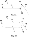
- FIG 2A a schematic diagram of a side-view of a device 200 including a frame 10, and catheter attachment 15 in an intrinsic configuration.
- the device 200 is similar to the device 100 illustrated in figures 1A and 1B except that in this intrinsic configuration, the device 200 has a proximal superior bend 14 at a proximal end 12 while the distal end 11 is flat.
- the intrinsic configuration of the device 200 has a distal superior bend 13 at a distal end 11 while the proximal end 12 is flat.
- FIG 2B a 3-dimensional schematic diagram of a device 200 in figure 1A including a frame 10, and catheter attachment 15 in an intrinsic configuration.
- the device 200 includes a frame 10 to hold a filter 16 and define the area, shape, and curvature of the filter 16.
- the shape of the filter 16 is defined by the frame 10 (i.e., the periphery of the filter 16 is attached to the frame 10, such that flexure of the frame 10 induces a change in shape (e.g., curvature) of the filter 16.
- the filter 16 of the device of Figure 2A and 2B may be inferiorly concave. This concavity allows the filter 16 to lie securely against the aorta wall upon installation in an aorta.
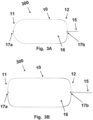
- Figures 3A and 3B are schematic diagrams illustrating a top view of a frame 10 and catheter attachment 15 having different elongated shapes.
- the device 300 may either have an intrinsic configuration as illustrated in figures 1A, 1B , 2A, 2B , but could also, in some examples, have a flat configuration.
- crimp member 17a and 17b are illustrated.
- the device 300 may have a crimp member 17a and 17b at both the distal end 11 and at the proximal end 12.
- a crimp member 17a and 17b is only arranged at either the distal end 11 or at the proximal end 12.
- a crimp member 17a, 17b is used to facilitate the crimping of the device, such as collapsible the frame 10 along a longitudinal axis of the device 300.
- the crimp members 17a, 17b are illustrated as loops made from the frame 10.
- the members could have other shapes such as triangular, or a nose or tongue shape formed by bending the frame 15 giving the nose or tongue a shape with a width narrower than the width of the frame 15.
- the crimp members 17a, 17b may either be formed to be protruding outwards, as the distal crimp 17a in figure 3A , or formed to be protruding inwards, as the distal crimp 17a in figure 3B .
- Crimp members 17a, 17b arranged to protrude inwards are it improves attachment of the filter 16 to the frame 10. Also, having the crimp members 17a, 17b arranged to protrude inwards improves the contact between the frame 10 and the walls of the aortic arch as there is nothing protruding or extending further than the frame 10.
- the catheter attachment 15 may be attached to the frame 15 via a proximal crimp member 17b, thereby allowing the catheter attachment 15 to move freely in 360 degrees.
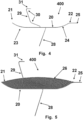
- FIG. 4 a schematic diagram of a side-view of a frame 20, stabilizers 28, 29, and catheter attachment 25 in their intrinsic configuration.
- the device 400 includes a frame 20 to hold a filter and define the area, shape, and curvature of the filter.
- the back lateral portion of the frame 20 is hidden from view by the front lateral portion of the frame 20.
- the frame 20 includes intrinsic superior curves 23, 24 at both the distal 21 end and the proximal end 22.
- the proximal end 22 of the frame 20 is angled at a point of connection 25 to a catheter, such that a catheter runs substantially parallel to the central region of the frame 10.
- the device 400 only has a superior bend, such as a superior distal bend 23 or a superior proximal bend 24.
- the frame 20 of the device 400 has crimp members as described in connection for figures 3A and 3B .
- the device 400 includes stabilizers 28, 29 that are configured to resist movement of the device upon installation in a patient's aorta.
- a front inferior stabilizer 28 is attached to the frame 20 at a central region of a front lateral portion of the frame 20.
- a back lateral stabilizer is hidden from view by the front inferior stabilizer 28, and is symmetrically attached to the frame at a central region of a back lateral portion of the frame 20.
- the inferior stabilizers 28 intrinsically point distally.
- a superior stabilizer 29 is attached to the frame 20 at a central region of opposing (e.g., back and front) lateral portions of the frame 20. The back region of the superior stabilizer 29 is hidden from view by the front region, as it is symmetrical about a coronal plane.
- the superior stabilizer 29 may be attached to the frame 20 distally from the attachment point of the inferior stabilizers 28 to the frame 20.
- the superior stabilizer 29 comprises four intrinsic proximal bends 30 (two on the front portion and two on the back portion) and a transverse curve 31 connecting the front portion to the back portion of the superior end of the superior stabilizer 29.
- FIG. 5 a schematic diagram of a side-view of the device 400 of the disclosure.
- This diagram depicts the frame 20, stabilizers 28, 29, and catheter attachment 25 as in Figure 4 , and additionally shows the filter 26.
- the shape of the filter 26 is defined by the frame (i.e., the periphery of the filter 26 is attached to the frame 20, such that flexure of the frame 20 induces a change in shape (e.g., curvature) of the filter 26.
- the filter 26 of the device of Figure 4 may be inferiorly concave. This concavity allows the filter 26 to lie securely against the aorta wall upon installation in an aorta.
- Figure 6 a schematic diagram overlying the side-view of the device 400 of Figure 4 onto an aorta, depicting the spatial relationship between the aortic space and the intrinsic configuration of the frame, stabilizers, and catheter. The same relationship would exist for a device without the stabilizers, such as a device as illustrated in Figures 1A, 1B , 2A, 2B , 3A and 3B .
- the plane of the frame is substantially transverse going from the ascending aorta 42 to the descending aorta 41.
- the superior stabilizer contacts the proximal wall 40 of the innominate artery.
- the intrinsic proximal bends 30 and the transverse curve 31 optimize contact of the superior stabilizer with the proximal wall 40 of the innominate artery.
- the inferior stabilizers shown in their intrinsic positions overlying the inferior wall of the aortic arch, are forced to bend distally upon installation of the device in the aorta and contact the proximal wall of the ascending aorta or the inferior wall of the aortic arch.
- FIG. 7 a schematic diagram showing a side-view of the installed configuration of a device 500 including the frame 50, stabilizers, and catheter attachment of Figure 4 .
- the frame 50 is inferiorly bent, such that the central portion of the frame 50 is superior to the distal 51 end and the proximal end 52 of the frame 50.
- the central attachment points of the superior and inferior stabilizers allow the stabilizers to remain in substantially the same orientation as when the frame is in its intrinsic configuration.
- Figure 8 a schematic diagram overlying the side-view of Figure 7 onto an aorta.
- the aortic walls constrain the frame, inducing the frame to bend inferiorly, such that the central portion of the frame is superior to the distal and proximal ends of the frame.
- This flexure provides outward force on the aortic walls (white arrows), enhancing the stability of the frame in a position suitable to prevent emboli from entering arteries branching from the aorta.
Landscapes
- Health & Medical Sciences (AREA)
- Cardiology (AREA)
- Oral & Maxillofacial Surgery (AREA)
- Transplantation (AREA)
- Engineering & Computer Science (AREA)
- Biomedical Technology (AREA)
- Heart & Thoracic Surgery (AREA)
- Vascular Medicine (AREA)
- Life Sciences & Earth Sciences (AREA)
- Animal Behavior & Ethology (AREA)
- General Health & Medical Sciences (AREA)
- Public Health (AREA)
- Veterinary Medicine (AREA)
- Surgical Instruments (AREA)
Claims (15)
- Intraaortale Vorrichtung, umfassend:ein Filterelement (16) und einen Rahmen (10), der aus mindestens einem Draht hergestellt ist, wobei das Filterelement (16) an dem Rahmen (10) befestigt ist und der Rahmen (10) eine Fläche und eine Form des Filterelements (16) definiert, indem er das Filterelement (16) umschließt;ein Crimp-Element (17a), das an einem distalen Bereich (11) des Rahmens (10) angeordnet und dazu konfiguriert ist, das Crimpen des Rahmens (10) entlang einer Längsachse des Rahmens (10) zu erleichtern, wobei das Crimp-Element (17a) so geformt ist, dass es nach innen vorsteht;einen Katheteraufsatz (15) mit einer länglichen Form, der an einem proximalen Bereich (12) des Rahmens (10) angeordnet ist.
- Intraaortale Vorrichtung nach Anspruch 1, wobei ein zweites Crimp-Element (17b) am proximalen Bereich (12) angeordnet ist.
- Intraaortale Vorrichtung nach Anspruch 2, wobei der Katheteraufsatz (15) über das zweite Crimp-Element (17b) am Rahmen (10) befestigt ist.
- Intraaortale Vorrichtung nach einem der Ansprüche 1 bis 3, wobei das Crimp-Element (17a) eine aus dem Rahmen (10) geformte Schlaufe ist.
- Intraaortale Vorrichtung nach einem der Ansprüche 2 bis 4, wobei das zweite Crimp-Element (17b) eine aus dem Rahmen (10) geformte Schlaufe ist.
- Intraaortale Vorrichtung nach einem der Ansprüche 2 bis 5, wobei das zweite Crimp-Element (17b) so geformt ist, dass es nach innen ragt.
- Intraaortale Vorrichtung nach einem der Ansprüche 2 bis 6, wobei das zweite Crimp-Element (17b) das Zusammenklappen des Rahmens (10) entlang einer Längsachse des Rahmens (10) erleichtert.
- Intraaortale Vorrichtung nach einem der Ansprüche 1 bis 7, wobei das Filterelement (16) so konfiguriert ist, dass es mehr als eine von der Aorta abzweigende Arterie überspannt.
- Intraaortale Vorrichtung nach einem der Ansprüche 1 bis 8, wobei die Ebene des Rahmens (10) so konfiguriert ist, dass sie im Wesentlichen quer verläuft und gleichzeitig mit einer aufsteigenden Aorta und einer absteigenden Aorta in Kontakt gehalten wird.
- Intraaortale Vorrichtung nach einem der Ansprüche 1 bis 9, wobei das Filterelement (16) eine Vielzahl gewebter Fasern umfasst, die ein Netz bilden.
- Intraaortale Vorrichtung nach einem der Ansprüche 1 bis 10, wobei der Rahmen (10) aus Nitinol besteht.
- Intraaortale Vorrichtung nach einem der Ansprüche 1 bis 11, wobei der Rahmen (10) ein Federringdraht ist.
- Intraaortale Vorrichtung nach einem der Ansprüche 1 bis 12, wobei der Katheteraufsatz (15) so angeordnet ist, dass er sich frei um 360 Grad bewegen kann.
- Intraaortale Vorrichtung nach einem der Ansprüche 1 bis 13, wobei der Katheteraufsatz (15) ein Schaft ist.
- Intraaortale Vorrichtung nach einem der Ansprüche 1 bis 14, wobei das Filterelement (16) aus einem Polymer besteht.
Priority Applications (1)
| Application Number | Priority Date | Filing Date | Title |
|---|---|---|---|
| EP25159781.1A EP4555974A3 (de) | 2016-03-10 | 2017-03-10 | Intraaortale vorrichtung |
Applications Claiming Priority (3)
| Application Number | Priority Date | Filing Date | Title |
|---|---|---|---|
| US201662306454P | 2016-03-10 | 2016-03-10 | |
| EP17710240.7A EP3426188B1 (de) | 2016-03-10 | 2017-03-10 | Intra-aortale vorrichtung |
| PCT/EP2017/055721 WO2017153587A1 (en) | 2016-03-10 | 2017-03-10 | Intra-aortic device |
Related Parent Applications (2)
| Application Number | Title | Priority Date | Filing Date |
|---|---|---|---|
| EP17710240.7A Division EP3426188B1 (de) | 2016-03-10 | 2017-03-10 | Intra-aortale vorrichtung |
| EP17710240.7A Division-Into EP3426188B1 (de) | 2016-03-10 | 2017-03-10 | Intra-aortale vorrichtung |
Related Child Applications (1)
| Application Number | Title | Priority Date | Filing Date |
|---|---|---|---|
| EP25159781.1A Division EP4555974A3 (de) | 2016-03-10 | 2017-03-10 | Intraaortale vorrichtung |
Publications (2)
| Publication Number | Publication Date |
|---|---|
| EP4049618A1 EP4049618A1 (de) | 2022-08-31 |
| EP4049618B1 true EP4049618B1 (de) | 2025-02-26 |
Family
ID=58266638
Family Applications (3)
| Application Number | Title | Priority Date | Filing Date |
|---|---|---|---|
| EP25159781.1A Pending EP4555974A3 (de) | 2016-03-10 | 2017-03-10 | Intraaortale vorrichtung |
| EP22168897.1A Active EP4049618B1 (de) | 2016-03-10 | 2017-03-10 | Intra-aortale vorrichtung |
| EP17710240.7A Active EP3426188B1 (de) | 2016-03-10 | 2017-03-10 | Intra-aortale vorrichtung |
Family Applications Before (1)
| Application Number | Title | Priority Date | Filing Date |
|---|---|---|---|
| EP25159781.1A Pending EP4555974A3 (de) | 2016-03-10 | 2017-03-10 | Intraaortale vorrichtung |
Family Applications After (1)
| Application Number | Title | Priority Date | Filing Date |
|---|---|---|---|
| EP17710240.7A Active EP3426188B1 (de) | 2016-03-10 | 2017-03-10 | Intra-aortale vorrichtung |
Country Status (3)
| Country | Link |
|---|---|
| US (2) | US20190076231A1 (de) |
| EP (3) | EP4555974A3 (de) |
| WO (1) | WO2017153587A1 (de) |
Families Citing this family (25)
| Publication number | Priority date | Publication date | Assignee | Title |
|---|---|---|---|---|
| EP4555974A3 (de) | 2016-03-10 | 2025-08-06 | Keystone Heart Ltd. | Intraaortale vorrichtung |
| CN107693161A (zh) * | 2017-10-13 | 2018-02-16 | 杭州启明医疗器械有限公司 | 血栓防护装置 |
| EP3476365B1 (de) * | 2017-10-27 | 2024-12-04 | Keystone Heart Ltd. | Kuppelförmige filtervorrichtung und verfahren zur herstellung davon |
| WO2019195860A2 (en) | 2018-04-04 | 2019-10-10 | Vdyne, Llc | Devices and methods for anchoring transcatheter heart valve |
| US10321995B1 (en) | 2018-09-20 | 2019-06-18 | Vdyne, Llc | Orthogonally delivered transcatheter heart valve replacement |
| US11344413B2 (en) | 2018-09-20 | 2022-05-31 | Vdyne, Inc. | Transcatheter deliverable prosthetic heart valves and methods of delivery |
| US11278437B2 (en) | 2018-12-08 | 2022-03-22 | Vdyne, Inc. | Compression capable annular frames for side delivery of transcatheter heart valve replacement |
| US10595994B1 (en) | 2018-09-20 | 2020-03-24 | Vdyne, Llc | Side-delivered transcatheter heart valve replacement |
| US12186187B2 (en) | 2018-09-20 | 2025-01-07 | Vdyne, Inc. | Transcatheter deliverable prosthetic heart valves and methods of delivery |
| US11071627B2 (en) | 2018-10-18 | 2021-07-27 | Vdyne, Inc. | Orthogonally delivered transcatheter heart valve frame for valve in valve prosthesis |
| US11109969B2 (en) | 2018-10-22 | 2021-09-07 | Vdyne, Inc. | Guidewire delivery of transcatheter heart valve |
| US11253359B2 (en) | 2018-12-20 | 2022-02-22 | Vdyne, Inc. | Proximal tab for side-delivered transcatheter heart valves and methods of delivery |
| WO2020146842A1 (en) | 2019-01-10 | 2020-07-16 | Vdyne, Llc | Anchor hook for side-delivery transcatheter heart valve prosthesis |
| US11185409B2 (en) | 2019-01-26 | 2021-11-30 | Vdyne, Inc. | Collapsible inner flow control component for side-delivered transcatheter heart valve prosthesis |
| US11273032B2 (en) | 2019-01-26 | 2022-03-15 | Vdyne, Inc. | Collapsible inner flow control component for side-deliverable transcatheter heart valve prosthesis |
| CN120899433A (zh) | 2019-03-05 | 2025-11-07 | 维迪内股份有限公司 | 用于正交经导管心脏瓣膜假体的三尖瓣反流控制装置 |
| US11076956B2 (en) | 2019-03-14 | 2021-08-03 | Vdyne, Inc. | Proximal, distal, and anterior anchoring tabs for side-delivered transcatheter mitral valve prosthesis |
| US11173027B2 (en) | 2019-03-14 | 2021-11-16 | Vdyne, Inc. | Side-deliverable transcatheter prosthetic valves and methods for delivering and anchoring the same |
| CN120827457A (zh) | 2019-05-04 | 2025-10-24 | 维迪内股份有限公司 | 用于在自体瓣环中部署侧面递送的假体心脏瓣膜的束紧装置和方法 |
| DE102020110715A1 (de) * | 2019-06-28 | 2020-12-31 | Protembis Gmbh | Embolieschutzvorrichtung zur Zuführung in einen Aortenbogen |
| CA3152042A1 (en) | 2019-08-20 | 2021-02-25 | Vdyne, Inc. | Delivery and retrieval devices and methods for side-deliverable transcatheter prosthetic valves |
| AU2020337235A1 (en) | 2019-08-26 | 2022-03-24 | Vdyne, Inc. | Side-deliverable transcatheter prosthetic valves and methods for delivering and anchoring the same |
| US11234813B2 (en) | 2020-01-17 | 2022-02-01 | Vdyne, Inc. | Ventricular stability elements for side-deliverable prosthetic heart valves and methods of delivery |
| CN111407461B (zh) * | 2020-03-16 | 2025-01-28 | 科凯(南通)生命科学有限公司 | 一种用于手术的血栓过滤装置 |
| CN112022427B (zh) * | 2020-11-05 | 2021-03-23 | 上海微创医疗器械(集团)有限公司 | 抗栓塞保护装置及医疗器械 |
Citations (18)
| Publication number | Priority date | Publication date | Assignee | Title |
|---|---|---|---|---|
| WO2000044308A2 (en) | 1999-02-01 | 2000-08-03 | Board Of Regents, The University Of Texas System | Woven intravascular devices and methods for making the same and apparatus for delivery of the same |
| US20010039450A1 (en) | 1999-06-02 | 2001-11-08 | Dusan Pavcnik | Implantable vascular device |
| US20070233180A1 (en) | 2001-12-21 | 2007-10-04 | Abbott Laboratories | Support frame for an embolic protection device |
| US20100179583A1 (en) | 2006-09-11 | 2010-07-15 | Carpenter Judith T | Methods of deploying and retrieving an embolic diversion device |
| US20100179585A1 (en) | 2006-09-11 | 2010-07-15 | Carpenter Judith T | Embolic deflection device |
| US20100324589A1 (en) | 2006-09-11 | 2010-12-23 | Carpenter Judith T | Embolic deflection device |
| US20110295304A1 (en) | 2008-09-04 | 2011-12-01 | Joensson Anders | Temporary Embolic Protection Device And Medical Procedure For Delivery Thereof |
| WO2012085916A2 (en) | 2010-12-23 | 2012-06-28 | Smt Research And Development Ltd. | Device and method for deflecting emboli in an aorta |
| US20120165860A1 (en) | 2006-05-08 | 2012-06-28 | S.M.T. Research & Development Ltd. | Device and method for vascular filter |
| US20140257362A1 (en) | 2013-03-07 | 2014-09-11 | St. Jude Medical, Cardiology Division, Inc. | Filtering and removing particulates from bloodstream |
| WO2014145598A1 (en) | 2013-03-15 | 2014-09-18 | Volcano Corporation | Retrieval and centering device and method with pressure and ultrasound features |
| WO2014188410A2 (en) | 2013-05-21 | 2014-11-27 | Keystone Heart Ltd. | Intravascular devices |
| WO2015177322A1 (en) | 2014-05-21 | 2015-11-26 | Swat Medical Ab | Improved embolic protection device and method |
| US20160058538A1 (en) | 2014-08-29 | 2016-03-03 | Ram H. Paul | Low profile intraluminal filters |
| US20160175085A1 (en) | 2013-03-14 | 2016-06-23 | Volcano Corporation | Enhanced fluorogenic endoluminal filter structure |
| WO2016116816A2 (en) | 2015-01-20 | 2016-07-28 | Keystone Heart Ltd. | Intravascular devices and delivery systems and uses thereof |
| WO2017153587A1 (en) | 2016-03-10 | 2017-09-14 | Keystone Heart Ltd. | Intra-aortic device |
| WO2018077458A1 (de) | 2016-10-28 | 2018-05-03 | Protembis Gmbh | Embolieschutzvorrichtung, verfahren zu deren faltung und formvorrichtung |
Family Cites Families (19)
| Publication number | Priority date | Publication date | Assignee | Title |
|---|---|---|---|---|
| US4627436A (en) | 1984-03-01 | 1986-12-09 | Innoventions Biomedical Inc. | Angioplasty catheter and method for use thereof |
| ATE490736T1 (de) | 2004-05-21 | 2010-12-15 | Micro Therapeutics Inc | Mit biologischen oder biologisch abbaubaren oder synthetischen polymeren oder fasern umschlungene metallspulen zur embolisierung einer körperhöhle |
| AU2006304660B2 (en) | 2005-10-19 | 2013-10-24 | Pulsar Vascular, Inc. | Methods and systems for endovascularly clipping and repairing lumen and tissue defects |
| US20100179647A1 (en) * | 2006-09-11 | 2010-07-15 | Carpenter Judith T | Methods of reducing embolism to cerebral circulation as a consequence of an index cardiac procedure |
| US8460335B2 (en) * | 2006-09-11 | 2013-06-11 | Embrella Cardiovascular, Inc. | Method of deflecting emboli from the cerebral circulation |
| DE102007038446A1 (de) * | 2007-08-14 | 2009-02-19 | pfm Produkte für die Medizin AG | Embolisiereinrichtung |
| US9055997B2 (en) * | 2010-12-30 | 2015-06-16 | Claret Medical, Inc. | Method of isolating the cerebral circulation during a cardiac procedure |
| US8948848B2 (en) * | 2011-01-07 | 2015-02-03 | Innovative Cardiovascular Solutions, Llc | Angiography catheter |
| EP2770951A1 (de) * | 2011-10-25 | 2014-09-03 | Boston Scientific Scimed, Inc. | Embolischer schmutzabweiser |
| EP4190387A1 (de) | 2011-11-10 | 2023-06-07 | Medtronic, Inc. | System zum einsatz einer vorrichtung an einer distalen stelle über einem erkrankten gefäss |
| WO2014061013A1 (en) | 2012-10-16 | 2014-04-24 | Keystone Heart Ltd. | Interlaced particulate filter |
| EP2732794A1 (de) * | 2012-11-14 | 2014-05-21 | Contego AB | Verbesserte Embolieschutzvorrichtung und Verfahren |
| US10973618B2 (en) * | 2013-03-01 | 2021-04-13 | St. Jude Medical, Cardiology Division, Inc. | Embolic protection device |
| US20140249566A1 (en) * | 2013-03-01 | 2014-09-04 | Aga Medical Corporation | Embolic protection shield |
| ES2911265T3 (es) | 2013-05-14 | 2022-05-18 | Transverse Medical Inc | Aparatos basados en catéteres |
| EP2859864A1 (de) * | 2013-10-14 | 2015-04-15 | Protembis GmbH | Medizinische Vorrichtung für Embolieschutz |
| EP3091937B1 (de) | 2014-01-10 | 2024-03-20 | Keystone Heart Ltd. | Unabhängiger anatomiedeflektor |
| US20160175084A1 (en) * | 2014-12-19 | 2016-06-23 | Volcano Corporation | Biodegradable filter and support frame |
| US10335261B2 (en) * | 2015-04-16 | 2019-07-02 | Sanford Health | Vessel filter and methods for use |
-
2017
- 2017-03-10 EP EP25159781.1A patent/EP4555974A3/de active Pending
- 2017-03-10 WO PCT/EP2017/055721 patent/WO2017153587A1/en not_active Ceased
- 2017-03-10 EP EP22168897.1A patent/EP4049618B1/de active Active
- 2017-03-10 US US16/083,870 patent/US20190076231A1/en not_active Abandoned
- 2017-03-10 EP EP17710240.7A patent/EP3426188B1/de active Active
-
2022
- 2022-02-25 US US17/652,665 patent/US11850137B2/en active Active
Patent Citations (21)
| Publication number | Priority date | Publication date | Assignee | Title |
|---|---|---|---|---|
| WO2000044308A2 (en) | 1999-02-01 | 2000-08-03 | Board Of Regents, The University Of Texas System | Woven intravascular devices and methods for making the same and apparatus for delivery of the same |
| US20010039450A1 (en) | 1999-06-02 | 2001-11-08 | Dusan Pavcnik | Implantable vascular device |
| US20070233180A1 (en) | 2001-12-21 | 2007-10-04 | Abbott Laboratories | Support frame for an embolic protection device |
| US20120165860A1 (en) | 2006-05-08 | 2012-06-28 | S.M.T. Research & Development Ltd. | Device and method for vascular filter |
| US20100179583A1 (en) | 2006-09-11 | 2010-07-15 | Carpenter Judith T | Methods of deploying and retrieving an embolic diversion device |
| US20100179585A1 (en) | 2006-09-11 | 2010-07-15 | Carpenter Judith T | Embolic deflection device |
| US20100324589A1 (en) | 2006-09-11 | 2010-12-23 | Carpenter Judith T | Embolic deflection device |
| US20140257366A1 (en) | 2008-09-04 | 2014-09-11 | Swat Medical Ab | Temporary Embolic Protection Device And Medical Procedure For Delivery Thereof |
| US20110295304A1 (en) | 2008-09-04 | 2011-12-01 | Joensson Anders | Temporary Embolic Protection Device And Medical Procedure For Delivery Thereof |
| US20140074152A1 (en) | 2010-12-23 | 2014-03-13 | Keystone Heart Ltd. | Device and method for deflecting emboli in an aorta |
| WO2012085916A2 (en) | 2010-12-23 | 2012-06-28 | Smt Research And Development Ltd. | Device and method for deflecting emboli in an aorta |
| US20140257362A1 (en) | 2013-03-07 | 2014-09-11 | St. Jude Medical, Cardiology Division, Inc. | Filtering and removing particulates from bloodstream |
| US20160175085A1 (en) | 2013-03-14 | 2016-06-23 | Volcano Corporation | Enhanced fluorogenic endoluminal filter structure |
| WO2014145598A1 (en) | 2013-03-15 | 2014-09-18 | Volcano Corporation | Retrieval and centering device and method with pressure and ultrasound features |
| WO2014188410A2 (en) | 2013-05-21 | 2014-11-27 | Keystone Heart Ltd. | Intravascular devices |
| WO2015177322A1 (en) | 2014-05-21 | 2015-11-26 | Swat Medical Ab | Improved embolic protection device and method |
| US20160058538A1 (en) | 2014-08-29 | 2016-03-03 | Ram H. Paul | Low profile intraluminal filters |
| WO2016116816A2 (en) | 2015-01-20 | 2016-07-28 | Keystone Heart Ltd. | Intravascular devices and delivery systems and uses thereof |
| WO2017153587A1 (en) | 2016-03-10 | 2017-09-14 | Keystone Heart Ltd. | Intra-aortic device |
| WO2018077458A1 (de) | 2016-10-28 | 2018-05-03 | Protembis Gmbh | Embolieschutzvorrichtung, verfahren zu deren faltung und formvorrichtung |
| DE102016012869A1 (de) | 2016-10-28 | 2018-05-03 | Protembis Gmbh | Embolieschutzvorrichtung, Verfahren zu deren Faltung und Formvorrichtung |
Non-Patent Citations (1)
| Title |
|---|
| ANONYMOUS: "Crimp (joining)", WIKIPEDIA, 28 October 2025 (2025-10-28), pages 1 - 10, XP093342045, Retrieved from the Internet <URL:https://en.wikipedia.org/w/index.php?title=Crimp_(joining)&oldid=1319148108> |
Also Published As
| Publication number | Publication date |
|---|---|
| US20190076231A1 (en) | 2019-03-14 |
| US11850137B2 (en) | 2023-12-26 |
| WO2017153587A1 (en) | 2017-09-14 |
| US20220183814A1 (en) | 2022-06-16 |
| EP4555974A2 (de) | 2025-05-21 |
| EP4049618A1 (de) | 2022-08-31 |
| EP3426188B1 (de) | 2022-09-21 |
| EP3426188A1 (de) | 2019-01-16 |
| EP4555974A3 (de) | 2025-08-06 |
Similar Documents
| Publication | Publication Date | Title |
|---|---|---|
| US11850137B2 (en) | Intra-aortic device | |
| JP7157131B2 (ja) | 血管内装置および送達システム | |
| US20230414336A1 (en) | Anatomy Independent Deflector | |
| US10624732B2 (en) | Endovascular device for entrapment of participate matter and method for use | |
| JP5896575B2 (ja) | 血管造影用カテーテル | |
| US10588763B2 (en) | Linked deflection devices, systems and methods for the prevention of stroke | |
| HK40029294A (en) | An intravascular device for deflecting emboli and a delivery system | |
| HK1234638B (zh) | 使血栓偏转的血管内装置、输送系统、相关方法及导管 | |
| HK40014357A (en) | Device for deflecting emboli and related system | |
| HK1234638A1 (en) | Intravascular devices and delivery systems and uses thereof |
Legal Events
| Date | Code | Title | Description |
|---|---|---|---|
| PUAI | Public reference made under article 153(3) epc to a published international application that has entered the european phase |
Free format text: ORIGINAL CODE: 0009012 |
|
| STAA | Information on the status of an ep patent application or granted ep patent |
Free format text: STATUS: THE APPLICATION HAS BEEN PUBLISHED |
|
| AC | Divisional application: reference to earlier application |
Ref document number: 3426188 Country of ref document: EP Kind code of ref document: P |
|
| AK | Designated contracting states |
Kind code of ref document: A1 Designated state(s): AL AT BE BG CH CY CZ DE DK EE ES FI FR GB GR HR HU IE IS IT LI LT LU LV MC MK MT NL NO PL PT RO RS SE SI SK SM TR |
|
| STAA | Information on the status of an ep patent application or granted ep patent |
Free format text: STATUS: REQUEST FOR EXAMINATION WAS MADE |
|
| 17P | Request for examination filed |
Effective date: 20230228 |
|
| RBV | Designated contracting states (corrected) |
Designated state(s): AL AT BE BG CH CY CZ DE DK EE ES FI FR GB GR HR HU IE IS IT LI LT LU LV MC MK MT NL NO PL PT RO RS SE SI SK SM TR |
|
| GRAP | Despatch of communication of intention to grant a patent |
Free format text: ORIGINAL CODE: EPIDOSNIGR1 |
|
| STAA | Information on the status of an ep patent application or granted ep patent |
Free format text: STATUS: GRANT OF PATENT IS INTENDED |
|
| INTG | Intention to grant announced |
Effective date: 20241025 |
|
| GRAS | Grant fee paid |
Free format text: ORIGINAL CODE: EPIDOSNIGR3 |
|
| GRAA | (expected) grant |
Free format text: ORIGINAL CODE: 0009210 |
|
| STAA | Information on the status of an ep patent application or granted ep patent |
Free format text: STATUS: THE PATENT HAS BEEN GRANTED |
|
| AC | Divisional application: reference to earlier application |
Ref document number: 3426188 Country of ref document: EP Kind code of ref document: P |
|
| AK | Designated contracting states |
Kind code of ref document: B1 Designated state(s): AL AT BE BG CH CY CZ DE DK EE ES FI FR GB GR HR HU IE IS IT LI LT LU LV MC MK MT NL NO PL PT RO RS SE SI SK SM TR |
|
| REG | Reference to a national code |
Ref country code: GB Ref legal event code: FG4D |
|
| REG | Reference to a national code |
Ref country code: CH Ref legal event code: EP |
|
| REG | Reference to a national code |
Ref country code: DE Ref legal event code: R096 Ref document number: 602017088108 Country of ref document: DE |
|
| REG | Reference to a national code |
Ref country code: IE Ref legal event code: FG4D |
|
| REG | Reference to a national code |
Ref country code: NL Ref legal event code: MP Effective date: 20250226 |
|
| PG25 | Lapsed in a contracting state [announced via postgrant information from national office to epo] |
Ref country code: RS Free format text: LAPSE BECAUSE OF FAILURE TO SUBMIT A TRANSLATION OF THE DESCRIPTION OR TO PAY THE FEE WITHIN THE PRESCRIBED TIME-LIMIT Effective date: 20250526 |
|
| PG25 | Lapsed in a contracting state [announced via postgrant information from national office to epo] |
Ref country code: FI Free format text: LAPSE BECAUSE OF FAILURE TO SUBMIT A TRANSLATION OF THE DESCRIPTION OR TO PAY THE FEE WITHIN THE PRESCRIBED TIME-LIMIT Effective date: 20250226 |
|
| PG25 | Lapsed in a contracting state [announced via postgrant information from national office to epo] |
Ref country code: PL Free format text: LAPSE BECAUSE OF FAILURE TO SUBMIT A TRANSLATION OF THE DESCRIPTION OR TO PAY THE FEE WITHIN THE PRESCRIBED TIME-LIMIT Effective date: 20250226 |
|
| PGFP | Annual fee paid to national office [announced via postgrant information from national office to epo] |
Ref country code: DE Payment date: 20250417 Year of fee payment: 9 |
|
| PG25 | Lapsed in a contracting state [announced via postgrant information from national office to epo] |
Ref country code: ES Free format text: LAPSE BECAUSE OF FAILURE TO SUBMIT A TRANSLATION OF THE DESCRIPTION OR TO PAY THE FEE WITHIN THE PRESCRIBED TIME-LIMIT Effective date: 20250226 |
|
| PGFP | Annual fee paid to national office [announced via postgrant information from national office to epo] |
Ref country code: GB Payment date: 20250423 Year of fee payment: 9 |
|
| REG | Reference to a national code |
Ref country code: LT Ref legal event code: MG9D |
|
| PG25 | Lapsed in a contracting state [announced via postgrant information from national office to epo] |
Ref country code: NO Free format text: LAPSE BECAUSE OF FAILURE TO SUBMIT A TRANSLATION OF THE DESCRIPTION OR TO PAY THE FEE WITHIN THE PRESCRIBED TIME-LIMIT Effective date: 20250526 Ref country code: IS Free format text: LAPSE BECAUSE OF FAILURE TO SUBMIT A TRANSLATION OF THE DESCRIPTION OR TO PAY THE FEE WITHIN THE PRESCRIBED TIME-LIMIT Effective date: 20250626 |
|
| PG25 | Lapsed in a contracting state [announced via postgrant information from national office to epo] |
Ref country code: NL Free format text: LAPSE BECAUSE OF FAILURE TO SUBMIT A TRANSLATION OF THE DESCRIPTION OR TO PAY THE FEE WITHIN THE PRESCRIBED TIME-LIMIT Effective date: 20250226 |
|
| PG25 | Lapsed in a contracting state [announced via postgrant information from national office to epo] |
Ref country code: HR Free format text: LAPSE BECAUSE OF FAILURE TO SUBMIT A TRANSLATION OF THE DESCRIPTION OR TO PAY THE FEE WITHIN THE PRESCRIBED TIME-LIMIT Effective date: 20250226 |
|
| PG25 | Lapsed in a contracting state [announced via postgrant information from national office to epo] |
Ref country code: PT Free format text: LAPSE BECAUSE OF FAILURE TO SUBMIT A TRANSLATION OF THE DESCRIPTION OR TO PAY THE FEE WITHIN THE PRESCRIBED TIME-LIMIT Effective date: 20250626 Ref country code: LV Free format text: LAPSE BECAUSE OF FAILURE TO SUBMIT A TRANSLATION OF THE DESCRIPTION OR TO PAY THE FEE WITHIN THE PRESCRIBED TIME-LIMIT Effective date: 20250226 |
|
| PGFP | Annual fee paid to national office [announced via postgrant information from national office to epo] |
Ref country code: FR Payment date: 20250407 Year of fee payment: 9 |
|
| PG25 | Lapsed in a contracting state [announced via postgrant information from national office to epo] |
Ref country code: BG Free format text: LAPSE BECAUSE OF FAILURE TO SUBMIT A TRANSLATION OF THE DESCRIPTION OR TO PAY THE FEE WITHIN THE PRESCRIBED TIME-LIMIT Effective date: 20250226 Ref country code: GR Free format text: LAPSE BECAUSE OF FAILURE TO SUBMIT A TRANSLATION OF THE DESCRIPTION OR TO PAY THE FEE WITHIN THE PRESCRIBED TIME-LIMIT Effective date: 20250527 |
|
| REG | Reference to a national code |
Ref country code: AT Ref legal event code: MK05 Ref document number: 1769914 Country of ref document: AT Kind code of ref document: T Effective date: 20250226 |
|
| PG25 | Lapsed in a contracting state [announced via postgrant information from national office to epo] |
Ref country code: SE Free format text: LAPSE BECAUSE OF FAILURE TO SUBMIT A TRANSLATION OF THE DESCRIPTION OR TO PAY THE FEE WITHIN THE PRESCRIBED TIME-LIMIT Effective date: 20250226 |
|
| PG25 | Lapsed in a contracting state [announced via postgrant information from national office to epo] |
Ref country code: SM Free format text: LAPSE BECAUSE OF FAILURE TO SUBMIT A TRANSLATION OF THE DESCRIPTION OR TO PAY THE FEE WITHIN THE PRESCRIBED TIME-LIMIT Effective date: 20250226 |
|
| PG25 | Lapsed in a contracting state [announced via postgrant information from national office to epo] |
Ref country code: DK Free format text: LAPSE BECAUSE OF FAILURE TO SUBMIT A TRANSLATION OF THE DESCRIPTION OR TO PAY THE FEE WITHIN THE PRESCRIBED TIME-LIMIT Effective date: 20250226 |
|
| PG25 | Lapsed in a contracting state [announced via postgrant information from national office to epo] |
Ref country code: IT Free format text: LAPSE BECAUSE OF FAILURE TO SUBMIT A TRANSLATION OF THE DESCRIPTION OR TO PAY THE FEE WITHIN THE PRESCRIBED TIME-LIMIT Effective date: 20250226 |
|
| PG25 | Lapsed in a contracting state [announced via postgrant information from national office to epo] |
Ref country code: AT Free format text: LAPSE BECAUSE OF FAILURE TO SUBMIT A TRANSLATION OF THE DESCRIPTION OR TO PAY THE FEE WITHIN THE PRESCRIBED TIME-LIMIT Effective date: 20250226 |
|
| PG25 | Lapsed in a contracting state [announced via postgrant information from national office to epo] |
Ref country code: EE Free format text: LAPSE BECAUSE OF FAILURE TO SUBMIT A TRANSLATION OF THE DESCRIPTION OR TO PAY THE FEE WITHIN THE PRESCRIBED TIME-LIMIT Effective date: 20250226 Ref country code: CZ Free format text: LAPSE BECAUSE OF FAILURE TO SUBMIT A TRANSLATION OF THE DESCRIPTION OR TO PAY THE FEE WITHIN THE PRESCRIBED TIME-LIMIT Effective date: 20250226 |
|
| PG25 | Lapsed in a contracting state [announced via postgrant information from national office to epo] |
Ref country code: RO Free format text: LAPSE BECAUSE OF FAILURE TO SUBMIT A TRANSLATION OF THE DESCRIPTION OR TO PAY THE FEE WITHIN THE PRESCRIBED TIME-LIMIT Effective date: 20250226 |
|
| REG | Reference to a national code |
Ref country code: CH Ref legal event code: H13 Free format text: ST27 STATUS EVENT CODE: U-0-0-H10-H13 (AS PROVIDED BY THE NATIONAL OFFICE) Effective date: 20251024 |
|
| PG25 | Lapsed in a contracting state [announced via postgrant information from national office to epo] |
Ref country code: SK Free format text: LAPSE BECAUSE OF FAILURE TO SUBMIT A TRANSLATION OF THE DESCRIPTION OR TO PAY THE FEE WITHIN THE PRESCRIBED TIME-LIMIT Effective date: 20250226 |
|
| PG25 | Lapsed in a contracting state [announced via postgrant information from national office to epo] |
Ref country code: LU Free format text: LAPSE BECAUSE OF NON-PAYMENT OF DUE FEES Effective date: 20250310 |
|
| REG | Reference to a national code |
Ref country code: DE Ref legal event code: R026 Ref document number: 602017088108 Country of ref document: DE |
|
| PLBI | Opposition filed |
Free format text: ORIGINAL CODE: 0009260 |
|
| PLAX | Notice of opposition and request to file observation + time limit sent |
Free format text: ORIGINAL CODE: EPIDOSNOBS2 |