EP4049079B1 - Optisches system für ein lichtblattmikroskop - Google Patents
Optisches system für ein lichtblattmikroskop Download PDFInfo
- Publication number
- EP4049079B1 EP4049079B1 EP20807289.2A EP20807289A EP4049079B1 EP 4049079 B1 EP4049079 B1 EP 4049079B1 EP 20807289 A EP20807289 A EP 20807289A EP 4049079 B1 EP4049079 B1 EP 4049079B1
- Authority
- EP
- European Patent Office
- Prior art keywords
- light
- image
- sample
- light sheet
- transport optics
- Prior art date
- Legal status (The legal status is an assumption and is not a legal conclusion. Google has not performed a legal analysis and makes no representation as to the accuracy of the status listed.)
- Active
Links
Images



Classifications
-
- G—PHYSICS
- G02—OPTICS
- G02B—OPTICAL ELEMENTS, SYSTEMS OR APPARATUS
- G02B21/00—Microscopes
- G02B21/0004—Microscopes specially adapted for specific applications
- G02B21/002—Scanning microscopes
- G02B21/0024—Confocal scanning microscopes (CSOMs) or confocal "macroscopes"; Accessories which are not restricted to use with CSOMs, e.g. sample holders
- G02B21/0032—Optical details of illumination, e.g. light-sources, pinholes, beam splitters, slits, fibers
-
- G—PHYSICS
- G02—OPTICS
- G02B—OPTICAL ELEMENTS, SYSTEMS OR APPARATUS
- G02B21/00—Microscopes
- G02B21/0004—Microscopes specially adapted for specific applications
- G02B21/002—Scanning microscopes
- G02B21/0024—Confocal scanning microscopes (CSOMs) or confocal "macroscopes"; Accessories which are not restricted to use with CSOMs, e.g. sample holders
- G02B21/0036—Scanning details, e.g. scanning stages
-
- G—PHYSICS
- G02—OPTICS
- G02B—OPTICAL ELEMENTS, SYSTEMS OR APPARATUS
- G02B21/00—Microscopes
- G02B21/0004—Microscopes specially adapted for specific applications
- G02B21/002—Scanning microscopes
- G02B21/0024—Confocal scanning microscopes (CSOMs) or confocal "macroscopes"; Accessories which are not restricted to use with CSOMs, e.g. sample holders
- G02B21/0052—Optical details of the image generation
- G02B21/006—Optical details of the image generation focusing arrangements; selection of the plane to be imaged
-
- G—PHYSICS
- G02—OPTICS
- G02B—OPTICAL ELEMENTS, SYSTEMS OR APPARATUS
- G02B21/00—Microscopes
- G02B21/06—Means for illuminating specimens
- G02B21/08—Condensers
- G02B21/10—Condensers affording dark-field illumination
-
- G—PHYSICS
- G02—OPTICS
- G02B—OPTICAL ELEMENTS, SYSTEMS OR APPARATUS
- G02B21/00—Microscopes
- G02B21/16—Microscopes adapted for ultraviolet illumination ; Fluorescence microscopes
-
- G—PHYSICS
- G02—OPTICS
- G02B—OPTICAL ELEMENTS, SYSTEMS OR APPARATUS
- G02B21/00—Microscopes
- G02B21/36—Microscopes arranged for photographic purposes or projection purposes or digital imaging or video purposes including associated control and data processing arrangements
- G02B21/365—Control or image processing arrangements for digital or video microscopes
- G02B21/367—Control or image processing arrangements for digital or video microscopes providing an output produced by processing a plurality of individual source images, e.g. image tiling, montage, composite images, depth sectioning, image comparison
Definitions
- the invention relates to an optical system for a light sheet microscope, with a transport optics which is designed to image a light sheet for illuminating a sample plane lying obliquely to the optical axis of the transport optics in a sample and to image the illuminated sample plane in the intermediate image space.
- the invention further relates to a method for illuminating a sample in a light sheet microscope.
- the detection plane is slanted in the sample. This means that only a limited angular range and thus only a partial range of the spatial frequencies of the sample is detected, in contrast to the coverage of the frequency space when detecting a plane perpendicular to the optical axis. Furthermore, the illumination light sheet propagates through part of the sample to the sample area, which leads to the scattering and shadowing artifacts known from light sheet microscopy.
- Optical systems for light sheet microscopes according to the preamble of claim 1 are known from the publications DE 102016103182 A2 , DE102018204940 A1 and DE102014102215 A1 known.
- Microscope systems which each have an alternating system with two light deflection elements in an observation beam path, of which a first light deflection element causes an image inversion in only one direction and a second light deflection element causes a complete image inversion in two directions.
- a key advantage of inclined plane microscopy is its compatibility with conventional sample formats.
- Multi-sided structures known as “multiview light sheets” require optical access to the sample from the opposite direction.
- sample formats such as Petri dishes. or multititer plates.
- Even structures such as Wu et al., Nature Biotechnology, Volume 31, pages 1032-1038 (2013 ) are not suitable for testing in multititer plates and require duplication of the beam paths, which is costly.
- the optical system for a light sheet microscope has a transport optics which is designed to image a light sheet for illuminating a sample plane lying obliquely to the optical axis of the transport optics into a sample and to image the illuminated sample plane into an intermediate image space.
- the transport optics comprises a changeover system which has at least a first and a second light deflection element.
- the transport optics is further designed to switch an illumination direction along which the light sheet illuminates the sample by the first and the second light deflection element being alternately introduced into a beam path of the transport optics.
- the first light deflection element causes a partial image reversal. in only one direction and the second light deflection element causes a complete image reversal in two directions.
- the transport optics project the light sheet into the sample.
- the light sheet runs parallel to the optical axis of the transport optics. This directs the light sheet into a part of the entrance pupil of an objective facing the sample, which is offset laterally from the center of the entrance pupil.
- the entrance pupil of the objective is thus illuminated decentrally, which means that the light sheet is directed into the sample at an angle to the optical axis.
- this type of light sheet microscope is also called an inclined plane microscope.
- the introduction of the first light deflection element causes a first image reversal, for example a swapping of top and bottom in the beam path of the transport optics in front of the lens.
- the introduction of the second light deflection element now causes an additional swapping of left and right in the beam path of the transport optics in front of the lens. If the second light deflection element is introduced into the beam path of the transport optics, the light sheet is directed into a different part of the entrance pupil of the lens facing the sample. This in turn leads to the light sheet being directed into the sample from a different direction at an angle to the optical axis.
- the introduction of the second light deflection element therefore switches the direction of illumination.
- the objective is located below the sample table.
- the imaging beam path is usually deflected to the side by a deflection element (e.g. a mirror).
- an image erection unit is located in the detection beam path, which is realized by two opposing and tilted lenses.
- the bending axis is usually given by the gravitational axis.
- the bending axis is therefore parallel to the optical axis of the sample-side objective in an inverted microscope system. This means that the horizontal optical beam path between the deflection and the image erection unit maintains mirror symmetry with respect to top/bottom, but not with respect to right/left.
- the asymmetrical direction of both the image field and the pupil is exchanged by modifying the above-mentioned deflection element, which turns the vertical beam path into a horizontal beam path.
- This can be achieved by replacing a simple deflection element with a reflective surface with a deflection element with a roof edge using a changeover mechanism. Since these are also two individual elements, they can be adjusted independently of one another, in contrast to an image field rotation system, and the pupil and field image can thus be centered.
- the optical path lengths are also equal.
- such a pair of deflection elements could consist of a deflection prism with a rear-face mirror (or total reflection) and an Amici roof prism, or of a simple front-face mirror and a roof mirror, which can be made from two individual elements to create an inner roof edge.
- the prisms can also be tilted so that the entrance and exit surfaces are not perpendicular to the optical axis in order to avoid reflections.
- the light sheet is generated in the inter-image space.
- the light sheet can also be coupled into the transport optics, for example by means of a beam splitter element.
- the optical system comprises a detection optics whose optical axis is tilted relative to the optical axis of the transport optics about a tilt axis that runs through the intermediate image space.
- the detection optics images the sample planes imaged by the transport optics into the intermediate image space, for example onto an image sensor.
- the detection optics are preferably arranged such that the sample planes imaged into the intermediate image space are perpendicular to the optical axis of the detection optics.
- the optical system comprises a scanning device for step-by-step illumination of several sample planes that follow one another along a scanning direction with the light sheet.
- the detection optics are further designed to generate a layer image from an image of the respective sample plane generated in the intermediate image space.
- a layer image stack can be assembled from the layer images, which can be further processed into a volume image, ie a three-dimensional image of the sample. This allows high-resolution volume images of areas of the sample to be generated.
- the scanning device comprises at least one raster mirror, by means of which the light sheet can be moved transversely to the optical axis of the transport optics.
- the raster mirror is preferably arranged in an infinite beam path of the transport optics, i.e. at a location along the beam path of the transport optics where the beams are largely parallel. This is a mechanically simple design of the scanning device.
- the scanning device comprises at least one focusing device for setting a focal plane of the transport optics.
- This focusing device can in particular be an objective of the transport optics facing the intermediate image space. Since, unlike when using a raster mirror, no infinite beam path is required within the beam path of the transport optics, this alternative embodiment requires fewer optical elements in the beam path of the transport optics. Accordingly, this embodiment can be made more compact.
- the optical system comprises an image processing and control unit which is designed to introduce the first light deflection element into the beam path of the transport optics, to generate a first image data set which represents a layer image stack composed of the layer images, to introduce the second light deflection element into the beam path of the transport optics, to generate a second image data set which represents a further layer image stack composed of the layer images, and to process the first image data set and the second image data set to form a volume image of the sample.
- Volume images of the sample are now recorded with both deflection elements, i.e. with the detection plane tilted by + ⁇ and - ⁇ relative to the optical axis, with the azimuth unchanged. Both volume images are then transformed into a common geometry, e.g.
- the transport optics has a single objective facing the sample, the optical axis of which is parallel to the tilt axis.
- the single objective serves simultaneously to illuminate the sample using the light sheet and to detect the illuminated sample planes.
- the embodiment with only a single objective facing the sample has the advantage over alternative designs with separate objectives for illumination and detection that the optical axes of the objective can be aligned perpendicular to a sample carrier. This reduces reflections on the surface of the sample carrier in particular and increases the image quality of the optical system.
- the first light deflection element and the second light deflection element each deflect the beam path of the transport optics by 90°.
- the optical system is particularly suitable for light sheet microscopes that are designed as inverted microscopes.
- the optical axis of the objective facing the sample is aligned parallel to the direction of gravity.
- the optical axes of the transport optics and the detection optics, which intersect in the intermediate image space lie in a plane that is perpendicular to the direction of gravity. This arrangement is particularly stable and easy to arrange.
- the first light deflection element is a deflection mirror or a deflection prism.
- the second light deflection element is preferably a roof prism, a roof mirror or an Amici prism.
- prisms as optical elements allows for easy adjustment of the optical system. Mirror arrangements are more cost-effective.
- the second light deflection element causes an image rotation of 90°, 180° or 270°.
- additional light deflection elements can also be provided, each of which realizes different image rotations. This makes it possible to switch between more than two illumination directions and detection directions using the changeover system.
- the optical system comprises an illumination unit for generating the light sheet.
- the illumination unit is preferably arranged such that the optical axis of the illumination unit is perpendicular to the optical axis of the detection optics.
- the optical axes of the transport optics, the illumination unit and the detection optics intersect in the intermediate image space.
- the invention also relates to a light sheet microscope with an optical system of the type described above.
- the light sheet microscope is designed in particular as an inverted microscope.
- the invention further relates to a method for illuminating a sample in a light sheet microscope.
- a light sheet for illuminating a sample plane lying obliquely to the optical axis of the transport optics is imaged into a sample by means of a transport optics and the illuminated sample plane is imaged into an intermediate image space.
- An illumination direction along which the light sheet illuminates the sample is switched by alternately introducing a first and a second light deflection element into a beam path of the transport optics.
- the first light deflection element causes a partial image reversal in only one direction
- the second light deflection element causes a complete image reversal in two directions.
- Figure 1 shows a schematic representation of a light sheet microscope 100 with a scanning device 102 according to an embodiment.
- the light sheet microscope 100 comprises the scanning device 102, an illumination unit 104, a transport optics 106, a detection optics 108 and a processor 110.
- the aforementioned elements together form an embodiment of an optical system according to the invention.
- the optical axis O1 of the detection optics 108 is tilted relative to the optical axis O2 of the transport optics 106 by a tilt angle ⁇ .
- the axis V of this tilting is parallel to the direction of gravity, ie perpendicular to the plane of the Figure 1
- the optical axis O3 of the illumination unit 104 is also tilted relative to the optical axis O2 of the transport optics 106 about the tilt axis V.
- the optical axis O3 of the illumination unit 104 is perpendicular to the optical axis O1 of the detection optics 108, so that the optical axis O3 of the illumination unit 104 is tilted relative to the optical axis O2 of the transport optics 106 by an angle of 90° - ⁇ .
- the three aforementioned optical axes O1, O2, O3 intersect in an intermediate image space 112.
- the lighting unit 104 comprises a light source 114 and an illumination lens 116.
- the light source 114 generates a light sheet, for example with the aid of a Figure 1 not explicitly shown cylindrical lens, whereby the light sheet is arranged with reference to one in Figure 1 illustrated oblique-angled coordinate system extends in an illumination direction A and a direction of extension B perpendicular thereto.
- the direction of extension B is parallel to the tilt axis V, ie the direction of extension B points in the illustration according to Figure 1 from the plane of the drawing.
- the light source 114 can also generate a quasi-static light sheet by means of a scanning element provided specifically for this purpose.
- the illumination lens 116 images the light sheet into the intermediate image space 112.
- the light sheet can also be coupled directly into the transport optics 106. Such an alternative embodiment is described below with reference to Figure 2 described.
- the transport optics 106 comprises, as seen from the intermediate image space 112, a projection lens 118 facing the intermediate image space 112, a first tube lens 120, a first eyepiece 122, a second eyepiece 124, a second tube lens 126, which in the embodiment shown is designed as a lens system containing several lenses, and a further lens 128, which faces a sample 130.
- the scanning device 102 is arranged between the first eyepiece 122 and the second eyepiece 124, which in the embodiment shown is formed by a raster mirror, on which the optical axis O2 of the transport optics 106 is deflected. With the help of the movable raster mirror, the light sheet can be moved along a scanning direction C, which is perpendicular to the optical axis O2 of the transport optics 106.
- Figure 1 the objective 128 facing the sample is shown as if it were positioned like the other components of the transport optics 106 in the plane of the Figure 1 In fact, however, it is aligned perpendicular to the plane of the drawing, as can be seen from the Figures 4 and 5 results.
- an interchangeable system 132 is arranged and designed to optionally contain a first light deflection element 404 and a second light deflection element 500 (cf. Figures 4 and 5 ) into the beam path of the transport optics 106. Both the first light deflection element 404 and the second light deflection element 500 cause a deflection of the optical axis O2 of the transport optics 106 by 90° from the plane of the drawing of Figure 1 out what is in the Figures 4 and 5 is shown.
- This deflection causes an axial mirroring of the virtual image at this point of the transport optics 106 along an axis that is perpendicular to the optical axis O2 of the transport optics 106 and perpendicular to the direction of gravity.
- This axial mirroring causes a swap of top and bottom in the virtual image and is also referred to below as the first image reversal.
- the second light deflection element 500 additionally causes a second axial mirroring along an axis that is perpendicular to the optical axis O2 of the transport optics 106 and parallel to the direction of gravity.
- the second axial mirroring causes a swap of left and right in the virtual image and is also referred to below as the second image reversal.
- the transport optics 106 images the light sheet from the intermediate image space 112 into the sample 130.
- the illumination light which generates the light sheet runs with a parallel offset to the optical axis O2 of the transport optics 106.
- the light sheet is focused into a partial area of an entrance pupil 406 (see Figures 4 and 5 ) of the objective 128, which is laterally offset from the optical axis O2 of the transport optics 106 and thus from the center of the entrance pupil 406 (in Figure 1 left of the optical axis of the transport optics 106).
- the entrance pupil 406 of the objective 128 is thus decentrally illuminated, which leads to the light sheet being directed into the sample 130 at an angle to the optical axis O2 of the objective 128.
- the introduction of the second light deflection element 500 causes a swap of left and right in the beam path of the transport optics 106 in front of the lens 128. If the second light deflection element 500 is introduced into the beam path of the transport optics 106, the light sheet is guided into another part of the entrance pupil 406 of the lens 128, which is in Figure 1 to the right of the optical axis O2 of the transport optics 106. This in turn leads to the light sheet being directed into the sample 130 from a different direction at an angle to the optical axis of the objective 128.
- the detection optics 108 comprises, as seen from the intermediate image space 112, a detection objective 134, a tube lens 136 and an image sensor 138. Detection light emanating from the sample 130, which is transported by the transport optics 106 into the intermediate image space 112, is guided through the detection objective 134 and the tube lens 136 to the image sensor 138.
- the processor 110 is connected to the change system 132, the light source 114, the scanning device 102 and the image sensor 138.
- the processor 110 is designed to control the elements coupled to it and to process image data generated by the image sensor 138 in order to generate a volume image of the sample 130. This image generation is carried out using Figure 8 described in more detail later.
- the processor 110 thus forms an image processing and control unit of the light sheet microscope 100.
- Figure 2 shows a schematic representation of a light sheet microscope 200 according to another embodiment.
- the light sheet microscope 200 according to Figure 2 differs from the light sheet microscope 100 according to Figure 1 in the arrangement of the lighting unit 202 and thus in the manner in which the light sheet is coupled into the transport optics 204.
- Identical and equivalent elements are designated with the same reference numerals in Figures 1 and 2.
- the transport optics 204 of the light sheet microscope 200 comprises a beam splitter element 206, which in the embodiment shown is designed as a dichroic beam splitter.
- the beam splitter element 206 is arranged between the first eyepiece 122 and the scanning mirror of the scanning device 102 in the beam path of the transport optics 204.
- the illumination unit 202 is in Figure 2 arranged below the beam splitter element 206 and for the sake of simplicity as the only Block.
- the light sheet generated by the illumination unit 202 is coupled into the beam path of the transport optics 204 by the beam splitter element 206.
- the light sheet in the light sheet microscope 200 is Figure 2 thus not generated in the inter-image space 112.
- Figure 3 shows a schematic representation of a light sheet microscope 300 according to another embodiment.
- the light sheet microscope 300 according to Figure 3 differs from those in the Figures 1 and 2
- the light sheet microscopes 100, 200 shown essentially differ in that the scanning by the light sheet is carried out axially, ie along the optical axis O2 of the transport optics 302.
- the same and equivalent elements are shown in the Figures 1 to 3 designated by the same reference numerals.
- the transport optics 302 comprises, as seen from the intermediate image space 112, a projection lens 304, the two tube lenses 120, 126 and the lens 128 facing the sample 130.
- the projection lens 304 has an electronic focusing device 306 which is designed to focus the light sheet on different levels in the sample 130.
- the electronic focusing device 306 is connected to the processor 308.
- the scanning device is formed by the electronic focusing device 306.
- the electronic focusing device 304 enables the light sheet and simultaneously the coplanar detection plane to be moved along the optical axis O2 of the transport optics 302.
- the Figures 4 and 5 each show a schematic representation of a part of the optical system of the light sheet microscopes 100, 200 according to the Figures 1 and 2
- the illumination unit 104, 202 and the beam splitter element 206 are shown in the Figures 4 and 5 omitted in each case.
- Light bundles 400, 402 of off-axis and near-axis rays are shown by different hatching.
- the light bundle 400 of off-axis rays corresponds to the light sheet, which indeed, it is generated with a parallel offset to the optical axis O2 of the transport optics 106, 204.
- FIG 4 an operating state is shown in which the first light deflection element 404 is introduced into the beam path of the transport optics 106, 204 by the change system 132.
- the first light deflection element 404 is designed as a prism, for example.
- the first light deflection element 404 causes the first image reversal, ie the deflection of the optical axis O2 of the transport optics 106, 204 by 90° in the direction of the entrance pupil 406 of the objective 128.
- the parallel offset of the light sheet with respect to the optical axis O2 of the transport optics 106, 204 results in the light sheet entering the entrance pupil 406 laterally offset from the center of the entrance pupil 406 of the objective 128.
- the light sheet enters the entrance pupil 406 of the objective 128 to the left of the center as seen from the transport optics 106, 204.
- FIG 5 an operating state is shown in which the second light deflection element 500 is introduced into the beam path of the transport optics 106 by the change system 132.
- the second light deflection element 500 is designed as an Amici roof prism.
- the second light deflection element 500 causes both the first image reversal and the second image reversal, ie the swapping of left and right in the virtual image.
- This swapping leads to the light sheet in the operating state according to Figure 5 enters a different part of the entrance pupil 406 of the lens 128 than in the operating state according to Figure 4 , in which the first light deflection element 404 is introduced into the beam path of the transport optics 106, 204.
- the light sheet enters the entrance pupil 406 of the objective 128 to the right of the center as seen from the transport optics 106, 204.
- the Figures 4 and 5 It can be seen how the change system 132 can be used to control which part of the entrance pupil 406 of the objective 128 enters the light sheet.
- the objective 128 causes a deflection of the light sheet in the direction of the optical axis of the objective 128. Consequently, by means of the changing system 132, by selectively introducing one of the two light deflection elements 404, 500, it can be determined from which direction the sample 130 is illuminated with the light sheet.
- the Figures 6 and 7 each show a schematic representation of a part of the optical system of the light sheet microscope 300 according to Figure 3
- the lighting unit 104 is shown in the Figures 6 and 7 omitted in each case.
- Light bundles of off-axis and near-axis rays 400, 402 are shown by different hatching.
- the light bundle 400 of off-axis rays corresponds to the light sheet.
- the optical system shown does not have a grid mirror. This means that the two eyepieces 122, 124 are not required.
- Figure 8 shows the flow chart of an exemplary method for generating a volume image of the sample 130 using the light sheet microscope according to one of the Figures 1 to 3 .
- a first volume image is generated.
- the detection optics 108 generate a layer image by projecting an image of the illuminated sample plane generated in the intermediate image space 112 onto the image sensor 138.
- the individual layer images are combined to form a layer image stack, which is then further processed to form the volume image.
- step S12 the light deflection element 404, 500, which is currently located in the beam path of the transport optics 106, 204, 302, is then exchanged for the other light deflection element 500 or 404 by means of the exchange system 132.
- the illumination direction and the detection direction of the light sheet microscope 100, 200, 300 are switched.
- step S14 the steps performed in step S10 for generating the first volume image are repeated to generate a second volume image.
- the second volume image differs from the first volume image in the illumination direction from which the sample planes are illuminated with the light sheet and the detection direction in which these sample planes are imaged onto the image sensor 138.
- step S16 the two volume images are combined to form a single high-resolution volume image.
- the light deflection element 500, 404 located in the beam path of the transport optics 106, 204, 302 is exchanged for the other light deflection element 404 or 500 by means of the exchange system 132, and steps S10 to S14 are repeated. This allows a time series of volume images to be generated.
- aspects have been described in the context of a device, it is clear that these aspects also represent a description of the corresponding method, where a block or device corresponds to a method step or a function of a method step. Analogously, aspects described in the context of a method step also represent a description of a corresponding block or element or a property of a corresponding device.
Landscapes
- Physics & Mathematics (AREA)
- Chemical & Material Sciences (AREA)
- Analytical Chemistry (AREA)
- General Physics & Mathematics (AREA)
- Optics & Photonics (AREA)
- Engineering & Computer Science (AREA)
- Multimedia (AREA)
- Computer Vision & Pattern Recognition (AREA)
- Microscoopes, Condenser (AREA)
Description
- Die Erfindung betrifft ein optisches System für ein Lichtblattmikroskop, mit einer Transportoptik, die ausgebildet ist, ein Lichtblatt zum Beleuchten einer schräg zur optischen Achse der Transportoptik liegenden Probenebene in eine Probe abzubilden und die beleuchtete Probenebene in den Zwischenbildraum abzubilden. Die Erfindung betrifft ferner ein Verfahren zum Beleuchten einer Probe in einem Lichtblattmikroskop.
- In der Schiefebenenmikroskopie nach Dunsby (
US 8 582 203 B2 ) liegt die Detektionsebene schief in der Probe. Dies führt dazu, dass nur ein beschränkter Winkelbereich und damit nur ein Teilbereich der Raumfrequenzen der Probe detektiert wird, im Gegensatz zur Abdeckung des Frequenzraumes bei der Detektion einer Ebene senkrecht zur optischen Achse. Weiterhin propagiert das Beleuchtungslichtblatt bis zum Probenbereich durch einen Teil der Probe, was zu den aus der Lichtblattmikroskopie bekannten Streu- und Abschattungsartefakten führt. - Optische Systeme für Lichtblattmikroskope nach dem Oberbegriff das Anspruchs 1 sind aus den Druckschriften
DE 102016103182 A2 ,DE102018204940 A1 undDE102014102215 A1 bekannt. - Aus den Druckschriften
DE3615842A1 undUS2005/128573A1 sind Mikroskopsysteme bekannt, die jeweils in einem Beobachtungsstrahlengang ein Wechselsystem mit zwei Lichtumlenkelementen aufweisen, von denen ein erstes Lichtumlenkelement eine Bildumkehr in nur einer Richtung und ein zweites Lichtumlenkelement eine vollständige Bildumkehr in zwei Richtungen bewirkt. - In der konventionellen Lichtblattmikroskopie sind Drehvorrichtungen bekannt, oder aber auch Aufbauten, die eine Detektion aus mehreren Richtungen zulassen, wie z. B. aus U. Krzic et al., Nature Methods, Volume 9, Seiten 730 - 733 (2012) bekannt ist. In der Schiefebenenmikroskopie sind in
US 8 582 203 B2 undDE 10 2016 103 182 B4 Aufbauten mit Bildfeldrotationssystemen wie Abbe-König-Rotatoren beschrieben. - Ein entscheidender Vorteil der Schiefebenemikroskopie ist die Kompatibilität mit konventionellen Probenformaten. Durch mehrseitige Aufbauen, die als "Multiview Lightsheet" bekannt sind, ist eine optische Zugänglichkeit der Probe auch aus der Gegenrichtung notwendig. Dies ist jedoch mit konventionellen Probeformaten wie Petrischalen oder Multititerplatten inkompatibel. Auch Aufbauten, wie aus Wu et al., Nature Biotechnology, Volume 31, Seiten 1032-1038 (2013) bekannt sind, eignen sich nicht für die Untersuchung in Multititerplatten und benötigen eine Doppelung der Strahlengänge, was kostenintensiv ist.
- Die Verwendung von Bildfeldrotationssystemen ist aus praktischen Gründen ungünstig: Durch die endlichen Toleranzen der Lager sowie der Prismenflächen ist es in der Praxis nur schwer möglich, die engen Toleranzen der Zentrierung der Pupillenabbildung zu gewährleisten, die aufgrund des "Remote Focusing", auf dem die Schiefebenenmikroskopie beruht, einzuhalten sind.
- Es ist die Aufgabe der Erfindung, ein optisches System und ein Verfahren anzugeben, die ein einfaches Umschalten der Beleuchtungsrichtung und der Detektionsrichtung in einem Lichtblattmikroskop erlauben.
- Diese Aufgabe wird durch das optische System mit den Merkmalen des Anspruchs 1 und das Verfahren mit den Merkmalen des Anspruchs 14 gelöst. Vorteilhafte Weiterbildungen sind jeweils in den abhängigen Ansprüchen angegeben.
- Das optische System für ein Lichtblattmikroskop nach Anspruch 1 hat eine Transportoptik, die ausgebildet ist, ein Lichtblatt zum Beleuchten einer schräg zur optischen Achse der Transportoptik liegenden Probenebenen in eine Probe abzubilden und die beleuchtete Probenebene in einen Zwischenbildraum abzubilden. Die Transportoptik umfasst ein Wechselsystem, das mindestens ein erstes und ein zweites Lichtumlenkelement hat. Die Transportoptik ist ferner ausgebildet, eine Beleuchtungsrichtung, längs der das Lichtblatt die Probe beleuchtet, umzuschalten, indem das erste und das zweite Lichtumlenkelement abwechselnd in einen Strahlengang der Transportoptik eingebracht werden. Das erste Lichtumlenkelement bewirkt eine teilweise Bildumkehr in nur einer Richtung und das zweite Lichtumlenkelement bewirkt eine vollständige Bildumkehr in zwei Richtungen.
- Die Transportoptik bildet das Lichtblatt in die Probe ab. Das Lichtblatt verläuft dabei mit einem Parallelversatz zur optischen Achse der Transportoptik. Hierdurch wird das Lichtblatt in einen Teilbereich einer Eintrittspupille eines der Probe zugewandten Objektivs geleitet, der gegenüber der Mitte der Eintrittspupille seitlich versetzt ist. Die Eintrittspupille des Objektivs wird somit dezentral unterleuchtet, was dazu führt, dass das Lichtblatt schräg zur optischen Achse in die Probe gelenkt wird. Aus diesem Grund wird ein derartiges Lichtblattmikroskop auch als Schiefebenenmikroskop bezeichnet.
- Das Einbringen des ersten Lichtumlenkelementes bewirkt eine erste Bildumkehr, beispielsweise ein Vertauschen von oben und unten in dem Strahlengang der Transportoptik vor dem Objektiv. Das Einbringen des zweiten Lichtumlenkelementes bewirkt nun gleichsam ein zusätzliches Vertauschen von links und rechts in dem Strahlengang der Transportoptik vor dem Objektiv. Wird also das zweite Lichtumlenkelement in den Strahlengang der Transportoptik eingebracht, so wird das Lichtblatt in einen anderen Teilbereich der Eintrittspupille des der Probe zugewandten Objektivs geleitet. Dies führt wiederum dazu, dass das Lichtblatt aus einer anderen Richtung schräg zur optischen Achse in die Probe gelenkt wird. Durch das Einbringen des zweiten Lichtumlenkelementes wird folglich ein Umschalten der Beleuchtungsrichtung erreicht.
- In inversen Mikroskopieanordnungen, die auch als Schiefebenenmikroskop ausgeführt sein können, befindet sich das Objektiv unterhalb des Probetisches. Um das Mikroskopsystem nicht zu hoch werden zu lassen, wird der Abbildungsstrahlengang üblicherweise durch ein Umlenkelement (z. B. einen Spiegel) zur Seite umgelenkt.
- In einem Schiefebenenmikroskop befindet sich im Detektionsstrahlengang eine Bildaufrichtungseinheit, die durch zwei sich gegenüberstehende und zueinander verkippte Objektive realisiert ist. Um diese Anordnung mit geringem Aufwand und möglichst stabil aufzubauen, wird die Knickachse üblicherweise durch die Gravitationsachse gegeben. Die Knickachse ist also parallel zur optischen Achse des probenseitigen Objektivs in einem inversen Mikroskopsystem. Dadurch bleibt im liegenden optischen Strahlengang zwischen Umlenkung und Bildaufrichtungseinheit eine Spiegelsymmetrie bzgl. oben/unten erhalten, nicht jedoch bzgl. rechts/links.
- Um nun die Beleuchtungsrichtung und die Detektionsrichtung des Schiefebenenmikroskops umschalten zu können, ist eine Vertauschung der beiden Seiten rechts/links im liegenden Strahlengang nötig. Dies kann durch zwei austauschbare Spiegelanordnungen geschehen, die rechts/links ablenken, je eine gerade und eine ungerade Anzahl von Spiegelungen bewirken und eine gemeinsame Lage von Eintritts- und Austrittsachse sowie eine gleiche optische Weglänge durch beide Spiegelanordnungen aufweisen. Diese Lösung hat gegenüber Bildfeldrotatoren wie z. B. einem Abbe-König-Rotator oder einem Schmidt-Pechan-Rotator den Vorteil, dass beide Spiegelanordnungen separat justiert werden können und damit die Zentrierung von Pupillen- und Feldabbildung sichergestellt werden kann. Ihr Nachteil liegt jedoch darin, dass zusätzliche Umlenkelemente zu verbauen sind, die aufgrund der endlichen Reflektivität und Oberflächenqualität sowie ihrer Kosten sowohl auf die Abbildungsgüte als auch auf die Wirtschaftlichkeit des Mikroskopsystems negative Auswirkungen haben.
- Erfindungsgemäß wird eine Vertauschung der asymmetrischen Richtung sowohl von Bildfeld als auch von Pupille durch eine Modifikation des oben erwähnten Umlenkelementes erreicht, das aus dem vertikalen einen horizontalen Strahlengang macht. Dies kann durch Ersetzen eines einfachen Umlenkelementes mit einer reflektierenden Fläche durch ein Umlenkelement mit einer Dachkante mittels eines Wechselmechanismus erreicht werden. Da es sich auch hierbei um zwei einzelne Elemente handelt, können diese, im Gegensatz zu einem Bildfeldrotationssystem, unabhängig voneinander justiert und so Pupillen- und Feldabbildung zentriert werden. Durch Positionierung der Dachkante auf einer Fläche, die der spiegelnden Fläche des Umlenkelements ohne Dachkante entspricht, ist auch eine Gleichheit der optischen Weglängen gegeben. Beispielhaft könnte solch ein Paar von Umlenkelementen aus einem Umlenkprisma mit Rückseitenspiegel (oder Totalreflexion) und einem Amici-Dachkant-Prisma bestehen, oder aber aus einem einfachen Vorderflächenspiegel und einem Dachkantspiegel, der aus zwei Einzelelementen gefertigt werden kann, um eine Innendachkante herzustellen. Bei der Verwendung von Rückseitenspiegeln können die Prismen auch so gekippt sein, dass die Eintritts- und Austrittsflächen nicht senkrecht zur optischen Achse stehen, um Reflexe zu vermeiden.
- In einer bevorzugten Ausführungsform wird das Lichtblatt in dem Zwischenbildraum erzeugt. Alternativ kann das Lichtblatt auch, beispielsweise mittels eines Strahlteilerelementes, in die Transportoptik eingekoppelt werden.
- In einer erfindungsgemäßen Ausführungsform umfasst das optische System eine Detektionsoptik, deren optische Achse gegenüber der optischen Achse der Transportoptik um eine Kippachse verkippt ist, die durch den Zwischenbildraum verläuft. In dieser Ausführungsform bildet die Detektionsoptik die von der Transportoptik in den Zwischenbildraum abgebildeten Probenebenen beispielsweise auf einen Bildsensor ab. Die Detektionsoptik ist dabei vorzugsweise derart angeordnet, dass die in den Zwischenbildraum abgebildeten Probenebenen senkrecht auf der optischen Achse der Detektionsoptik stehen.
- In einer weiteren bevorzugten Ausführungsform umfasst das optische System eine Abtastvorrichtung zum schrittweisen Beleuchten mehrerer längs einer Abtastrichtung aufeinanderfolgender Probenebenen mit dem Lichtblatt. Die Detektionsoptik ist ferner ausgebildet, jeweils ein Schichtbild aus einem in dem Zwischenbildraum erzeugten Bild der jeweiligen Probenebene zu erzeugen. Aus den Schichtbildern kann jeweils ein Schichtbildstapel zusammengesetzt werden, der zu einem Volumenbild, d.h. einer dreidimensionalen Abbildung der Probe weiterverarbeitet werden kann. Dies erlaubt eine Erzeugung hochaufgelöster Volumenbilder von Bereichen der Probe.
- In einer bevorzugten Ausführungsform umfasst die Abtastvorrichtung mindestens einen Rasterspiegel, durch welchen das Lichtblatt quer zur optischen Achse der Transportoptik bewegbar ist. Vorzugsweise ist der Rasterspiegel in einem Unendlichstrahlengang der Transportoptik angeordnet, d.h. an einem Ort entlang des Strahlengangs der Transportoptik, an dem die Strahlen weitestgehend parallel sind. Dies ist eine mechanisch einfache Ausgestaltung der Abtastvorrichtung.
- In einer hierzu alternativen Ausführungsform umfasst die Abtastvorrichtung mindestens eine Fokussiereinrichtung zum Einstellen einer Schärfeebene der Transportoptik umfasst. Bei dieser Fokussiereinrichtung kann es sich insbesondere um ein dem Zwischenbildraum zugewandtes Objektiv der Transportoptik handeln. Da hier, anders als bei der Verwendung eines Rasterspiegels, kein Unendlichstrahlengang innerhalb des Strahlengangs der Transportoptik erforderlich ist, kommt diese alternative Ausführungsform mit weniger optischen Elementen im Strahlengang der Transportoptik aus. Entsprechend kann diese Ausführungsform kompakter ausgebildet werden.
- In einer bevorzugten Ausführungsform umfasst das optische System eine Bildverarbeitungs- und Steuereinheit, die ausgebildet ist, das erste Lichtumlenkelement in den Strahlengang der Transportoptik einzubringen, einen ersten Bilddatensatz zu erzeugen, der einen aus den Schichtbildern zusammengesetzten Schichtbildstapel darstellt, das zweite Lichtumlenkelement in den Strahlengang der Transportoptik einzubringen, einen zweiten Bilddatensatz zu erzeugen, der einen weiteren aus den Schichtbildern zusammengesetzten Schichtbildstapel darstellt, und den ersten Bilddatensatz und den zweiten Bilddatensatz zu einem Volumenbild der Probe zu verarbeiten. Hierbei werden nun Volumenbilder der Probe mit beiden Umlenkelementen aufgenommen, also jeweils bei Kippung der Detektionsebene um +α und um -α relativ zur optischen Achse, mit unverändertem Azimut. Nachfolgend werden beide Volumenbilder in eine gemeinsame Geometrie transformiert, z. B. mit Hilfe eines Verfahrens wie es in
DE 10 2017 116 380 B3 beschrieben ist. Verfahren zur Registrierung und Verrechnung entsprechender Bilddatensätze sind z. B. aus Swoger et al., Optics Express, Vol. 15, Issue 13, pp. 8029-8042 (2007) bekannt. - In einer weiteren bevorzugten Ausführungsform hat die Transportoptik ein einziges der Probe zugewandtes Objektiv, dessen optische Achse parallel zu der Kippachse ist. Das einzige Objektiv dient gleichzeitig zur Beleuchtung der Probe mittels des Lichtblattes und der Detektion der beleuchteten Probenebenen. Die Ausführungsform mit nur einem einzigen der Probe zugewandten Objektiv hat gegenüber alternativen Ausgestaltungen mit separaten Objektiven für Beleuchtung und Detektion den Vorteil, dass die optischen Achsen des Objektivs senkrecht zu einem Probenträger ausgerichtet werden kann. Hierdurch werden insbesondere Reflektionen an der Oberfläche des Probenträger vermindert und die Bildqualität des optischen Systems erhöht.
- In einer weiteren bevorzugten Ausführungsform lenken das erste Lichtumlenkelement und das zweite Lichtumlenkelement den Strahlengang der Transportoptik jeweils um 90° ab. In dieser Ausführungsform ist das optische System insbesondere für solche Lichtblattmikroskope geeignet, die als inverse Mikroskope ausgeführt sind. Die optische Achse des der Probe zugewandten Objektivs ist parallel zur Richtung der Gravitation ausgerichtet. Demgegenüber liegen die optischen Achsen der Transportoptik und der Detektionsoptik, die sich in dem Zwischenbildraum schneiden, in einer Ebene, die senkrecht zur Richtung der Gravitation ist. Diese Anordnung ist besonders stabil und einfach anzuordnen.
- Vorzugsweise ist das erste Lichtumlenkelement ein Umlenkspiegel oder ein Umlenkprisma. Das zweite Lichtumlenkelement ist vorzugsweise ein Dachkantprisma, ein Dachkantspiegel oder ein Amici-Prisma. Die Verwendung von Prismen als optische Elemente erlauben eine einfache Justage des optischen Systems. Spiegelanordnungen sind kostengünstiger.
- Vorzugsweise bewirkt das zweite Lichtumlenkelement eine Bilddrehung um 90°, 180° oder 270°. Insbesondere können auch weitere Lichtumlenkelemente vorgesehen werden, die jeweils unterschiedliche Bilddrehungen realisieren. Hierdurch kann mittels des Wechselsystem zwischen mehr als zwei Beleuchtungsrichtungen und Detektionsrichtungen umgeschaltet werden.
- In einer bevorzugten Ausführungsform umfasst das optische System eine Beleuchtungseinheit zum Erzeugen des Lichtblattes. Vorzugsweise ist die Beleuchtungseinheit derart angeordnet, dass die optische Achse der Beleuchtungseinheit senkrecht zur optischen Achse der Detektionsoptik liegt. Insbesondere schneiden sich die optischen Achsen der Transportoptik, der Beleuchtungseinheit und der Detektionsoptik in dem Zwischenbildraum.
- Die Erfindung betrifft außerdem ein Lichtblattmikroskop mit einem optischen System oben beschriebener Art. Das Lichtblattmikroskop ist insbesondere als inverses Mikroskop ausgeführt.
- Die Erfindung betrifft ferner ein Verfahren zum Beleuchten einer Probe in einem Lichtblattmikroskop. Bei dem Verfahren werden mittels einer Transportoptik ein Lichtblatt zum Beleuchten einer schräg zur optischen Achse der Transportoptik liegenden Probenebenen in eine Probe abgebildet und die beleuchtete Probenebene in einen Zwischenbildraum abgebildet. Es wird eine Beleuchtungsrichtung, längs der das Lichtblatt die Probe beleuchtet, umgeschaltet, indem ein erstes und ein zweites Lichtumlenkelement abwechselnd in einen Strahlengang der Transportoptik eingebracht werden. Das erste Lichtumlenkelement bewirkt dabei eine teilweise Bildumkehr in nur einer Richtung, und das zweite Lichtumlenkelement bewirkt eine vollständige Bildumkehr in zwei Richtungen.
- Das Verfahren hat die vorstehend beschriebenen Vorteile und kann auf die gleiche Weise, insbesondere durch die auf das Lichtblattmikroskop bezogenen Merkmale der abhängigen Ansprüche, weitergebildet werden.
- Weitere Merkmale und Vorteile ergeben sich aus der folgenden Beschreibung, die mehrere Ausführungsformen in Verbindung mit den beigefügten Figuren näher erläutert.
- Es zeigen
- Figur 1
- eine schematische Darstellung eines Lichtblattmikroskops mit einer Abtastvorrichtung;
- Figur 2
- eine schematische Darstellung eines Lichtblattmikroskops mit einer alternativen Einkopplung der Beleuchtung;
- Figur 3
- ein Schiefebenenmikroskop mit einer alternativen Abtastvorrichtung;
- Figur 4
- eine schematische Darstellung eines Teils des optischen Systems der Lichtblattmikroskope gemäß den
Figuren 1 und2 ; - Figur 5
- eine weitere schematische Darstellung eines Teils des optischen Systems der Lichtblattmikroskope gemäß den
Figuren 1 und2 ; - Figur 6
- eine schematische Darstellung eines Teils des optischen Systems des Lichtblattmikroskops gemäß der
Figur 3 ; - Figur 7
- eine weitere schematische Darstellung eines Teils des optischen Systems des Lichtblattmikroskops gemäß der
Figur 3 ; und - Figur 8
- ein beispielhaftes Verfahren zum Erzeugen eines Volumenbildes einer Probe.
-
Figur 1 zeigt eine schematische Darstellung eines Lichtblattmikroskops 100 mit einer Abtastvorrichtung 102 gemäß einer Ausführungsform. - Das Lichtblattmikroskop 100 umfasst die Abtastvorrichtung 102, eine Beleuchtungseinheit 104, eine Transportoptik 106, eine Detektionsoptik 108 und einen Prozessor 110. Die vorgenannten Elemente bilden gemeinsam ein Ausführungsbeispiel eines erfindungsgemäßen optischen Systems.
- Die optische Achse O1 der Detektionsoptik 108 ist gegenüber der optischen Achse O2 der Transportoptik 106 um einen Kippwinkel α verkippt. In dem in
Figur 1 gezeigten Ausführungsbeispiel liegt die Achse V dieser Verkippung parallel zur Richtung der Gravitation, d.h. senkrecht zur Zeichenebene derFigur 1 . Auch die optische Achse O3 der Beleuchtungseinheit 104 ist gegenüber der optischen Achse O2 der Transportoptik 106 um die Kippachse V verkippt. Die optische Achse O3 der Beleuchtungseinheit 104 steht dabei senkrecht auf der optischen Achse O1 der Detektionsoptik 108, so dass die optische Achse O3 der Beleuchtungseinheit 104 gegenüber der optischen Achse O2 der Transportoptik 106 um einen Winkel 90° - α verkippt ist. Die drei vorgenannten optischen Achsen O1, O2, O3 schneiden sich in einem Zwischenbildraum 112. - Die Beleuchtungseinheit 104 umfasst eine Lichtquelle 114 und ein Beleuchtungsobjektiv 116. Die Lichtquelle 114 erzeugt ein Lichtblatt, beispielsweise mit Hilfe einer in
Figur 1 nicht explizit gezeigten Zylinderlinse, wobei sich das Lichtblatt unter Bezugnahme auf ein inFigur 1 dargestelltes schiefwinkliges Koordinatensystem in einer Beleuchtungsrichtung A und einer hierzu senkrechten Ausdehnungsrichtung B erstreckt. In dem gezeigten Ausführungsbeispiel ist die Ausdehnungsrichtung B parallel zur Kippachse V, d.h. die Ausdehnungsrichtung B zeigt in der Darstellung nachFigur 1 aus der Zeichenebene heraus. Alternativ kann die Lichtquelle 114 mittels eines eigens hierfür vorgesehenen Abtastelements auch ein quasistatisches Lichtblatt erzeugen. Das Beleuchtungsobjektiv 116 bildet das Lichtblatt in den Zwischenbildraum 112 ab. Alternativ kann das Lichtblatt auch direkt in die Transportoptik 106 eingekoppelt werden. Eine solche alternative Ausführungsform ist weiter unten anhand vonFigur 2 beschrieben. - Die Transportoptik 106 umfasst vom Zwischenbildraum 112 her gesehen ein dem Zwischenbildraum 112 zugewandtes Projektionsobjektiv 118, eine erste Tubuslinse 120, ein erstes Okular 122, ein zweites Okular 124, eine zweite Tubuslinse 126, die in dem gezeigten Ausführungsbeispiel als ein mehrere Linsen enthaltendes Linsensystem ausgebildet ist, und ein weiteres Objektiv 128, das einer Probe 130 zugewandt ist. Zwischen dem ersten Okular 122 und dem zweiten Okular 124 ist die Abtastvorrichtung 102 angeordnet, die in der gezeigten Ausführungsform durch einen Rasterspiegel gebildet ist, an dem die optische Achse O2 der Transportoptik 106 umgelenkt wird. Mit Hilfe des beweglichen Rasterspiegels kann das Lichtblatt längs einer Abtastrichtung C, die senkrecht zur optischen Achse O2 der Transportoptik 106 liegt, bewegt werden.
- Zur zeichnerischen Vereinfachung ist in
Figur 1 das der Probe zugewandte Objektiv 128 so dargestellt, als würde es wie die übrigen Komponenten der Transportoptik 106 in der Zeichenebene derFigur 1 liegen. Tatsächlich ist es jedoch ist es jedoch senkrecht zur Zeichenebene ausgerichtet, wie sich auch aus denFiguren 4 und5 ergibt. - Zwischen der zweiten Tubuslinse 126 und dem Objektiv 128 ist ein Wechselsystem 132 angeordnet und ausgebildet, wahlweise ein erstes Lichtumlenkelement 404 und ein zweites Lichtumlenkelement 500 (vgl.
Figuren 4 und5 ) in den Strahlengang der Transportoptik 106 einzubringen. Sowohl das erste Lichtumlenkelement 404 als auch das zweite Lichtumlenkelement 500 bewirken eine Umlenkung der optischen Achse O2 der Transportoptik 106 um 90° aus der Zeichenebene vonFigur 1 heraus, was in denFiguren 4 und5 gezeigt ist. Diese Umlenkung bewirkt eine Achsenspiegelung des virtuellen Bildes an dieser Stelle der Transportoptik 106 entlang einer Achse, die senkrecht zur optischen Achse O2 der Transportoptik 106 und senkrecht zur Richtung der Gravitation ist. Diese Achsenspiegelung bewirkt gleichsam ein Vertauschen von oben und unten in dem virtuellen Bild und wird im Folgenden auch als erste Bildumkehr bezeichnet. Das zweite Lichtumlenkelement 500 bewirkt zusätzlich eine zweite Achsenspiegelung entlang einer Achse, die senkrecht zur optischen Achse O2 der Transportoptik 106 und parallel zur Richtung der Gravitation ist. Die zweite Achsenspiegelung bewirkt gleichsam ein Vertauschen von links und rechts in dem virtuellen Bild und wird im Folgenden auch als zweite Bildumkehr bezeichnet. - Die Transportoptik 106 bildet das Lichtblatt aus dem Zwischenbildraum 112 in die Probe 130 ab. Das Beleuchtungslicht, welches das Lichtblatt erzeugt, verläuft dabei mit einem Parallelversatz zur optischen Achse O2 der Transportoptik 106. Hierdurch wird das Lichtblatt in einen Teilbereich einer Eintrittspupille 406 (siehe
Figuren 4 und5 ) des Objektivs 128 geleitet, der gegenüber der optischen Achse O2 der Transportoptik 106 und damit gegenüber der Mitte der Eintrittspupille 406 seitlich versetzt ist (inFigur 1 links der optischen Achse der Transportoptik 106). Die Eintrittspupille 406 des Objektivs 128 wird somit dezentral unterleuchtet, was dazu führt, dass das Lichtblatt schräg zur optischen Achse O2 des Objektivs 128 in die Probe 130 gelenkt wird. - Das Einbringen des zweiten Lichtumlenkelementes 500 bewirkt ein Vertauschen von links und rechts in dem Strahlengang der Transportoptik 106 vor dem Objektiv 128. Wird also das zweite Lichtumlenkelement 500 in den Strahlengang der Transportoptik 106 eingebracht, so wird das Lichtblatt in einen anderen Teilbereich der Eintrittspupille 406 des Objektivs 128 geleitet, der in
Figur 1 rechts der optischen Achse O2 der Transportoptik 106 liegt. Dies führt wiederum dazu, dass das Lichtblatt aus einer anderen Richtung schräg zur optischen Achse des Objektivs 128 in die Probe 130 gelenkt wird. - Durch das Einbringen des zweiten Lichtumlenkelementes 500 wird folglich ein Umschalten der Beleuchtungsrichtung erreicht.
- Die Detektionsoptik 108 umfasst von dem Zwischenbildraum 112 her gesehen ein Detektionsobjektiv 134, eine Tubuslinse 136 und einen Bildsensor 138. Von der Probe 130 ausgehendes Detektionslicht, das von der Transportoptik 106 in den Zwischenbildraum 112 transportiert wird, wird durch das Detektionsobjektiv 134 und die Tubuslinse 136 auf den Bildsensor 138 geleitet.
- Der Prozessor 110 ist mit dem Wechselsystem 132, der Lichtquelle 114, der Abtastvorrichtung 102 und dem Bildsensor 138 verbunden. Der Prozessor 110 ist ausgebildet, die mit ihm gekoppelten Elemente zu steuern und durch den Bildsensor 138 erzeugte Bilddaten zu verarbeiten , um ein Volumenbild der Probe 130 zu erzeugen. Diese Bilderzeugung wird anhand von
Figur 8 später noch näher beschrieben. Der Prozessor 110 bildet somit eine Bildverarbeitungs- und Steuereinheit des Lichtblattmikroskops 100. -
Figur 2 zeigt eine schematische Darstellung eines Lichtblattmikroskops 200 gemäß einer weiteren Ausführungsform. Das Lichtblattmikroskop 200 gemäßFigur 2 unterscheidet sich von dem Lichtblattmikroskop 100 gemäßFigur 1 in der Anordnung der Beleuchtungseinheit 202 und damit in der Art und Weise, wie das Lichtblatt in die Transportoptik 204 eingekoppelt wird. Gleiche und gleichwirkende Elemente sind in den Figuren 1 und 2 mit den gleichen Bezugszeichen bezeichnet. - Die Transportoptik 204 des Lichtblattmikroskops 200 nach
Figur 2 umfasst ein Strahlteilerelement 206, das in dem gezeigten Ausführungsbeispiel als dichroitischer Strahlteiler ausgeführt ist. Das Strahlteilerelement 206 ist zwischen dem ersten Okular 122 und dem Rasterspiegel der Abtastvorrichtung 102 in dem Strahlengang der Transportoptik 204 angeordnet. Die Beleuchtungseinheit 202 ist inFigur 2 unterhalb des Strahlteilerelementes 206 angeordnet und zur zeichnerischen Vereinfachung als einziger Block dargestellt. Durch das Strahlteilerelement 206 wird das von der Beleuchtungseinheit 202 erzeugte Lichtblatt in den Strahlengang der Transportoptik 204 eingekoppelt. Anders als in dem Lichtblattmikroskop 100 nachFigur 1 wird das Lichtblatt in dem Lichtblattmikroskop 200 nachFigur 2 also nicht in dem Zwischenbildraum 112 erzeugt. -
Figur 3 zeigt eine schematische Darstellung eines Lichtblattmikroskops 300 gemäß einer weiteren Ausführungsform. Das Lichtblattmikroskop 300 gemäßFigur 3 unterscheidet sich von den in denFiguren 1 und2 gezeigten Lichtblattmikroskopen 100, 200 im Wesentlichen dadurch, dass die Abtastung durch das Lichtblatt axial, d.h. längs der optischen Achse O2 der Transportoptik 302 erfolgt. Gleiche und gleichwirkende Elemente sind in denFiguren 1 bis 3 mit den gleichen Bezugszeichen bezeichnet. - In der in
Figur 3 gezeigten Ausführungsform umfasst die Transportoptik 302 von dem Zwischenbildraum 112 her gesehen ein Projektionsobjektiv 304, die beiden Tubuslinsen 120, 126 sowie das der Probe 130 zugewandte Objektiv 128. Das Projektionsobjektiv 304 weist eine elektronische Fokussiereinrichtung 306 auf, die ausgebildet ist, das Lichtblatt auf verschiedene Ebenen in der Probe 130 zu fokussieren. Die elektronische Fokussiereinrichtung 306 ist mit dem Prozessor 308 verbunden. - In der Ausführungsform nach
Figur 3 ist die Abtastvorrichtung durch die elektronische Fokussiereinrichtung 306 gebildet. Durch die elektronische Fokussiereinrichtung 304 sind das Lichtblatt und gleichzeitig die dazu koplanare Detektionsebene längs der optischen Achse O2 der Transportoptik 302 bewegbar. - Die
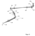
Figuren 4 und5 zeigen jeweils eine schematische Darstellung eines Teils des optischen Systems der Lichtblattmikroskope 100, 200 gemäß denFiguren 1 und2 . Der Übersicht halber sind die Beleuchtungseinheit 104, 202 und das Strahlteilerelement 206 in denFiguren 4 und5 jeweils weggelassen. In denFiguren 4 und5 sind Lichtbündel 400, 402 achsferner und achsnaher Strahlen durch unterschiedliche Schraffur dargestellt. Das Lichtbündel 400 achsferner Strahlen entspricht dabei dem Lichtblatt, das ja gerade mit Parallelversatz zur optischen Achse O2 der Transportoptik 106, 204 erzeugt wird. - In
Figur 4 ist ein Betriebszustand gezeigt, in dem durch das Wechselsystem 132 das erste Lichtumlenkelement 404 in den Strahlengang der Transportoptik 106, 204 eingebracht ist. Das erste Lichtumlenkelement 404 ist beispielhaft als Prisma ausgebildet. Das erste Lichtumlenkelement 404 bewirkt die erste Bildumkehr, d.h. das Umlenken der optischen Achse O2 der Transportoptik 106, 204 um 90° in Richtung der Eintrittspupille 406 des Objektivs 128. InFigur 4 ist deutlich zu erkennen, dass der Parallelversatz des Lichtblattes gegenüber der optischen Achse O2 der Transportoptik 106, 204 dazu führt, dass das Lichtblatt gegenüber der Mitte der Eintrittspupille 406 des Objektivs 128 seitlich versetzt in die Eintrittspupille 406 eintritt. In dem Beispiel nachFigur 4 tritt das Lichtblatt von der Transportoptik 106, 204 her gesehen links der Mitte in die Eintrittspupille 406 des Objektivs 128 ein. - In
Figur 5 ist ein Betriebszustand gezeigt, in dem durch das Wechselsystem 132 das zweite Lichtumlenkelement 500 in den Strahlengang der Transportoptik 106 eingebracht Das zweite Lichtumlenkelement 500 ist beispielhaft als Amici-Dachkant-Prisma ausgebildet. Das zweite Lichtumlenkelement 500 bewirkt sowohl die erste Bildumkehr als auch die zweite Bildumkehr, d.h. das Vertauschen von links und rechts in dem virtuellen Bild. Dieses Vertauschen führt dazu, dass das Lichtblatt in dem Betriebszustand nachFigur 5 in einen anderen Teilbereich der Eintrittspupille 406 des Objektivs 128 eintritt, als in dem Betriebszustand nachFigur 4 , in dem das erste Lichtumlenkelement 404 in den Strahlengang der Transportoptik 106, 204 eingebracht ist. In dem Besipiel nachFigur 5 tritt das Lichtblatt von der Transportoptik 106, 204 her gesehen rechts der Mitte in die Eintrittspupille 406 des Objektivs 128 ein. - In der Zusammenschau der
Figuren 4 und5 ist zu sehen, wie mit Hilfe des Wechselsystems 132 gesteuert werden kann, in welchen Teilbereich der Eintrittspupille 406 des Objektivs 128 das Lichtblatt eintritt. Das Objektiv 128 bewirkt in beiden Fällen eine Ablenkung des Lichtblatts in Richtung der optischen Achse des Objektivs 128. Folglich kann mittels des Wechselsystems 132 durch wahlweises Einbringen eines der beiden Lichtumlenkelemente 404, 500 bestimmt werden, aus welcher Richtung die Probe 130 mit dem Lichtblatt beleuchtet wird. - Die
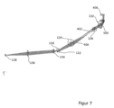
Figuren 6 und7 zeigen jeweils eine schematische Darstellung eines Teils des optischen Systems des Lichtblattmikroskops 300 gemäßFigur 3 . Der Übersicht halber ist die Beleuchtungseinheit 104 in denFiguren 6 und7 jeweils weggelassen. In denFiguren 6 und7 sind Lichtbündel achsferner und achsnaher Strahlen 400, 402 durch unterschiedliche Schraffur dargestellt. Das Lichtbündel 400 achsferner Strahlen entspricht dabei wiederum dem Lichtblatt. Im Gegensatz zu dem optischen System gemäß den Figuren 4 und 6 weist das in denFiguren 6 und7 gezeigte optische System keinen Rasterspiegel auf. Hierdurch kann auf die beiden Okulare 122, 124 verzichtet werden. -
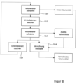
Figur 8 zeigt den Ablaufplan eines beispielhaften Verfahrens zum Erzeugen eines Volumenbildes der Probe 130 mittels des Lichtblattmikroskops gemäß einer derFiguren 1 bis 3 . - In Schritt S10 wird ein erstes Volumenbild erzeugt. Hierzu werden mittels der Abtastvorrichtung 102 sukzessive mehrere längs der Abtastrichtung aufeinanderfolgende Probenebenen mit dem Lichtblatt beleuchtet. Dabei erzeugt die Detektionsoptik 108 jeweils ein Schichtbild, indem sie ein in dem Zwischenbildraum 112 erzeugtes Bild der jeweils beleuchteten Probenebene auf den Bildsensor 138 abbildet. Die einzelnen Schichtbilder werden zu einem Schichtbildstapel zusammengesetzt, der dann zu dem Volumenbild weiterverarbeitet wird.
- In Schritt S12 wird dann mittels des Wechselsystems 132 das Lichtumlenkelement 404, 500, das sich gerade in dem Strahlengang der Transportoptik 106, 204, 302 befindet, gegen das andere Lichtumlenkelement 500 bzw. 404 ausgetauscht. Hierdurch werden die Beleuchtungsrichtung und die Detektionsrichtung des Lichtblattmikroskops 100, 200, 300 umgeschaltet.
- In Schritt S14 werden die in Schritt S10 durchgeführten Schritte zum Erzeugen des ersten Volumenbildes wiederholt, um ein zweites Volumenbild zu erzeugen. Das zweite Volumenbild unterscheidet sich von dem ersten Volumenbild in der Beleuchtungsrichtung, aus der die Probenebenen mit dem Lichtblatt beleuchtet werden, und der Detektionsrichtung, in der diese Probenebenen auf den Bildsensor 138 abgebildet werden.
- In Schritt S16 werden die beiden Volumenbilder zu einem einzigen hochaufgelösten Volumenbild verrechnet. Alternativ oder zusätzlich wird auf den Schritt S14 folgend das in dem Strahlengang der Transportoptik 106, 204, 302 befindliche Lichtumlenkelement 500, 404 mittels des Wechselsystems 132 gegen das andere Lichtumlenkelement 404 bzw. 500 ausgetaucht, und es werden die Schritte S10 bis S14 wiederholt. Hierdurch kann eine Zeitreihe von Volumenbildern erzeugt werden.
- Der Begriff "und/oder" umfasst alle Kombinationen von einem oder mehreren der zugehörigen aufgeführten Elemente und kann mit "/" abgekürzt werden.
- Obwohl einige Aspekte im Rahmen einer Vorrichtung beschrieben wurden, ist es klar, dass diese Aspekte auch eine Beschreibung des entsprechenden Verfahrens darstellen, wobei ein Block oder eine Vorrichtung einem Verfahrensschritt oder einer Funktion eines Verfahrensschritts entspricht. Analog dazu stellen Aspekte, die im Rahmen eines Verfahrensschritts beschrieben werden, auch eine Beschreibung eines entsprechenden Blocks oder Elements oder einer Eigenschaft einer entsprechenden Vorrichtung dar.
-
- 100
- Lichtblattmikroskop
- 102
- Abtastvorrichtung
- 104
- Beleuchtungseinheit
- 106
- Transportoptik
- 108
- Detektionsoptik
- 110
- Prozessor
- 112
- Zwischenbildraum
- 114
- Lichtquelle
- 116
- Beleuchtungsobjektiv
- 118
- Projektionsobjektiv
- 120
- Tubuslinse
- 122,124
- Okular
- 126
- Tubuslinse
- 128
- Objektiv
- 130
- Probe
- 132
- Wechselsystem
- 134
- Detektionsobjektiv
- 136
- Tubuslinse
- 138
- Bildsensor
- 200
- Lichtblattmikroskop
- 202
- Beleuchtungseinheit
- 204
- Transportoptik
- 206
- Strahlteilerelement
- 300
- Lichtblattmikroskop
- 302
- Transportoptik
- 304
- Projektionsobjektiv
- 306
- Fokussiereinrichtung
- 308
- Prozessor
- 400,402
- Strahlbündel
- 404
- Lichtumlenkelement
- 406
- Eintrittspupille
- 500
- Lichtumlenkelement
- O1, O2, O3
- Optische Achse
Claims (14)
- Optisches System für ein Lichtblattmikroskop (100, 200, 300), mit einer Transportoptik (106, 204, 302), die ausgebildet ist, ein Lichtblatt zum Beleuchten einer schräg zur optischen Achse der Transportoptik (106, 204, 302) liegenden Probenebene in eine Probe (130) abzubilden und die beleuchtete Probenebene in einen Zwischenbildraum (112) abzubilden, undmit einer Detektionsoptik (108), deren optische Achse gegenüber der optischen Achse der Transportoptik (106, 204, 302) um eine Kippachse verkippt ist, die durch den Zwischenbildraum (112) verläuft,dadurch gekennzeichnet, dass die Transportoptik (106, 204, 302) ein Wechselsystem (132) umfasst, das mindestens ein erstes und ein zweites Lichtumlenkelement (404, 500) hat und ausgebildet ist, eine Beleuchtungsrichtung, längs der das Lichtblatt die Probe (130) beleuchtet, umzuschalten, indem das erste und das zweite Lichtumlenkelement (404, 500) abwechselnd in einen Strahlengang der Transportoptik (106, 204, 302) eingebracht werden, unddas erste Lichtumlenkelement (404) eine teilweise Bildumkehr in nur einer Richtung bewirkt und das zweite Lichtumlenkelement (500) eine vollständige Bildumkehr in zwei Richtungen bewirkt.
- Optisches System nach Anspruch 1, wobei die Transportoptik (106, 204, 302) ausgebildet ist, das in dem Zwischenbildraum (112) erzeugte Lichtblatt zum Beleuchten der schräg zur optischen Achse der Transportoptik (106, 204, 302) liegenden Probenebenen in die Probe (130) abzubilden.
- Optisches System nach einem der vorhergehenden Ansprüche, mit einer Abtastvorrichtung (102, 306) zum schrittweisen Beleuchten mehrerer längs einer Abtastrichtung aufeinanderfolgender Probenebenen mit dem Lichtblatt, wobei die Detektionsoptik (108) ausgebildet ist, jeweils ein Schichtbild aus einem in dem Zwischenbildraum (112) erzeugten Bild der jeweiligen Probenebene zu erzeugen.
- Optisches System nach Anspruch 3, wobei die Abtastvorrichtung (102) mindestens einen Rasterspiegel umfasst, durch welchen das Lichtblatt quer zur optischen Achse der Transportoptik (106, 204) bewegbar ist.
- Optisches System nach Anspruch 3, wobei die Abtastvorrichtung (306) mindestens eine Fokussiereinrichtung zum Einstellen einer Schärfeebene der Transportoptik (302) umfasst.
- Optisches System nach einem der Ansprüche 3 bis 5, mit einer Bildverarbeitungs- und Steuereinheit (110, 308), die ausgebildet ist, das erste Lichtumlenkelement (404) in den Strahlengang der Transportoptik (106, 204, 302) einzubringen, einen ersten Bilddatensatz zu erzeugen, der einen aus den Schichtbildern zusammengesetzten Schichtbildstapel darstellt, das zweite Lichtumlenkelement (500) in den Strahlengang der Transportoptik (106, 204, 302) einzubringen, einen zweiten Bilddatensatz zu erzeugen, der einen weiteren aus den Schichtbildern zusammengesetzten Schichtbildstapel darstellt, und den ersten Bilddatensatz und den zweiten Bilddatensatz zu einem Volumenbild der Probe (130) zu verarbeiten.
- Optisches System nach einem der vorhergehenden Ansprüche, wobei die Transportoptik (106, 204, 302) ein einziges der Probe (130) zugewandtes Objektiv (128) hat, dessen optische Achse parallel zu der Kippachse ist.
- Optisches System nach einem der vorhergehenden Ansprüche, wobei das erste Lichtumlenkelement (404) und das zweite Lichtumlenkelement (500) den Strahlengang der Transportoptik (106, 204, 302) jeweils um 90° ablenken.
- Optisches System nach einem der vorhergehenden Ansprüche, wobei das erste Lichtumlenkelement (404) ein Umlenkspiegel oder ein Umlenkprisma ist.
- Optisches System nach einem der vorhergehenden Ansprüche, wobei das zweite Lichtumlenkelement (500) ein Dachkantprisma, ein Dachkantspiegel oder ein Amici-Prisma ist.
- Optisches System nach einem der vorhergehenden Ansprüche, wobei das zweite Lichtumlenkelement (500) eine Bilddrehung um 90°, 180° oder 270° bewirkt.
- Lichtblattmikroskop (100, 200, 300) mit einem optischen System nach einem der vorhergehenden Ansprüche.
- Lichtblattmikroskop (100, 200, 300) nach Anspruch 12, wobei das Lichtblattmikroskop (100, 200, 300) ein inverses Mikroskop ist.
- Verfahren zum Beleuchten einer Probe (130) in einem Lichtblattmikroskop (100, 200, 300), bei demmittels einer Transportoptik (106, 204, 302) ein Lichtblatt zum Beleuchten einer schräg zur optischen Achse der Transportoptik (106, 204, 302) liegenden Probenebenen in eine Probe (130) abgebildet wird und die beleuchtete Probenebene in einen Zwischenbildraum (112) abgebildet wird,dadurch gekennzeichnmet, dass eine Beleuchtungsrichtung, längs der das Lichtblatt die Probe (130) beleuchtet, umgeschaltet wird, indem ein erstes und ein zweites Lichtumlenkelement (404, 500) abwechselnd in einen Strahlengang der Transportoptik (106, 204, 302) eingebracht werden,wobei das erste Lichtumlenkelement (404) eine teilweise Bildumkehr in nur einer Richtung bewirkt und das zweite Lichtumlenkelement (404, 500) eine vollständige Bildumkehr in zwei Richtungen bewirkt.
Applications Claiming Priority (2)
| Application Number | Priority Date | Filing Date | Title |
|---|---|---|---|
| DE102019128681.6A DE102019128681A1 (de) | 2019-10-23 | 2019-10-23 | Optisches System für ein Lichtblattmikroskop |
| PCT/EP2020/079681 WO2021078825A1 (de) | 2019-10-23 | 2020-10-22 | Optisches system für ein lichtblattmikroskop |
Publications (2)
| Publication Number | Publication Date |
|---|---|
| EP4049079A1 EP4049079A1 (de) | 2022-08-31 |
| EP4049079B1 true EP4049079B1 (de) | 2025-01-08 |
Family
ID=73449010
Family Applications (1)
| Application Number | Title | Priority Date | Filing Date |
|---|---|---|---|
| EP20807289.2A Active EP4049079B1 (de) | 2019-10-23 | 2020-10-22 | Optisches system für ein lichtblattmikroskop |
Country Status (4)
| Country | Link |
|---|---|
| US (1) | US12332417B2 (de) |
| EP (1) | EP4049079B1 (de) |
| DE (1) | DE102019128681A1 (de) |
| WO (1) | WO2021078825A1 (de) |
Families Citing this family (3)
| Publication number | Priority date | Publication date | Assignee | Title |
|---|---|---|---|---|
| DE102020128524A1 (de) * | 2020-10-29 | 2022-05-05 | Carl Zeiss Microscopy Gmbh | Lichtblattmikroskop und Verfahren der Lichtblattmikroskopie |
| US12422661B2 (en) * | 2023-01-27 | 2025-09-23 | POSTECH Research and Business Development Foundation | Photographing apparatus and photographing method |
| WO2025144932A1 (en) * | 2023-12-26 | 2025-07-03 | Molecular Devices, Llc | Imager with image rotation |
Family Cites Families (11)
| Publication number | Priority date | Publication date | Assignee | Title |
|---|---|---|---|---|
| DE3615842A1 (de) | 1986-05-10 | 1987-11-12 | Moeller J D Optik | Zwischenbaugruppe fuer ein stereoskopisches operationsmikroskop fuer die augenchirurgie |
| DE102004050893B4 (de) | 2003-10-31 | 2015-05-21 | Carl Zeiss Meditec Ag | Tubus mit zwei umschaltbaren Planoptikelementen zur wahlweisen Strahlengangvertauschung und Bildumkehr für ein Mikroskop sowie Mikroskop |
| GB0814039D0 (en) | 2008-07-31 | 2008-09-10 | Imp Innovations Ltd | Optical arrangement for oblique plane microscopy |
| US10061111B2 (en) * | 2014-01-17 | 2018-08-28 | The Trustees Of Columbia University In The City Of New York | Systems and methods for three dimensional imaging |
| DE102014102215A1 (de) | 2014-02-20 | 2015-08-20 | Carl Zeiss Microscopy Gmbh | Verfahren und Anordnung zur Lichtblattmikroskopie |
| DE102015209756A1 (de) | 2015-05-28 | 2016-12-01 | Carl Zeiss Microscopy Gmbh | Anordnung und Verfahren zur Lichtblattmikroskopie |
| DE102016103182B4 (de) | 2016-02-23 | 2018-04-12 | Leica Microsystems Cms Gmbh | Lichtblattmikroskop und Verfahren zur lichtmikroskopischen Abbildung einer Probe |
| WO2018052905A1 (en) * | 2016-09-16 | 2018-03-22 | The Trustees Of Columbia University In The City Of New York | Three-dimensional imaging using swept, confocally aligned planar excitation and a customized image splitter |
| DE102016119268B3 (de) * | 2016-10-10 | 2017-12-21 | Leica Microsystems Cms Gmbh | Schiefebenenmikroskop |
| DE102017116380B3 (de) | 2017-07-20 | 2018-12-20 | Leica Microsystems Cms Gmbh | Lichtblattmikroskopisches Verfahren zur Erzeugung eines Volumenbildes einer Probe und Lichtblattmikroskop |
| DE102018204940B4 (de) | 2018-03-29 | 2023-03-30 | Leica Microsystems Cms Gmbh | Optisches System mit verkippter Beleuchtungsebene und Verfahren zum Beleuchten eines Probenvolumens in einem optischen System mit verkippter Beleuchtungsebene |
-
2019
- 2019-10-23 DE DE102019128681.6A patent/DE102019128681A1/de not_active Withdrawn
-
2020
- 2020-10-22 US US17/770,321 patent/US12332417B2/en active Active
- 2020-10-22 EP EP20807289.2A patent/EP4049079B1/de active Active
- 2020-10-22 WO PCT/EP2020/079681 patent/WO2021078825A1/de not_active Ceased
Also Published As
| Publication number | Publication date |
|---|---|
| US12332417B2 (en) | 2025-06-17 |
| WO2021078825A1 (de) | 2021-04-29 |
| DE102019128681A1 (de) | 2021-04-29 |
| EP4049079A1 (de) | 2022-08-31 |
| US20220390730A1 (en) | 2022-12-08 |
Similar Documents
| Publication | Publication Date | Title |
|---|---|---|
| DE102018210603B4 (de) | Verfahren zum Erzeugen eines Übersichtsbilds unter Verwendung eines hochaperturigen Objektivs | |
| EP2885669B1 (de) | Optische anordnung und ein mikroskop | |
| EP2887117B1 (de) | Mikroskop und Verfahren zur SPIM Mikroskopie | |
| DE102016119268B3 (de) | Schiefebenenmikroskop | |
| DE10063276C2 (de) | Scanmikroskop | |
| DE112011104595B4 (de) | Vorrichtung mit einem geladenen Teilchenstrahl sowie Verfahren zur Steuerung | |
| DE102017214189A1 (de) | Verfahren zum Betrieb einer Mikroskopieranordnung und Mikroskopieranordnung mit einem ersten Mikroskop und mindestens einem weiteren Mikroskop | |
| EP4049079A1 (de) | Optisches system für ein lichtblattmikroskop | |
| DE102023005252A1 (de) | Mikroskop mit schneller quasikonfokaler Detektion | |
| EP3440492B1 (de) | Verfahren und mikroskop zum untersuchen einer probe | |
| DE102017116380B3 (de) | Lichtblattmikroskopisches Verfahren zur Erzeugung eines Volumenbildes einer Probe und Lichtblattmikroskop | |
| DE102016100252A1 (de) | Projektionssystem für Displayanwendungen | |
| DE102014118025B4 (de) | Vorrichtung zur Lichtblattmikroskopie | |
| DE102016117675B4 (de) | Mikroskop mit einem Beleuchtungsmodul | |
| EP1211542B1 (de) | Anordnung zur visuellen und quantitativen 3-D-Untersuchung von Proben | |
| DE10058100B4 (de) | Verfahren und eine Anordnung zur Abtastung mikroskopischer Objekte mit einer Scaneinrichtung | |
| EP3516440B1 (de) | Mikroskopsystem | |
| DE102016108384B3 (de) | Vorrichtung und Verfahren zur lichtblattartigen Beleuchtung einer Probe | |
| DE102014017003A1 (de) | Scaneinrichtung zur 3D-Positionierung von Laserspots | |
| WO2013045065A1 (de) | Laser-scanning-mikroskop | |
| DE102016120312B3 (de) | Verfahren zum Beleuchten von Fokuspositionen objektseitig eines Objektivs eines Mikroskops und Mikroskop | |
| DE102017103252B3 (de) | Verfahren zur mikroskopischen Rasterbeleuchtung | |
| DE102015100695A1 (de) | Optische Anordnung für ein Laser-Scanner-System | |
| DE102024205124A1 (de) | Scanmikroskop und dessen Verwendung | |
| DE102015011135B3 (de) | Stereo-Mikroskopiesystem mit gemeinsam genutztem Bildsensor und drehbaren Teilbild-Objektiven |
Legal Events
| Date | Code | Title | Description |
|---|---|---|---|
| STAA | Information on the status of an ep patent application or granted ep patent |
Free format text: STATUS: UNKNOWN |
|
| STAA | Information on the status of an ep patent application or granted ep patent |
Free format text: STATUS: THE INTERNATIONAL PUBLICATION HAS BEEN MADE |
|
| PUAI | Public reference made under article 153(3) epc to a published international application that has entered the european phase |
Free format text: ORIGINAL CODE: 0009012 |
|
| STAA | Information on the status of an ep patent application or granted ep patent |
Free format text: STATUS: REQUEST FOR EXAMINATION WAS MADE |
|
| 17P | Request for examination filed |
Effective date: 20220331 |
|
| AK | Designated contracting states |
Kind code of ref document: A1 Designated state(s): AL AT BE BG CH CY CZ DE DK EE ES FI FR GB GR HR HU IE IS IT LI LT LU LV MC MK MT NL NO PL PT RO RS SE SI SK SM TR |
|
| DAV | Request for validation of the european patent (deleted) | ||
| DAX | Request for extension of the european patent (deleted) | ||
| P01 | Opt-out of the competence of the unified patent court (upc) registered |
Effective date: 20230414 |
|
| GRAP | Despatch of communication of intention to grant a patent |
Free format text: ORIGINAL CODE: EPIDOSNIGR1 |
|
| STAA | Information on the status of an ep patent application or granted ep patent |
Free format text: STATUS: GRANT OF PATENT IS INTENDED |
|
| INTG | Intention to grant announced |
Effective date: 20240823 |
|
| GRAS | Grant fee paid |
Free format text: ORIGINAL CODE: EPIDOSNIGR3 |
|
| GRAA | (expected) grant |
Free format text: ORIGINAL CODE: 0009210 |
|
| STAA | Information on the status of an ep patent application or granted ep patent |
Free format text: STATUS: THE PATENT HAS BEEN GRANTED |
|
| AK | Designated contracting states |
Kind code of ref document: B1 Designated state(s): AL AT BE BG CH CY CZ DE DK EE ES FI FR GB GR HR HU IE IS IT LI LT LU LV MC MK MT NL NO PL PT RO RS SE SI SK SM TR |
|
| REG | Reference to a national code |
Ref country code: GB Ref legal event code: FG4D Free format text: NOT ENGLISH |
|
| REG | Reference to a national code |
Ref country code: CH Ref legal event code: EP |
|
| REG | Reference to a national code |
Ref country code: DE Ref legal event code: R096 Ref document number: 502020010171 Country of ref document: DE |
|
| REG | Reference to a national code |
Ref country code: IE Ref legal event code: FG4D Free format text: LANGUAGE OF EP DOCUMENT: GERMAN |
|
| REG | Reference to a national code |
Ref country code: LT Ref legal event code: MG9D |
|
| REG | Reference to a national code |
Ref country code: NL Ref legal event code: MP Effective date: 20250108 |
|
| PG25 | Lapsed in a contracting state [announced via postgrant information from national office to epo] |
Ref country code: NL Free format text: LAPSE BECAUSE OF FAILURE TO SUBMIT A TRANSLATION OF THE DESCRIPTION OR TO PAY THE FEE WITHIN THE PRESCRIBED TIME-LIMIT Effective date: 20250108 |
|
| PG25 | Lapsed in a contracting state [announced via postgrant information from national office to epo] |
Ref country code: RS Free format text: LAPSE BECAUSE OF FAILURE TO SUBMIT A TRANSLATION OF THE DESCRIPTION OR TO PAY THE FEE WITHIN THE PRESCRIBED TIME-LIMIT Effective date: 20250408 |
|
| PG25 | Lapsed in a contracting state [announced via postgrant information from national office to epo] |
Ref country code: FI Free format text: LAPSE BECAUSE OF FAILURE TO SUBMIT A TRANSLATION OF THE DESCRIPTION OR TO PAY THE FEE WITHIN THE PRESCRIBED TIME-LIMIT Effective date: 20250108 |
|
| PG25 | Lapsed in a contracting state [announced via postgrant information from national office to epo] |
Ref country code: PL Free format text: LAPSE BECAUSE OF FAILURE TO SUBMIT A TRANSLATION OF THE DESCRIPTION OR TO PAY THE FEE WITHIN THE PRESCRIBED TIME-LIMIT Effective date: 20250108 |
|
| PG25 | Lapsed in a contracting state [announced via postgrant information from national office to epo] |
Ref country code: ES Free format text: LAPSE BECAUSE OF FAILURE TO SUBMIT A TRANSLATION OF THE DESCRIPTION OR TO PAY THE FEE WITHIN THE PRESCRIBED TIME-LIMIT Effective date: 20250108 |
|
| PG25 | Lapsed in a contracting state [announced via postgrant information from national office to epo] |
Ref country code: NO Free format text: LAPSE BECAUSE OF FAILURE TO SUBMIT A TRANSLATION OF THE DESCRIPTION OR TO PAY THE FEE WITHIN THE PRESCRIBED TIME-LIMIT Effective date: 20250408 Ref country code: IS Free format text: LAPSE BECAUSE OF FAILURE TO SUBMIT A TRANSLATION OF THE DESCRIPTION OR TO PAY THE FEE WITHIN THE PRESCRIBED TIME-LIMIT Effective date: 20250508 |
|
| PG25 | Lapsed in a contracting state [announced via postgrant information from national office to epo] |
Ref country code: HR Free format text: LAPSE BECAUSE OF FAILURE TO SUBMIT A TRANSLATION OF THE DESCRIPTION OR TO PAY THE FEE WITHIN THE PRESCRIBED TIME-LIMIT Effective date: 20250108 |
|
| PG25 | Lapsed in a contracting state [announced via postgrant information from national office to epo] |
Ref country code: PT Free format text: LAPSE BECAUSE OF FAILURE TO SUBMIT A TRANSLATION OF THE DESCRIPTION OR TO PAY THE FEE WITHIN THE PRESCRIBED TIME-LIMIT Effective date: 20250508 Ref country code: LV Free format text: LAPSE BECAUSE OF FAILURE TO SUBMIT A TRANSLATION OF THE DESCRIPTION OR TO PAY THE FEE WITHIN THE PRESCRIBED TIME-LIMIT Effective date: 20250108 |
|
| PG25 | Lapsed in a contracting state [announced via postgrant information from national office to epo] |
Ref country code: GR Free format text: LAPSE BECAUSE OF FAILURE TO SUBMIT A TRANSLATION OF THE DESCRIPTION OR TO PAY THE FEE WITHIN THE PRESCRIBED TIME-LIMIT Effective date: 20250409 Ref country code: BG Free format text: LAPSE BECAUSE OF FAILURE TO SUBMIT A TRANSLATION OF THE DESCRIPTION OR TO PAY THE FEE WITHIN THE PRESCRIBED TIME-LIMIT Effective date: 20250108 |
|
| PG25 | Lapsed in a contracting state [announced via postgrant information from national office to epo] |
Ref country code: SE Free format text: LAPSE BECAUSE OF FAILURE TO SUBMIT A TRANSLATION OF THE DESCRIPTION OR TO PAY THE FEE WITHIN THE PRESCRIBED TIME-LIMIT Effective date: 20250108 |
|
| PG25 | Lapsed in a contracting state [announced via postgrant information from national office to epo] |
Ref country code: SM Free format text: LAPSE BECAUSE OF FAILURE TO SUBMIT A TRANSLATION OF THE DESCRIPTION OR TO PAY THE FEE WITHIN THE PRESCRIBED TIME-LIMIT Effective date: 20250108 |
|
| REG | Reference to a national code |
Ref country code: DE Ref legal event code: R097 Ref document number: 502020010171 Country of ref document: DE |
|
| PG25 | Lapsed in a contracting state [announced via postgrant information from national office to epo] |
Ref country code: DK Free format text: LAPSE BECAUSE OF FAILURE TO SUBMIT A TRANSLATION OF THE DESCRIPTION OR TO PAY THE FEE WITHIN THE PRESCRIBED TIME-LIMIT Effective date: 20250108 |
|
| PG25 | Lapsed in a contracting state [announced via postgrant information from national office to epo] |
Ref country code: EE Free format text: LAPSE BECAUSE OF FAILURE TO SUBMIT A TRANSLATION OF THE DESCRIPTION OR TO PAY THE FEE WITHIN THE PRESCRIBED TIME-LIMIT Effective date: 20250108 Ref country code: CZ Free format text: LAPSE BECAUSE OF FAILURE TO SUBMIT A TRANSLATION OF THE DESCRIPTION OR TO PAY THE FEE WITHIN THE PRESCRIBED TIME-LIMIT Effective date: 20250108 |
|
| PG25 | Lapsed in a contracting state [announced via postgrant information from national office to epo] |
Ref country code: RO Free format text: LAPSE BECAUSE OF FAILURE TO SUBMIT A TRANSLATION OF THE DESCRIPTION OR TO PAY THE FEE WITHIN THE PRESCRIBED TIME-LIMIT Effective date: 20250108 |
|
| PG25 | Lapsed in a contracting state [announced via postgrant information from national office to epo] |
Ref country code: SK Free format text: LAPSE BECAUSE OF FAILURE TO SUBMIT A TRANSLATION OF THE DESCRIPTION OR TO PAY THE FEE WITHIN THE PRESCRIBED TIME-LIMIT Effective date: 20250108 |
|
| PLBE | No opposition filed within time limit |
Free format text: ORIGINAL CODE: 0009261 |
|
| STAA | Information on the status of an ep patent application or granted ep patent |
Free format text: STATUS: NO OPPOSITION FILED WITHIN TIME LIMIT |
|
| 26N | No opposition filed |
Effective date: 20251009 |
|
| PGFP | Annual fee paid to national office [announced via postgrant information from national office to epo] |
Ref country code: DE Payment date: 20251028 Year of fee payment: 6 |
|
| PGFP | Annual fee paid to national office [announced via postgrant information from national office to epo] |
Ref country code: GB Payment date: 20251023 Year of fee payment: 6 |
|
| PGFP | Annual fee paid to national office [announced via postgrant information from national office to epo] |
Ref country code: FR Payment date: 20251027 Year of fee payment: 6 |
|
| PG25 | Lapsed in a contracting state [announced via postgrant information from national office to epo] |
Ref country code: IT Free format text: LAPSE BECAUSE OF FAILURE TO SUBMIT A TRANSLATION OF THE DESCRIPTION OR TO PAY THE FEE WITHIN THE PRESCRIBED TIME-LIMIT Effective date: 20250108 |