EP4048873B1 - Control schemes for thermal management of power production systems and methods - Google Patents
Control schemes for thermal management of power production systems and methods Download PDFInfo
- Publication number
- EP4048873B1 EP4048873B1 EP20800335.0A EP20800335A EP4048873B1 EP 4048873 B1 EP4048873 B1 EP 4048873B1 EP 20800335 A EP20800335 A EP 20800335A EP 4048873 B1 EP4048873 B1 EP 4048873B1
- Authority
- EP
- European Patent Office
- Prior art keywords
- heu
- stream
- turbine
- exhaust stream
- temperature
- Prior art date
- Legal status (The legal status is an assumption and is not a legal conclusion. Google has not performed a legal analysis and makes no representation as to the accuracy of the status listed.)
- Active
Links
Images

Classifications
-
- F—MECHANICAL ENGINEERING; LIGHTING; HEATING; WEAPONS; BLASTING
- F01—MACHINES OR ENGINES IN GENERAL; ENGINE PLANTS IN GENERAL; STEAM ENGINES
- F01K—STEAM ENGINE PLANTS; STEAM ACCUMULATORS; ENGINE PLANTS NOT OTHERWISE PROVIDED FOR; ENGINES USING SPECIAL WORKING FLUIDS OR CYCLES
- F01K25/00—Plants or engines characterised by use of special working fluids, not otherwise provided for; Plants operating in closed cycles and not otherwise provided for
- F01K25/08—Plants or engines characterised by use of special working fluids, not otherwise provided for; Plants operating in closed cycles and not otherwise provided for using special vapours
- F01K25/10—Plants or engines characterised by use of special working fluids, not otherwise provided for; Plants operating in closed cycles and not otherwise provided for using special vapours the vapours being cold, e.g. ammonia, carbon dioxide, ether
- F01K25/103—Carbon dioxide
-
- B—PERFORMING OPERATIONS; TRANSPORTING
- B01—PHYSICAL OR CHEMICAL PROCESSES OR APPARATUS IN GENERAL
- B01D—SEPARATION
- B01D53/00—Separation of gases or vapours; Recovering vapours of volatile solvents from gases; Chemical or biological purification of waste gases, e.g. engine exhaust gases, smoke, fumes, flue gases, aerosols
- B01D53/34—Chemical or biological purification of waste gases
- B01D53/46—Removing components of defined structure
- B01D53/54—Nitrogen compounds
- B01D53/58—Ammonia
-
- B—PERFORMING OPERATIONS; TRANSPORTING
- B01—PHYSICAL OR CHEMICAL PROCESSES OR APPARATUS IN GENERAL
- B01D—SEPARATION
- B01D53/00—Separation of gases or vapours; Recovering vapours of volatile solvents from gases; Chemical or biological purification of waste gases, e.g. engine exhaust gases, smoke, fumes, flue gases, aerosols
- B01D53/34—Chemical or biological purification of waste gases
- B01D53/92—Chemical or biological purification of waste gases of engine exhaust gases
- B01D53/94—Chemical or biological purification of waste gases of engine exhaust gases by catalytic processes
- B01D53/9445—Simultaneously removing carbon monoxide, hydrocarbons or nitrogen oxides making use of three-way catalysts [TWC] or four-way-catalysts [FWC]
-
- F—MECHANICAL ENGINEERING; LIGHTING; HEATING; WEAPONS; BLASTING
- F02—COMBUSTION ENGINES; HOT-GAS OR COMBUSTION-PRODUCT ENGINE PLANTS
- F02C—GAS-TURBINE PLANTS; AIR INTAKES FOR JET-PROPULSION PLANTS; CONTROLLING FUEL SUPPLY IN AIR-BREATHING JET-PROPULSION PLANTS
- F02C3/00—Gas-turbine plants characterised by the use of combustion products as the working fluid
- F02C3/34—Gas-turbine plants characterised by the use of combustion products as the working fluid with recycling of part of the working fluid, i.e. semi-closed cycles with combustion products in the closed part of the cycle
-
- F—MECHANICAL ENGINEERING; LIGHTING; HEATING; WEAPONS; BLASTING
- F02—COMBUSTION ENGINES; HOT-GAS OR COMBUSTION-PRODUCT ENGINE PLANTS
- F02C—GAS-TURBINE PLANTS; AIR INTAKES FOR JET-PROPULSION PLANTS; CONTROLLING FUEL SUPPLY IN AIR-BREATHING JET-PROPULSION PLANTS
- F02C6/00—Plural gas-turbine plants; Combinations of gas-turbine plants with other apparatus; Adaptations of gas-turbine plants for special use
- F02C6/18—Plural gas-turbine plants; Combinations of gas-turbine plants with other apparatus; Adaptations of gas-turbine plants for special use using the waste heat of gas-turbine plants outside the plants themselves, e.g. gas-turbine power heat plants
-
- F—MECHANICAL ENGINEERING; LIGHTING; HEATING; WEAPONS; BLASTING
- F05—INDEXING SCHEMES RELATING TO ENGINES OR PUMPS IN VARIOUS SUBCLASSES OF CLASSES F01-F04
- F05D—INDEXING SCHEME FOR ASPECTS RELATING TO NON-POSITIVE-DISPLACEMENT MACHINES OR ENGINES, GAS-TURBINES OR JET-PROPULSION PLANTS
- F05D2210/00—Working fluids
- F05D2210/10—Kind or type
- F05D2210/12—Kind or type gaseous, i.e. compressible
-
- Y—GENERAL TAGGING OF NEW TECHNOLOGICAL DEVELOPMENTS; GENERAL TAGGING OF CROSS-SECTIONAL TECHNOLOGIES SPANNING OVER SEVERAL SECTIONS OF THE IPC; TECHNICAL SUBJECTS COVERED BY FORMER USPC CROSS-REFERENCE ART COLLECTIONS [XRACs] AND DIGESTS
- Y02—TECHNOLOGIES OR APPLICATIONS FOR MITIGATION OR ADAPTATION AGAINST CLIMATE CHANGE
- Y02E—REDUCTION OF GREENHOUSE GAS [GHG] EMISSIONS, RELATED TO ENERGY GENERATION, TRANSMISSION OR DISTRIBUTION
- Y02E20/00—Combustion technologies with mitigation potential
- Y02E20/14—Combined heat and power generation [CHP]
Definitions
- Provision of clean CO 2 for uses such as noted above typically includes separation of the CO 2 from an industrial gas mixture, which mixture often contains further compounds, such as CO, H 2 , sulfur, and the like. This, of course, requires a series of purification processes.
- the purification requirements as well as the need for providing the CO 2 at the desired pressure and/or temperature can entail procuring dedicated compression, cleanup, and heating equipment that leads to high capital costs and large energy consumptions.
- power production processes are typically configured for utilization and production of significant amounts of thermal energy.
- This thermal energy may be utilized directly in power production or may be available for further uses.
- there is a need for means for controlling power production processes such that various product flows, such as carbon dioxide and modes of thermal transfer, may be efficiently obtained and/or exported for a further use.
- the present disclosure thus provides to systems and methods whereby CO 2 arising from a power production cycle utilizing CO 2 as a working fluid can be taken as an end product and fed directly into a further downstream use of the material.
- the systems and methods of the present disclosure can allow for the export of CO 2 as a chemical feedstock and/or heat transfer fluid at various temperatures and pressures for use in downstream endothermic industrial processes.
- the presently disclosed systems and methods are beneficial in that low-grade heat can be provided to an external process. This may be accomplished in an example embodiment by using combustion-derived CO 2 effectively as a heat carrier.
- the present disclosure provides for management of plant turndown (i.e. turbine stability and operability) through the export of said low-grade heat along with changes to the flow rate through the hot gas compressor ("HGC") of the power production system from which the CO 2 is derived.
- HGC hot gas compressor
- the maximum temperature can be limited by the total heat quality and quantity that can be taken from the recuperative heat exchanger train utilized in the power production cycle before the hot gas compressor can no longer supplement the losses (i.e. maintain heat exchanger profile).
- the systems and methods of the present disclosure can provide distinct advantages over other possible industrial sources of CO 2 , such as systems wherein CO 2 compression heat is recovered in order to help generate steam that is used to strip CO 2 from recovery columns.
- the heat recovery process is an add-on independent of direct power generation activities and thus cannot provide many of the advantages of the presently disclosed systems and methods.
- known systems and methods do not include using combustion derived CO 2 taken from a supercritical CO 2 power production cycle, and likewise do not contemplate supplying external thermal energy for chemical processes by using CO 2 as a transportable heat sink.
- the pressure can be about 2 bar to about 500 bar, about 10 bar to about 490 bar, about 25 bar to about 480 bar, about 50 bar to about 475 bar, about 75 bar to about 450 bar, or about 100 bar to about 400 bar.
- Exported CO 2 can be at a temperature of about 35 °C or greater, about 40 °C or greater, about 50 °C or greater, about 75 °C or greater, or about 100 °C or greater (said export temperature having an upper limit in line with temperature limits inherent to the equipment required handling of the CO 2 ).
- the temperature can be about 35 °C to about 500 °C, about 40 °C to about 450 °C, about 50 °C to about 400 °C, or about 60 °C to about 350 °C.
- the present disclosure can relate to a control system suitable for use in a power production plant.
- the power production plant can be a plant burning a fuel in substantially pure oxygen in a combustor at a pressure of about 12 MPa or greater with an additional circulating CO 2 stream to produce a combined stream of combustion products and circulating CO 2 .
- the combined stream can be passed through a power producing turbine with a discharge pressure of at least 10 bar.
- the turbine exhaust can be cooled in an economizer heat exchange to preheat the circulating CO 2 stream.
- the turbine exhaust can be further cooled to near ambient temperature, and condensed water can be removed.
- the CO 2 gas stream can be compressed to be at or near the turbine inlet pressure using a gas compressor followed by a dense CO 2 pump to form the circulating CO 2 stream. Net CO 2 produced in the combustor can be removed at any pressure between the turbine inlet and outlet pressures.
- the difference between the temperature of the turbine exhaust entering the economizer heat exchanger and the temperature of the circulating CO 2 stream leaving the economizer heat exchange can be controlled to be at or below 50°C by controlling the flow rate of a portion of the circulating CO 2 stream which is heated by an added heat source.
- the flow rate of net liquid water and fuel derived impurities removed from the system can be controlled by the level in the liquid water separator.
- the oxygen flow rate can be controlled to maintain a ratio of oxygen to fuel gas flow rate which can result in a defined excess oxygen in the turbine inlet flow to ensure complete fuel gas combustion and oxidation of components in the fuel gas.
- the oxygen stream at CO 2 compressor inlet pressure can be mixed with a quantity of CO 2 from the CO 2 compressor inlet to produce an oxidant stream with an oxygen composition of about 15% to about 40% (molar), which can lower the adiabatic flame temperature in the combustor.
- the oxidant flow required to produce the required oxygen to fuel gas ratio can be controlled by the speed of the oxidant pump.
- the discharge pressure of the oxidant compressor can be controlled by recycling compressed oxidant flow to the compressor inlet.
- the inlet pressure of the oxidant compressor can be controlled by the flow rate of diluent CO 2 mixed with the oxygen which forms the oxidant stream.
- the ratio of oxygen to CO 2 in the oxidant stream can be controlled by the flow of oxygen.
- the oxygen can be delivered to the power system at a pressure at least as high as the turbine inlet pressure and where an oxidant stream with an oxygen composition in the range of about 15% to about 40% (molar) can be desired.
- the oxygen to fuel gas ratio can be controlled by the oxygen flow.
- the oxygen to CO 2 ratio in the oxidant flow can be controlled by the flow of diluent CO 2 taken from CO 2 compressor discharge.
- the present disclosure can provide power production systems that include an integrated control system, which can be configured for automated control of at least one component of the power production system.
- the control system can include at least one controller unit configured to receive an input related to a measured parameter of the power production system and configured to provide an output to the at least one component of the power production system subject to the automated control.
- the integrated control system can include a power controller configured to receive an input related to power produced by one or more power producing components of the power production system.
- the power controller can be configured to meet one or both of the following requirements: provide an output to a heater component of the power production system to increase or decrease heat production by the heater component; provide an output to a fuel valve to allow more fuel or less fuel into the power production system.
- the integrated control system can include a pressure regulation controller configured to receive an input related to pressure of an exhaust stream of a turbine in the power production system and to provide an output to a fluid outlet valve and allow fluid out of the exhaust stream and optionally to provide an output to a fluid inlet valve and allow fluid into the exhaust stream.
- the integrated control system can include a water separator controller configured to receive an input related to the amount of water in a separator of the power production system and to provide and output to a water removal valve to allow or disallow removal of water from the separator and maintain the amount of the water in the separator within a defined value.
- the integrated control system can include an oxidant pump controller configured to receive an input related to one or both of a mass flow of a fuel and a mass flow of an oxidant in the power production system and calculate a mass flow ratio of the fuel and the oxidant.
- the oxidant pump controller can be configured to provide an output to the oxidant pump to change the power of the pump so as to affect the mass flow ratio of the fuel and the oxidant in the power production system.
- the integrated control system can include an oxidant pressure controller configured to receive an input related to the pressure of an oxidant stream downstream from an oxidant compressor and to provide an output to an oxidant bypass valve to cause more oxidant or less oxidant to bypass the compressor.
- the dilution controller can be configured to provide an output to an oxidant entry valve to allow more oxidant or less oxidant to enter the power production system so that the mass flow ratio of the oxidant to the oxidant diluent is within a defined range.
- the integrated control system can include a compressor suction pressure controller configured to receive an input related to suction pressure of a fluid upstream from a compressor in the power production system and to provide an output to a spillback valve that is positioned downstream from the compressor and that causes more of the fluid or less fluid to spill back to a point that is upstream from the compressor.
- the integrated control system can include a pump speed controller configured to receive an input related to suction pressure upstream from the pump and to provide an output to the pump to increase or decrease pump speed.
- the present disclosure can provide methods for automated control of a power production system.
- the method can comprise operating a power production system comprising a plurality of components that include: a turbine; a compressor downstream from the turbine and in fluid connection with the turbine; a pump downstream from the compressor and in fluid connection with the compressor; and a heater positioned downstream from the pump and in fluid connection with the pump and positioned upstream from the turbine and in fluid connection with the turbine.
- operating the power production system can include using one or more controllers integrated with the power production system to receive an input related to a measured parameter of the power production system and provide an output that automatically controls at least one of the plurality of components of the power production system.
- the operating can include using a controller to receive one or both of an input related to fuel flow rate and an input related to oxidant flow rate and to direct one or both of the following actions: provide an output to a fuel valve of the power production system to allow more fuel or less fuel into the power production system; provide an output to an oxidant valve of the power production system to allow more oxidant or less oxidant into the power production system.
- the method operating can include using a controller to receive an input related to temperature of an exhaust stream of the turbine and provide an output to the pump upstream from the turbine to increase or decrease flow rate of a stream exiting the pump.
- the operating can include using a controller to receive an input related to the amount of water in a separator included in the power production system and provide and output to a water removal valve to allow or disallow removal of water from the separator and maintain the amount of the water in the separator within a defined value.
- the operating can include using a controller to receive an input related to one or both of a mass flow of a fuel and a mass flow of an oxidant introduced to the power production system and calculate a mass flow ratio of the fuel and the oxidant.
- the controller can provide an output to an oxidant pump to change the power of the pump so as to affect the mass flow ratio of the fuel and the oxidant in the power production system.
- the operating can include using a controller to receive an input related to the pressure of an oxidant stream downstream from an oxidant compressor and provide an output to an oxidant bypass valve to cause more oxidant or less oxidant to bypass the compressor.
- the operating can include using a controller to receive an input related to the pressure of an oxidant stream upstream from an oxidant compressor and to provide an output to a recycle fluid valve to cause more recycle fluid or less recycle fluid to be added to the oxidant stream upstream from the oxidant compressor.
- the recycle fluid can be a substantially pure CO 2 stream.
- the operating can include using a controller to receive an input related to suction pressure of a fluid upstream from the compressor and provide an output to a spillback valve that is positioned downstream from the compressor and that causes more of the fluid or less fluid to spill back to a point that is upstream from the compressor.
- the operating can include using a controller to receive an input related to suction pressure upstream from the pump and to provide an output to the pump to increase or decrease pump speed.
- the operating can include using a controller to receive an input related to a calculated mass flow requirement for a side flow of a high pressure recycle stream and provide an output to a side flow valve to increase or decrease the amount of the high pressure recycle stream in the side flow.
- methods for control of a power production plant can comprise: adjusting a heat profile of a heat exchange unit (HEU) operating with a plurality of streams passing between a first HEU end having a first operational temperature and a second HEU end having a second, lower operational temperature; wherein said adjusting comprises implementing a control function that alters a mass flow of one or more of the plurality of streams passing between the first HEU end and the second HEU end by adding mass flow to or withdrawing mass flow from the one or more of the plurality of streams at an intermediate temperature range within the HEU at a point that is positioned between the first HEU end and the second HEU end.
- HEU heat exchange unit
- the heated stream passing through the HEU can be a heated turbine exhaust stream from a turbine, the heated turbine exhaust stream passing from the first HEU end to the second HEU end to provide a cooled turbine exhaust stream, and wherein the cooled turbine exhaust stream can be further processed through one or more of a separator, a compressor, and a pump.
- the portion of the heated stream passing through the bypass line can be rejoined with the cooled turbine exhaust stream downstream from the second HEU end and upstream from one or more of the separator, the compressor, and the pump.
- the method further can comprise causing the portion of the heated stream passing through bypass line to be processed through a bypass heat exchanger effective to transfer heat from the portion of the heated stream in the bypass line to one or more further streams.
- the adjusting can comprise one or both of the following: causing a portion of a recycle stream being heated in the HEU to be passed to an exhaust stream being cooled in the HEU such that said adjusting is effective to increase the mass flow of the exhaust stream passing through a section of the HEU; and causing a portion of an oxidant stream being heated in the HEU to be passed to an exhaust stream being cooled in the HEU such that said adjusting is effective to increase the mass flow of the exhaust stream passing through a section of the HEU.
- the power production plant can include a recirculation compressor configured for withdrawing a portion of a heated turbine exhaust stream passing through the HEU, compressing the portion of the heated turbine exhaust stream that is withdrawn, and recombining the portion of the heated turbine exhaust stream that is compressed at a downstream section of the HEU.
- a recirculation compressor configured for withdrawing a portion of a heated turbine exhaust stream passing through the HEU, compressing the portion of the heated turbine exhaust stream that is withdrawn, and recombining the portion of the heated turbine exhaust stream that is compressed at a downstream section of the HEU.
- the method further can comprise adding heat to one or more of the plurality of streams passing between the first HEU end and the second HEU end, wherein the heat is added at an intermediate temperature range within the HEU at a point that is positioned between the first HEU end and the second HEU end, and wherein the heat is added using a heater that is operated independent of the HEU.
- the heater can be a combustion heater.
- the heat can be added to a turbine exhaust stream passing through the HEU, and wherein an exhaust stream from the combustion heater is added directly to the turbine exhaust stream.
- a power production plant can comprise: a turbine; a power generator; a heat exchange unit (HEU); one or more compressors or pumps; and a control unit; wherein the HEU is configured for heat exchange between a plurality of streams passing between a first HEU end having a first operational temperature and a second HEU end having a second, lower operational temperature; wherein the HEU includes one or more components configured to add mass flow to or withdraw mass flow from one or more of the plurality of streams at a point that is positioned between the first HEU end and the second HEU end such that a portion of a fluid passing through the one or more of the plurality of streams is diverted from passage through a remaining section of the HEU; and wherein the control unit is configured to receive a signal defining an operating condition of the power production plant and, based thereon, output a signal effective to control the one or more components configured to add mass flow to or withdraw mass flow from the one or more of the plurality of streams.
- HEU heat exchange unit
- the HEU can be configured for heat exchange between at least a turbine exhaust stream exiting a turbine and one or both of a recycle stream and an oxidant stream.
- the one or more components configured to add mass flow to or withdraw mass flow from one or more of the plurality of streams include a recirculation line and a recirculation valve interposed between the turbine exhaust stream and the recycle stream.
- the one or more components configured to add mass flow to or withdraw mass flow from one or more of the plurality of streams include a recirculation line and a recirculation valve interposed between the turbine exhaust stream and the oxidant stream.
- the heater can be a combustion heater.
- the hydrogen source can be a hydrogen separation unit configured to receive at least a portion of the syngas product from the syngas production unit and provide a stream of hydrogen and a stream of hydrogen-reduced syngas that is effective for use as at least a portion of the fuel stream in the power production unit.
- a power production system with which a control system as presently described may be utilized can be configured for combusting a fuel with O 2 in the presence of a CO 2 circulating fluid in a combustor, preferably wherein the CO 2 is introduced at a pressure of at least about 12 MPa and a temperature of at least about 400 °C, to provide a combustion product stream comprising CO 2 , preferably wherein the combustion product stream has a temperature of at least about 800 °C.
- Such power production system further can be characterized by one or more of the following, which may be combined in any number and/or order:
- the present disclosure can provide one or more control functions effective to maintain system efficiency regardless of fluctuating power demand on the system and, alternatively or additionally, to prevent the temperature within one or more sections of the heat exchange unit from exceeding a defined threshold temperature (which can be related to a maximum operating temperature).
- a defined threshold temperature which can be related to a maximum operating temperature.
- a primary recuperative heat exchanger that has been designed and optimized for conditions compatible with full power output at the turbine can increasingly over-perform as power demand decreases. This is because the heat exchanger surface area will have been specified for relatively larger mass flow rates at the turbine exhaust and high pressure working fluid (such as supercritical carbon dioxide) recycle streams. This likewise may apply to oxidant flow as well.
- the reduction in pressure at the high-pressure working fluid recycle side can also lead to a lower specific heat of the recycle fluid (oxidant flow too if included). These changes may cumulatively manifest as increasing average heat exchanger temperature.
- the heat exchanger 50 may be configured as a plurality of heat exchangers in series, and the interface temperatures between the units can rise as power demand at the turbine decreases. Such swings in temperature can create thermal stress, but more importantly, they may also lead to failure modes.
- the HEU may be a single integrated unit.
- the HEU may be combination of a plurality of HEU sections that are fluidly connected.
- an intermediate position in the HEU may be a position between two discrete HEU sections.
- one or more turbine exhaust bypass lines may be utilized for protection of the heat exchanger 50.
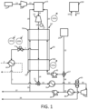
- fuel passes in line 13 from a fuel source 12, optionally being compressed in a fuel compressor 14, to be combusted in combustor 15.
- Oxidant pass through line 22 from oxidant source 25, which may, for example, and air separation unit, oxygen membrane, or other oxidant source.
- the oxidant may be passed directly to the combustor 15 but, as illustrated, the oxidant can be mixed with recycled CO 2 in mixer/union 27 before being compressed in pump 40 and passed in line 29 through the heat exchanger 50 on route to the combustor 15.
- the turbine exhaust stream in line 18 is passed through the heat exchanger 50, and a portion of the turbine exhaust stream exits the heat exchanger 50 in line 1 at an intermediate temperature.
- the heat exchanger 50 is shown as two separate heat exchange sections 50a and 50b; however, the dashed lines illustrate that the separate heat exchange sections may be connected as a single HEU operating with a plurality of sections (e.g., 2 or more, 3 or more, or even more portions) at different conditions.
- bypass heat exchanger 60 can use the bypass stream in line 1 as a heat source to provide thermal energy to any process outside of the illustrated power cycle. It should be noted that bypass heat exchanger 60 may simply be a dedicated section of the heat exchanger network 50 (e.g., bypass heat exchanger 60 may be integral to heat exchanger 50 and operated so that only the stream in line 1 passes therethrough for heat removal).
- valve 5 As intermediate temperatures within heat exchanger 50 approach maximum design limits, the controller providing control over valve 5 will send a signal to valve 5 to open. This will encourage the flow of the stream in line 1 through the bypass heat exchanger 60 before passing on to heat exchanger 70. If operating conditions (e.g., power demand) are such that the intermediate temperatures in heat exchanger 50 are below design limits, then valve 5 may remain closed (or be closed if previously opened) in order to bias the flow through the remainder of heat exchanger 50 (e.g., heat exchange section 50b). This has the benefit of improving the thermal recovery of the power cycle. Any number of bypasses may be integrated in parallel into heat exchanger 50 as a means of providing more finite temperature control at various parts of the exchanger train.
- control of the bypass line 1 may be effected based upon power output from the turbine 10 and the generator 17.
- a signal 101b indicating a change in power demand effective to cause an operational change of the turbine 10 altering power generation from the generator 17 of the power production plant can be received by the controller 100.
- the controller 100 can provide an output 102b that causes more or less fluid to pass through line 1.
- the power production cycle otherwise may continue in that the turbine exhaust in line 18 can merge with the bypass stream in line 1, such as in a mixer/union 21, prior to passage in line 19 to heat exchanger 70, wherein the exhaust stream is cooled to near ambient temperature.
- the exhaust stream then passes through 34 to separator 35 wherein a substantially pure stream of CO 2 is provided in line 36.
- the stream of CO 2 is then compressed in compressor 30, optionally cooled in heat exchanger 80, then pumped in pump 20 to the desired pressure range to be recycled back to the combustor 15 through line 39.
- a portion of the CO 2 stream in line 39 can be branched in line 38 and passed to the mixer/union 27, as referenced above, for admixture with the oxidant.
- a portion of the CO 2 in line 39 may be separated and passed through line 37 for export or other end use, such as EOR. Water from separator 35 can be passed out of the system through drain line 33.
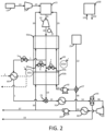
- FIG. 2 thus illustrates an embodiment, wherein elements already described in relation to FIG. 1 are substantially unchanged.
- the power production system can be configured to provide for recirculation of at least a portion of one or both of the flows passing through the heat exchanger 50 from pump 20 and pump 40.
- valve 6 can be utilized for recirculation of at least a portion of recycle CO 2 stream passing through the heat exchanger 50 in line 39 so that said portion of the recycle CO 2 stream is passed to the turbine exhaust stream in line 18.
- valve 7 can be utilized for recirculation of at least a portion of the oxidant stream passing through the heat exchanger 50 in line 29 so that said portion of the oxidant stream is passed to the turbine exhaust stream in line 18.
- Adjusting a heat profile of the HEU thus can include one or both of the following: causing a portion of a recycle stream being heated in the HEU to be passed to an exhaust stream being cooled in the HEU such that said adjusting is effective to increase the mass flow of the exhaust stream passing through a section of the HEU; and causing a portion of an oxidant stream being heated in the HEU to be passed to an exhaust stream being cooled in the HEU such that said adjusting is effective to increase the mass flow of the exhaust stream passing through a section of the HEU. More particularly, as the desired output of turbine 10 is increased, the discharge flow rates of pump 20 and/or pump 40 to the combustor 15 can be controlled to likewise increase as needed.
- valve 6 in line 39a or valve 7 in line 29a in the heat exchanger 50 will begin to close. This will not only deliver more mass flow to the combustor 15 (and ultimately to the turbine 10), but it will also increase the amount of thermal energy provided by the heat exchanger 50 to the combustor 15. Otherwise, when a power output of the turbine 15 is reduced, valve 6 and valve 7 can be opened as needed. This artificially increases the flow rate through the lower half of the heat exchanger 50 (e.g., through heat exchange section 50b) and quenches the turbine exhaust temperature to further help manage the heat exchanger temperature profile.
- the control function therefore can comprise causing one or both of a portion of the recycle stream and a portion of the oxidant stream to be passed to the exhaust stream responsive to one or both of the following inputs: a signal indicating a change in power demand effective to cause an operational change of a turbine altering power generation from the power production plant (see signal 101b in FIG. 1 ); and a signal indicating that a temperature within the HEU is within a defined threshold of a maximum operating temperature of the HEU (see signal 101a in FIG. 1 ).
- Output signals 102c and 102d may thus be generated for controlling fluid passage through valve 6 and valve 7, respectively.
- signals 101a and 101b are shown as example embodiments, it is understood that similar signals may be received from a variety of components of the present systems.
- input signals may be received by the controller from any of the pump 20, the pump 40, the compressor 30, the compressor 31, an IGV 32, the separator 35, the compressor 14, and any of the lines described herein.
- signals may relate information directed to a pressure at a certain point in the system, a flow rate at a certain point in the system, a temperature at a certain point in the system, a molar concentration of a compound at a certain point in the system, or any similar parameter that may be useful for implementing a control function as otherwise described herein.
- suitable input signals may include any one or more of the following: a power demand signal; a gasifier output signal (e.g., indicating that the syngas flow exceeds a defined threshold amount); a hydrogen demand signal (e.g., indicating that the hydrogen flow exceeds a defined threshold amount); a syngas chemistry signal from the gasifier (e.g., which can be indicative that the estimated or actual mole fraction of one or more components of the produced syngas exceeds a defined threshold); a signal defining a syngas chemistry for the syngas stream being sent to the power cycle (the mixed stream from the bypass and the reduced hydrogen syngas stream); a feedstock modification signal; an ASU operation signal; a nitrogen availability signal; a mixed fuel Wobbe index signal; and the like.
- output signals may be directed for control of any one or more of the above-exemplified components of the system in order to implement a control function as otherwise described herein.
- the heat exchanger bypass line 1 may be used to limit the rate of temperature change in the heat exchanger 50 in conjunction with the maximum flow rates of pump 20 and/or pump 40 being provided near instantaneously through the heat exchanger 50 with minimal use of the recirculation lines (29a, 39a).
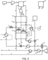
- a power cycle can be operated to utilize one or more recompression systems, and such systems likewise can be controlled so as to manage the flow through the recompression cycle to achieve intermediate temperature management in the heat exchanger 50.
- Recompression systems not only pressurize the recycle fluid but also provide low-grade heat to the power cycle's main recuperative heat exchanger (e.g., heat exchanger 50) as a means of recycle temperature optimization.
- FIG. 3 depicts a directly fired sCO 2 cycle with a recompression system originating from within the heat exchanger 50.
- compressor 31 in recompression line 3 by increasing its suction temperature (and thereby also its outlet temperature) as a constant outlet pressure is maintained. Energy consumption of compressor 31 will also be expected to increase in such embodiments. In some embodiments, this trend may be effectively reversed by actively reducing the flow rate through compressor 31 while maintaining a substantially constant outlet temperature for the exhaust stream in line 3.
- a controller for compressor 31 can actively monitor one or more check points on line 3 to ensure that the stream in line 3 does not exceed an optimized desired temperature by providing feedback to location of the inlet guide vane (IGV) 32 of the compressor 31.
- IGV inlet guide vane
- control function can comprise closing an inlet guide vane (IGV) 32 of the recirculation compressor 31 responsive to a signal indicating that a temperature within the HEU is within a defined threshold of a maximum operating temperature of the HEU (see, for example, signal 101a in FIG. 1 ).
- IGV inlet guide vane
- FIG. 3 Such output signal is shown in FIG. 3 as signal 102e.
- the IGVs are used to limit power consumption while maintaining a safe margin to surge. IGVs may be used to control discharge pressure through various controllers. However, in certain situations, the IGVs may be placed into manual control and forced open in order to increase the flow in the recycle lines. In such a case, the inventory of the system will increase.
- the IGVs of the compressor 31 can be closed in order to decrease exhaust flow through the unit.
- the reduction in flow and subsequent low-grade heat addition to the heat exchanger 50 can create a cascading effect where average heat exchanger temperature will reduce.
- the feedback of reducing flow and reducing suction temperature at the compressor 31 will converge upon a mode of operation where the requirement at the check point is satisfied. This will also lead to the lowest energy consumption at compressor 31 required to maximize the recycle temperature level that may be obtained with the heat exchanger 50.
- the IGVs of compressor 30 may need to open to allow it to pressurize an increased amount of flow.
- the suction temperature of compressor 31 may fall and so may the temperature check point on line 3. This would actually force the IGVs of compressor 31 to open to generate more heat.
- the IGVs of compressor 30 would need to close to account for increased flow at compressor 31.
- IGVs may be substituted with recirculation lines and coolers.
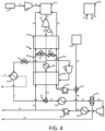
- a further heat source can be provided at an intermediate temperature in the heat exchanger 50.
- the heater 90 may operate by providing heat directly or indirectly.
- the source of heat can also vary such as it may come from electricity, solar, nuclear, or fuel combustion resources.
- the heater 90 may also be located on any of the streams within the heat exchanger network 50.
- heater 90 is an oxy-fired duct burner on the exhaust flow of turbine 10. Combusted fuel emissions freely mix with the turbine exhaust flow and contribute to a temperature rise. This addition of thermal energy may serve several purposes.
- heater 90 is located downstream of the bypass line 1, the recirculation lines 29a and 39a, and the recompression line 3, which are all described above.
- the plant may be essentially preheated while the balance of the cycle around turbine 10 operates in a substantially closed-loop manner.
- the bypass lines associated with valve 6 and/or valve 7 may divert part or all of their source flows.
- the design flow rates can be configured to accommodate over-speed protection of the turbine 10 in the event of a trip scenario.
- the heater 90 may be used to provide additional thermal energy for heat exchanger 60 to the extent that the temperature profile of the heat exchanger network 50 is minimally affected.
- the various temperature control schemes described herein can be used independently or in any combination with one or more of the further control schemes described herein. Should multiple temperature control schemes be used simultaneously, their activities can be prioritized in a manner as described herein.
- the use of heater 90 can negate this effect and allow heat recovery at heat exchanger 60 to merely share balance of plant resources with the power cycle.
- the outlet temperature of pump 20 can be controlled to its optimal value.
- the flow rate through the recompression system e.g., line 3 and compressor 31
- the flow rate through the recompression system can be minimized or maximized to the extent that the temperature at check point on line 3 approaches its optimal desired value.
- the power production plant can include a heater 90 that is configured for operation independent of the HEU 50.
- independent operation can mean simply that the heat provided by the heater 90 is from a source other than any heated stream that is used to provide heat exchange in the HEU 50.
- the heater 90 can be configured for addition of heat to the turbine exhaust stream 18 at a point that is positioned between the first HEU end 50' and the second HEU end 50".
- the heater 90 for example, can be a combustion heater. Further configurations and components can be identified based upon the further components that are illustrated in relation to FIG. 1 through FIG. 5 as already discussed above.
- the CO 2 may be at an elevated temperature prior to use in the downstream process, it may be desirable to heat it against the main recuperative heat exchanger train in the power production cycle counter-currently to the turbine exhaust flow path.
- the flow rate through the hot gas compressor can be increased by opening the inlet guide vanes ("IGVs") on the unit. This will serve the purpose of providing an increase in low-grade heat to the heat exchanger train. It will also reduce the total flow rate of CO 2 through the main CO 2 compressor. This will force the IGVs on this unit to close in order to accommodate the new conditions.
- IGVs inlet guide vanes
- the total gross power output at the turbine will not change given that the inlet conditions will remain the same as beforehand. There also won't be a change in fuel input to the facility given that the recycle CO 2 temperature has been maintained. Rather, the net power output of the plant will reduce given that the hot gas compressor operates less efficiently as a pressurization device than the main CO 2 compressor.
- the basic effect is that fuel has been converted to electricity to then be exported as thermal energy in the discharged CO 2 stream. All combustion and pressurization activities are inherently managed by the equipment and controls capabilities of the power cycle.
- the quality and quantity of heat to the downstream process may be varied by the amount of export CO 2 heated by the recuperative heat exchanger train as well as the total flow rate of CO 2 processed by the hot gas compressor.
- the presently disclosed systems and methods allow the hot gas compressor in the power production cycle to provide low grade heat for the optimization of the recuperative heat exchanger while also serving as a heat source for external industrial processes utilizing the cycle's export CO 2 as a feedstock and/or heat transfer fluid.
- the hot gas compressor is managed in such a way that the inlet conditions to the turbine (and therefore gross performance) do not change while heat is being provided to a downstream industrial process. Therefore, thermal cycling of the turbine does not occur.
- the net power output of the power production cycle is reduced given that the heat generated for the external industrial process increases the parasitic load of the hot gas compressor (i.e., effectively converting electricity back into thermal energy).
- urea synthesis may be particularly combined with the power cycle, and this can require an ammonia source.
- the necessary ammonia (NH 3 ) can be either a co-product of the underlying power production cycle, or it can be bought as a commodity (e.g., from outside ammonia plants).
- a power production cycle according to the present disclosure exporting CO 2 for urea synthesis can be carried out to provide a method for co-production of power and urea.
- CO 2 can be formed in the combustion process as otherwise described herein (e.g., taken as a product from line 37, taken at an increased temperature from some point in line 39, or taken at a lower pressure upstream from the pump 20).
- high grade heat of combustion can be recuperated from the combustor exhaust or a turbine exhaust stream (e.g., at a point from the heat exchanger 50) by counter-current heating of cold, recycle CO 2 to the required combustion inlet temperature.
- This can be specifically the pressurized stream exiting the pump 20.
- the IGV 32 of the compressor e.g., compressor 31
- the low grade heat e.g., at approximately a temperature of 150 to 300 °C
- the flow rate of CO 2 at the compressor inlet can be dictated by the amount of extra low grade heat required for downstream Urea synthesis.
- the IGV of the main compressor 30 can be closed to adjust CO 2 entering it correspondently.
- Total CO 2 at the primary heat exchanger 50 outlet can be sent to the separator 35 for liquid water removal, and SOx/NOx (if any) removal.
- CO 2 can be compressed and pumped to the required pressure (e.g., in compressor 30 and pump 20), and a portion of the CO 2 can be separated from the main CO 2 stream at a pressure of about 140-175 bar.
- the separated CO 2 can be directed into the primary heat exchanger 50 to be heated to about 190 °C, then this portion of CO 2 at about 140-175 bar and about 190 °C can be sent to the downstream Urea production unit.
- the power cycle can be utilized in relation to carbon capture, utilization, and storage in a saline aquifer.
- pressurized CO 2 e.g., from line 37
- the stream Prior to being injected below grade, the stream can be preheated to a temperature above the reservoir's water dew point through the systems and methods described herein utilizing a power production cycle.
- a portion of the liquid content is vaporized.
- a mixture of steam (desalinated water) and a portion of the injected CO 2 flow through an adjacent relief well allowing for the harvest of water and reuse of CO 2 at the surface.
- the reservoir has been depressurized allowing for further CO 2 storage.
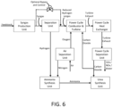
- the system can comprise: a power production unit including at least a combustor, a turbine, a heat exchanger, and a separation unit, the power production unit being configured to receive a fuel stream and an oxidant and output power and substantially pure carbon dioxide; a syngas production unit configured to receive a feedstock and provide a syngas product, at least a portion of which is effective for use as at least a portion of the fuel stream in the power production unit; an air separation unit configured to provide oxygen for use as the oxidant in the power production unit and configured to provide nitrogen; and one or both of an ammonia synthesis unit and a urea synthesis unit.
- the ammonia synthesis unit specifically can be present. In such cases, it can be desirable for the ammonia synthesis unit to be configured to receive nitrogen from the air separation unit, configured to receive hydrogen from a hydrogen source, and configured to output ammonia.
- the hydrogen source can be a hydrogen separation unit configured to receive at least a portion of the syngas product from the syngas production unit and provide a stream of hydrogen and a stream of hydrogen-reduced syngas that is effective for use as at least a portion of the fuel stream in the power production unit.
- the systems and methods can incorporate the use of an optional bypass and control which can allow a portion of the syngas to bypass the hydrogen separation and proceed directly to the power cycle. This allows for more freedom of operation and a partial de-coupling of the gasifier, the power cycle, and the hydrogen production.
- the bypass line may be controlled based upon a variety of input signals that may be received by the controller (e.g., controller 100 in FIGs. 1-5 ).
- suitable input signals may include any one or more of the following: a power demand signal; a gasifier output signal (e.g., indicating that the syngas flow exceeds a defined threshold amount); a hydrogen demand signal (e.g., indicating that the hydrogen flow exceeds a defined threshold amount); a syngas chemistry signal from the gasifier (e.g., which can be indicative that the estimated or actual mole fraction of one or more components of the produced syngas exceeds a defined threshold); a signal defining a syngas chemistry for the syngas stream being sent to the power cycle (the mixed stream from the bypass and the reduced hydrogen syngas stream); a feedstock modification signal; an ASU operation signal; a nitrogen availability signal; a mixed fuel Wobbe index signal; and the like.
- a power demand signal e.g., indicating that the syngas flow exceeds a defined threshold amount
- a hydrogen demand signal e.g., indicating that the hydrogen flow exceeds a defined threshold amount
- a syngas chemistry signal from the gasifier
Landscapes
- Engineering & Computer Science (AREA)
- Chemical & Material Sciences (AREA)
- Combustion & Propulsion (AREA)
- Chemical Kinetics & Catalysis (AREA)
- Mechanical Engineering (AREA)
- General Engineering & Computer Science (AREA)
- Environmental & Geological Engineering (AREA)
- Biomedical Technology (AREA)
- Health & Medical Sciences (AREA)
- Analytical Chemistry (AREA)
- General Chemical & Material Sciences (AREA)
- Oil, Petroleum & Natural Gas (AREA)
- Life Sciences & Earth Sciences (AREA)
- Sustainable Development (AREA)
- Engine Equipment That Uses Special Cycles (AREA)
- Feedback Control In General (AREA)
- Supply And Distribution Of Alternating Current (AREA)
Description
- The present disclosure relates to control systems and methods, and more particularly to control systems and methods that can be integrated with power production systems and methods. The control systems and methods can be implemented particularly for management of thermal flows into and out of the power production system.
- There are many known systems and methods for the combustion of fossil fuels to produce electrical power. Documents
US2012/036860 A1 andUS2002/043064 A1 disclose such systems and methods. - Although alternative power production means are constantly being pursued, cost factors and availability of fossil fuels, especially coals and natural gas (as well as waste hydrocarbons, such as residual oil products), drive a continued need for systems configured to combust such fuels. Accordingly, there is a growing need for systems and methods that allow for high efficiency power production with complete carbon capture.
- The ability to provide power production from the burning of fossil fuels with complete carbon capture provides the potential for large volume production of carbon dioxide as a valuable commodity. The compound is used, for example, in the metals industry (e.g., to enhance hardness in casting molds), in manufacturing and construction (e.g., as a shield gas in MIG/MAG welding), in chemical manufacturing (e.g., as a raw material in methanol and urea production), in petroleum field management (e.g., for enhanced oil production techniques), and in the food and beverage industries (e.g., for carbonation, for use as a refrigerant, for de-caffeinating coffee, for separation and purification of volatile flavor and fragrance concentrates, and for cold sterilization in admixture with ethylene oxide), to name a few. Depending upon the actual use, carbon dioxide input to an industrial use often must be pressurized and/or heated beyond ambient conditions.
- Provision of clean CO2 for uses such as noted above (as well as other uses) typically includes separation of the CO2 from an industrial gas mixture, which mixture often contains further compounds, such as CO, H2, sulfur, and the like. This, of course, requires a series of purification processes. The purification requirements as well as the need for providing the CO2 at the desired pressure and/or temperature can entail procuring dedicated compression, cleanup, and heating equipment that leads to high capital costs and large energy consumptions.
- In addition to the foregoing, power production processes are typically configured for utilization and production of significant amounts of thermal energy. This thermal energy may be utilized directly in power production or may be available for further uses. Thus, there is a need for means for controlling power production processes such that various product flows, such as carbon dioxide and modes of thermal transfer, may be efficiently obtained and/or exported for a further use.
- A method according to the invention is described in
claim 1 and a power production plant according to the invention is described inclaim 10. The control systems particularly can provide control over one or more of pressure, temperature, flow rate, and stream composition of one or more flow streams in a power production system. The control systems can provide for optimum efficiency of the power production system. The control systems further can provide control over aspects of the power production system, such as start-up of the system, shutdown of the system, change of input stream(s) in the system, change of output stream(s) in the system, handling of operating emergencies related to the system, and any like considerations related to operation of a power production system. In some embodiments, the control systems can be particularly adapted to or configured to provide for management of thermal flows into and out of the power production systems and methods. For example, thermal flows may be embodied in a heat transfer fluid and/or by passage of a dedicated stream in the power production system through a heat exchanger against a dedicated stream in a different system. - The present disclosure more particularly can relate to export of CO2 from a power production cycle such that the CO2 can be utilized in a variety of beneficial end uses without the need for compression and/or heating of the CO2 at the actual point of use.
U.S. Patent No. 8,596,075 to Allam et al describes a high efficiency power production cycle wherein oxyfuel combustion is carried out utilizing a recycle CO2 stream wherein at least a portion of the CO2 can be captured as a relatively pure stream. Because of the nature of the cycle wherein combustion gases and recycle CO2 can be provided at a variety of pressures and temperatures, such systems and methods can be configured according to the present disclosure to withdrawn substantially pure CO2 across a beneficially wide pressure and/or temperature range for export. - In one or more embodiments, the present disclosure thus provides to systems and methods whereby CO2 arising from a power production cycle utilizing CO2 as a working fluid can be taken as an end product and fed directly into a further downstream use of the material. For example, the systems and methods of the present disclosure can allow for the export of CO2 as a chemical feedstock and/or heat transfer fluid at various temperatures and pressures for use in downstream endothermic industrial processes.
- In some embodiments, the presently disclosed systems and methods are beneficial in that low-grade heat can be provided to an external process. This may be accomplished in an example embodiment by using combustion-derived CO2 effectively as a heat carrier. Moreover, the present disclosure provides for management of plant turndown (i.e. turbine stability and operability) through the export of said low-grade heat along with changes to the flow rate through the hot gas compressor ("HGC") of the power production system from which the CO2 is derived. As such, by relying upon the power production cycle utilizing a CO2 working fluid can, it is possible to partially or completely eliminate the need for combustion to be carried out separate from the power production cycle itself. As such, the maximum temperature can be limited by the total heat quality and quantity that can be taken from the recuperative heat exchanger train utilized in the power production cycle before the hot gas compressor can no longer supplement the losses (i.e. maintain heat exchanger profile). In this manner, the systems and methods of the present disclosure can provide distinct advantages over other possible industrial sources of CO2, such as systems wherein CO2 compression heat is recovered in order to help generate steam that is used to strip CO2 from recovery columns. In such less desirable alternatives, the heat recovery process is an add-on independent of direct power generation activities and thus cannot provide many of the advantages of the presently disclosed systems and methods. As such, known systems and methods do not include using combustion derived CO2 taken from a supercritical CO2 power production cycle, and likewise do not contemplate supplying external thermal energy for chemical processes by using CO2 as a transportable heat sink.
- In one or more examples, the present disclosure can provide a method for providing a CO2 stream for an end use thereof. For example, such method can comprise: combusting a fuel to form a combustion stream comprising CO2; generating power; removing one or more contaminants from the combustion stream to provide a substantially pure stream of CO2; and exporting the substantially pure stream of CO2 at one or both of a temperature and pressure that is greater than ambient. In particular, exported CO2 can be at a pressure of about 2 bar or greater, about 5 bar or greater, about 10 bar or greater, about 25 bar or greater, about 50 bar or greater, or about 100 bar or greater (said export pressure having an upper limit in line with pressure limits inherent to the equipment required to compress the CO2 and the equipment used to transport the CO2). In some examples, the pressure can be about 2 bar to about 500 bar, about 10 bar to about 490 bar, about 25 bar to about 480 bar, about 50 bar to about 475 bar, about 75 bar to about 450 bar, or about 100 bar to about 400 bar. Exported CO2 can be at a temperature of about 35 °C or greater, about 40 °C or greater, about 50 °C or greater, about 75 °C or greater, or about 100 °C or greater (said export temperature having an upper limit in line with temperature limits inherent to the equipment required handling of the CO2). In some examples, the temperature can be about 35 °C to about 500 °C, about 40 °C to about 450 °C, about 50 °C to about 400 °C, or about 60 °C to about 350 °C.
- In one or more embodiments, the present disclosure can relate to a control system suitable for use in a power production plant. For example, the power production plant can be a plant burning a fuel in substantially pure oxygen in a combustor at a pressure of about 12 MPa or greater with an additional circulating CO2 stream to produce a combined stream of combustion products and circulating CO2.
- The combined stream can be passed through a power producing turbine with a discharge pressure of at least 10 bar. The turbine exhaust can be cooled in an economizer heat exchange to preheat the circulating CO2 stream. The turbine exhaust can be further cooled to near ambient temperature, and condensed water can be removed. The CO2 gas stream can be compressed to be at or near the turbine inlet pressure using a gas compressor followed by a dense CO2 pump to form the circulating CO2 stream. Net CO2 produced in the combustor can be removed at any pressure between the turbine inlet and outlet pressures. Heat from an external source can be introduced to preheat part of the circulating CO2 stream to a temperature in the range 200°C to 400°C in order to reduce the temperature difference between the turbine exhaust and the circulating CO2 stream leaving the economizer heat exchanger to about 50°C or less. The fuel flow rate can be controlled to provide the required power output from the turbine. The turbine outlet temperature can be controlled by the speed of the CO2 pump. The CO2 compressor discharge pressure can be controlled by recycling compressed CO2 flow to the compressor inlet. The flow rate of net CO2 produced from fuel gas combustion and removed from the system can be used to control the CO2 compressor inlet pressure. The difference between the temperature of the turbine exhaust entering the economizer heat exchanger and the temperature of the circulating CO2 stream leaving the economizer heat exchange can be controlled to be at or below 50°C by controlling the flow rate of a portion of the circulating CO2 stream which is heated by an added heat source. The flow rate of net liquid water and fuel derived impurities removed from the system can be controlled by the level in the liquid water separator. The oxygen flow rate can be controlled to maintain a ratio of oxygen to fuel gas flow rate which can result in a defined excess oxygen in the turbine inlet flow to ensure complete fuel gas combustion and oxidation of components in the fuel gas. The oxygen stream at CO2 compressor inlet pressure can be mixed with a quantity of CO2 from the CO2 compressor inlet to produce an oxidant stream with an oxygen composition of about 15% to about 40% (molar), which can lower the adiabatic flame temperature in the combustor. The oxidant flow required to produce the required oxygen to fuel gas ratio can be controlled by the speed of the oxidant pump. The discharge pressure of the oxidant compressor can be controlled by recycling compressed oxidant flow to the compressor inlet. The inlet pressure of the oxidant compressor can be controlled by the flow rate of diluent CO2 mixed with the oxygen which forms the oxidant stream. The ratio of oxygen to CO2 in the oxidant stream can be controlled by the flow of oxygen. The oxygen can be delivered to the power system at a pressure at least as high as the turbine inlet pressure and where an oxidant stream with an oxygen composition in the range of about 15% to about 40% (molar) can be desired. The oxygen to fuel gas ratio can be controlled by the oxygen flow. The oxygen to CO2 ratio in the oxidant flow can be controlled by the flow of diluent CO2 taken from CO2 compressor discharge.
- In one or more examples, the present disclosure can provide power production systems that include an integrated control system, which can be configured for automated control of at least one component of the power production system. In particular, the control system can include at least one controller unit configured to receive an input related to a measured parameter of the power production system and configured to provide an output to the at least one component of the power production system subject to the automated control. The integrated control system can include a power controller configured to receive an input related to power produced by one or more power producing components of the power production system. The power controller can be configured to meet one or both of the following requirements: provide an output to a heater component of the power production system to increase or decrease heat production by the heater component; provide an output to a fuel valve to allow more fuel or less fuel into the power production system. The integrated control system can include a fuel/oxidant ratio controller configured to receive one or both of an input related to fuel flow rate and an input related to oxidant flow rate. The fuel/oxidant ratio controller can be configured to meet one or both of the following requirements: provide an output to a fuel valve to allow more fuel or less fuel into the power production system; provide an output to an oxidant valve to allow more oxidant or less oxidant into the power production system. The integrated control system can include a pump controller configured to receive an input related to temperature of an exhaust stream of a turbine in the power production system and to provide an output to a pump upstream from the turbine to increase or decrease flow rate of a stream exiting the pump. The integrated control system can include a pump suction pressure controller configured to receive an input related to suction pressure on a fluid upstream from a pump in the power production system and to provide an output to a spillback valve that is positioned upstream from the pump. The pump suction pressure controller is configured to meet one or both of the following requirements: cause more of the fluid or less of the fluid to spill back to a point that is further upstream from the spillback valve; cause more of the fluid or less of the fluid to be removed from the power production system upstream from the pump. The integrated control system can include a pressure regulation controller configured to receive an input related to pressure of an exhaust stream of a turbine in the power production system and to provide an output to a fluid outlet valve and allow fluid out of the exhaust stream and optionally to provide an output to a fluid inlet valve and allow fluid into the exhaust stream. The integrated control system can include a water separator controller configured to receive an input related to the amount of water in a separator of the power production system and to provide and output to a water removal valve to allow or disallow removal of water from the separator and maintain the amount of the water in the separator within a defined value. The integrated control system can include an oxidant pump controller configured to receive an input related to one or both of a mass flow of a fuel and a mass flow of an oxidant in the power production system and calculate a mass flow ratio of the fuel and the oxidant. The oxidant pump controller can be configured to provide an output to the oxidant pump to change the power of the pump so as to affect the mass flow ratio of the fuel and the oxidant in the power production system. The integrated control system can include an oxidant pressure controller configured to receive an input related to the pressure of an oxidant stream downstream from an oxidant compressor and to provide an output to an oxidant bypass valve to cause more oxidant or less oxidant to bypass the compressor. The integrated control system can include an oxidant pressure controller configured to receive an input related to the pressure of an oxidant stream upstream from an oxidant compressor and to provide an output to a recycle fluid valve to cause more recycle fluid or less recycle fluid from the power production system to be added to the oxidant stream upstream from the oxidant compressor. In particular, the recycle fluid can be a substantially pure CO2 stream. The integrated control system can include a dilution controller configured to receive an input related to one or both of the mass flow of an oxidant and the mass flow of an oxidant diluent stream and to calculate a mass flow ratio of the oxidant and the oxidant diluent. The dilution controller can be configured to provide an output to an oxidant entry valve to allow more oxidant or less oxidant to enter the power production system so that the mass flow ratio of the oxidant to the oxidant diluent is within a defined range. The integrated control system can include a compressor suction pressure controller configured to receive an input related to suction pressure of a fluid upstream from a compressor in the power production system and to provide an output to a spillback valve that is positioned downstream from the compressor and that causes more of the fluid or less fluid to spill back to a point that is upstream from the compressor. The integrated control system can include a pump speed controller configured to receive an input related to suction pressure upstream from the pump and to provide an output to the pump to increase or decrease pump speed. The integrated control system can include a side flow heat controller configured to receive an input related to a calculated mass flow requirement for a side flow of a high pressure recycle stream in the power production system and to provide an output to a side flow valve to increase or decrease the amount of the high pressure recycle stream in the side flow.
- The power production system can comprise: a turbine; a compressor downstream from the turbine and in fluid connection with the turbine; a pump downstream from the compressor and in fluid connection with the compressor; and a heater positioned downstream from the pump and in fluid connection with the pump and positioned upstream from the turbine and in fluid connection with the turbine. Optionally, the power production system can include a recuperator heat exchanger.
- In one or more examples, the present disclosure can provide methods for automated control of a power production system. In particular, the method can comprise operating a power production system comprising a plurality of components that include: a turbine; a compressor downstream from the turbine and in fluid connection with the turbine; a pump downstream from the compressor and in fluid connection with the compressor; and a heater positioned downstream from the pump and in fluid connection with the pump and positioned upstream from the turbine and in fluid connection with the turbine. Further, operating the power production system can include using one or more controllers integrated with the power production system to receive an input related to a measured parameter of the power production system and provide an output that automatically controls at least one of the plurality of components of the power production system.
- In further examples, the methods can include one or more of the following steps, which can be combined in any number and order. The output can be based upon a pre-programmed, computerized control algorithm. The operating can include using a controller to receive an input related to power produced by the power production system and direct one or both of the following actions: provide an output to the heater to increase or decrease heat production by the heater; provide an output to a fuel valve of the power production system to allow more fuel or less fuel into the power production system. The operating can include using a controller to receive one or both of an input related to fuel flow rate and an input related to oxidant flow rate and to direct one or both of the following actions: provide an output to a fuel valve of the power production system to allow more fuel or less fuel into the power production system; provide an output to an oxidant valve of the power production system to allow more oxidant or less oxidant into the power production system. The method operating can include using a controller to receive an input related to temperature of an exhaust stream of the turbine and provide an output to the pump upstream from the turbine to increase or decrease flow rate of a stream exiting the pump. The operating can include using a controller to receive an input related to suction pressure on a fluid upstream from the pump and provide an output to a spillback valve that is positioned upstream from the pump. In particular, one or both of the following requirements can be met: the controller causes more of the fluid or less of the fluid to spill back to a point that is further upstream from the spillback valve; the controller causes more of the fluid or less of the fluid to be removed from the power production system upstream from the pump. The operating can include using a controller to receive an input related to pressure of an exhaust stream of the turbine and provide an output to a fluid outlet valve and allow fluid out of the exhaust stream and optionally provide an output to a fluid inlet valve and allow fluid into the exhaust stream. The operating can include using a controller to receive an input related to the amount of water in a separator included in the power production system and provide and output to a water removal valve to allow or disallow removal of water from the separator and maintain the amount of the water in the separator within a defined value. The operating can include using a controller to receive an input related to one or both of a mass flow of a fuel and a mass flow of an oxidant introduced to the power production system and calculate a mass flow ratio of the fuel and the oxidant. In particular, the controller can provide an output to an oxidant pump to change the power of the pump so as to affect the mass flow ratio of the fuel and the oxidant in the power production system. The operating can include using a controller to receive an input related to the pressure of an oxidant stream downstream from an oxidant compressor and provide an output to an oxidant bypass valve to cause more oxidant or less oxidant to bypass the compressor. The operating can include using a controller to receive an input related to the pressure of an oxidant stream upstream from an oxidant compressor and to provide an output to a recycle fluid valve to cause more recycle fluid or less recycle fluid to be added to the oxidant stream upstream from the oxidant compressor. In particular, the recycle fluid can be a substantially pure CO2 stream. The operating can include using a controller to receive an input related to one or both of the mass flow of an oxidant and the mass flow of an oxidant diluent stream and to calculate a mass flow ratio of the oxidant and the oxidant diluent. In particular, the controller can be configured to provide an output to an oxidant entry valve to allow more oxidant or less oxidant to enter the power production system so that the mass flow ratio of the oxidant to the oxidant diluent is within a defined range. The operating can include using a controller to receive an input related to suction pressure of a fluid upstream from the compressor and provide an output to a spillback valve that is positioned downstream from the compressor and that causes more of the fluid or less fluid to spill back to a point that is upstream from the compressor. The operating can include using a controller to receive an input related to suction pressure upstream from the pump and to provide an output to the pump to increase or decrease pump speed. The operating can include using a controller to receive an input related to a calculated mass flow requirement for a side flow of a high pressure recycle stream and provide an output to a side flow valve to increase or decrease the amount of the high pressure recycle stream in the side flow.
- In some examples, methods for control of a power production plant can comprise: adjusting a heat profile of a heat exchange unit (HEU) operating with a plurality of streams passing between a first HEU end having a first operational temperature and a second HEU end having a second, lower operational temperature; wherein said adjusting comprises implementing a control function that alters a mass flow of one or more of the plurality of streams passing between the first HEU end and the second HEU end by adding mass flow to or withdrawing mass flow from the one or more of the plurality of streams at an intermediate temperature range within the HEU at a point that is positioned between the first HEU end and the second HEU end. Such methods may be further defined in relation to one or more of the following statements, which can be combined in any number and order.
- The adjusting can comprise causing a portion of a heated stream passing through the HEU to bypass a section of the HEU through a bypass line such that said adjusting is effective to reduce the mass flow of the heated stream that passes through the section of the HEU that is bypassed.
- The heated stream passing through the HEU can be a heated turbine exhaust stream from a turbine, the heated turbine exhaust stream passing from the first HEU end to the second HEU end to provide a cooled turbine exhaust stream, and wherein the cooled turbine exhaust stream can be further processed through one or more of a separator, a compressor, and a pump.
- The control function can comprise causing the portion of the heated stream passing through the HEU to bypass the section of the HEU through the bypass line responsive to one or both of the following signals received by a controller: a signal indicating a change in power demand effective to cause an operational change of the turbine altering power generation from the power production plant; and a signal indicating that a temperature within the HEU is within a defined threshold of a maximum operating temperature of the HEU.
- The control function can comprise opening a valve positioned in the bypass line.
- The portion of the heated stream passing through the bypass line can be rejoined with the cooled turbine exhaust stream downstream from the second HEU end and upstream from one or more of the separator, the compressor, and the pump.
- The method further can comprise causing the portion of the heated stream passing through bypass line to be processed through a bypass heat exchanger effective to transfer heat from the portion of the heated stream in the bypass line to one or more further streams.
- The adjusting can comprise one or both of the following: causing a portion of a recycle stream being heated in the HEU to be passed to an exhaust stream being cooled in the HEU such that said adjusting is effective to increase the mass flow of the exhaust stream passing through a section of the HEU; and causing a portion of an oxidant stream being heated in the HEU to be passed to an exhaust stream being cooled in the HEU such that said adjusting is effective to increase the mass flow of the exhaust stream passing through a section of the HEU.
- The control function can comprise causing the respective portion of the recycle stream and the oxidant stream to be passed to the exhaust stream responsive to one or both of the following: a signal indicating a change in power demand effective to cause an operational change of a turbine altering power generation from the power production plant; a signal indicating that a temperature within the HEU is within a defined threshold of a maximum operating temperature of the HEU.
- The power production plant can include a recirculation compressor configured for withdrawing a portion of a heated turbine exhaust stream passing through the HEU, compressing the portion of the heated turbine exhaust stream that is withdrawn, and recombining the portion of the heated turbine exhaust stream that is compressed at a downstream section of the HEU.
- The control function can comprise closing an inlet guide vane (IGV) of the recirculation compressor responsive to a signal indicating that a temperature within the HEU is within a defined threshold of a maximum operating temperature of the HEU.
- The method further can comprise adding heat to one or more of the plurality of streams passing between the first HEU end and the second HEU end, wherein the heat is added at an intermediate temperature range within the HEU at a point that is positioned between the first HEU end and the second HEU end, and wherein the heat is added using a heater that is operated independent of the HEU.
- The heater can be a combustion heater.
- The heat can be added to a turbine exhaust stream passing through the HEU, and wherein an exhaust stream from the combustion heater is added directly to the turbine exhaust stream.
- In further examples, the present disclosure may particularly relate to power production plants. For example, a power production plant can comprise: a turbine; a power generator; a heat exchange unit (HEU); one or more compressors or pumps; and a control unit; wherein the HEU is configured for heat exchange between a plurality of streams passing between a first HEU end having a first operational temperature and a second HEU end having a second, lower operational temperature; wherein the HEU includes one or more components configured to add mass flow to or withdraw mass flow from one or more of the plurality of streams at a point that is positioned between the first HEU end and the second HEU end such that a portion of a fluid passing through the one or more of the plurality of streams is diverted from passage through a remaining section of the HEU; and wherein the control unit is configured to receive a signal defining an operating condition of the power production plant and, based thereon, output a signal effective to control the one or more components configured to add mass flow to or withdraw mass flow from the one or more of the plurality of streams. Such power plants may be further defined in relation to one or more of the following statements, which can be combined in any number and order.
- The HEU can be configured for heat exchange between at least a turbine exhaust stream exiting a turbine and one or both of a recycle stream and an oxidant stream.
- The one or more components configured to add mass flow to or withdraw mass flow from one or more of the plurality of streams can include a bypass line and a bypass valve configured to divert a portion of the turbine exhaust stream around a section of the HEU.
The power production plant further can comprise a bypass heat exchanger operational with the bypass line and configured to transfer heat from the portion of the turbine exhaust stream diverted therethrough to one or more further streams. - The one or more components configured to add mass flow to or withdraw mass flow from one or more of the plurality of streams include a recirculation line and a recirculation valve interposed between the turbine exhaust stream and the recycle stream.
- The one or more components configured to add mass flow to or withdraw mass flow from one or more of the plurality of streams include a recirculation line and a recirculation valve interposed between the turbine exhaust stream and the oxidant stream.
- The power production plant further can comprise a heater that is configured for operation independent of the HEU, the heater being configured for addition of heat to the turbine exhaust stream at a point that is positioned between the first HEU end and the second HEU end.
- The heater can be a combustion heater.
- In further examples, the present disclosure can provide systems for cogeneration of power and one or more end products. Such systems can comprise: a power production unit including at least a combustor, a turbine, a heat exchanger, and a separation unit, the power production unit being configured to receive a fuel stream and an oxidant and output power and substantially pure carbon dioxide; a syngas production unit configured to receive a feedstock and provide a syngas product, at least a portion of which is effective for use as at least a portion of the fuel stream in the power production unit; an air separation unit configured to provide oxygen for use as the oxidant in the power production unit and configured to provide nitrogen; and one or both of an ammonia synthesis unit and a urea synthesis unit. In further examples, such systems may be defined in relation to one or more of the following statements, which can be combined in any number and order.
- The ammonia synthesis unit can be present and can be configured to receive nitrogen from the air separation unit, configured to receive hydrogen from a hydrogen source, and configured to output ammonia.
- The hydrogen source can be a hydrogen separation unit configured to receive at least a portion of the syngas product from the syngas production unit and provide a stream of hydrogen and a stream of hydrogen-reduced syngas that is effective for use as at least a portion of the fuel stream in the power production unit.
- The urea synthesis unit can be present and can be configured to receive nitrogen from a nitrogen source, configured to receive carbon dioxide from the power production cycle, and configured to output a urea stream.
- The nitrogen source can be the ammonia synthesis unit.
-
-
FIG. 1 is a diagram of a power production system and method according to an example of the present disclosure. -
FIG. 2 is a diagram of a power production system and method according to an embodiment of the present invention. -
FIG. 3 is a diagram of a power production system and method according to a further embodiment of the present invention. -
FIG. 4 is a diagram of a power production system and method according to a further embodiment according to the invention. -
FIG. 5 is a diagram of a power production system and method according to yet another embodiment of the present invention. -
FIG. 6 is a flowchart showing a process whereby power can be produced in connection with formation of one or more products suitable for export according to examples not covered by the present invention. - In one or more embodiments, the present disclosure provides systems and methods for control of power production. The control systems and methods can be utilized in relation to a wide variety of power production systems. For example, the control systems and methods may be utilized in power production system and methods utilizing a turbine for expansion of a pressurized fluid, particularly wherein turbine outlet temperature is held substantially constant or within a narrowly defined temperature range (e.g., ±20°C, ±15°C, ±10°C, or ±5°C). In some examples, the present systems and methods may be defined in that the mechanism that controls turbine inlet pressure may be substantially decoupled from the turbine itself. In examples, this can be in the form of a compressor or pump downstream of a primary pressurization machine that can either be shafted to the turbine or not. In other examples, the turbine may be connected to a generator and a single independently driven pressurization device can work in consort with the working fluid. In such examples, the control point between the compressor and pump may be substantially eliminated as described herein.
- Examples of power production systems and methods wherein a control system as described herein can be implemented are disclosed in
U.S. Pat. No. 9,068,743 to Palmer et al. U.S. Pat. No. 9,062,608 to Allam et al. U.S. Pat. No. 8,986,002 to Palmer et al. ,U.S. Pat. No. 8,959,887 to Allam et al. ,U.S. Pat. No. 8,869,889 to Palmer et al. ,U.S. Pat. No. 8,776,532 to Allam et al. , andU.S. Pat. No. 8,596,075 to Allam et al. As a non-limiting example, a power production system with which a control system as presently described may be utilized can be configured for combusting a fuel with O2 in the presence of a CO2 circulating fluid in a combustor, preferably wherein the CO2 is introduced at a pressure of at least about 12 MPa and a temperature of at least about 400 °C, to provide a combustion product stream comprising CO2, preferably wherein the combustion product stream has a temperature of at least about 800 °C. Such power production system further can be characterized by one or more of the following, which may be combined in any number and/or order: - the combustion product stream can be expanded across a turbine with a discharge pressure of about 1 MPa or greater to generate power and provide a turbine discharge steam comprising CO2;
- the turbine discharge stream can be passed through a heat exchanger unit to provide a cooled discharge stream;
- the cooled turbine discharge stream can be processed to remove one or more secondary components other than CO2 to provide a purified discharge stream;
- the purified discharge stream can be compressed to provide a supercritical CO2 circulating fluid stream;
- the supercritical CO2 circulating fluid stream can be cooled to provide a high density CO2 circulating fluid (preferably wherein the density is at least about 200 kg/m3);
- the high density CO2 circulating fluid can be pumped to a pressure suitable for input to the combustor;
- the pressurized CO2 circulating fluid can be heated by passing through the heat exchanger unit using heat recuperated from the turbine discharge stream;
- all or a portion of the pressurized CO2 circulating fluid can be further heated with heat that is not withdrawn from the turbine discharge stream (preferably wherein the further heating is provided one or more of prior to, during, or after passing through the heat exchanger); and/or
- the heated pressurized CO2 circulating fluid can be recycled into the combustor (preferably wherein the temperature of the heated, pressurized CO2 circulating fluid entering the combustor is less than the temperature of the turbine discharge stream by no more than about 50°C).
- The presently disclosed control systems can be particularly useful in relation to power production methods such as exemplified above because of the need for providing precise control over multiple parameters in relation to multiple streams, such parameters needing precise control to provide desired performance and safety. For example, in one or more examples, the present control systems can be useful in relation to any one or more of the functions otherwise described herein. In some examples, a control system and method as described herein in particular may include any one or more elements and/or features as described in
U.S. Pat. No. 10,103,737 to Fetvedt et al. - In one or more examples, the presently disclosed systems and methods can relate to heat profile regulation such as in relation to the systems illustrated in
FIG. 1 through FIG. 5 . Such systems generally can include at least onecontrol unit 100 configured to receive one ormore control inputs 101 effective to signal to thecontrol unit 100 to execute one or more control functions implemented via one or more control outputs 102.Control inputs 101 may relate to a measurable property, such as temperature, pressure, flow rate, power output, and the like, and the presently described systems may include one or more sensors or other measurement components configured to provide the desired output. The control outputs 102 may be effective to cause a change in operation of the system, such as opening or closing one or more valves, changing a compression pressure or pump speed to modify a flow rate of one or more streams, or similar operational variables. To this end, useful control systems can be adapted to or configured to control power output and/or turbine exhaust temperature in various power cycle configurations. While maintaining a substantially constant turbine outlet temperature atheat exchanger 50 can reduce stress related to thermal cycling, it does not completely eliminate it. The present disclosure thus can provide additional control functions to address such shortcomings. For example, as power demand atturbine 10 is reduced, a corresponding reduction in output pressure and mass flow can occur atpump 20. This can lead to a change in the heat exchanger thermal profile. - In examples, the present disclosure can provide one or more control functions effective to maintain system efficiency regardless of fluctuating power demand on the system and, alternatively or additionally, to prevent the temperature within one or more sections of the heat exchange unit from exceeding a defined threshold temperature (which can be related to a maximum operating temperature). For instance, a primary recuperative heat exchanger that has been designed and optimized for conditions compatible with full power output at the turbine can increasingly over-perform as power demand decreases. This is because the heat exchanger surface area will have been specified for relatively larger mass flow rates at the turbine exhaust and high pressure working fluid (such as supercritical carbon dioxide) recycle streams. This likewise may apply to oxidant flow as well. The reduction in pressure at the high-pressure working fluid recycle side can also lead to a lower specific heat of the recycle fluid (oxidant flow too if included). These changes may cumulatively manifest as increasing average heat exchanger temperature. To at least partially address such concerns, in some examples, the
heat exchanger 50 may be configured as a plurality of heat exchangers in series, and the interface temperatures between the units can rise as power demand at the turbine decreases. Such swings in temperature can create thermal stress, but more importantly, they may also lead to failure modes. - In some examples it can be desirable to construct
heat exchanger 50 to be as cost-effective as possible. Such an approach can lead to the use of differing materials throughout the range of temperatures in theheat exchanger 50. While all materials preferably are rated to the maximum outlet pressure ofpump 20 at full turbine power output (minimal losses for best performance), it will be necessary to design the materials to different temperatures as a means of promoting lowest cost solutions (cheapest materials and lowest cumulative masses). Accordingly, it can be preferable for the plant controls to include one or more functions effective for influencing the intermediate temperatures ofheat exchanger 50 in order to prevent design limit excursions given changes in heat exchanger average temperature that may occur. This may be achieved in a variety of manners as discussed herein. More particularly, the control functions may be effective to prevent one or more sections of a heat exchange unit (HEU) from exceeding a maximum operating temperature. As such, one or more controls may be implement to output a signal indicating that a temperature within the HEU (or within one or more specific sections of an HEU) is within a defined threshold of a maximum operating temperature. Such threshold may be, for example less than 20% below, less than 10% below, or less than 5% below the maximum operating temperature as defined by the manufacturer. Specifically, the threshold for outputting a high temperature signal may be a range that is within 20% to 1%, within 15% to 1%, within 10% to 1%, within 20% to 2%, within 15% to 2%, within 15% to 5%, within 10% to 2%, or within 10% to 5% of the maximum operating temperature. - The present disclosure therefore can relate to methods for control of a power production plant. In particular,
Figures 1-5 illustrate schematic flow diagrams of a power production plant according to various examples and embodiments, and the present methods may be implemented to incorporate any combination of elements and/or functions described in relation to said figures and/or expressly illustrated in said figures. In some embodiments, a control method may comprise adjusting a heat profile of a heat exchange unit (HEU) 50 operating with a plurality of streams passing between a first HEU end 50' having a first operational temperature and asecond HEU end 50" having a second, lower operational temperature. More particularly, the step of adjusting may include implementing a control function that alters a mass flow or volume flow of one or more of the plurality of streams passing between the first HEU end 50' and thesecond HEU end 50" by adding fluid (e.g., mass flow or volume flow) to or withdrawing fluid from (e.g., mass flow or volume flow) the one or more of the plurality of streams. This addition or withdrawal of fluid to the one or more streams may be carried out at an intermediate temperature range within the HEU. This means that the addition or withdrawal specifically can be carried out at a point that is positioned between the first HEU end 50' and thesecond HEU end 50". In other words, this can occur upstream from the second HEU end and downstream from the first HEU end. This can be, for example, at approximately a midpoint of theHEU 50 or at a point that is within 5-45%, 10-40%, or 20-35% of the distance from the first HEU end or at a point that is within 5-45%, 10-40%, or 20-35% of the distance from the first HEU end. Thus, the addition or withdrawal of fluid may take place at a section of the HEU that is nearer the first end (i.e., the "hot" end) or at a section of the HEU that is nearer the second end (i.e., the "cold" end). Any of these positions may be referenced herein as an "intermediate" position in the HEU. In some examples, the HEU may be a single integrated unit. In other examples, the HEU may be combination of a plurality of HEU sections that are fluidly connected. Thus, an intermediate position in the HEU may be a position between two discrete HEU sections. - In one or more examples, as illustrated in
FIG. 1 , one or more turbine exhaust bypass lines may be utilized for protection of theheat exchanger 50. Generally, inFIG. 1 , fuel passes inline 13 from afuel source 12, optionally being compressed in afuel compressor 14, to be combusted incombustor 15. Oxidant pass throughline 22 fromoxidant source 25, which may, for example, and air separation unit, oxygen membrane, or other oxidant source. The oxidant may be passed directly to thecombustor 15 but, as illustrated, the oxidant can be mixed with recycled CO2 in mixer/union 27 before being compressed inpump 40 and passed inline 29 through theheat exchanger 50 on route to thecombustor 15. In the combustor, the fuel is combusted with the oxidant in the presence of recycled CO2 to form an exhaust stream inline 16 that is then expanded inturbine 10 to generate power (e.g., electricity) in agenerator 17. Turbine exhaust then leaves theturbine 10 inline 18. - To effect bypass as noted previously, the turbine exhaust stream in
line 18 is passed through theheat exchanger 50, and a portion of the turbine exhaust stream exits theheat exchanger 50 inline 1 at an intermediate temperature. As illustrated inFIG. 1 , theheat exchanger 50 is shown as two separateheat exchange sections Valve 5 can be opened by the controller as needed so that a portion of flow of the turbine exhaust stream may leave the HEU to later rejoin the main turbine exhaust flow at a point upstream ofheat exchanger 70 and/or upstream from theseparator 35, and/or upstream from thecompressor 30, and/or upstream from thepump 20. Thus, the heat profile of the HEU can be effectively adjusted by causing a portion of the turbine exhaust stream (i.e., a heated stream) to bypass a section of the HEU through a bypass line. Removing a portion of the turbine exhaust gas fromline 18 at an intermediate point fromheat exchanger 50 has the net effect of reducing the total thermal energy transferred below the temperature in the heat exchanger at which the turbine exhaust stream inline 1 is taken. This results in a reduced average temperature for the remaining portion of the heat exchanger (e.g., available heat inheat exchange section 50b) at the expense of increasing the rejected duty atheat exchanger 70. - If desired, the heat in the turbine exhaust stream removed through
bypass line 1 may also be used to heat fluids other than the recycled CO2 that is provided throughline 39 and the oxidant that is provided throughline 29 toheat exchanger 50. To this end,bypass heat exchanger 60 can use the bypass stream inline 1 as a heat source to provide thermal energy to any process outside of the illustrated power cycle. It should be noted thatbypass heat exchanger 60 may simply be a dedicated section of the heat exchanger network 50 (e.g.,bypass heat exchanger 60 may be integral toheat exchanger 50 and operated so that only the stream inline 1 passes therethrough for heat removal). - The control function implemented in this fashion thus can cause a portion of a heated stream passing through the HEU to bypass a section of the HEU through the
bypass line 1 response to one or more signals received by thecontroller 100. For example, the input signal received by thecontroller 100 can be a signal indicating that a temperature within the HEU is within a defined threshold of a maximum operating temperature of the HEU. For example, atemperature output 101 can be generated from one or more temperature sensors at one or more check points within the HEU. Temperature check points withinheat exchanger 50 can be configured to provide feedback to acontroller operating valve 5. As such, thecontroller 100 may output a signal 102a to the valve 4 or to a further component of the power production plant to case more or less fluid to pass through thebypass line 1 as appropriate for the given conditions. As intermediate temperatures withinheat exchanger 50 approach maximum design limits, the controller providing control overvalve 5 will send a signal tovalve 5 to open. This will encourage the flow of the stream inline 1 through thebypass heat exchanger 60 before passing on toheat exchanger 70. If operating conditions (e.g., power demand) are such that the intermediate temperatures inheat exchanger 50 are below design limits, thenvalve 5 may remain closed (or be closed if previously opened) in order to bias the flow through the remainder of heat exchanger 50 (e.g.,heat exchange section 50b). This has the benefit of improving the thermal recovery of the power cycle. Any number of bypasses may be integrated in parallel intoheat exchanger 50 as a means of providing more finite temperature control at various parts of the exchanger train. The controller forvalve 5 and/or any other temperature control valves may in fact operate in such a manner that the power cycle is operated sub-optimally whereby heat recovery within the power cycle is minimized. This scenario may occur when the use of carbon free thermal energy is of greater use atheat exchanger 60 than for the production of power atturbine 10. - In further embodiments, control of the
bypass line 1 may be effected based upon power output from theturbine 10 and thegenerator 17. For example, asignal 101b indicating a change in power demand effective to cause an operational change of theturbine 10 altering power generation from thegenerator 17 of the power production plant can be received by thecontroller 100. In response, thecontroller 100 can provide anoutput 102b that causes more or less fluid to pass throughline 1. - The power production cycle otherwise may continue in that the turbine exhaust in
line 18 can merge with the bypass stream inline 1, such as in a mixer/union 21, prior to passage inline 19 toheat exchanger 70, wherein the exhaust stream is cooled to near ambient temperature. The exhaust stream then passes through 34 toseparator 35 wherein a substantially pure stream of CO2 is provided inline 36. The stream of CO2 is then compressed incompressor 30, optionally cooled inheat exchanger 80, then pumped inpump 20 to the desired pressure range to be recycled back to thecombustor 15 throughline 39. Optionally, a portion of the CO2 stream inline 39 can be branched inline 38 and passed to the mixer/union 27, as referenced above, for admixture with the oxidant. Likewise, a portion of the CO2 inline 39 may be separated and passed throughline 37 for export or other end use, such as EOR. Water fromseparator 35 can be passed out of the system throughdrain line 33. - An additional means of heat exchanger temperature control may also incorporate one or more control functions in addition to the above mentioned bypass scheme.
FIG. 2 thus illustrates an embodiment, wherein elements already described in relation toFIG. 1 are substantially unchanged. InFIG. 2 , the power production system can be configured to provide for recirculation of at least a portion of one or both of the flows passing through theheat exchanger 50 frompump 20 andpump 40. For example,valve 6 can be utilized for recirculation of at least a portion of recycle CO2 stream passing through theheat exchanger 50 inline 39 so that said portion of the recycle CO2 stream is passed to the turbine exhaust stream inline 18. Likewise,valve 7 can be utilized for recirculation of at least a portion of the oxidant stream passing through theheat exchanger 50 inline 29 so that said portion of the oxidant stream is passed to the turbine exhaust stream inline 18. - Adjusting a heat profile of the HEU thus can include one or both of the following: causing a portion of a recycle stream being heated in the HEU to be passed to an exhaust stream being cooled in the HEU such that said adjusting is effective to increase the mass flow of the exhaust stream passing through a section of the HEU; and causing a portion of an oxidant stream being heated in the HEU to be passed to an exhaust stream being cooled in the HEU such that said adjusting is effective to increase the mass flow of the exhaust stream passing through a section of the HEU. More particularly, as the desired output of
turbine 10 is increased, the discharge flow rates ofpump 20 and/or pump 40 to thecombustor 15 can be controlled to likewise increase as needed. Should the pumps be operating as fixed speed units, the appropriate valve in the respective recirculation line (e.g.,valve 6 inline 39a orvalve 7 inline 29a) in theheat exchanger 50 will begin to close. This will not only deliver more mass flow to the combustor 15 (and ultimately to the turbine 10), but it will also increase the amount of thermal energy provided by theheat exchanger 50 to thecombustor 15. Otherwise, when a power output of theturbine 15 is reduced,valve 6 andvalve 7 can be opened as needed. This artificially increases the flow rate through the lower half of the heat exchanger 50 (e.g., throughheat exchange section 50b) and quenches the turbine exhaust temperature to further help manage the heat exchanger temperature profile. - The control function therefore can comprise causing one or both of a portion of the recycle stream and a portion of the oxidant stream to be passed to the exhaust stream responsive to one or both of the following inputs: a signal indicating a change in power demand effective to cause an operational change of a turbine altering power generation from the power production plant (see
signal 101b inFIG. 1 ); and a signal indicating that a temperature within the HEU is within a defined threshold of a maximum operating temperature of the HEU (seesignal 101a inFIG. 1 ). Output signals 102c and 102d may thus be generated for controlling fluid passage throughvalve 6 andvalve 7, respectively. Althoughsignals pump 20, thepump 40, thecompressor 30, thecompressor 31, anIGV 32, theseparator 35, thecompressor 14, and any of the lines described herein. As such, signals may relate information directed to a pressure at a certain point in the system, a flow rate at a certain point in the system, a temperature at a certain point in the system, a molar concentration of a compound at a certain point in the system, or any similar parameter that may be useful for implementing a control function as otherwise described herein. For example, suitable input signals may include any one or more of the following: a power demand signal; a gasifier output signal (e.g., indicating that the syngas flow exceeds a defined threshold amount); a hydrogen demand signal (e.g., indicating that the hydrogen flow exceeds a defined threshold amount); a syngas chemistry signal from the gasifier (e.g., which can be indicative that the estimated or actual mole fraction of one or more components of the produced syngas exceeds a defined threshold); a signal defining a syngas chemistry for the syngas stream being sent to the power cycle (the mixed stream from the bypass and the reduced hydrogen syngas stream); a feedstock modification signal; an ASU operation signal; a nitrogen availability signal; a mixed fuel Wobbe index signal; and the like. Likewise, output signals may be directed for control of any one or more of the above-exemplified components of the system in order to implement a control function as otherwise described herein. - In embodiments wherein it may be desirable to operate the
turbine 10 so as to have a maximum output (e.g., operating at full load), then the heatexchanger bypass line 1 may be used to limit the rate of temperature change in theheat exchanger 50 in conjunction with the maximum flow rates ofpump 20 and/or pump 40 being provided near instantaneously through theheat exchanger 50 with minimal use of the recirculation lines (29a, 39a). - In one or more embodiments, a power cycle can be operated to utilize one or more recompression systems, and such systems likewise can be controlled so as to manage the flow through the recompression cycle to achieve intermediate temperature management in the
heat exchanger 50. Recompression systems not only pressurize the recycle fluid but also provide low-grade heat to the power cycle's main recuperative heat exchanger (e.g., heat exchanger 50) as a means of recycle temperature optimization.FIG. 3 depicts a directly fired sCO2 cycle with a recompression system originating from within theheat exchanger 50. Therecirculation compressor 31 thus can be configured for withdrawing a portion of a heated turbine exhaust stream passing through theHEU 50, compressing the portion of the heated turbine exhaust stream that is withdrawn, and recombining the portion of the heated turbine exhaust stream that is compressed at a downstream section of the HEU. As illustrated, the portion of the turbine exhaust stream is withdrawn betweenHEU section 50a andHEU section 50b and is recombined inHEU section 50b. - As described above, a reduction in power demand from such a system will generate a higher average heat exchanger temperature. This impacts
compressor 31 inrecompression line 3 by increasing its suction temperature (and thereby also its outlet temperature) as a constant outlet pressure is maintained. Energy consumption ofcompressor 31 will also be expected to increase in such embodiments. In some embodiments, this trend may be effectively reversed by actively reducing the flow rate throughcompressor 31 while maintaining a substantially constant outlet temperature for the exhaust stream inline 3. A controller forcompressor 31 can actively monitor one or more check points online 3 to ensure that the stream inline 3 does not exceed an optimized desired temperature by providing feedback to location of the inlet guide vane (IGV) 32 of thecompressor 31. In this fashion, the control function can comprise closing an inlet guide vane (IGV) 32 of therecirculation compressor 31 responsive to a signal indicating that a temperature within the HEU is within a defined threshold of a maximum operating temperature of the HEU (see, for example, signal 101a inFIG. 1 ). Such output signal is shown inFIG. 3 assignal 102e. Under traditional control, the IGVs are used to limit power consumption while maintaining a safe margin to surge. IGVs may be used to control discharge pressure through various controllers. However, in certain situations, the IGVs may be placed into manual control and forced open in order to increase the flow in the recycle lines. In such a case, the inventory of the system will increase. This may be done in order to preempt a change in load or turning on the downstream pump. In more specific relation to temperature optimization as presently disclosed, as the optimized temperature is approached, the IGVs of thecompressor 31 can be closed in order to decrease exhaust flow through the unit. The reduction in flow and subsequent low-grade heat addition to theheat exchanger 50 can create a cascading effect where average heat exchanger temperature will reduce. Eventually the feedback of reducing flow and reducing suction temperature at thecompressor 31 will converge upon a mode of operation where the requirement at the check point is satisfied. This will also lead to the lowest energy consumption atcompressor 31 required to maximize the recycle temperature level that may be obtained with theheat exchanger 50. When the IGVs ofcompressor 31 close, the IGVs ofcompressor 30 may need to open to allow it to pressurize an increased amount of flow. Alternatively, should heat recuperation occur atheat exchanger 60, then the suction temperature ofcompressor 31 may fall and so may the temperature check point online 3. This would actually force the IGVs ofcompressor 31 to open to generate more heat. Opposing, the IGVs ofcompressor 30 would need to close to account for increased flow atcompressor 31. In all scenarios, IGVs may be substituted with recirculation lines and coolers. - In further embodiments, another manner of providing heat to the
heat exchanger network 50 can be carried out as illustrated inFIG.4 . In particular, a further heat source (heater 90) can be provided at an intermediate temperature in theheat exchanger 50. Theheater 90 may operate by providing heat directly or indirectly. The source of heat can also vary such as it may come from electricity, solar, nuclear, or fuel combustion resources. Theheater 90 may also be located on any of the streams within theheat exchanger network 50. In one embodiment,heater 90 is an oxy-fired duct burner on the exhaust flow ofturbine 10. Combusted fuel emissions freely mix with the turbine exhaust flow and contribute to a temperature rise. This addition of thermal energy may serve several purposes. For example, as illustrated,heater 90 is located downstream of thebypass line 1, therecirculation lines recompression line 3, which are all described above. In this situation, the plant may be essentially preheated while the balance of the cycle aroundturbine 10 operates in a substantially closed-loop manner. The bypass lines associated withvalve 6 and/orvalve 7 may divert part or all of their source flows. The design flow rates can be configured to accommodate over-speed protection of theturbine 10 in the event of a trip scenario. In further embodiments, theheater 90 may be used to provide additional thermal energy forheat exchanger 60 to the extent that the temperature profile of theheat exchanger network 50 is minimally affected. In such embodiments,line 1 may be reconfigured to branch from the turbineexhaust flow line 18 downstream of theheater 90 within theheat exchanger network 50. In yet another embodiment, heat provided from theheater 90 can be used to stimulate the closure of the IGVs atcompressor 31. Without a power output change atturbine 10 or change in the heat exchanger profile of theheat exchanger 50, the net power out of the plant will be expected to increase due to pressurization of the recycle working fluid preferentially being diverted tocompressor 30, which is typically configured to have relatively greater operational efficiency. - In addition to the turbine exhaust temperature impacting the profile of the
heat exchanger 50, the temperatures of the streams entering theheat exchanger 50 throughlines 29 and/or 39 likewise will affect the heat exchanger profile since it serves as the low temperature energy sink. In embodiments wherein theheat exchanger 50 is being optimized for a full power output, there is an assumed temperature that the recycle fluid has as it leavespump 20 and enters theheat exchanger 50. When the cycle experiences a reduction in power output, the temperature of the recycle fluid enteringheat exchanger 50 will drop given the reduction in work required atpump 20 for a lower pressure. This has the impact of decreasing the average heat exchanger temperature. While such an effect may not promote exceeding the design limits of the intermediate temperature check points ofheat exchanger 50, it does increase thermal cycling as turbine power output is varied. This phenomenon can be abated by increasing the work done atpump 20 in order to maintain near constant outlet temperature. A temperature check point on the recycle CO2 stream inline 39 at the outlet ofpump 20 can be used to provide feedback to a controller working in association withpump 20. The controller can be used to bias the set point pressure at the outlet ofcompressor 30. If load demand at the turbine is to decrease or the cooling temperature atheat exchanger 80 is to decrease, then the set point pressure atcompressor 30 would reduce as well (with the inverse operations likewise occurring). While it is desirable to maintain near constant outlet temperature atpump 20, this may not be feasible in all scenarios. The suction pressure ofpump 20 preferably is not permitted to drop below a temperature-pressure correlation curve related to the working fluid. The curve depicts coincident temperatures and pressures required atheat exchanger 80 that result in a single phase working fluid that meets a minimum specific gravity compatible for use inpump 20. Should a further reduction incompressor 30 outlet pressure not be feasible, then the cooling duty atheat exchanger 80 can be reduced until the desired set point temperature at the outlet ofpump 20 is achieved. The variation in cooling duty can promote an iterative balancing of cooling duty andcompressor 30 outlet pressure until the minimum requirements of the temperature-pressure correlation curve are met. It should be noted that the aforementioned scheme is compatible with any number of compressors and pumps in series. Moreover, changes in cooling water temperature can provide a comparable effect as load changes and can be treated in a similar manner. - In addition to the temperature control schemes above, the temperature of the
heat exchanger 50 may also be adjusted whenpump 20 and/or pump 40 are off. This can be achieved, for example, through the modulation of cooling water through cooler 80 and/or cooler 70 or intercoolers within compressor 30 (e.g., whencompressor 80 is configured as a multi-stage compressor with intercooling). It may be desirable to provide excess low grade heat into the cold end ofheat exchanger 50 in order to provide the same temperature regulation as described above. Furthermore, the temperature regulation of said heat exchangers can also be used to influence the inlet temperatures of thedownstream pump 20 and/or pump 40 to the extent that the work they provide generates discharge conditions capable of also providing main recuperative heat exchanger work. This can be done as an alternative to reducing inlet pressure which feasibly can generate comparable conditions. The inlet pressure of the various pumps may be maintained at a constant pressure, meanwhile the temperature can be adjusted to provide the appropriate outlet temperature needed to balance the heat exchangers given the corresponding outlet pressure. - The various temperature control schemes described herein can be used independently or in any combination with one or more of the further control schemes described herein. Should multiple temperature control schemes be used simultaneously, their activities can be prioritized in a manner as described herein. In particular, it can be preferred that the flow rate through the turbine exhaust bypass through
line 1 is minimized in all levels of turbine power output. This is because the thermal energy contained in the flow moving through thebypass line 1 can be derived from the heat source driving the power cycle. Preserving a maximum amount of heat transfer between the turbine exhaust and recycle fluid facilitates the highest power cycle efficiency. Alternatively, the use ofheater 90 can negate this effect and allow heat recovery atheat exchanger 60 to merely share balance of plant resources with the power cycle. Thereafter, the outlet temperature ofpump 20 can be controlled to its optimal value. Lastly, the flow rate through the recompression system (e.g.,line 3 and compressor 31) can be minimized or maximized to the extent that the temperature at check point online 3 approaches its optimal desired value. - In further embodiments, heat management may be provided via one or more control functions related to the power cycle turbine arrangement. As can be seen in
FIG. 5 , multiple turbines or turbine sections operating in series may be configured to have one or more intervening heat sources in addition to theprimary combustor 15. InFIG. 5 , twoturbines heat source 90, but two or more, three or more, or even further turbines or turbine sections may be used along with one or more, two or more, ore even more intervening heat sources. Specifically, as illustrated, the combustor exhaust inline 16 passes to thefirst turbine 10a topower generator 17a and provide a first turbine exhaust inline 18a, which is passed through interveningheater 90. The heated stream leaving the interveningheater 90 inline 18b passes to the second turbine (or last turbine) 10b topower generator 17b and provide a second turbine (or last turbine) exhaust inline 18c, which passes on to theheat exchanger 50, as otherwise described herein. - The heat provided in intervening
heater 90 may be derived from any source (e.g., steam, solar, combustion). In certain embodiments, as shown inFIG. 5 , theheater 90 may be a combustion heater. Thus, fuel fromfuel source 12 may be provided to theheater 90 throughline 130, and oxidant from theoxidant source 25 may be provided to theheater 90 throughline 220. - As with the primary control logic described herein, flow control at the
pump 20 can be used to control the inlet temperature to theheat exchanger 50 during substantially steady-state and transient conditions. Changes in load output at the turbine array (e.g., leaving any turbine present in the array or, more specifically, leaving the last turbine in the array) may be achieved by diverting more or less flow from thecombustor 10 to the interveningheater 90. Thevalve 8 present inline 37 can be used to maintain a constant outlet pressure from theturbine 10b, and movement of fuel between the combustor 15 and the interveningheater 90 can change the resulting inlet temperatures of the respective units and therefore also change the pressures of thestreams entering turbine 10a andturbine 10b. Subsequently the relative work done respectively byturbine 10a andturbine 10b can also change for a given system fuel input. The exact conditions of operation forturbine 10a andturbine 10b can have a material impact on the efficiency of the units. In such a system configuration, a fixed fuel flow may lead to various permutations of net power output due to the changing of the expanders' operational characteristics given their inherent performance curves. Associated with this effect will also be that the overall system flowrate provided bypump 20 may be varied in accordance with maintaining a constant temperature into theheat exchanger 50. While fuel flow to the power cycle may be held constant, when a reduction in power output is desired, the exhaust flow rate throughheat exchanger 50 may be artificially manipulated in order to continue heat scavenging atheater 60. - As is evident from
FIG. 1 through FIG. 5 , the present disclosure can relate not only to methods for controlling power production plants but also to configurations of power plants themselves. A power production plant may include any combination of the components described in relation to the noted figures or as otherwise described herein. For example, a power production plant can comprise at least aturbine 10, apower generator 17, a heat exchange unit (HEU) 50, one ormore compressors 30 or pumps 20, and acontrol unit 100. In addition, theHEU 50 particularly can be configured for heat exchange between a plurality of streams passing between a first HEU end 50' having a first operational temperature and asecond HEU end 50" having a second, lower operational temperature. The streams can include, for example, aturbine exhaust stream 18, a recycle stream 39 (which can comprise substantially pure carbon dioxide), and an oxidant stream 29 (which can comprise substantially pure oxygen, can comprise air, or can comprise a mixture of oxygen and carbon dioxide). - In addition, the HEU can include one or more components configured to add mass flow to or withdraw mass flow from one or more of the plurality of streams at a point that is positioned between the first HEU end 50' and the
second HEU end 50" such that a portion of a fluid passing through the one or more of the plurality of streams is diverted from passage through a remaining section of the HEU. For example, referencingFIG. 1 , a portion of theturbine exhaust stream 18 is diverted throughbypass line 1 and thus is diverted from passage throughHEU section 50b. Further to the above, the control unit can be configured to receive asignal 101 defining an operating condition of the power production plant and, based thereon, output asignal 102 effective to control the one or more components configured to add flow to or withdraw flow from (e.g., mass flow or volume flow) one or more of the plurality of streams. In some embodiments, theHEU 50 can be configured for heat exchange between at least a turbine exhaust stream exiting a turbine and one or both of a recycle stream and an oxidant stream. Further, the one or more components configured to add flow to or withdraw flow from one or more of the plurality of streams can include abypass line 1 and abypass valve 5 configured to divert a portion of the turbine exhaust stream around a section of the HEU. In such configurations, the plant can also include abypass heat exchanger 60 operational with thebypass line 1 and configured to transfer heat from the portion of the turbine exhaust stream diverted therethrough to one or morefurther streams 2. - In some embodiments, the one or more components configured to add flow to or withdraw flow from one or more of the plurality of streams can include a
recirculation line 39a and arecirculation valve 6 interposed between theturbine exhaust stream 18 and therecycle stream 39. Similarly, the one or more components configured to add flow to or withdraw flow from one or more of the plurality of streams can include arecirculation line 29a and arecirculation valve 7 interposed between theturbine exhaust stream 18 and theoxidant stream 29. - In further embodiments, the power production plant can include a
heater 90 that is configured for operation independent of theHEU 50. Such independent operation can mean simply that the heat provided by theheater 90 is from a source other than any heated stream that is used to provide heat exchange in theHEU 50. For example, theheater 90 can be configured for addition of heat to theturbine exhaust stream 18 at a point that is positioned between the first HEU end 50' and thesecond HEU end 50". As noted already above, theheater 90, for example, can be a combustion heater. Further configurations and components can be identified based upon the further components that are illustrated in relation toFIG. 1 through FIG. 5 as already discussed above. - In some embodiments, a power cycle control as described herein by be combined with a liquefied natural gas (LNG) regasification terminal. See for example,
U.S. Pat. No. 9,523,312 to Allam et al. - In some examples, the present systems and methods may be adapted to or configured to adjust for happenings wherein a turbine may leak through its seals. In such a case, a compressor may be added in order to recompress the seal leakage and place it back into the cycle between the stream and compressor. In such cases, the same compressor may also be used for startup to fill the system from an external tank or pipeline. In such a case, the compressor discharge may be controlled with a controller to regulate the low pressure of the system. The suction of the compressor may be controlled to cause either positive or negative pressure at the turbine gland seals. The change from positive to negative pressure may change throughout operation in order to adjust the chemistry from atmospheric contamination.
- During steady-state operation of a combustion cycle such as noted above, combustion derived products must be continuously removed from the cycle (e.g., removal of CO2 through
line 37 and/or water removal through line 33) in order to maintain a mass balance with the incoming fuel and oxidant. The resulting H2O and CO2 must be drained and/or vented; however, if the vapor phase CO2 is to be used in a downstream process, it may be discharged at a pressure up to that of the turbine inlet pressure. First it needs to undergo a de-watering step. Any residual SOx/NOx can be removed in situ (e.g., in separator 35). The CO2 can then be compressed and/or pumped to the desired pressure using the working fluid turbo-machinery present in the power production cycle. Additionally, the CO2 stream may be subjected to a cleanup process whereby minor contaminants such as O2 and Ar are further removed. At this point the stream can be exported for the downstream use. - If it is necessary for the CO2 to be at an elevated temperature prior to use in the downstream process, it may be desirable to heat it against the main recuperative heat exchanger train in the power production cycle counter-currently to the turbine exhaust flow path. As the export flow is heated up against the heat exchanger array, the recycle CO2 entering the turbine will drop in temperature. In order to prevent this change, the flow rate through the hot gas compressor can be increased by opening the inlet guide vanes ("IGVs") on the unit. This will serve the purpose of providing an increase in low-grade heat to the heat exchanger train. It will also reduce the total flow rate of CO2 through the main CO2 compressor. This will force the IGVs on this unit to close in order to accommodate the new conditions. The total gross power output at the turbine will not change given that the inlet conditions will remain the same as beforehand. There also won't be a change in fuel input to the facility given that the recycle CO2 temperature has been maintained. Rather, the net power output of the plant will reduce given that the hot gas compressor operates less efficiently as a pressurization device than the main CO2 compressor. The basic effect is that fuel has been converted to electricity to then be exported as thermal energy in the discharged CO2 stream. All combustion and pressurization activities are inherently managed by the equipment and controls capabilities of the power cycle. The quality and quantity of heat to the downstream process may be varied by the amount of export CO2 heated by the recuperative heat exchanger train as well as the total flow rate of CO2 processed by the hot gas compressor.
- In some examples, the presently disclosed systems and methods allow the hot gas compressor in the power production cycle to provide low grade heat for the optimization of the recuperative heat exchanger while also serving as a heat source for external industrial processes utilizing the cycle's export CO2 as a feedstock and/or heat transfer fluid. The hot gas compressor is managed in such a way that the inlet conditions to the turbine (and therefore gross performance) do not change while heat is being provided to a downstream industrial process. Therefore, thermal cycling of the turbine does not occur. The net power output of the power production cycle, however, is reduced given that the heat generated for the external industrial process increases the parasitic load of the hot gas compressor (i.e., effectively converting electricity back into thermal energy). This has the impact of varying the CO2 generated per MWhr produced for the power production cycle (allows for flexibility in addressing disparities in CO2 demand versus power demand). The benefit to a downstream industrial process is that the need for dedicated heat generation (e.g., natural gas burners, etc.) and heat recovery equipment (steam boilers, tube and shell exchangers, feed water pumps, etc.) is eliminated. As well, the downstream process is able to operate without an emissions profile since the generation of thermal energy via combustion has occurred at the turbine of the power production cycle. In addition, different from other chemical processes, CO2 generated in power production cycle is purified by its combustion and downstream DeSNOx processes without any additional equipment and solvents. Any residual gaseous fuel, such as CH4, CO, H2 C2H6, is removed from CO2 by combustion, and any steam, NOx, and/or SOx are removed at a downstream direct contact cooler.
- The control functions available according to the present disclosure can enable the currently described power production systems and methods to be utilized for producing a variety of end products in addition to energy. The CO2 generation, compression, and heating processes can be completely contained within the power production cycle, and it is thus possible to take advantage of equipment that is already necessary for the power cycle even if the downstream industrial process did not exist. The combustion of natural gas for thermal input into a downstream process may take advantage of off peak power pricing. This may enable the power production cycle to function as a tri-generation plant providing power, CO2, and heat.
- In some examples, urea synthesis may be particularly combined with the power cycle, and this can require an ammonia source. The necessary ammonia (NH3) can be either a co-product of the underlying power production cycle, or it can be bought as a commodity (e.g., from outside ammonia plants). In examples wherein NH3 is purchased as a commodity, a power production cycle according to the present disclosure exporting CO2 for urea synthesis can be carried out to provide a method for co-production of power and urea. Specifically, CO2 can be formed in the combustion process as otherwise described herein (e.g., taken as a product from
line 37, taken at an increased temperature from some point inline 39, or taken at a lower pressure upstream from the pump 20). Beneficially, high grade heat of combustion can be recuperated from the combustor exhaust or a turbine exhaust stream (e.g., at a point from the heat exchanger 50) by counter-current heating of cold, recycle CO2 to the required combustion inlet temperature. This can be specifically the pressurized stream exiting thepump 20. TheIGV 32 of the compressor (e.g., compressor 31) can be opened to increase the CO2 flow rate at the inlet of the compressor, thus increasing the low grade heat (e.g., at approximately a temperature of 150 to 300 °C) generated from the compressor for the downstream Urea synthesis process. The flow rate of CO2 at the compressor inlet can be dictated by the amount of extra low grade heat required for downstream Urea synthesis. Meanwhile, the IGV of themain compressor 30 can be closed to adjust CO2 entering it correspondently. Total CO2 at theprimary heat exchanger 50 outlet can be sent to theseparator 35 for liquid water removal, and SOx/NOx (if any) removal. CO2 can be compressed and pumped to the required pressure (e.g., incompressor 30 and pump 20), and a portion of the CO2 can be separated from the main CO2 stream at a pressure of about 140-175 bar. The separated CO2 can be directed into theprimary heat exchanger 50 to be heated to about 190 °C, then this portion of CO2 at about 140-175 bar and about 190 °C can be sent to the downstream Urea production unit. The final temperature, pressure, and flow rate of this portion of the CO2 can be dictated by the Urea synthesis process. Low grade heat that may be needed can be generated from thecompressor 31 or similar unit. Any remaining, required CO2 can be pumped to combustion inlet pressure, heated to combustion inlet temperature against the turbine exhaust stream in theprimary heat exchanger 50, and directed into thecombustor 15. The primary heat exchanger profile is maintained by this approach. - In further examples, a power production cycle according to the present disclosure exporting CO2 for urea synthesis can be carried out utilizing ammonia that is co-generated in the power production cycle. In such examples, a suitable feedstock can be processed in a suitable syngas production unit (e.g., via being sent to a gasifier or a steam methane reforming ("SMR") unit to create raw syngas. The raw syngas can be processed through a suitable separation unit (e.g., a membrane separation unit) wherein hydrogen can be separated from raw syngas for Ammonia synthesis. Hydrogen lean syngas can be sent to the combustor and turbine of the power production cycle for power generation as otherwise described herein, and the hydrogen (or a portion thereof) can be sent to an ammonia synthesis unit. Turbine exhaust (CO2 stream) can be directed into the primary heat exchanger for high grade heat recuperation. A portion of the CO2 can be directed into the compressor for low grade heat generation for Urea synthesis. The total CO2 stream exiting the heat exchanger can then be directed to a DeSNOx unit for SOx/NOx removal. In this unit, which can be used as a replacement for, or in addition to, the
separator 35, all the sulfur compounds in the feedstock are removed from the CO2 stream. Therefore, an acid gas removal system or flue gas desulfurization system is eliminated for this poly-generation system. The CO2 exiting the DeSNOx unit is at ambient temperature and about 30 bar, and it is free of liquid water and SOx/NOx. Nitrogen from an air separation unit (which can be an integral part of the power production cycle) and hydrogen from the membrane separator are sent to an ammonia synthesis unit. The operating condition of ammonia synthesis can be at a pressure of about 200-250 bar and a temperature of about 400 to 500 °C. The heat source of the ammonia synthesis process can be derived from the turbine exhaust, hot gas compression, or other heat source in the system. Ammonia produced from the ammonia synthesis unit can be sold as a chemical product, or can be sent to a Urea synthesis unit along with clean CO2 from DeSNOx process for producing Urea. Production of one or both of ammonia and urea can be as illustrated inFIG. 6 . - In further examples, the power cycle as described herein can be combined with processes such as retorting of kerogen. Kerogen is currently retorted by collecting open mine material and placing it into a furnace. Processes according to the present disclosure can entirely avoid mining and can provide options for harvesting and use of deep reserves that are currently unusable. In an example, pressurized and heated (e.g., heating to a temperature of about 50 - 150 °C for oil production or to a temperature of about 150 - 200 °C for gas production) CO2 can be injected into a kerogen reserve below grade containing bitumen. The heated CO2 migrates through the sedimentary rock structure forming the bitumen resulting in the formation of lighter hydrocarbons either in the form of oil and/or gas. The pressure of the CO2 forces the lighter hydrocarbons to the surface for collection.
- In yet further examples, the power cycle can be utilized in relation to carbon capture, utilization, and storage in a saline aquifer. For example, pressurized CO2 (e.g., from line 37) can be delivered to a saline storage site at the required reservoir pressure. Prior to being injected below grade, the stream can be preheated to a temperature above the reservoir's water dew point through the systems and methods described herein utilizing a power production cycle. Upon contacting the saline aquifer, a portion of the liquid content is vaporized. A mixture of steam (desalinated water) and a portion of the injected CO2 flow through an adjacent relief well allowing for the harvest of water and reuse of CO2 at the surface. In addition to performing desalination, the reservoir has been depressurized allowing for further CO2 storage.
- In some examples as described herein, a stream of CO2 can be treated for oxygen removal to improve the ability to utilize the CO2 in hydrocarbon recovery. In example embodiments, the IGVs of one or more hot gas compressors can be opened such that an increase in flow is provided to heat a stream of CO2 equivalent to the plant export flow up to a temperature of about 250°C (which temperature can be greater in some embodiments depending upon the compressor design). The plant export flow can be provided at a desired pressure through the
main heat exchanger 50 and heated against the compressor flow or can be directly derived from the compressor at its discharge. The heated CO2 export stream then can be supplied to a mixer where methane, natural gas, or H2 is introduced. The heated mixed stream then can be processed through a catalytic combustor where the heat energy catalyzes oxidation of the fuel content with the residual O2 content in the CO2. The resulting stream includes substantially no O2 and contains and increased residual fuel content, CO2 content, and/or H2O content. The stream then can be cooled and have all or part of the water content removed. As can be seen from the foregoing, the present disclosure particularly can provide systems and methods for cogeneration of power and one or more end products. In an example with reference specifically toFIG. 6 , the system can comprise: a power production unit including at least a combustor, a turbine, a heat exchanger, and a separation unit, the power production unit being configured to receive a fuel stream and an oxidant and output power and substantially pure carbon dioxide; a syngas production unit configured to receive a feedstock and provide a syngas product, at least a portion of which is effective for use as at least a portion of the fuel stream in the power production unit; an air separation unit configured to provide oxygen for use as the oxidant in the power production unit and configured to provide nitrogen; and one or both of an ammonia synthesis unit and a urea synthesis unit. - In certain examples, the ammonia synthesis unit specifically can be present. In such cases, it can be desirable for the ammonia synthesis unit to be configured to receive nitrogen from the air separation unit, configured to receive hydrogen from a hydrogen source, and configured to output ammonia. In related examples, the hydrogen source can be a hydrogen separation unit configured to receive at least a portion of the syngas product from the syngas production unit and provide a stream of hydrogen and a stream of hydrogen-reduced syngas that is effective for use as at least a portion of the fuel stream in the power production unit.
- In some examples, the urea synthesis unit specifically can be present. In such cases, it can be desirable for the urea synthesis unit to be configured to receive nitrogen from a nitrogen source, configured to receive carbon dioxide from the power production cycle, and configured to output a urea stream. In related examples, the nitrogen source specifically can be the ammonia synthesis unit.
- As further seen in
FIG. 6 , the systems and methods can incorporate the use of an optional bypass and control which can allow a portion of the syngas to bypass the hydrogen separation and proceed directly to the power cycle. This allows for more freedom of operation and a partial de-coupling of the gasifier, the power cycle, and the hydrogen production. In one or more examples, the bypass line may be controlled based upon a variety of input signals that may be received by the controller (e.g.,controller 100 inFIGs. 1-5 ). For example, suitable input signals may include any one or more of the following: a power demand signal; a gasifier output signal (e.g., indicating that the syngas flow exceeds a defined threshold amount); a hydrogen demand signal (e.g., indicating that the hydrogen flow exceeds a defined threshold amount); a syngas chemistry signal from the gasifier (e.g., which can be indicative that the estimated or actual mole fraction of one or more components of the produced syngas exceeds a defined threshold); a signal defining a syngas chemistry for the syngas stream being sent to the power cycle (the mixed stream from the bypass and the reduced hydrogen syngas stream); a feedstock modification signal; an ASU operation signal; a nitrogen availability signal; a mixed fuel Wobbe index signal; and the like. Based upon one or more these input signals, one or more of the operational units defined inFIG. 6 may be operationally adjusted to provide the desired end product and/or the desired power output. Likewise, such signals may be utilized to modify process efficiency for any one or more of the individual units (e.g., power production, syngas production, hydrogen production, ammonia production, air product production, and urea production). Likewise, such signals can be utilized to adjust a total economic output of the facility. Although specific terms are employed herein, they are used in a generic and descriptive sense only and not for purposes of limitation. Use of the words "about" and "substantially" herein can indicate relative degrees such that a value that is "about" a certain value or "substantially" a certain value can specifically be the exact amount +/- 5%, +/- 4%, +/- 3%, +/- 2%. or +/-1%.
Claims (12)
- A method for control of a power production plant, the method comprising:adjusting a heat profile of a heat exchange unit (HEU) (50) operating with a plurality of streams passing between a first HEU end (50') having a first operational temperature and a second HEU end (50") having a second, lower operational temperature;wherein said adjusting comprises implementing a control function that alters a mass flow of one or more of the plurality of streams passing between the first HEU end (50') and the second HEU end (50") by adding mass flow to or withdrawing mass flow from the one or more of the plurality of streams at an intermediate temperature range within the HEU (50) at a point that is positioned between the first HEU end (50') and the second HEU end (50");characterized in thatsaid adjusting comprises one or both of the following:causing a portion of a recycle stream being heated in the HEU (50) to be passed to an exhaust stream being cooled in the HEU (50) such that said adjusting is effective to increase the mass flow of the exhaust stream passing through a section of the HEU (50);causing a portion of an oxidant stream being heated in the HEU (50) to be passed to an exhaust stream being cooled in the HEU (50) such that said adjusting is effective to increase the mass flow of the exhaust stream passing through a section of the HEU (50).
- The method of claim 1, wherein said adjusting comprises causing a portion of a heated stream passing through the HEU (50) to bypass a section of the HEU (50) through a bypass line (1) such that said adjusting is effective to reduce the mass flow of the heated stream that passes through the section of the HEU (50) that is bypassed.
- The method of claim 2, wherein the heated stream passing through the HEU (50) is a heated turbine exhaust stream from a turbine (10), the heated turbine exhaust stream passing from the first HEU end (50') to the second HEU end (50") to provide a cooled turbine exhaust stream, and wherein the cooled turbine exhaust stream is further processed through one or more of a separator (35), a compressor (30), and a pump (20).
- The method of claim 3, wherein the control function comprises causing the portion of the heated stream passing through the HEU (50) to bypass the section of the HEU (50) through the bypass line (1) responsive to one or both of the following signals received by a controller (100):a signal indicating a change in power demand effective to cause an operational change of the turbine (10) altering power generation from the power production plant;a signal indicating that a temperature within the HEU (50) is within a defined threshold of a maximum operating temperature of the HEU (50).
- The method of claim 4, wherein the control function comprises opening a valve (5) positioned in the bypass line (1); or wherein the portion of the heated stream passing through the bypass line (1) is rejoined with the cooled turbine exhaust stream downstream from the second HEU end (50") and upstream from one or more of the separator (35), the compressor (30), and the pump (20).
- The method of claim 2, further comprising causing the portion of the heated stream passing through bypass line (1) to be processed through a bypass heat exchanger (60) effective to transfer heat from the portion of the heated stream in the bypass line (1) to one or more further streams.
- The method of claim 1, wherein the control function comprises causing the respective portion of the recycle stream and the oxidant stream to be passed to the exhaust stream responsive to one or both of the following:a signal indicating a change in power demand effective to cause an operational change of a turbine (10) altering power generation from the power production plant;a signal indicating that a temperature within the HEU (50) is within a defined threshold of a maximum operating temperature of the HEU (50).
- The method of claim 3, wherein the power production plant includes a recirculation compressor (31) configured for withdrawing a portion of a heated turbine exhaust stream passing through the HEU (50), compressing the portion of the heated turbine exhaust stream that is withdrawn, and recombining the portion of the heated turbine exhaust stream that is compressed at a downstream section of the HEU (50); or
wherein the control function comprises closing an inlet guide vane (IGV) (32) of the recirculation compressor (31) responsive to a signal indicating that a temperature within the HEU (50) is within a defined threshold of a maximum operating temperature of the HEU (50). - The method of claim 1, further comprising adding heat to one or more of the plurality of streams passing between the first HEU end (50') and the second HEU end (50"), wherein the heat is added at an intermediate temperature range within the HEU (50) at a point that is positioned between the first HEU end (50') and the second HEU end (50"), and wherein the heat is added using a heater (90) that is operated independent of the HEU (50); optionally wherein the heater (90) is a combustion heater; and optionally wherein the heat is added to a turbine exhaust stream passing through the HEU (50), and wherein an exhaust stream from the combustion heater is added directly to the turbine exhaust stream.
- A power production plant comprising:a turbine (10);a power generator (17);a heat exchange unit (HEU) (50);one or more compressors (30) or pumps (20); anda control unit (100);wherein the HEU (50) is configured for heat exchange between a plurality of streams passing between a first HEU end (50') having a first operational temperature and a second HEU end (50") having a second, lower operational temperature;wherein the HEU (50) includes one or more components configured to add mass flow to or withdraw mass flow from one or more of the plurality of streams at a point that is positioned between the first HEU end (50') and the second HEU end (50") such that a portion of a fluid passing through the one or more of the plurality of streams is diverted from passage through a remaining section of the HEU (50); andwherein the control unit (100) is configured to receive a signal defining an operating condition of the power production plant and, based thereon, output a signal effective to control the one or more components configured to add mass flow to or withdraw mass flow from the one or more of the plurality of streams; andcharacterized in that one or both of the following conditions is met:the one or more components configured to add mass flow to or withdraw mass flow from one or more of the plurality of streams includes a recirculation line (39a) and a recirculation valve (6) interposed between the turbine exhaust stream and the recycle stream;wherein the one or more components configured to add mass flow to or withdraw mass flow from one or more of the plurality of streams includes a recirculation line (29a) and a recirculation valve (7) interposed between the turbine exhaust stream and the oxidant stream.
- The power production plant of claim 10, wherein the HEU (50) is configured for heat exchange between at least a turbine exhaust stream exiting a turbine (10) and one or both of a recycle stream and an oxidant stream; optionally wherein the one or more components configured to add mass flow to or withdraw mass flow from one or more of the plurality of streams includes a bypass line (1) and a bypass valve (5) configured to divert a portion of the turbine exhaust stream around a section of the HEU (50); and optionally wherein the power production plant further comprises a bypass heat exchanger (60) operational with the bypass line (1) and configured to transfer heat from the portion of the turbine exhaust stream diverted therethrough to one or more further streams.
- The power production plant of claim 11, further comprising a heater (90) that is configured for operation independent of the HEU (50), the heater (90) being configured for addition of heat to the turbine exhaust stream at a point that is positioned between the first HEU end (50') and the second HEU end (50"); optionally wherein the heater (90) is a combustion heater.
Priority Applications (1)
| Application Number | Priority Date | Filing Date | Title |
|---|---|---|---|
| EP25153658.7A EP4520935A3 (en) | 2019-10-22 | 2020-10-22 | Control schemes for thermal management of power production systems and methods |
Applications Claiming Priority (2)
| Application Number | Priority Date | Filing Date | Title |
|---|---|---|---|
| US201962924525P | 2019-10-22 | 2019-10-22 | |
| PCT/IB2020/059956 WO2021079324A1 (en) | 2019-10-22 | 2020-10-22 | Control schemes for thermal management of power production systems and methods |
Related Child Applications (2)
| Application Number | Title | Priority Date | Filing Date |
|---|---|---|---|
| EP25153658.7A Division EP4520935A3 (en) | 2019-10-22 | 2020-10-22 | Control schemes for thermal management of power production systems and methods |
| EP25153658.7A Division-Into EP4520935A3 (en) | 2019-10-22 | 2020-10-22 | Control schemes for thermal management of power production systems and methods |
Publications (3)
| Publication Number | Publication Date |
|---|---|
| EP4048873A1 EP4048873A1 (en) | 2022-08-31 |
| EP4048873C0 EP4048873C0 (en) | 2025-04-09 |
| EP4048873B1 true EP4048873B1 (en) | 2025-04-09 |
Family
ID=73040182
Family Applications (2)
| Application Number | Title | Priority Date | Filing Date |
|---|---|---|---|
| EP20800335.0A Active EP4048873B1 (en) | 2019-10-22 | 2020-10-22 | Control schemes for thermal management of power production systems and methods |
| EP25153658.7A Pending EP4520935A3 (en) | 2019-10-22 | 2020-10-22 | Control schemes for thermal management of power production systems and methods |
Family Applications After (1)
| Application Number | Title | Priority Date | Filing Date |
|---|---|---|---|
| EP25153658.7A Pending EP4520935A3 (en) | 2019-10-22 | 2020-10-22 | Control schemes for thermal management of power production systems and methods |
Country Status (12)
| Country | Link |
|---|---|
| US (3) | US11549433B2 (en) |
| EP (2) | EP4048873B1 (en) |
| JP (2) | JP7585318B2 (en) |
| KR (2) | KR20260019641A (en) |
| CN (1) | CN114901925A (en) |
| AU (1) | AU2020369233B2 (en) |
| BR (1) | BR112022007588A2 (en) |
| CA (1) | CA3155211A1 (en) |
| ES (1) | ES3026689T3 (en) |
| MX (1) | MX2022004844A (en) |
| PL (1) | PL4048873T3 (en) |
| WO (1) | WO2021079324A1 (en) |
Families Citing this family (6)
| Publication number | Priority date | Publication date | Assignee | Title |
|---|---|---|---|---|
| WO2022037711A1 (en) * | 2020-12-28 | 2022-02-24 | 中国长江三峡集团有限公司 | Flexible power station employing supercritical carbon dioxide power cycle in combination with seawater desalination and an adjustment method thereof |
| US12270320B2 (en) | 2021-11-18 | 2025-04-08 | 8 Rivers Capital, Llc | CO2 power cycle with adiabatic compression |
| CN115387867B (en) * | 2022-10-31 | 2023-03-24 | 中国核动力研究设计院 | Power generation system and working medium loading method based on power generation system |
| US12247515B2 (en) * | 2023-01-13 | 2025-03-11 | Southwest Research Institute | Power production plant including liquid oxygen storage and method of operation of the power production plant |
| WO2024152006A1 (en) | 2023-01-13 | 2024-07-18 | Arbor Energy and Resources Corporation | Integrated carbon sequestration and power generation system and methods of use |
| WO2024156472A1 (en) * | 2023-01-25 | 2024-08-02 | Nuovo Pignone Tecnologie - S.R.L. | Oxy-fuel expander system including multiple heat exchangers and method |
Family Cites Families (227)
| Publication number | Priority date | Publication date | Assignee | Title |
|---|---|---|---|---|
| US3063247A (en) * | 1958-11-07 | 1962-11-13 | Union Carbide Corp | Low temperature purification of an impurity-containing gas |
| US3376706A (en) | 1965-06-28 | 1968-04-09 | Angelino Gianfranco | Method for obtaining mechanical energy from a thermal gas cycle with liquid phase compression |
| US3369361A (en) | 1966-03-07 | 1968-02-20 | Gale M. Craig | Gas turbine power plant with sub-atmospheric spray-cooled turbine discharge into exhaust compressor |
| CH476208A (en) | 1967-07-27 | 1969-07-31 | Sulzer Ag | Gas turbine system with CO2 as the working medium |
| US3544291A (en) | 1968-04-22 | 1970-12-01 | Texaco Inc | Coal gasification process |
| US3736745A (en) | 1971-06-09 | 1973-06-05 | H Karig | Supercritical thermal power system using combustion gases for working fluid |
| US3816595A (en) | 1971-11-15 | 1974-06-11 | Aqua Chem Inc | Method and apparatus for removing nitrogen oxides from a gas stream |
| US4455614A (en) | 1973-09-21 | 1984-06-19 | Westinghouse Electric Corp. | Gas turbine and steam turbine combined cycle electric power generating plant having a coordinated and hybridized control system and an improved factory based method for making and testing combined cycle and other power plants and control systems therefor |
| US3868817A (en) | 1973-12-27 | 1975-03-04 | Texaco Inc | Gas turbine process utilizing purified fuel gas |
| US3971211A (en) | 1974-04-02 | 1976-07-27 | Mcdonnell Douglas Corporation | Thermodynamic cycles with supercritical CO2 cycle topping |
| US3976443A (en) | 1974-12-18 | 1976-08-24 | Texaco Inc. | Synthesis gas from solid carbonaceous fuel |
| US4132065A (en) | 1977-03-28 | 1979-01-02 | Texaco Inc. | Production of H2 and co-containing gas stream and power |
| US4191500A (en) | 1977-07-27 | 1980-03-04 | Rockwell International Corporation | Dense-phase feeder method |
| US4154581A (en) | 1978-01-12 | 1979-05-15 | Battelle Development Corporation | Two-zone fluid bed combustion or gasification process |
| US4275557A (en) | 1978-01-25 | 1981-06-30 | General Electric Company | Method and apparatus for controlling thrust in a gas turbine engine |
| US4206610A (en) | 1978-04-14 | 1980-06-10 | Arthur D. Little, Inc. | Method and apparatus for transporting coal as a coal/liquid carbon dioxide slurry |
| US4193259A (en) | 1979-05-24 | 1980-03-18 | Texaco Inc. | Process for the generation of power from carbonaceous fuels with minimal atmospheric pollution |
| US4350008A (en) | 1979-12-26 | 1982-09-21 | United Technologies Corporation | Method of starting turbine engines |
| JPS57117706A (en) | 1981-01-14 | 1982-07-22 | Tokyo Shibaura Electric Co | Start control of thermal power generation plant |
| US4702747A (en) | 1981-03-24 | 1987-10-27 | Carbon Fuels Corporation | Coal derived/carbon dioxide fuel slurry and method of manufacture |
| US4434613A (en) | 1981-09-02 | 1984-03-06 | General Electric Company | Closed cycle gas turbine for gaseous production |
| US4522628A (en) | 1981-12-16 | 1985-06-11 | Mobil Oil Corporation | Method for removing ash mineral matter of coal with liquid carbon dioxide and water |
| US4498289A (en) | 1982-12-27 | 1985-02-12 | Ian Osgerby | Carbon dioxide power cycle |
| US4982569A (en) | 1983-03-25 | 1991-01-08 | Ormat Turbines, Ltd. | Parallel hybrid system for generating power |
| US4622472A (en) | 1984-07-16 | 1986-11-11 | Ormat Turbines Ltd. | Hybrid electric power generating system |
| US4589255A (en) | 1984-10-25 | 1986-05-20 | Westinghouse Electric Corp. | Adaptive temperature control system for the supply of steam to a steam turbine |
| US4765781A (en) | 1985-03-08 | 1988-08-23 | Southwestern Public Service Company | Coal slurry system |
| US4602483A (en) | 1985-03-08 | 1986-07-29 | Southwestern Public Service Company | Coal slurry system |
| DE3600432A1 (en) | 1985-05-21 | 1987-02-05 | Gutehoffnungshuette Man | METHOD FOR GASIFYING A CARBONATED FUEL, IN PARTICULAR COAL |
| US4721420A (en) | 1985-09-03 | 1988-01-26 | Arthur D. Little, Inc. | Pipeline transportation of coarse coal-liquid carbon dioxide slurry |
| US4735052A (en) | 1985-09-30 | 1988-04-05 | Kabushiki Kaisha Toshiba | Gas turbine apparatus |
| US4999995A (en) | 1986-08-29 | 1991-03-19 | Enserch International Investments Ltd. | Clean electric power generation apparatus |
| GB2196016B (en) | 1986-08-29 | 1991-05-15 | Humphreys & Glasgow Ltd | Clean electric power generation process |
| US4754607A (en) * | 1986-12-12 | 1988-07-05 | Allied-Signal Inc. | Power generating system |
| US4765143A (en) | 1987-02-04 | 1988-08-23 | Cbi Research Corporation | Power plant using CO2 as a working fluid |
| US4839030A (en) | 1988-05-27 | 1989-06-13 | Hri, Inc. | Coal liquefaction process utilizing coal/CO2 slurry feedstream |
| US4957515A (en) | 1988-11-03 | 1990-09-18 | Air Products And Chemicals, Inc. | Process for sulfur removal and recovery from fuel gas using physical solvent |
| JP2664984B2 (en) | 1989-02-28 | 1997-10-22 | 三菱重工業株式会社 | Flame retardant low calorific value gas combustion device |
| US5247791A (en) | 1989-10-25 | 1993-09-28 | Pyong S. Pak | Power generation plant and power generation method without emission of carbon dioxide |
| US5175995A (en) | 1989-10-25 | 1993-01-05 | Pyong-Sik Pak | Power generation plant and power generation method without emission of carbon dioxide |
| JP2954972B2 (en) | 1990-04-18 | 1999-09-27 | 三菱重工業株式会社 | Gasification gas combustion gas turbine power plant |
| US5353721A (en) | 1991-07-15 | 1994-10-11 | Manufacturing And Technology Conversion International | Pulse combusted acoustic agglomeration apparatus and process |
| JP3110114B2 (en) | 1991-11-01 | 2000-11-20 | 丙植 朴 | CO2 recovery power plant |
| US5421166A (en) | 1992-02-18 | 1995-06-06 | Air Products And Chemicals, Inc. | Integrated air separation plant-integrated gasification combined cycle power generator |
| JPH08501605A (en) | 1992-05-29 | 1996-02-20 | クワエネル パルピング テクノロイース アーベー | Energy recovery method from combustible gas |
| US5295350A (en) | 1992-06-26 | 1994-03-22 | Texaco Inc. | Combined power cycle with liquefied natural gas (LNG) and synthesis or fuel gas |
| NL9201179A (en) | 1992-07-02 | 1994-02-01 | Tno | PROCESS FOR THE REGENERATIVE REMOVAL OF CARBON DIOXIDE FROM GAS FLOWS. |
| JPH0626362A (en) | 1992-07-09 | 1994-02-01 | Mitsubishi Heavy Ind Ltd | Co2 gas turbine cycle |
| SE9202155L (en) | 1992-07-13 | 1993-08-16 | Bal Ab | COMBINED COMBUSTION COMBUSTION AND EXHAUST WAS |
| US6289666B1 (en) | 1992-10-27 | 2001-09-18 | Ginter Vast Corporation | High efficiency low pollution hybrid Brayton cycle combustor |
| US5937652A (en) | 1992-11-16 | 1999-08-17 | Abdelmalek; Fawzy T. | Process for coal or biomass fuel gasification by carbon dioxide extracted from a boiler flue gas stream |
| JPH06323165A (en) | 1993-05-17 | 1994-11-22 | Hitachi Ltd | Gas turbine control device and control method |
| US5415673A (en) | 1993-10-15 | 1995-05-16 | Texaco Inc. | Energy efficient filtration of syngas cooling and scrubbing water |
| US5345756A (en) | 1993-10-20 | 1994-09-13 | Texaco Inc. | Partial oxidation process with production of power |
| US5417052A (en) | 1993-11-05 | 1995-05-23 | Midwest Research Institute | Hybrid solar central receiver for combined cycle power plant |
| JP3454372B2 (en) | 1994-02-04 | 2003-10-06 | 石川島播磨重工業株式会社 | Combustion method and apparatus for closed cycle gas turbine |
| DE4407619C1 (en) | 1994-03-08 | 1995-06-08 | Entec Recycling Und Industriea | Fossil fuel power station process |
| AU3715895A (en) | 1994-08-25 | 1996-03-22 | Rudi Beichel | Reduced pollution power generation system and gas generator therefore |
| GB9425691D0 (en) | 1994-12-20 | 1995-02-22 | Boc Group Plc | A combustion apparatus |
| US5595059A (en) | 1995-03-02 | 1997-01-21 | Westingthouse Electric Corporation | Combined cycle power plant with thermochemical recuperation and flue gas recirculation |
| US6170264B1 (en) | 1997-09-22 | 2001-01-09 | Clean Energy Systems, Inc. | Hydrocarbon combustion power generation system with CO2 sequestration |
| US5724805A (en) | 1995-08-21 | 1998-03-10 | University Of Massachusetts-Lowell | Power plant with carbon dioxide capture and zero pollutant emissions |
| US5664414A (en) | 1995-08-31 | 1997-09-09 | Ormat Industries Ltd. | Method of and apparatus for generating power |
| US5906806A (en) | 1996-10-16 | 1999-05-25 | Clark; Steve L. | Reduced emission combustion process with resource conservation and recovery options "ZEROS" zero-emission energy recycling oxidation system |
| US6092362A (en) | 1996-11-27 | 2000-07-25 | Hitachi, Ltd. | Gas-turbine combustor with load-responsive premix burners |
| EP0859136A1 (en) | 1997-02-17 | 1998-08-19 | N.V. Kema | Gas turbine with energy recovering |
| NO308400B1 (en) | 1997-06-06 | 2000-09-11 | Norsk Hydro As | Power generation process comprising a combustion process |
| EP0939199B1 (en) | 1998-02-25 | 2004-03-31 | ALSTOM Technology Ltd | Power plant and process for operating a power plant with a CO2-cycle |
| EP0949405B1 (en) | 1998-04-07 | 2006-05-31 | Mitsubishi Heavy Industries, Ltd. | Turbine plant |
| EP0953748B1 (en) | 1998-04-28 | 2004-01-28 | ALSTOM (Switzerland) Ltd | Power plant with a CO2-cycle |
| US6148602A (en) | 1998-08-12 | 2000-11-21 | Norther Research & Engineering Corporation | Solid-fueled power generation system with carbon dioxide sequestration and method therefor |
| JP2000120447A (en) | 1998-10-12 | 2000-04-25 | Toshiba Corp | Thermal power plant |
| US6199364B1 (en) | 1999-01-22 | 2001-03-13 | Alzeta Corporation | Burner and process for operating gas turbines with minimal NOx emissions |
| US6209307B1 (en) | 1999-05-05 | 2001-04-03 | Fpl Energy, Inc. | Thermodynamic process for generating work using absorption and regeneration |
| JP2000337107A (en) | 1999-05-27 | 2000-12-05 | Mitsubishi Heavy Ind Ltd | Closed gas turbine plant |
| US6202574B1 (en) | 1999-07-09 | 2001-03-20 | Abb Alstom Power Inc. | Combustion method and apparatus for producing a carbon dioxide end product |
| JP4094185B2 (en) | 1999-08-24 | 2008-06-04 | 三井造船株式会社 | Cold power generation system |
| NL1013804C2 (en) | 1999-12-09 | 2001-06-12 | Wouter Willem Van De Waal | Environmentally friendly method for generating energy from natural gas. |
| US6196000B1 (en) | 2000-01-14 | 2001-03-06 | Thermo Energy Power Systems, Llc | Power system with enhanced thermodynamic efficiency and pollution control |
| DE10016079A1 (en) | 2000-03-31 | 2001-10-04 | Alstom Power Nv | Method for removing carbon dioxide from the exhaust gas of a gas turbine system and device for carrying out the method |
| US6622470B2 (en) | 2000-05-12 | 2003-09-23 | Clean Energy Systems, Inc. | Semi-closed brayton cycle gas turbine power systems |
| SE518487C2 (en) | 2000-05-31 | 2002-10-15 | Norsk Hydro As | Method of operating a combustion plant and a combustion plant |
| US6333015B1 (en) | 2000-08-08 | 2001-12-25 | Arlin C. Lewis | Synthesis gas production and power generation with zero emissions |
| DK1197258T3 (en) * | 2000-10-13 | 2011-04-04 | Alstom Technology Ltd | Procedure for operating a power plant |
| DE10064270A1 (en) | 2000-12-22 | 2002-07-11 | Alstom Switzerland Ltd | Method for operating a gas turbine system and a related gas turbine system |
| US20020078694A1 (en) | 2000-12-22 | 2002-06-27 | Nazeer Waseem A. | Method to enhance fuel atomization for a liquid fuel combustor |
| FR2819583B1 (en) | 2001-01-12 | 2003-03-07 | Air Liquide | INTEGRATED AIR SEPARATION AND ENERGY GENERATION PROCESS AND INSTALLATION FOR CARRYING OUT SUCH A PROCESS |
| FR2819584B1 (en) | 2001-01-12 | 2003-03-07 | Air Liquide | INTEGRATED AIR SEPARATION AND ENERGY GENERATION PROCESS AND INSTALLATION FOR CARRYING OUT SUCH A PROCESS |
| US6981378B2 (en) | 2001-02-12 | 2006-01-03 | Ormat Technologies Inc. | Method of and apparatus for producing uninterruptible power |
| WO2002084091A1 (en) | 2001-04-09 | 2002-10-24 | Hitachi, Ltd. | Gas turbine power generator |
| US6532743B1 (en) | 2001-04-30 | 2003-03-18 | Pratt & Whitney Canada Corp. | Ultra low NOx emissions combustion system for gas turbine engines |
| US6463738B1 (en) | 2001-05-21 | 2002-10-15 | Active Power, Inc. | Method and apparatus for providing a continuous supply of electric power |
| US20030213246A1 (en) | 2002-05-15 | 2003-11-20 | Coll John Gordon | Process and device for controlling the thermal and electrical output of integrated micro combined heat and power generation systems |
| US6598397B2 (en) | 2001-08-10 | 2003-07-29 | Energetix Micropower Limited | Integrated micro combined heat and power system |
| US20030221409A1 (en) | 2002-05-29 | 2003-12-04 | Mcgowan Thomas F. | Pollution reduction fuel efficient combustion turbine |
| EP1432889B1 (en) | 2001-10-01 | 2006-07-12 | Alstom Technology Ltd | Method and device for the starting of emission-free gas turbine power stations |
| WO2003049122A2 (en) | 2001-12-03 | 2003-06-12 | Clean Energy Systems, Inc. | Coal and syngas fueled power generation systems featuring zero atmospheric emissions |
| JP3814206B2 (en) | 2002-01-31 | 2006-08-23 | 三菱重工業株式会社 | Waste heat utilization method of carbon dioxide recovery process |
| US7284362B2 (en) | 2002-02-11 | 2007-10-23 | L'Air Liquide, Société Anonyme à Directoire et Conseil de Surveillance pour l'Étude et l'Exploitation des Procedes Georges Claude | Integrated air separation and oxygen fired power generation system |
| US6871502B2 (en) | 2002-02-15 | 2005-03-29 | America Air Liquide, Inc. | Optimized power generation system comprising an oxygen-fired combustor integrated with an air separation unit |
| US6532745B1 (en) | 2002-04-10 | 2003-03-18 | David L. Neary | Partially-open gas turbine cycle providing high thermal efficiencies and ultra-low emissions |
| US20030213854A1 (en) | 2002-05-15 | 2003-11-20 | Stickford George H. | Evaporator configuration for a micro combined heat and power system |
| NO20023050L (en) | 2002-06-21 | 2003-12-22 | Fleischer & Co | Process and facilities for carrying out the process |
| US20040011057A1 (en) | 2002-07-16 | 2004-01-22 | Siemens Westinghouse Power Corporation | Ultra-low emission power plant |
| US6820689B2 (en) | 2002-07-18 | 2004-11-23 | Production Resources, Inc. | Method and apparatus for generating pollution free electrical energy from hydrocarbons |
| US6802178B2 (en) | 2002-09-12 | 2004-10-12 | The Boeing Company | Fluid injection and injection method |
| US6775987B2 (en) | 2002-09-12 | 2004-08-17 | The Boeing Company | Low-emission, staged-combustion power generation |
| AU2003260832A1 (en) | 2002-09-17 | 2004-04-08 | Foster Wheeler Energy Corporation | Advanced hybrid coal gasification cycle utilizing a recycled working fluid |
| JP2004132255A (en) | 2002-10-10 | 2004-04-30 | Mitsubishi Heavy Ind Ltd | Combustor control device |
| US7303597B2 (en) | 2002-10-15 | 2007-12-04 | Pratt & Whitney Rocketdyne, Inc. | Method and apparatus for continuously feeding and pressurizing a solid material into a high pressure system |
| WO2004042200A1 (en) | 2002-11-08 | 2004-05-21 | Alstom Technology Ltd | Gas turbine power plant and method of operating the same |
| US7191587B2 (en) | 2002-11-13 | 2007-03-20 | American Air Liquide, Inc. | Hybrid oxygen-fired power generation system |
| AU2003295610B2 (en) | 2002-11-15 | 2010-01-28 | Clean Energy Systems, Inc. | Low pollution power generation system with ion transfer membrane air separation |
| US6745574B1 (en) * | 2002-11-27 | 2004-06-08 | Elliott Energy Systems, Inc. | Microturbine direct fired absorption chiller |
| US7007474B1 (en) | 2002-12-04 | 2006-03-07 | The United States Of America As Represented By The United States Department Of Energy | Energy recovery during expansion of compressed gas using power plant low-quality heat sources |
| US6898936B1 (en) | 2002-12-04 | 2005-05-31 | The United States Of America As Represented By The United States Department Of Energy | Compression stripping of flue gas with energy recovery |
| EP1429000A1 (en) | 2002-12-09 | 2004-06-16 | Siemens Aktiengesellschaft | Method and device for operating a gas turbine comprising a fossile fuel combustion chamber |
| US6993912B2 (en) | 2003-01-23 | 2006-02-07 | Pratt & Whitney Canada Corp. | Ultra low Nox emissions combustion system for gas turbine engines |
| US7021063B2 (en) | 2003-03-10 | 2006-04-04 | Clean Energy Systems, Inc. | Reheat heat exchanger power generation systems |
| US7074033B2 (en) | 2003-03-22 | 2006-07-11 | David Lloyd Neary | Partially-open fired heater cycle providing high thermal efficiencies and ultra-low emissions |
| US7007486B2 (en) | 2003-03-26 | 2006-03-07 | The Boeing Company | Apparatus and method for selecting a flow mixture |
| GB2401403B (en) | 2003-05-08 | 2006-05-31 | Rolls Royce Plc | Carbon dioxide recirculation |
| US7192569B2 (en) | 2003-06-30 | 2007-03-20 | Pratt & Whitney | Hydrogen generation with efficient byproduct recycle |
| WO2005031136A1 (en) | 2003-09-30 | 2005-04-07 | Bhp Billiton Innovation Pty Ltd | Power generation |
| US7469544B2 (en) | 2003-10-10 | 2008-12-30 | Pratt & Whitney Rocketdyne | Method and apparatus for injecting a fuel into a combustor assembly |
| US7017329B2 (en) | 2003-10-10 | 2006-03-28 | United Technologies Corporation | Method and apparatus for mixing substances |
| US7124589B2 (en) | 2003-12-22 | 2006-10-24 | David Neary | Power cogeneration system and apparatus means for improved high thermal efficiencies and ultra-low emissions |
| DE10360951A1 (en) | 2003-12-23 | 2005-07-28 | Alstom Technology Ltd | Thermal power plant with sequential combustion and reduced CO2 emissions and method of operating such a plant |
| US7111463B2 (en) | 2004-01-23 | 2006-09-26 | Pratt & Whitney Rocketdyne Inc. | Combustion wave ignition for combustors |
| FR2867463B1 (en) | 2004-03-15 | 2007-05-11 | Commissariat Energie Atomique | SOLID POWER SUPPLY OF VARIABLE GRANULOMETRY OF A DEVICE UNDER PRESSURE |
| WO2005100754A2 (en) | 2004-04-16 | 2005-10-27 | Clean Energy Systems, Inc. | Zero emissions closed rankine cycle power system |
| CN101027522B (en) | 2004-05-19 | 2010-08-18 | 创新能量公司 | Combustion method and device |
| US7360639B2 (en) | 2004-06-16 | 2008-04-22 | Pratt & Whitney Rocketdyne, Inc. | Hot rotary screw pump |
| US7547419B2 (en) | 2004-06-16 | 2009-06-16 | United Technologies Corporation | Two phase injector for fluidized bed reactor |
| DE102004039164A1 (en) | 2004-08-11 | 2006-03-02 | Alstom Technology Ltd | Method for generating energy in a gas turbine comprehensive power generation plant and power generation plant for performing the method |
| US7459131B2 (en) | 2004-08-16 | 2008-12-02 | United Technologies Corporation | Reduced temperature regernerating/calcining apparatus for hydrogen generation |
| US7402188B2 (en) | 2004-08-31 | 2008-07-22 | Pratt & Whitney Rocketdyne, Inc. | Method and apparatus for coal gasifier |
| JP2006125767A (en) | 2004-10-29 | 2006-05-18 | Tokyo Institute Of Technology | Heat exchanger |
| US7736599B2 (en) | 2004-11-12 | 2010-06-15 | Applied Materials, Inc. | Reactor design to reduce particle deposition during process abatement |
| EP1657409A1 (en) | 2004-11-15 | 2006-05-17 | Elsam A/S | A method of and an apparatus for producing electrical power |
| EP1669572A1 (en) | 2004-12-08 | 2006-06-14 | Vrije Universiteit Brussel | Process and installation for producing electric power |
| WO2006063704A2 (en) | 2004-12-13 | 2006-06-22 | F. Hoffmann-La Roche Ag | Single nucleotide polymorphism (snp) associated to type ii diabetes |
| JP3110114U (en) | 2005-01-31 | 2005-06-16 | 旭文 廖 | Waterproof LED light emitting device |
| US7395670B1 (en) | 2005-02-18 | 2008-07-08 | Praxair Technology, Inc. | Gas turbine fuel preparation and introduction method |
| US7269952B2 (en) | 2005-03-02 | 2007-09-18 | General Electric Company | Method and apparatus for gas turbine dry low NOx combustor corrected parameter control |
| US7547423B2 (en) | 2005-03-16 | 2009-06-16 | Pratt & Whitney Rocketdyne | Compact high efficiency gasifier |
| JP2008534862A (en) | 2005-04-05 | 2008-08-28 | サーガス・エーエス | Low CO2 thermal power plant |
| US8196848B2 (en) | 2005-04-29 | 2012-06-12 | Pratt & Whitney Rocketdyne, Inc. | Gasifier injector |
| US7717046B2 (en) | 2005-04-29 | 2010-05-18 | Pratt & Whitney Rocketdyne, Inc. | High pressure dry coal slurry extrusion pump |
| NO332159B1 (en) | 2006-01-13 | 2012-07-09 | Nebb Technology As | Process and facilities for energy efficient capture and separation of CO2 from a gas phase |
| US7950243B2 (en) | 2006-01-16 | 2011-05-31 | Gurin Michael H | Carbon dioxide as fuel for power generation and sequestration system |
| US8075646B2 (en) | 2006-02-09 | 2011-12-13 | Siemens Energy, Inc. | Advanced ASU and HRSG integration for improved integrated gasification combined cycle efficiency |
| US7665291B2 (en) | 2006-04-04 | 2010-02-23 | General Electric Company | Method and system for heat recovery from dirty gaseous fuel in gasification power plants |
| US7827797B2 (en) | 2006-09-05 | 2010-11-09 | General Electric Company | Injection assembly for a combustor |
| US7387197B2 (en) | 2006-09-13 | 2008-06-17 | Pratt & Whitney Rocketdyne, Inc. | Linear tractor dry coal extrusion pump |
| US7722690B2 (en) | 2006-09-29 | 2010-05-25 | Kellogg Brown & Root Llc | Methods for producing synthesis gas |
| US7827778B2 (en) | 2006-11-07 | 2010-11-09 | General Electric Company | Power plants that utilize gas turbines for power generation and processes for lowering CO2 emissions |
| US20080115500A1 (en) | 2006-11-15 | 2008-05-22 | Scott Macadam | Combustion of water borne fuels in an oxy-combustion gas generator |
| US7966829B2 (en) | 2006-12-11 | 2011-06-28 | General Electric Company | Method and system for reducing CO2 emissions in a combustion stream |
| US8549857B2 (en) | 2006-12-16 | 2013-10-08 | Christopher J. Papile | Methods and/or systems for magnetobaric assisted generation of power from low temperature heat |
| US7740671B2 (en) | 2006-12-18 | 2010-06-22 | Pratt & Whitney Rocketdyne, Inc. | Dump cooled gasifier |
| US7934383B2 (en) | 2007-01-04 | 2011-05-03 | Siemens Energy, Inc. | Power generation system incorporating multiple Rankine cycles |
| US7553463B2 (en) | 2007-01-05 | 2009-06-30 | Bert Zauderer | Technical and economic optimization of combustion, nitrogen oxides, sulfur dioxide, mercury, carbon dioxide, coal ash and slag and coal slurry use in coal fired furnaces/boilers |
| AT504863B1 (en) | 2007-01-15 | 2012-07-15 | Siemens Vai Metals Tech Gmbh | METHOD AND APPARATUS FOR GENERATING ELECTRICAL ENERGY IN A GAS AND STEAM TURBINE (GUD) POWER PLANT |
| US8088196B2 (en) | 2007-01-23 | 2012-01-03 | Air Products And Chemicals, Inc. | Purification of carbon dioxide |
| US7731783B2 (en) | 2007-01-24 | 2010-06-08 | Pratt & Whitney Rocketdyne, Inc. | Continuous pressure letdown system |
| US8771604B2 (en) | 2007-02-06 | 2014-07-08 | Aerojet Rocketdyne Of De, Inc. | Gasifier liner |
| US20080190214A1 (en) | 2007-02-08 | 2008-08-14 | Pratt & Whitney Rocketdyne, Inc. | Cut-back flow straightener |
| US8833080B2 (en) * | 2007-03-30 | 2014-09-16 | Clean Energy Systems, Inc. | Arrangement with a steam turbine and a condenser |
| US7826054B2 (en) | 2007-05-04 | 2010-11-02 | Pratt & Whitney Rocketdyne, Inc. | Fuel cell instrumentation system |
| US7874140B2 (en) | 2007-06-08 | 2011-01-25 | Foster Wheeler North America Corp. | Method of and power plant for generating power by oxyfuel combustion |
| US8850789B2 (en) | 2007-06-13 | 2014-10-07 | General Electric Company | Systems and methods for power generation with exhaust gas recirculation |
| WO2009038777A1 (en) | 2007-09-18 | 2009-03-26 | Vast Power Portfolio, Llc | Heavy oil recovery with fluid water and carbon dioxide |
| AU2008304752B2 (en) | 2007-09-28 | 2012-03-01 | Central Research Institute Of Electric Power Industry | Turbine facility and power generating apparatus |
| ES2457819T3 (en) | 2007-12-10 | 2014-04-29 | Alstom Technology Ltd | Procedure for the regulation of a gas turbine in a power plant |
| WO2009109446A1 (en) | 2008-03-05 | 2009-09-11 | Alstom Technology Ltd | Method for regulating a gas turbine in a power plant and power plant to carry out the method |
| US20090260585A1 (en) | 2008-04-22 | 2009-10-22 | Foster Wheeler Energy Corporation | Oxyfuel Combusting Boiler System and a Method of Generating Power By Using the Boiler System |
| US20090301054A1 (en) | 2008-06-04 | 2009-12-10 | Simpson Stanley F | Turbine system having exhaust gas recirculation and reheat |
| US20100018218A1 (en) | 2008-07-25 | 2010-01-28 | Riley Horace E | Power plant with emissions recovery |
| US20100024433A1 (en) | 2008-07-30 | 2010-02-04 | John Frederick Ackermann | System and method of operating a gas turbine engine with an alternative working fluid |
| US8806849B2 (en) | 2008-07-30 | 2014-08-19 | The University Of Wyoming | System and method of operating a power generation system with an alternative working fluid |
| US20100024378A1 (en) | 2008-07-30 | 2010-02-04 | John Frederick Ackermann | System and method of operating a gas turbine engine with an alternative working fluid |
| CH699804A1 (en) * | 2008-10-29 | 2010-04-30 | Alstom Technology Ltd | Gas turbine plant with exhaust gas recirculation and method for operating such a plant. |
| US10018115B2 (en) | 2009-02-26 | 2018-07-10 | 8 Rivers Capital, Llc | System and method for high efficiency power generation using a carbon dioxide circulating working fluid |
| US9416728B2 (en) | 2009-02-26 | 2016-08-16 | 8 Rivers Capital, Llc | Apparatus and method for combusting a fuel at high pressure and high temperature, and associated system and device |
| US8596075B2 (en) | 2009-02-26 | 2013-12-03 | Palmer Labs, Llc | System and method for high efficiency power generation using a carbon dioxide circulating working fluid |
| US9068743B2 (en) | 2009-02-26 | 2015-06-30 | 8 Rivers Capital, LLC & Palmer Labs, LLC | Apparatus for combusting a fuel at high pressure and high temperature, and associated system |
| US8986002B2 (en) | 2009-02-26 | 2015-03-24 | 8 Rivers Capital, Llc | Apparatus for combusting a fuel at high pressure and high temperature, and associated system |
| US20100326084A1 (en) | 2009-03-04 | 2010-12-30 | Anderson Roger E | Methods of oxy-combustion power generation using low heating value fuel |
| US8099227B2 (en) | 2009-03-19 | 2012-01-17 | Pratt & Whitney Canada Corp. | Control of gas turbine engine |
| DE102009056707A1 (en) * | 2009-04-18 | 2010-10-21 | Alstom Technology Ltd. | Steam power plant with solar collectors |
| US20110239651A1 (en) | 2009-06-09 | 2011-10-06 | Mitsubishi Heavy Industries, Ltd. | Solar central receiver |
| JP2010285965A (en) | 2009-06-15 | 2010-12-24 | Mitsubishi Heavy Ind Ltd | Solar gas turbine power generator |
| US8685120B2 (en) | 2009-08-11 | 2014-04-01 | General Electric Company | Method and apparatus to produce synthetic gas |
| US8327641B2 (en) | 2009-12-01 | 2012-12-11 | General Electric Company | System for generation of power using solar energy |
| EP2333409A1 (en) | 2009-12-04 | 2011-06-15 | Son S.R.L. | Heat recovery steam generator, method for boosting a heat recovery steam generator and related process for generating power |
| US8545681B2 (en) * | 2009-12-23 | 2013-10-01 | General Electric Company | Waste heat driven desalination process |
| CA2801494C (en) | 2010-07-02 | 2018-04-17 | Exxonmobil Upstream Research Company | Stoichiometric combustion of enriched air with exhaust gas recirculation |
| CA2810628A1 (en) | 2010-09-07 | 2012-03-15 | Yeda Research And Development Co. Ltd. | An energy generation system and method thereof |
| US8220248B2 (en) | 2010-09-13 | 2012-07-17 | Membrane Technology And Research, Inc | Power generation process with partial recycle of carbon dioxide |
| US8869889B2 (en) | 2010-09-21 | 2014-10-28 | Palmer Labs, Llc | Method of using carbon dioxide in recovery of formation deposits |
| US20120067054A1 (en) | 2010-09-21 | 2012-03-22 | Palmer Labs, Llc | High efficiency power production methods, assemblies, and systems |
| US9410481B2 (en) | 2010-09-21 | 2016-08-09 | 8 Rivers Capital, Llc | System and method for high efficiency power generation using a nitrogen gas working fluid |
| US9546814B2 (en) | 2011-03-16 | 2017-01-17 | 8 Rivers Capital, Llc | Cryogenic air separation method and system |
| TWI564474B (en) | 2011-03-22 | 2017-01-01 | 艾克頌美孚上游研究公司 | Integrated systems for controlling stoichiometric combustion in turbine systems and methods of generating power using the same |
| US20130081395A1 (en) | 2011-09-29 | 2013-04-04 | General Electric Company | System and method for generating electric power |
| KR102044831B1 (en) | 2011-11-02 | 2019-11-15 | 8 리버스 캐피탈, 엘엘씨 | Power generating system and corresponding method |
| US20130118145A1 (en) | 2011-11-11 | 2013-05-16 | 8 River Capital, LLC | Hybrid fossil fuel and solar heated supercritical carbon dioxide power generating system and method |
| US8776532B2 (en) | 2012-02-11 | 2014-07-15 | Palmer Labs, Llc | Partial oxidation reaction with closed cycle quench |
| US9222415B2 (en) | 2012-03-06 | 2015-12-29 | Hamilton Sundstrand Corporation | Gas turbine engine fuel heating system |
| US9353682B2 (en) | 2012-04-12 | 2016-05-31 | General Electric Company | Methods, systems and apparatus relating to combustion turbine power plants with exhaust gas recirculation |
| US20130327050A1 (en) | 2012-06-07 | 2013-12-12 | General Electric Company | Controlling flame stability of a gas turbine generator |
| JP6053560B2 (en) | 2013-02-20 | 2016-12-27 | 三菱日立パワーシステムズ株式会社 | Power generation system and method for operating power generation system |
| TW201502356A (en) | 2013-02-21 | 2015-01-16 | Exxonmobil Upstream Res Co | Reducing oxygen in a gas turbine exhaust |
| US9263755B2 (en) * | 2013-03-15 | 2016-02-16 | Exxonmobil Research And Engineering Company | Integration of molten carbonate fuel cells in iron and steel processing |
| JP6220586B2 (en) | 2013-07-22 | 2017-10-25 | 8 リバーズ キャピタル,エルエルシー | Gas turbine equipment |
| JP6220589B2 (en) | 2013-07-26 | 2017-10-25 | 8 リバーズ キャピタル,エルエルシー | Gas turbine equipment |
| JP6250332B2 (en) | 2013-08-27 | 2017-12-20 | 8 リバーズ キャピタル,エルエルシー | Gas turbine equipment |
| US10030588B2 (en) | 2013-12-04 | 2018-07-24 | General Electric Company | Gas turbine combustor diagnostic system and method |
| US9885290B2 (en) | 2014-06-30 | 2018-02-06 | General Electric Company | Erosion suppression system and method in an exhaust gas recirculation gas turbine system |
| TWI691644B (en) | 2014-07-08 | 2020-04-21 | 美商八河資本有限公司 | Method and system for power production with improved efficiency |
| MA40950A (en) | 2014-11-12 | 2017-09-19 | 8 Rivers Capital Llc | SUITABLE CONTROL SYSTEMS AND PROCEDURES FOR USE WITH POWER GENERATION SYSTEMS AND PROCESSES |
| EP3101250A1 (en) | 2015-06-03 | 2016-12-07 | Siemens Aktiengesellschaft | Operation of a gas turbine with an interpolated operating line deviation |
| MX2017016478A (en) | 2015-06-15 | 2018-05-17 | 8 Rivers Capital Llc | System and method for startup of a power production plant. |
| JP2018062905A (en) * | 2016-10-13 | 2018-04-19 | 一般財団法人電力中央研究所 | Chemical product co-producing type power generating facility |
| US10859264B2 (en) * | 2017-03-07 | 2020-12-08 | 8 Rivers Capital, Llc | System and method for combustion of non-gaseous fuels and derivatives thereof |
| PL3759322T3 (en) | 2018-03-02 | 2024-03-18 | 8 Rivers Capital, Llc | Systems and methods for power production using a carbon dioxide working fluid |
-
2020
- 2020-10-22 CN CN202080089845.6A patent/CN114901925A/en active Pending
- 2020-10-22 KR KR1020267001054A patent/KR20260019641A/en active Pending
- 2020-10-22 AU AU2020369233A patent/AU2020369233B2/en not_active Expired - Fee Related
- 2020-10-22 EP EP20800335.0A patent/EP4048873B1/en active Active
- 2020-10-22 KR KR1020227017127A patent/KR102913261B1/en active Active
- 2020-10-22 JP JP2022523729A patent/JP7585318B2/en active Active
- 2020-10-22 WO PCT/IB2020/059956 patent/WO2021079324A1/en not_active Ceased
- 2020-10-22 MX MX2022004844A patent/MX2022004844A/en unknown
- 2020-10-22 EP EP25153658.7A patent/EP4520935A3/en active Pending
- 2020-10-22 CA CA3155211A patent/CA3155211A1/en active Pending
- 2020-10-22 US US17/077,666 patent/US11549433B2/en active Active
- 2020-10-22 BR BR112022007588A patent/BR112022007588A2/en unknown
- 2020-10-22 ES ES20800335T patent/ES3026689T3/en active Active
- 2020-10-22 PL PL20800335.0T patent/PL4048873T3/en unknown
-
2022
- 2022-12-22 US US18/087,235 patent/US12110822B2/en active Active
-
2024
- 2024-08-07 US US18/796,846 patent/US12480443B2/en active Active
- 2024-11-06 JP JP2024194146A patent/JP2025016726A/en active Pending
Also Published As
| Publication number | Publication date |
|---|---|
| US20230127569A1 (en) | 2023-04-27 |
| CN114901925A (en) | 2022-08-12 |
| US12480443B2 (en) | 2025-11-25 |
| ES3026689T3 (en) | 2025-06-11 |
| EP4520935A3 (en) | 2025-05-21 |
| CA3155211A1 (en) | 2021-04-29 |
| BR112022007588A2 (en) | 2022-07-05 |
| US11549433B2 (en) | 2023-01-10 |
| AU2020369233A1 (en) | 2022-05-19 |
| KR102913261B1 (en) | 2026-01-15 |
| EP4048873C0 (en) | 2025-04-09 |
| PL4048873T3 (en) | 2025-07-21 |
| JP2022554134A (en) | 2022-12-28 |
| US20240392722A1 (en) | 2024-11-28 |
| US20210115849A1 (en) | 2021-04-22 |
| EP4048873A1 (en) | 2022-08-31 |
| WO2021079324A1 (en) | 2021-04-29 |
| JP2025016726A (en) | 2025-02-04 |
| KR20220088460A (en) | 2022-06-27 |
| US12110822B2 (en) | 2024-10-08 |
| EP4520935A2 (en) | 2025-03-12 |
| MX2022004844A (en) | 2022-05-18 |
| JP7585318B2 (en) | 2024-11-18 |
| KR20260019641A (en) | 2026-02-10 |
| AU2020369233B2 (en) | 2025-12-18 |
Similar Documents
| Publication | Publication Date | Title |
|---|---|---|
| US12480443B2 (en) | Control schemes for thermal management of power production systems and methods | |
| AU2019201409B2 (en) | Method and system for power production with improved efficiency | |
| US9273607B2 (en) | Generating power using an ion transport membrane | |
| AU2010347244A1 (en) | Methods of oxy-combustion power generation using low heating value fuel | |
| CN103547861B (en) | The high pressure minerals fuel oxygen combustion system with carbon dioxide capture connect with energy conversion system face | |
| US8850825B2 (en) | Generating power using an ion transport membrane | |
| EA045250B1 (en) | CONTROL SCHEMES FOR CONTROL OF THE HEAT FLOW OF ENERGY PRODUCTION SYSTEMS AND METHODS |
Legal Events
| Date | Code | Title | Description |
|---|---|---|---|
| STAA | Information on the status of an ep patent application or granted ep patent |
Free format text: STATUS: UNKNOWN |
|
| STAA | Information on the status of an ep patent application or granted ep patent |
Free format text: STATUS: THE INTERNATIONAL PUBLICATION HAS BEEN MADE |
|
| PUAI | Public reference made under article 153(3) epc to a published international application that has entered the european phase |
Free format text: ORIGINAL CODE: 0009012 |
|
| STAA | Information on the status of an ep patent application or granted ep patent |
Free format text: STATUS: REQUEST FOR EXAMINATION WAS MADE |
|
| 17P | Request for examination filed |
Effective date: 20220505 |
|
| AK | Designated contracting states |
Kind code of ref document: A1 Designated state(s): AL AT BE BG CH CY CZ DE DK EE ES FI FR GB GR HR HU IE IS IT LI LT LU LV MC MK MT NL NO PL PT RO RS SE SI SK SM TR |
|
| DAV | Request for validation of the european patent (deleted) | ||
| DAX | Request for extension of the european patent (deleted) | ||
| STAA | Information on the status of an ep patent application or granted ep patent |
Free format text: STATUS: EXAMINATION IS IN PROGRESS |
|
| 17Q | First examination report despatched |
Effective date: 20240523 |
|
| GRAP | Despatch of communication of intention to grant a patent |
Free format text: ORIGINAL CODE: EPIDOSNIGR1 |
|
| STAA | Information on the status of an ep patent application or granted ep patent |
Free format text: STATUS: GRANT OF PATENT IS INTENDED |
|
| INTG | Intention to grant announced |
Effective date: 20241015 |
|
| GRAJ | Information related to disapproval of communication of intention to grant by the applicant or resumption of examination proceedings by the epo deleted |
Free format text: ORIGINAL CODE: EPIDOSDIGR1 |
|
| STAA | Information on the status of an ep patent application or granted ep patent |
Free format text: STATUS: EXAMINATION IS IN PROGRESS |
|
| GRAP | Despatch of communication of intention to grant a patent |
Free format text: ORIGINAL CODE: EPIDOSNIGR1 |
|
| STAA | Information on the status of an ep patent application or granted ep patent |
Free format text: STATUS: GRANT OF PATENT IS INTENDED |
|
| GRAS | Grant fee paid |
Free format text: ORIGINAL CODE: EPIDOSNIGR3 |
|
| GRAA | (expected) grant |
Free format text: ORIGINAL CODE: 0009210 |
|
| STAA | Information on the status of an ep patent application or granted ep patent |
Free format text: STATUS: THE PATENT HAS BEEN GRANTED |
|
| INTC | Intention to grant announced (deleted) | ||
| INTG | Intention to grant announced |
Effective date: 20250227 |
|
| AK | Designated contracting states |
Kind code of ref document: B1 Designated state(s): AL AT BE BG CH CY CZ DE DK EE ES FI FR GB GR HR HU IE IS IT LI LT LU LV MC MK MT NL NO PL PT RO RS SE SI SK SM TR |
|
| REG | Reference to a national code |
Ref country code: GB Ref legal event code: FG4D |
|
| REG | Reference to a national code |
Ref country code: CH Ref legal event code: EP |
|
| REG | Reference to a national code |
Ref country code: DE Ref legal event code: R096 Ref document number: 602020049195 Country of ref document: DE |
|
| REG | Reference to a national code |
Ref country code: IE Ref legal event code: FG4D |
|
| U01 | Request for unitary effect filed |
Effective date: 20250429 |
|
| REG | Reference to a national code |
Ref country code: ES Ref legal event code: FG2A Ref document number: 3026689 Country of ref document: ES Kind code of ref document: T3 Effective date: 20250611 |
|
| U07 | Unitary effect registered |
Designated state(s): AT BE BG DE DK EE FI FR IT LT LU LV MT NL PT RO SE SI Effective date: 20250516 |
|
| PG25 | Lapsed in a contracting state [announced via postgrant information from national office to epo] |
Ref country code: GR Free format text: LAPSE BECAUSE OF FAILURE TO SUBMIT A TRANSLATION OF THE DESCRIPTION OR TO PAY THE FEE WITHIN THE PRESCRIBED TIME-LIMIT Effective date: 20250710 |
|
| PG25 | Lapsed in a contracting state [announced via postgrant information from national office to epo] |
Ref country code: HR Free format text: LAPSE BECAUSE OF FAILURE TO SUBMIT A TRANSLATION OF THE DESCRIPTION OR TO PAY THE FEE WITHIN THE PRESCRIBED TIME-LIMIT Effective date: 20250409 |
|
| PG25 | Lapsed in a contracting state [announced via postgrant information from national office to epo] |
Ref country code: RS Free format text: LAPSE BECAUSE OF FAILURE TO SUBMIT A TRANSLATION OF THE DESCRIPTION OR TO PAY THE FEE WITHIN THE PRESCRIBED TIME-LIMIT Effective date: 20250709 |
|
| PG25 | Lapsed in a contracting state [announced via postgrant information from national office to epo] |
Ref country code: IS Free format text: LAPSE BECAUSE OF FAILURE TO SUBMIT A TRANSLATION OF THE DESCRIPTION OR TO PAY THE FEE WITHIN THE PRESCRIBED TIME-LIMIT Effective date: 20250809 |
|
| U20 | Renewal fee for the european patent with unitary effect paid |
Year of fee payment: 6 Effective date: 20251028 |
|
| PGFP | Annual fee paid to national office [announced via postgrant information from national office to epo] |
Ref country code: GB Payment date: 20251022 Year of fee payment: 6 |
|
| PGFP | Annual fee paid to national office [announced via postgrant information from national office to epo] |
Ref country code: NO Payment date: 20251024 Year of fee payment: 6 |
|
| PG25 | Lapsed in a contracting state [announced via postgrant information from national office to epo] |
Ref country code: SM Free format text: LAPSE BECAUSE OF FAILURE TO SUBMIT A TRANSLATION OF THE DESCRIPTION OR TO PAY THE FEE WITHIN THE PRESCRIBED TIME-LIMIT Effective date: 20250409 |
|
| PG25 | Lapsed in a contracting state [announced via postgrant information from national office to epo] |
Ref country code: CZ Free format text: LAPSE BECAUSE OF FAILURE TO SUBMIT A TRANSLATION OF THE DESCRIPTION OR TO PAY THE FEE WITHIN THE PRESCRIBED TIME-LIMIT Effective date: 20250409 |
|
| PGFP | Annual fee paid to national office [announced via postgrant information from national office to epo] |
Ref country code: PL Payment date: 20251009 Year of fee payment: 6 |
|
| PG25 | Lapsed in a contracting state [announced via postgrant information from national office to epo] |
Ref country code: SK Free format text: LAPSE BECAUSE OF FAILURE TO SUBMIT A TRANSLATION OF THE DESCRIPTION OR TO PAY THE FEE WITHIN THE PRESCRIBED TIME-LIMIT Effective date: 20250409 |
|
| PGFP | Annual fee paid to national office [announced via postgrant information from national office to epo] |
Ref country code: ES Payment date: 20251216 Year of fee payment: 6 |
|
| PLBE | No opposition filed within time limit |
Free format text: ORIGINAL CODE: 0009261 |
|
| STAA | Information on the status of an ep patent application or granted ep patent |
Free format text: STATUS: NO OPPOSITION FILED WITHIN TIME LIMIT |
|
| REG | Reference to a national code |
Ref country code: CH Ref legal event code: L10 Free format text: ST27 STATUS EVENT CODE: U-0-0-L10-L00 (AS PROVIDED BY THE NATIONAL OFFICE) Effective date: 20260218 |
|
| 26N | No opposition filed |
Effective date: 20260112 |