EP4048567B1 - Trajektorienplanung für kraftfahrzeug und steuerung zur veranlassung von automatisierten motorfahrzeugen zur durchführung von fahrmanövern mit niedriger geschwindigkeit im automatisierten fahrbetrieb - Google Patents
Trajektorienplanung für kraftfahrzeug und steuerung zur veranlassung von automatisierten motorfahrzeugen zur durchführung von fahrmanövern mit niedriger geschwindigkeit im automatisierten fahrbetrieb Download PDFInfo
- Publication number
- EP4048567B1 EP4048567B1 EP20797200.1A EP20797200A EP4048567B1 EP 4048567 B1 EP4048567 B1 EP 4048567B1 EP 20797200 A EP20797200 A EP 20797200A EP 4048567 B1 EP4048567 B1 EP 4048567B1
- Authority
- EP
- European Patent Office
- Prior art keywords
- motor
- vehicle
- driving path
- reference frame
- planned
- Prior art date
- Legal status (The legal status is an assumption and is not a legal conclusion. Google has not performed a legal analysis and makes no representation as to the accuracy of the status listed.)
- Active
Links
Images


Classifications
-
- B—PERFORMING OPERATIONS; TRANSPORTING
- B60—VEHICLES IN GENERAL
- B60W—CONJOINT CONTROL OF VEHICLE SUB-UNITS OF DIFFERENT TYPE OR DIFFERENT FUNCTION; CONTROL SYSTEMS SPECIALLY ADAPTED FOR HYBRID VEHICLES; ROAD VEHICLE DRIVE CONTROL SYSTEMS FOR PURPOSES NOT RELATED TO THE CONTROL OF A PARTICULAR SUB-UNIT
- B60W30/00—Purposes of road vehicle drive control systems not related to the control of a particular sub-unit, e.g. of systems using conjoint control of vehicle sub-units
- B60W30/06—Automatic manoeuvring for parking
-
- B—PERFORMING OPERATIONS; TRANSPORTING
- B60—VEHICLES IN GENERAL
- B60W—CONJOINT CONTROL OF VEHICLE SUB-UNITS OF DIFFERENT TYPE OR DIFFERENT FUNCTION; CONTROL SYSTEMS SPECIALLY ADAPTED FOR HYBRID VEHICLES; ROAD VEHICLE DRIVE CONTROL SYSTEMS FOR PURPOSES NOT RELATED TO THE CONTROL OF A PARTICULAR SUB-UNIT
- B60W30/00—Purposes of road vehicle drive control systems not related to the control of a particular sub-unit, e.g. of systems using conjoint control of vehicle sub-units
- B60W30/10—Path keeping
- B60W30/12—Lane keeping
-
- B—PERFORMING OPERATIONS; TRANSPORTING
- B60—VEHICLES IN GENERAL
- B60W—CONJOINT CONTROL OF VEHICLE SUB-UNITS OF DIFFERENT TYPE OR DIFFERENT FUNCTION; CONTROL SYSTEMS SPECIALLY ADAPTED FOR HYBRID VEHICLES; ROAD VEHICLE DRIVE CONTROL SYSTEMS FOR PURPOSES NOT RELATED TO THE CONTROL OF A PARTICULAR SUB-UNIT
- B60W60/00—Drive control systems specially adapted for autonomous road vehicles
- B60W60/001—Planning or execution of driving tasks
- B60W60/0011—Planning or execution of driving tasks involving control alternatives for a single driving scenario, e.g. planning several paths to avoid obstacles
-
- B—PERFORMING OPERATIONS; TRANSPORTING
- B62—LAND VEHICLES FOR TRAVELLING OTHERWISE THAN ON RAILS
- B62D—MOTOR VEHICLES; TRAILERS
- B62D15/00—Steering not otherwise provided for
- B62D15/02—Steering position indicators ; Steering position determination; Steering aids
- B62D15/027—Parking aids, e.g. instruction means
- B62D15/0285—Parking performed automatically
-
- B—PERFORMING OPERATIONS; TRANSPORTING
- B60—VEHICLES IN GENERAL
- B60W—CONJOINT CONTROL OF VEHICLE SUB-UNITS OF DIFFERENT TYPE OR DIFFERENT FUNCTION; CONTROL SYSTEMS SPECIALLY ADAPTED FOR HYBRID VEHICLES; ROAD VEHICLE DRIVE CONTROL SYSTEMS FOR PURPOSES NOT RELATED TO THE CONTROL OF A PARTICULAR SUB-UNIT
- B60W50/00—Details of control systems for road vehicle drive control not related to the control of a particular sub-unit, e.g. process diagnostic or vehicle driver interfaces
- B60W2050/0001—Details of the control system
- B60W2050/0019—Control system elements or transfer functions
- B60W2050/0028—Mathematical models, e.g. for simulation
- B60W2050/0031—Mathematical model of the vehicle
- B60W2050/0033—Single-track, 2D vehicle model, i.e. two-wheel bicycle model
-
- B—PERFORMING OPERATIONS; TRANSPORTING
- B60—VEHICLES IN GENERAL
- B60W—CONJOINT CONTROL OF VEHICLE SUB-UNITS OF DIFFERENT TYPE OR DIFFERENT FUNCTION; CONTROL SYSTEMS SPECIALLY ADAPTED FOR HYBRID VEHICLES; ROAD VEHICLE DRIVE CONTROL SYSTEMS FOR PURPOSES NOT RELATED TO THE CONTROL OF A PARTICULAR SUB-UNIT
- B60W2520/00—Input parameters relating to overall vehicle dynamics
- B60W2520/10—Longitudinal speed
- B60W2520/105—Longitudinal acceleration
-
- B—PERFORMING OPERATIONS; TRANSPORTING
- B60—VEHICLES IN GENERAL
- B60W—CONJOINT CONTROL OF VEHICLE SUB-UNITS OF DIFFERENT TYPE OR DIFFERENT FUNCTION; CONTROL SYSTEMS SPECIALLY ADAPTED FOR HYBRID VEHICLES; ROAD VEHICLE DRIVE CONTROL SYSTEMS FOR PURPOSES NOT RELATED TO THE CONTROL OF A PARTICULAR SUB-UNIT
- B60W2520/00—Input parameters relating to overall vehicle dynamics
- B60W2520/14—Yaw
-
- B—PERFORMING OPERATIONS; TRANSPORTING
- B60—VEHICLES IN GENERAL
- B60W—CONJOINT CONTROL OF VEHICLE SUB-UNITS OF DIFFERENT TYPE OR DIFFERENT FUNCTION; CONTROL SYSTEMS SPECIALLY ADAPTED FOR HYBRID VEHICLES; ROAD VEHICLE DRIVE CONTROL SYSTEMS FOR PURPOSES NOT RELATED TO THE CONTROL OF A PARTICULAR SUB-UNIT
- B60W2554/00—Input parameters relating to objects
- B60W2554/20—Static objects
-
- B—PERFORMING OPERATIONS; TRANSPORTING
- B60—VEHICLES IN GENERAL
- B60W—CONJOINT CONTROL OF VEHICLE SUB-UNITS OF DIFFERENT TYPE OR DIFFERENT FUNCTION; CONTROL SYSTEMS SPECIALLY ADAPTED FOR HYBRID VEHICLES; ROAD VEHICLE DRIVE CONTROL SYSTEMS FOR PURPOSES NOT RELATED TO THE CONTROL OF A PARTICULAR SUB-UNIT
- B60W2554/00—Input parameters relating to objects
- B60W2554/40—Dynamic objects, e.g. animals, windblown objects
-
- B—PERFORMING OPERATIONS; TRANSPORTING
- B60—VEHICLES IN GENERAL
- B60W—CONJOINT CONTROL OF VEHICLE SUB-UNITS OF DIFFERENT TYPE OR DIFFERENT FUNCTION; CONTROL SYSTEMS SPECIALLY ADAPTED FOR HYBRID VEHICLES; ROAD VEHICLE DRIVE CONTROL SYSTEMS FOR PURPOSES NOT RELATED TO THE CONTROL OF A PARTICULAR SUB-UNIT
- B60W2710/00—Output or target parameters relating to a particular sub-units
- B60W2710/20—Steering systems
- B60W2710/207—Steering angle of wheels
-
- B—PERFORMING OPERATIONS; TRANSPORTING
- B60—VEHICLES IN GENERAL
- B60W—CONJOINT CONTROL OF VEHICLE SUB-UNITS OF DIFFERENT TYPE OR DIFFERENT FUNCTION; CONTROL SYSTEMS SPECIALLY ADAPTED FOR HYBRID VEHICLES; ROAD VEHICLE DRIVE CONTROL SYSTEMS FOR PURPOSES NOT RELATED TO THE CONTROL OF A PARTICULAR SUB-UNIT
- B60W2720/00—Output or target parameters relating to overall vehicle dynamics
- B60W2720/10—Longitudinal speed
- B60W2720/106—Longitudinal acceleration
Definitions
- trajectory planning which represents the motor-vehicle motion references design.
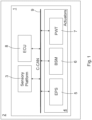
- the automotive sensory platform 3 may comprise traditional normal production ESC inertial Active Chassis sensors comprising longitudinal and lateral acceleration sensors, yaw rate sensors, and environment sensors including a (dual antenna) GNSS receiver, one or different forward-looking stereo cameras, a normal production forward-looking camera, one or different lidar sensors, one or more radar sensors, and a number of ultrasonic sensors.
- traditional normal production ESC inertial Active Chassis sensors comprising longitudinal and lateral acceleration sensors, yaw rate sensors, and environment sensors including a (dual antenna) GNSS receiver, one or different forward-looking stereo cameras, a normal production forward-looking camera, one or different lidar sensors, one or more radar sensors, and a number of ultrasonic sensors.
- BSM 6 represents a functional interface to realize acceleration and deceleration actions on the motor-vehicle 2.
- the ECU 8 provides on the C-CAN 9 a functional channel able to be a gateway of acceleration / positive torque to the powertrain ECU (ECM) and the way to decelerate the motor-vehicle 2 by brakes.
- the normal production parking longitudinal interface has been modified in order to achieve technical targets of present invention.
- Dual Dry Clutch Transmission (DDCT) ECU software has been modified in order to manage the longitudinal manoeuvres from/to 0/15 km/h around to 0 Nm of engine torque in a comfortable way.
- DDCT Dual Dry Clutch Transmission
- the Applicant has experienced that well-known dynamic models currently used for Trajectory Planning and Control for low-speed manoeuvres are undefined or ill-conditioned at low speeds.
- the Kinematic Bicycle Model a Consistent Model for Planning Feasible Trajectories for Autonomous Vehicles, IEEE Intelligent Vehicles Symposium (IV), 2017 , and Kong et al.
- Kinematic and dynamic vehicle models for autonomous driving control design in 2015 IEEE Intelligent Vehicles Symposium 2015, pp. 1094-1099 , the model used for low speed applications (0 ⁇ 20 km/h) is the kinematic bicycle model.
- the 4-DoF (Degree of Freedom) kinematic bicycle model is one of the simplest models used in motion planning.
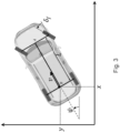
- Figure 3 shows the inertial and motor-vehicle reference frames for lateral control, in which the two left and right front wheels are represented by one single wheel at point A and the rear wheels are represented by one central rear wheel at point B.
- the steering angles of the front and rear wheels are represented by ⁇ f and ⁇ r , respectively.
- x and y are the Cartesian coordinates of the motor-vehicle's rear wheel, while ⁇ describes the orientation (yaw angle) of the motor-vehicle, v and a denote the velocity and longitudinal acceleration, respectively.
- the described kinematic model is nonlinear, so, as described by Oyama K. et al., Model predictive parking control for non-holonomic vehicles using time-state control form, in 2013 European Control Conference, 458-465 , a time-state control form described by Kiyota H. et al., A control of a class of nonholonomic systems with drift using time-state control form, IFAC Nonlinear Control Systems Design, Enschede, The Netherlands, 757-762 (1998 ), may be used.
- Kiyota H. et al. A control of a class of nonholonomic systems with drift using time-state control form, IFAC Nonlinear Control Systems Design, Enschede, The Netherlands, 757-762 (1998 ), may be used.
- This approach results in the lateral dynamics being linearized and representable as a differential equation w.r.t. the state (x) instead of time.
- the point-mass model is not used for design lateral controllers due to their large modelling errors.
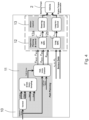
- Figure 4 shows a general block diagram of a dynamics control system 10 designed to control lateral and longitudinal dynamics of the motor-vehicle 2 during performance of low-speed manoeuvres in automated driving.
- the dynamics control system 10 may be entirely implemented by the ECU 8 or its implementation may be distributed among different ECUs, according to a proprietary logical architecture that the automotive manufacturer will decide to adopt.
- the dynamics control system 10 is designed to implement a Driving Path Planner 11 designed to receive data representative of static obstacles, such as roads, buildings, etc., in the surroundings of the motor-vehicle 2 and representing static space constraints to the motion of the motor-vehicle 2, and to compute a planned driving path for the motor-vehicle 2 during a low-speed manoeuvres performed in automated driving based on the positions of the static obstacles in the surroundings of the motor-vehicle 2 by implementing an algorithm fusion between techniques known in the literature, e.g., a Voronoi decomposition and A* path search algorithm.
- a Driving Path Planner 11 designed to receive data representative of static obstacles, such as roads, buildings, etc., in the surroundings of the motor-vehicle 2 and representing static space constraints to the motion of the motor-vehicle 2, and to compute a planned driving path for the motor-vehicle 2 during a low-speed manoeuvres performed in automated driving based on the positions of the static obstacles in the surroundings of the motor-vehicle 2
- the Driving Path Planner 11 is designed to compute the planned driving path as an obstacle-free driving corridor within which the motor-vehicle 2 may be driven and made up of a series of driving path segments each with a length and an orientation referenced in an inertial (or absolute) reference frame.
- the dynamics control system 10 is further designed to implement a Model Predictive Control (MPC)-based Trajectory Planner and Controller 12 designed to receive from the Driving Path Planner 11 data representative of the planned driving path of the motor-vehicle 2 and to compute, based thereon, a planned lateral trajectory and a planned longitudinal trajectory of the motor-vehicle 2, as described in more detail in the following.
- MPC Model Predictive Control
- the MPC-based Trajectory Planner and Controller 12 comprises two distinct MPC-based Trajectory Planners and Controllers, a Lateral Trajectory Planner and Controller 12a designed to plan and control the Lateral dynamics, and a Longitudinal Trajectory Planner and Controller 12b designed to plan and control the Longitudinal dynamics.
- the Lateral Trajectory Planner and Controller 12a is designed to compute the planned lateral trajectory as a series of steering requests ⁇ along the planned driving path in a motor-vehicle reference frame
- the Longitudinal Trajectory Planner and Controller 12b is designed to compute the planned longitudinal trajectory as a series of longitudinal acceleration requests a of the motor-vehicle 2 along the planned driving path;
- MPC Model Predictive Control
- MPC can manage future reference profiles and constraints and anticipate control actions accordingly. These limits may be imposed on any part of the system variables, such as states, outputs, inputs, and considering main actuators characteristics and operative limitations.
- the dynamics control system 10 is further designed to implement a Motion Controller 13 designed to receive from the Trajectory Planner and Controller 12 data representative of the planned lateral a longitudinal trajectories and to compute appropriate commands for the automated driving system 1, as described in more detail in the following.
- the MPC-based Lateral Trajectory Planner and Controller 12a controls the motor-vehicle lateral dynamics to track the optimal path according to constraints on the steering limitation and obstacle-free driving corridor.
- ⁇ s is the step w.r.t. the time-state x (positive or negative respectively for forward or backward motion), i.e., ⁇ s is not a time step, but it's the delta distance of movement along x.
- Equation (16) may be rewritten as follows: tan ⁇ min ⁇ ⁇ z 3 ⁇ 2 ⁇ tan ⁇ max
- the present invention overcomes these problems by dynamically (and smoothly) modifying the relative orientation of the motor-vehicle reference frame and the inertial reference frame along the planned driving path, in particular by dynamically (and smoothly) rotating the motor-vehicle reference frame relative to the inertial reference frame, so as to prevent ⁇ from being higher than ⁇ /2.
- Rotation of the motor-vehicle reference frame relative to the inertial reference frame amounts to a corresponding rotation of the planned driving path relative to inertial reference frame, so resulting in the planned driving path failing to exhibit bends greater than ⁇ /2.
- control technique is the linear MPC. This allows speed reference and obstacle tracking to be managed in a single integrated approach.
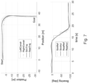
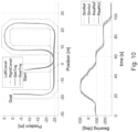
- ⁇ is the longitudinal position of the motor-vehicle 2 from the start of the planned driving path
- v is the longitudinal speed
- ⁇ t is the time step between two computation time instants.
Landscapes
- Engineering & Computer Science (AREA)
- Mechanical Engineering (AREA)
- Transportation (AREA)
- Automation & Control Theory (AREA)
- Human Computer Interaction (AREA)
- Combustion & Propulsion (AREA)
- Chemical & Material Sciences (AREA)
- Control Of Position, Course, Altitude, Or Attitude Of Moving Bodies (AREA)
- Physics & Mathematics (AREA)
- Mathematical Physics (AREA)
- Feedback Control In General (AREA)
- Electric Propulsion And Braking For Vehicles (AREA)
- Steering Control In Accordance With Driving Conditions (AREA)
Claims (6)
- Elektronisches Automobil-Dynamiksteuersystem (10) für ein Kraftfahrzeug (2), das mit einem automatisierten Automobilfahrsystem (1) ausgerüstet ist, das dazu konfiguriert ist, das Kraftfahrzeug (2) dazu zu veranlassen, Niedriggeschwindigkeitsmanöver beim automatisierten Fahren durchzuführen;wobei das automatisierte Automobilfahrsystem (1) Folgendes umfasst:- ein Automobilsensorsystem (3), das dazu konzipiert ist, kraftfahrzeugbezogene Größen abzutasten, und- Automobilaktuatoren (4), die eine elektrische Servolenkung (5), ein Bremssystem (6) und einen Antriebsstrang (7) umfassen;wobei das elektronische Dynamiksteuersystem (10) dazu konzipiert ist, Folgendes umzusetzen:- einen Fahrwegplaner (11), der konzipiert ist zum:∘ Empfangen von Daten, die statische Hindernisse in der Umgebung des Kraftfahrzeugs (2) darstellen und statische Raumauflagen für die Bewegung des Kraftfahrzeugs (2) auferlegen, und∘ Berechnen, basierend auf den empfangenen Daten, eines geplanten Fahrwegs für das Kraftfahrzeug (2) während eines Niedriggeschwindigkeitsmanövers, das beim automatisierten Fahren durchgeführt wird;- einen Bahnplaner und -controller (12) basierend auf modellprädiktiver Steuerung (MPC), der dazu konzipiert ist:∘ von dem Fahrwegplaner (11) Daten, die den geplanten Fahrweg darstellen, und von dem Automobilsensorsystem (3) Daten, die Positionen und Ausrichtungen des Kraftfahrzeugs (2) und dynamischer Hindernisse in der Umgebung des Kraftfahrzeugs (2) darstellen und dynamische Raumauflagen für die Bewegung des Kraftfahrzeugs (2) darstellen, zu empfangen, und∘ basierend auf den empfangenen Daten eine geplante seitliche Bahn und eine geplante Längsbahn für das Kraftfahrzeug (2) während des Niedriggeschwindigkeitsmanövers während des automatisierten Fahrens zu berechnen; und- einen Bewegungscontroller (13), der dazu konzipiert ist:∘ von dem Bahnplaner und -controller (12) Daten, die die geplanten seitlichen und Längsbahnen darstellen, zu empfangen, und∘ Befehle für die elektrische Servolenkung (5) basierend auf der geplanten seitlichen Bahn und für das Bremssystem (6) und den Antriebsstrang (7) basierend auf der geplanten Längsbahn zu berechnen;der Fahrwegplaner (11) dazu konzipiert ist, den geplanten Fahrweg als einen hindernisfreien Fahrkorridor zu berechnen, in dem das Kraftfahrzeug (2) gefahren werden kann und der aus einer Reihe von Fahrwegsegmenten jeweils mit einer Länge und einer Ausrichtung besteht, die in einem inertialen Referenzrahmen referenziert sind;wobei der MPC-basierte Bahnplaner und -controller (12) Folgendes umfasst:- einen MPC-basierten Seitenbahnplaner und -controller (12a), der dazu konzipiert ist, die geplante seitliche Bahn als eine Reihe von Lenkanforderungen (δ), die in einem Kraftfahrzeug -Referenzrahmen referenziert sind, zu berechnen; und- einen MPC -basierten Längsbahnplaner und -controller (12b), der dazu konzipiert ist, die geplante Längsbahn als eine Reihe von Längsbeschleunigungsanforderungen (a) zu berechnen;der Seitenbahnplaner und -controller (12a) weiter dazu konzipiert ist, die geplante seitliche Bahn basierend auf einem linearisierten Modell zu berechnen, das eine Darstellungssingularität jedes Mal dann darlegt, wenn die relative Ausrichtung eines Paares aufeinanderfolgender Fahrwegsegmente des geplanten Fahrwegs gleich oder höher als eine gegebene Menge ist;der Seitenbahnplaner und -controller (12a) weiter dazu konzipiert ist, dynamisch die relative Ausrichtung (θROT) des Kraftfahrzeug -Referenzrahmens und des inertialen Referenzrahmens entlang des geplanten Fahrwegs zu modifizieren, um zu veranlassen, dass die relativen Ausrichtungen aller Paare aufeinanderfolgender Fahrwegsegmente des geplanten Fahrwegs niedriger sind als die gegebene Menge.
- Elektronisches Automobil -Dynamiksteuersystem (1) nach Anspruch 1, wobei der Seitenbahnplaner und -controller (12a) weiter dazu konzipiert ist, die Ausrichtung (θROT ) des Kraftfahrzeug-Referenzrahmens relativ zu dem inertialen Referenzrahmen basierend auf der Ausrichtung (θi ) des Fahrwegsegments, das von dem Kraftfahrzeug (2) aktuell befahren wird, und auf der Ausrichtung (θi+1 ) des nächsten Fahrwegsegments zu berechnen.
- Elektronisches Automobil-Dynamiksteuersystem (1) nach Anspruch 2, wobei der Seitenbahnplaner und -controller (12a) weiter dazu konzipiert ist, die Ausrichtung (θROT ) des Kraftfahrzeug-Referenzrahmens relativ zu dem inertialen Referenzrahmen auch basierend auf der Ausrichtung (θ i+2 ) des zweiten nächsten Fahrwegsegments zu berechnen.
- Elektronisches Automobil-Dynamiksteuersystem (1) nach Anspruch 3, wobei der Seitenbahnplaner und -controller (12a) weiter dazu konzipiert ist, die relative Ausrichtung des Kraftfahrzeug-Referenzrahmens und des inertialen Referenzrahmens als eine lineare Interpolation der Ausrichtung (θi ) des Fahrwegsegments, das aktuell von dem Kraftfahrzeug (2) befahren wird, und der Ausrichtungen (θi+1, θi+2 ) des ersten und nächsten Fahrwegsegments zu berechnen.
- Elektronisches Automobil-Dynamiksteuersystem (1) nach Anspruch 4, wobei der Seitenbahnplaner und -controller (12a) weiter dazu konzipiert ist, die relative Ausrichtung des Kraftfahrzeug-Referenzrahmens und des inertialen Referenzrahmens zu berechnen als:
 θROT die Ausrichtung des Kraftfahrzeug-Referenzrahmens relativ zu dem inertialen Referenzrahmen ist,θi, θi+1, θi+2 die Ausrichtungen des Fahrwegsegments sind, das aktuell von dem Kraftfahrzeug (2) befahren wird, des ersten nächsten Fahrwegsegments und des zweiten nächsten Fahrwegsegments in dem inertialen Referenzrahmen,W ein Gewichtungsfaktor ist,xv,yv die aktuellen Koordinaten des Kraftfahrzeugs in dem inertialen Referenzrahmen sind,d der euklidische Abstand zwischen der aktuellen Position des Kraftfahrzeugs (2) und dem Ende des Fahrwegsegments ist, das die aktuelle Position des Kraftfahrzeugs (2) enthält, unddi+1,i die Länge des nächsten Fahrwegsegments zu dem einen, das die aktuelle Position des Kraftfahrzeugs (2) enthält, ist.
 - Software, die in eine elektronische Automobilsteuereinheit (8) ladbar und dazu konzipiert ist, wenn sie ausgeführt wird zu veranlassen, dass die elektronische Automobilsteuereinheit (8) dazu konfiguriert wird, das elektronische Automobil-Dynamiksteuersystem (10) wie in einem der vorstehenden Ansprüche beansprucht umzusetzen.
Applications Claiming Priority (3)
| Application Number | Priority Date | Filing Date | Title |
|---|---|---|---|
| EP19204949 | 2019-10-23 | ||
| IT102020000009100A IT202000009100A1 (it) | 2020-04-27 | 2020-04-27 | Pianificazione e controllo della traiettoria di un autoveicolo autonomo per la realizzazione di manovre a bassa velocita' in guida autonoma |
| PCT/IB2020/059987 WO2021079338A1 (en) | 2019-10-23 | 2020-10-23 | Motor-vehicle trajectory planning and control to cause automated motor-vehicles to perform low-speed manoeuvres in automated driving |
Publications (2)
| Publication Number | Publication Date |
|---|---|
| EP4048567A1 EP4048567A1 (de) | 2022-08-31 |
| EP4048567B1 true EP4048567B1 (de) | 2025-04-02 |
Family
ID=73014561
Family Applications (1)
| Application Number | Title | Priority Date | Filing Date |
|---|---|---|---|
| EP20797200.1A Active EP4048567B1 (de) | 2019-10-23 | 2020-10-23 | Trajektorienplanung für kraftfahrzeug und steuerung zur veranlassung von automatisierten motorfahrzeugen zur durchführung von fahrmanövern mit niedriger geschwindigkeit im automatisierten fahrbetrieb |
Country Status (3)
| Country | Link |
|---|---|
| US (1) | US11970157B2 (de) |
| EP (1) | EP4048567B1 (de) |
| WO (1) | WO2021079338A1 (de) |
Families Citing this family (19)
| Publication number | Priority date | Publication date | Assignee | Title |
|---|---|---|---|---|
| US11884302B2 (en) * | 2019-11-15 | 2024-01-30 | Massachusetts Institute Of Technology | Social behavior for autonomous vehicles |
| CN113320542B (zh) * | 2021-06-24 | 2022-05-17 | 厦门大学 | 一种自动驾驶车辆的跟踪控制方法 |
| CN113734183B (zh) * | 2021-09-17 | 2023-05-02 | 京东鲲鹏(江苏)科技有限公司 | 基于转向迟滞的车辆控制方法、装置、设备及存储介质 |
| CN113978547B (zh) * | 2021-10-21 | 2022-08-02 | 江铃汽车股份有限公司 | 自动驾驶转向控制方法及系统 |
| CN114139787B (zh) * | 2021-11-23 | 2024-12-31 | 北京科技大学 | 一种铰接式采矿装备交叉口转弯最优轨迹规划方法及系统 |
| CN114255594B (zh) * | 2021-12-28 | 2024-03-15 | 吉林大学 | 一种自主代客泊车运动规划与运动控制方法 |
| CN114312847B (zh) * | 2022-01-13 | 2024-04-12 | 安徽江淮汽车集团股份有限公司 | 一种自动驾驶车辆的横向控制方法及装置 |
| CN114689344B (zh) * | 2022-04-19 | 2025-09-05 | 上海测迅汽车科技有限公司 | 自动驾驶系统智能检测装置 |
| CN114924561B (zh) * | 2022-05-09 | 2025-05-23 | 重庆大学 | 一种四舵轮agv轨迹跟踪控制方法 |
| US12145582B2 (en) * | 2022-06-23 | 2024-11-19 | Ford Global Technologies, Llc | Systems and methods for controlling longitudinal acceleration based on lateral objects |
| CN115140098B (zh) * | 2022-08-01 | 2025-08-12 | 江西吉利新能源商用车有限公司 | 目标锁定方法、装置、设备及可读存储介质 |
| IT202200022308A1 (it) * | 2022-10-28 | 2024-04-28 | Fiat Ricerche | Pianificazione di traiettoria a bassa velocita' basata su un modello di controllo predittivo con evitamento di ostacoli dinamici in ambienti non strutturati |
| IT202200024228A1 (it) | 2022-11-24 | 2024-05-24 | Fiat Ricerche | Pianificazione di traiettoria a bassa velocita' basata su un modello di controllo predittivo con evitamento di ostacoli dinamici in ambienti non strutturati |
| IT202200024234A1 (it) | 2022-11-24 | 2024-05-24 | Fiat Ricerche | Pianificazione di traiettoria a bassa velocita' basata su un modello di controllo predittivo con evitamento di ostacoli dinamici in ambienti non strutturati |
| IT202200024936A1 (it) | 2022-12-02 | 2024-06-02 | Fiat Ricerche | Pianificazione di traiettoria a bassa velocita' basata su un modello di controllo predittivo con evitamento di ostacoli dinamici in ambienti non strutturati |
| CN116224802B (zh) * | 2023-03-31 | 2023-12-05 | 上海理工大学 | 基于干扰观测器和管道模型预测的车队纵向复合控制方法 |
| CN116540737B (zh) * | 2023-06-13 | 2026-02-06 | 吉林大学 | 一种静态避障场景下考虑驾驶习惯的路径规划与控制方法 |
| CN117601857B (zh) | 2023-12-18 | 2024-05-10 | 广东工业大学 | 一种基于轨迹预测的人机共驾切换控制方法 |
| CN120828825A (zh) * | 2024-04-22 | 2025-10-24 | 北京魔门塔科技有限公司 | 车辆控制方法、装置、电子设备及介质 |
Family Cites Families (2)
| Publication number | Priority date | Publication date | Assignee | Title |
|---|---|---|---|---|
| US10589739B2 (en) * | 2017-04-13 | 2020-03-17 | GM Global Technology Operations LLC | Automated driving commands interpretation for stability control |
| US20200001920A1 (en) * | 2018-07-02 | 2020-01-02 | Ohio State Innovation Foundation | Systems and methods for preventing a jackknife condition in a tractor-trailer system |
-
2020
- 2020-10-23 WO PCT/IB2020/059987 patent/WO2021079338A1/en not_active Ceased
- 2020-10-23 US US17/442,379 patent/US11970157B2/en active Active
- 2020-10-23 EP EP20797200.1A patent/EP4048567B1/de active Active
Also Published As
| Publication number | Publication date |
|---|---|
| US20220169247A1 (en) | 2022-06-02 |
| US11970157B2 (en) | 2024-04-30 |
| EP4048567A1 (de) | 2022-08-31 |
| WO2021079338A1 (en) | 2021-04-29 |
Similar Documents
| Publication | Publication Date | Title |
|---|---|---|
| EP4048567B1 (de) | Trajektorienplanung für kraftfahrzeug und steuerung zur veranlassung von automatisierten motorfahrzeugen zur durchführung von fahrmanövern mit niedriger geschwindigkeit im automatisierten fahrbetrieb | |
| EP4031428B1 (de) | Modellbasierter entwurf einer trajektorienplanung und -steuerung für automatisierte kraftfahrzeuge in einer dynamischen umgebung | |
| Li et al. | Advanced motion control and sensing for intelligent vehicles | |
| Hatipoglu et al. | Automated lane change controller design | |
| Gao et al. | Predictive control of autonomous ground vehicles with obstacle avoidance on slippery roads | |
| Ferrara et al. | Second order sliding mode control of vehicles with distributed collision avoidance capabilities | |
| Attia et al. | Coupled longitudinal and lateral control strategy improving lateral stability for autonomous vehicle | |
| Caporale et al. | Towards the design of robotic drivers for full-scale self-driving racing cars | |
| US12576907B2 (en) | Model predictive brake-to-steer control for automated vehicles | |
| CN108717268A (zh) | 基于最优控制与安全距离的自动驾驶最速操纵控制系统及其控制方法 | |
| Koga et al. | Realization of different driving characteristics for autonomous vehicle by using model predictive control | |
| KR20230166124A (ko) | 장치의 액츄에이터를 자율적으로 구동하기 위한 방법 | |
| Bouzidi et al. | Interaction-aware merging in mixed traffic with integrated game-theoretic predictive control and inverse differential game | |
| Sattel et al. | Ground vehicle guidance along collision-free trajectories using elastic bands | |
| US12371009B2 (en) | Method for automated steering of a motor vehicle | |
| Kim et al. | Experimental verification of the power slide driving technique for control strategy of autonomous race cars | |
| Nilsson et al. | Driver model based automated driving of long vehicle combinations in emulated highway traffic | |
| EP4608699A1 (de) | Modellprädiktive steuerungsbasierte bahnplanung mit niedriger geschwindigkeit mit dynamischer hindernisvermeidung in unstrukturierten umgebungen | |
| Borrello et al. | Trajectory Planning and Vehicle Control at low speed for home zone manoeuvres | |
| Borrello et al. | Trajectory planning based on model predictive control with dynamic obstacle avoidance in unstructured environments | |
| Trotta et al. | A feedback linearization based approach for fully autonomous adaptive cruise control | |
| Ghumman et al. | Guidance-based on-line motion planning for autonomous highway overtaking | |
| Kranz et al. | Nonlinear lateral vehicle control in combined emergency steering and braking maneuvers | |
| Chen et al. | Integrated forward and reverse trajectory tracking control for car-like ground vehicle | |
| WO2024110919A1 (en) | Electronic control system for a motor-vehicle |
Legal Events
| Date | Code | Title | Description |
|---|---|---|---|
| STAA | Information on the status of an ep patent application or granted ep patent |
Free format text: STATUS: UNKNOWN |
|
| STAA | Information on the status of an ep patent application or granted ep patent |
Free format text: STATUS: THE INTERNATIONAL PUBLICATION HAS BEEN MADE |
|
| PUAI | Public reference made under article 153(3) epc to a published international application that has entered the european phase |
Free format text: ORIGINAL CODE: 0009012 |
|
| STAA | Information on the status of an ep patent application or granted ep patent |
Free format text: STATUS: REQUEST FOR EXAMINATION WAS MADE |
|
| 17P | Request for examination filed |
Effective date: 20210917 |
|
| AK | Designated contracting states |
Kind code of ref document: A1 Designated state(s): AL AT BE BG CH CY CZ DE DK EE ES FI FR GB GR HR HU IE IS IT LI LT LU LV MC MK MT NL NO PL PT RO RS SE SI SK SM TR |
|
| DAV | Request for validation of the european patent (deleted) | ||
| DAX | Request for extension of the european patent (deleted) | ||
| STAA | Information on the status of an ep patent application or granted ep patent |
Free format text: STATUS: EXAMINATION IS IN PROGRESS |
|
| 17Q | First examination report despatched |
Effective date: 20230616 |
|
| GRAP | Despatch of communication of intention to grant a patent |
Free format text: ORIGINAL CODE: EPIDOSNIGR1 |
|
| STAA | Information on the status of an ep patent application or granted ep patent |
Free format text: STATUS: GRANT OF PATENT IS INTENDED |
|
| INTG | Intention to grant announced |
Effective date: 20241105 |
|
| RIC1 | Information provided on ipc code assigned before grant |
Ipc: B62D 15/02 20060101ALI20241025BHEP Ipc: G05D 1/00 20060101ALI20241025BHEP Ipc: B60W 50/00 20060101ALI20241025BHEP Ipc: B60W 30/06 20060101AFI20241025BHEP |
|
| GRAS | Grant fee paid |
Free format text: ORIGINAL CODE: EPIDOSNIGR3 |
|
| GRAA | (expected) grant |
Free format text: ORIGINAL CODE: 0009210 |
|
| STAA | Information on the status of an ep patent application or granted ep patent |
Free format text: STATUS: THE PATENT HAS BEEN GRANTED |
|
| AK | Designated contracting states |
Kind code of ref document: B1 Designated state(s): AL AT BE BG CH CY CZ DE DK EE ES FI FR GB GR HR HU IE IS IT LI LT LU LV MC MK MT NL NO PL PT RO RS SE SI SK SM TR |
|
| REG | Reference to a national code |
Ref country code: GB Ref legal event code: FG4D |
|
| REG | Reference to a national code |
Ref country code: CH Ref legal event code: EP |
|
| REG | Reference to a national code |
Ref country code: IE Ref legal event code: FG4D |
|
| REG | Reference to a national code |
Ref country code: DE Ref legal event code: R096 Ref document number: 602020048808 Country of ref document: DE |
|
| REG | Reference to a national code |
Ref country code: NL Ref legal event code: MP Effective date: 20250402 |
|
| PG25 | Lapsed in a contracting state [announced via postgrant information from national office to epo] |
Ref country code: NL Free format text: LAPSE BECAUSE OF FAILURE TO SUBMIT A TRANSLATION OF THE DESCRIPTION OR TO PAY THE FEE WITHIN THE PRESCRIBED TIME-LIMIT Effective date: 20250402 |
|
| REG | Reference to a national code |
Ref country code: AT Ref legal event code: MK05 Ref document number: 1781031 Country of ref document: AT Kind code of ref document: T Effective date: 20250402 |
|
| PG25 | Lapsed in a contracting state [announced via postgrant information from national office to epo] |
Ref country code: FI Free format text: LAPSE BECAUSE OF FAILURE TO SUBMIT A TRANSLATION OF THE DESCRIPTION OR TO PAY THE FEE WITHIN THE PRESCRIBED TIME-LIMIT Effective date: 20250402 Ref country code: ES Free format text: LAPSE BECAUSE OF FAILURE TO SUBMIT A TRANSLATION OF THE DESCRIPTION OR TO PAY THE FEE WITHIN THE PRESCRIBED TIME-LIMIT Effective date: 20250402 Ref country code: PT Free format text: LAPSE BECAUSE OF FAILURE TO SUBMIT A TRANSLATION OF THE DESCRIPTION OR TO PAY THE FEE WITHIN THE PRESCRIBED TIME-LIMIT Effective date: 20250804 |
|
| REG | Reference to a national code |
Ref country code: LT Ref legal event code: MG9D |
|
| PG25 | Lapsed in a contracting state [announced via postgrant information from national office to epo] |
Ref country code: NO Free format text: LAPSE BECAUSE OF FAILURE TO SUBMIT A TRANSLATION OF THE DESCRIPTION OR TO PAY THE FEE WITHIN THE PRESCRIBED TIME-LIMIT Effective date: 20250702 Ref country code: GR Free format text: LAPSE BECAUSE OF FAILURE TO SUBMIT A TRANSLATION OF THE DESCRIPTION OR TO PAY THE FEE WITHIN THE PRESCRIBED TIME-LIMIT Effective date: 20250703 |
|
| PG25 | Lapsed in a contracting state [announced via postgrant information from national office to epo] |
Ref country code: PL Free format text: LAPSE BECAUSE OF FAILURE TO SUBMIT A TRANSLATION OF THE DESCRIPTION OR TO PAY THE FEE WITHIN THE PRESCRIBED TIME-LIMIT Effective date: 20250402 |
|
| PG25 | Lapsed in a contracting state [announced via postgrant information from national office to epo] |
Ref country code: BG Free format text: LAPSE BECAUSE OF FAILURE TO SUBMIT A TRANSLATION OF THE DESCRIPTION OR TO PAY THE FEE WITHIN THE PRESCRIBED TIME-LIMIT Effective date: 20250402 |
|
| PG25 | Lapsed in a contracting state [announced via postgrant information from national office to epo] |
Ref country code: HR Free format text: LAPSE BECAUSE OF FAILURE TO SUBMIT A TRANSLATION OF THE DESCRIPTION OR TO PAY THE FEE WITHIN THE PRESCRIBED TIME-LIMIT Effective date: 20250402 |
|
| PG25 | Lapsed in a contracting state [announced via postgrant information from national office to epo] |
Ref country code: AT Free format text: LAPSE BECAUSE OF FAILURE TO SUBMIT A TRANSLATION OF THE DESCRIPTION OR TO PAY THE FEE WITHIN THE PRESCRIBED TIME-LIMIT Effective date: 20250402 |
|
| PGFP | Annual fee paid to national office [announced via postgrant information from national office to epo] |
Ref country code: FR Payment date: 20250923 Year of fee payment: 6 |
|
| PG25 | Lapsed in a contracting state [announced via postgrant information from national office to epo] |
Ref country code: RS Free format text: LAPSE BECAUSE OF FAILURE TO SUBMIT A TRANSLATION OF THE DESCRIPTION OR TO PAY THE FEE WITHIN THE PRESCRIBED TIME-LIMIT Effective date: 20250702 |
|
| PG25 | Lapsed in a contracting state [announced via postgrant information from national office to epo] |
Ref country code: IS Free format text: LAPSE BECAUSE OF FAILURE TO SUBMIT A TRANSLATION OF THE DESCRIPTION OR TO PAY THE FEE WITHIN THE PRESCRIBED TIME-LIMIT Effective date: 20250802 |
|
| PG25 | Lapsed in a contracting state [announced via postgrant information from national office to epo] |
Ref country code: LV Free format text: LAPSE BECAUSE OF FAILURE TO SUBMIT A TRANSLATION OF THE DESCRIPTION OR TO PAY THE FEE WITHIN THE PRESCRIBED TIME-LIMIT Effective date: 20250402 |
|
| REG | Reference to a national code |
Ref country code: DE Ref legal event code: R097 Ref document number: 602020048808 Country of ref document: DE |
|
| PGFP | Annual fee paid to national office [announced via postgrant information from national office to epo] |
Ref country code: DE Payment date: 20250923 Year of fee payment: 6 |
|
| PG25 | Lapsed in a contracting state [announced via postgrant information from national office to epo] |
Ref country code: DK Free format text: LAPSE BECAUSE OF FAILURE TO SUBMIT A TRANSLATION OF THE DESCRIPTION OR TO PAY THE FEE WITHIN THE PRESCRIBED TIME-LIMIT Effective date: 20250402 Ref country code: SM Free format text: LAPSE BECAUSE OF FAILURE TO SUBMIT A TRANSLATION OF THE DESCRIPTION OR TO PAY THE FEE WITHIN THE PRESCRIBED TIME-LIMIT Effective date: 20250402 |
|
| PG25 | Lapsed in a contracting state [announced via postgrant information from national office to epo] |
Ref country code: CZ Free format text: LAPSE BECAUSE OF FAILURE TO SUBMIT A TRANSLATION OF THE DESCRIPTION OR TO PAY THE FEE WITHIN THE PRESCRIBED TIME-LIMIT Effective date: 20250402 |
|
| PG25 | Lapsed in a contracting state [announced via postgrant information from national office to epo] |
Ref country code: EE Free format text: LAPSE BECAUSE OF FAILURE TO SUBMIT A TRANSLATION OF THE DESCRIPTION OR TO PAY THE FEE WITHIN THE PRESCRIBED TIME-LIMIT Effective date: 20250402 |
|
| PG25 | Lapsed in a contracting state [announced via postgrant information from national office to epo] |
Ref country code: SK Free format text: LAPSE BECAUSE OF FAILURE TO SUBMIT A TRANSLATION OF THE DESCRIPTION OR TO PAY THE FEE WITHIN THE PRESCRIBED TIME-LIMIT Effective date: 20250402 |
|
| PG25 | Lapsed in a contracting state [announced via postgrant information from national office to epo] |
Ref country code: IT Free format text: LAPSE BECAUSE OF FAILURE TO SUBMIT A TRANSLATION OF THE DESCRIPTION OR TO PAY THE FEE WITHIN THE PRESCRIBED TIME-LIMIT Effective date: 20250402 |
|
| PLBE | No opposition filed within time limit |
Free format text: ORIGINAL CODE: 0009261 |
|
| STAA | Information on the status of an ep patent application or granted ep patent |
Free format text: STATUS: NO OPPOSITION FILED WITHIN TIME LIMIT |
|
| PG25 | Lapsed in a contracting state [announced via postgrant information from national office to epo] |
Ref country code: RO Free format text: LAPSE BECAUSE OF FAILURE TO SUBMIT A TRANSLATION OF THE DESCRIPTION OR TO PAY THE FEE WITHIN THE PRESCRIBED TIME-LIMIT Effective date: 20250402 |
|
| REG | Reference to a national code |
Ref country code: CH Ref legal event code: L10 Free format text: ST27 STATUS EVENT CODE: U-0-0-L10-L00 (AS PROVIDED BY THE NATIONAL OFFICE) Effective date: 20260211 |
|
| 26N | No opposition filed |
Effective date: 20260105 |