EP4031428B1 - Modellbasierter entwurf einer trajektorienplanung und -steuerung für automatisierte kraftfahrzeuge in einer dynamischen umgebung - Google Patents
Modellbasierter entwurf einer trajektorienplanung und -steuerung für automatisierte kraftfahrzeuge in einer dynamischen umgebung Download PDFInfo
- Publication number
- EP4031428B1 EP4031428B1 EP20775727.9A EP20775727A EP4031428B1 EP 4031428 B1 EP4031428 B1 EP 4031428B1 EP 20775727 A EP20775727 A EP 20775727A EP 4031428 B1 EP4031428 B1 EP 4031428B1
- Authority
- EP
- European Patent Office
- Prior art keywords
- vehicle
- longitudinal
- lateral
- motor
- trajectory
- Prior art date
- Legal status (The legal status is an assumption and is not a legal conclusion. Google has not performed a legal analysis and makes no representation as to the accuracy of the status listed.)
- Active
Links
Images


Classifications
-
- B—PERFORMING OPERATIONS; TRANSPORTING
- B60—VEHICLES IN GENERAL
- B60W—CONJOINT CONTROL OF VEHICLE SUB-UNITS OF DIFFERENT TYPE OR DIFFERENT FUNCTION; CONTROL SYSTEMS SPECIALLY ADAPTED FOR HYBRID VEHICLES; ROAD VEHICLE DRIVE CONTROL SYSTEMS FOR PURPOSES NOT RELATED TO THE CONTROL OF A PARTICULAR SUB-UNIT
- B60W30/00—Purposes of road vehicle drive control systems not related to the control of a particular sub-unit, e.g. of systems using conjoint control of vehicle sub-units
- B60W30/18—Propelling the vehicle
- B60W30/18009—Propelling the vehicle related to particular drive situations
- B60W30/18163—Lane change; Overtaking manoeuvres
-
- B—PERFORMING OPERATIONS; TRANSPORTING
- B60—VEHICLES IN GENERAL
- B60W—CONJOINT CONTROL OF VEHICLE SUB-UNITS OF DIFFERENT TYPE OR DIFFERENT FUNCTION; CONTROL SYSTEMS SPECIALLY ADAPTED FOR HYBRID VEHICLES; ROAD VEHICLE DRIVE CONTROL SYSTEMS FOR PURPOSES NOT RELATED TO THE CONTROL OF A PARTICULAR SUB-UNIT
- B60W30/00—Purposes of road vehicle drive control systems not related to the control of a particular sub-unit, e.g. of systems using conjoint control of vehicle sub-units
- B60W30/08—Active safety systems predicting or avoiding probable or impending collision or attempting to minimise its consequences
- B60W30/09—Taking automatic action to avoid collision, e.g. braking and steering
-
- B—PERFORMING OPERATIONS; TRANSPORTING
- B60—VEHICLES IN GENERAL
- B60W—CONJOINT CONTROL OF VEHICLE SUB-UNITS OF DIFFERENT TYPE OR DIFFERENT FUNCTION; CONTROL SYSTEMS SPECIALLY ADAPTED FOR HYBRID VEHICLES; ROAD VEHICLE DRIVE CONTROL SYSTEMS FOR PURPOSES NOT RELATED TO THE CONTROL OF A PARTICULAR SUB-UNIT
- B60W30/00—Purposes of road vehicle drive control systems not related to the control of a particular sub-unit, e.g. of systems using conjoint control of vehicle sub-units
- B60W30/10—Path keeping
- B60W30/12—Lane keeping
-
- B—PERFORMING OPERATIONS; TRANSPORTING
- B60—VEHICLES IN GENERAL
- B60W—CONJOINT CONTROL OF VEHICLE SUB-UNITS OF DIFFERENT TYPE OR DIFFERENT FUNCTION; CONTROL SYSTEMS SPECIALLY ADAPTED FOR HYBRID VEHICLES; ROAD VEHICLE DRIVE CONTROL SYSTEMS FOR PURPOSES NOT RELATED TO THE CONTROL OF A PARTICULAR SUB-UNIT
- B60W60/00—Drive control systems specially adapted for autonomous road vehicles
- B60W60/001—Planning or execution of driving tasks
- B60W60/0011—Planning or execution of driving tasks involving control alternatives for a single driving scenario, e.g. planning several paths to avoid obstacles
-
- B—PERFORMING OPERATIONS; TRANSPORTING
- B60—VEHICLES IN GENERAL
- B60W—CONJOINT CONTROL OF VEHICLE SUB-UNITS OF DIFFERENT TYPE OR DIFFERENT FUNCTION; CONTROL SYSTEMS SPECIALLY ADAPTED FOR HYBRID VEHICLES; ROAD VEHICLE DRIVE CONTROL SYSTEMS FOR PURPOSES NOT RELATED TO THE CONTROL OF A PARTICULAR SUB-UNIT
- B60W60/00—Drive control systems specially adapted for autonomous road vehicles
- B60W60/001—Planning or execution of driving tasks
- B60W60/0027—Planning or execution of driving tasks using trajectory prediction for other traffic participants
- B60W60/00272—Planning or execution of driving tasks using trajectory prediction for other traffic participants relying on extrapolation of current movement
-
- B—PERFORMING OPERATIONS; TRANSPORTING
- B60—VEHICLES IN GENERAL
- B60W—CONJOINT CONTROL OF VEHICLE SUB-UNITS OF DIFFERENT TYPE OR DIFFERENT FUNCTION; CONTROL SYSTEMS SPECIALLY ADAPTED FOR HYBRID VEHICLES; ROAD VEHICLE DRIVE CONTROL SYSTEMS FOR PURPOSES NOT RELATED TO THE CONTROL OF A PARTICULAR SUB-UNIT
- B60W60/00—Drive control systems specially adapted for autonomous road vehicles
- B60W60/001—Planning or execution of driving tasks
- B60W60/0027—Planning or execution of driving tasks using trajectory prediction for other traffic participants
- B60W60/00276—Planning or execution of driving tasks using trajectory prediction for other traffic participants for two or more other traffic participants
-
- B—PERFORMING OPERATIONS; TRANSPORTING
- B60—VEHICLES IN GENERAL
- B60W—CONJOINT CONTROL OF VEHICLE SUB-UNITS OF DIFFERENT TYPE OR DIFFERENT FUNCTION; CONTROL SYSTEMS SPECIALLY ADAPTED FOR HYBRID VEHICLES; ROAD VEHICLE DRIVE CONTROL SYSTEMS FOR PURPOSES NOT RELATED TO THE CONTROL OF A PARTICULAR SUB-UNIT
- B60W2510/00—Input parameters relating to a particular sub-units
- B60W2510/20—Steering systems
- B60W2510/205—Steering speed
-
- B—PERFORMING OPERATIONS; TRANSPORTING
- B60—VEHICLES IN GENERAL
- B60W—CONJOINT CONTROL OF VEHICLE SUB-UNITS OF DIFFERENT TYPE OR DIFFERENT FUNCTION; CONTROL SYSTEMS SPECIALLY ADAPTED FOR HYBRID VEHICLES; ROAD VEHICLE DRIVE CONTROL SYSTEMS FOR PURPOSES NOT RELATED TO THE CONTROL OF A PARTICULAR SUB-UNIT
- B60W2520/00—Input parameters relating to overall vehicle dynamics
- B60W2520/06—Direction of travel
-
- B—PERFORMING OPERATIONS; TRANSPORTING
- B60—VEHICLES IN GENERAL
- B60W—CONJOINT CONTROL OF VEHICLE SUB-UNITS OF DIFFERENT TYPE OR DIFFERENT FUNCTION; CONTROL SYSTEMS SPECIALLY ADAPTED FOR HYBRID VEHICLES; ROAD VEHICLE DRIVE CONTROL SYSTEMS FOR PURPOSES NOT RELATED TO THE CONTROL OF A PARTICULAR SUB-UNIT
- B60W2520/00—Input parameters relating to overall vehicle dynamics
- B60W2520/10—Longitudinal speed
- B60W2520/105—Longitudinal acceleration
-
- B—PERFORMING OPERATIONS; TRANSPORTING
- B60—VEHICLES IN GENERAL
- B60W—CONJOINT CONTROL OF VEHICLE SUB-UNITS OF DIFFERENT TYPE OR DIFFERENT FUNCTION; CONTROL SYSTEMS SPECIALLY ADAPTED FOR HYBRID VEHICLES; ROAD VEHICLE DRIVE CONTROL SYSTEMS FOR PURPOSES NOT RELATED TO THE CONTROL OF A PARTICULAR SUB-UNIT
- B60W2520/00—Input parameters relating to overall vehicle dynamics
- B60W2520/12—Lateral speed
- B60W2520/125—Lateral acceleration
-
- B—PERFORMING OPERATIONS; TRANSPORTING
- B60—VEHICLES IN GENERAL
- B60W—CONJOINT CONTROL OF VEHICLE SUB-UNITS OF DIFFERENT TYPE OR DIFFERENT FUNCTION; CONTROL SYSTEMS SPECIALLY ADAPTED FOR HYBRID VEHICLES; ROAD VEHICLE DRIVE CONTROL SYSTEMS FOR PURPOSES NOT RELATED TO THE CONTROL OF A PARTICULAR SUB-UNIT
- B60W2520/00—Input parameters relating to overall vehicle dynamics
- B60W2520/14—Yaw
-
- B—PERFORMING OPERATIONS; TRANSPORTING
- B60—VEHICLES IN GENERAL
- B60W—CONJOINT CONTROL OF VEHICLE SUB-UNITS OF DIFFERENT TYPE OR DIFFERENT FUNCTION; CONTROL SYSTEMS SPECIALLY ADAPTED FOR HYBRID VEHICLES; ROAD VEHICLE DRIVE CONTROL SYSTEMS FOR PURPOSES NOT RELATED TO THE CONTROL OF A PARTICULAR SUB-UNIT
- B60W2520/00—Input parameters relating to overall vehicle dynamics
- B60W2520/28—Wheel speed
-
- B—PERFORMING OPERATIONS; TRANSPORTING
- B60—VEHICLES IN GENERAL
- B60W—CONJOINT CONTROL OF VEHICLE SUB-UNITS OF DIFFERENT TYPE OR DIFFERENT FUNCTION; CONTROL SYSTEMS SPECIALLY ADAPTED FOR HYBRID VEHICLES; ROAD VEHICLE DRIVE CONTROL SYSTEMS FOR PURPOSES NOT RELATED TO THE CONTROL OF A PARTICULAR SUB-UNIT
- B60W2540/00—Input parameters relating to occupants
- B60W2540/18—Steering angle
-
- B—PERFORMING OPERATIONS; TRANSPORTING
- B60—VEHICLES IN GENERAL
- B60W—CONJOINT CONTROL OF VEHICLE SUB-UNITS OF DIFFERENT TYPE OR DIFFERENT FUNCTION; CONTROL SYSTEMS SPECIALLY ADAPTED FOR HYBRID VEHICLES; ROAD VEHICLE DRIVE CONTROL SYSTEMS FOR PURPOSES NOT RELATED TO THE CONTROL OF A PARTICULAR SUB-UNIT
- B60W2552/00—Input parameters relating to infrastructure
- B60W2552/30—Road curve radius
-
- B—PERFORMING OPERATIONS; TRANSPORTING
- B60—VEHICLES IN GENERAL
- B60W—CONJOINT CONTROL OF VEHICLE SUB-UNITS OF DIFFERENT TYPE OR DIFFERENT FUNCTION; CONTROL SYSTEMS SPECIALLY ADAPTED FOR HYBRID VEHICLES; ROAD VEHICLE DRIVE CONTROL SYSTEMS FOR PURPOSES NOT RELATED TO THE CONTROL OF A PARTICULAR SUB-UNIT
- B60W2554/00—Input parameters relating to objects
- B60W2554/40—Dynamic objects, e.g. animals, windblown objects
- B60W2554/404—Characteristics
- B60W2554/4041—Position
-
- B—PERFORMING OPERATIONS; TRANSPORTING
- B60—VEHICLES IN GENERAL
- B60W—CONJOINT CONTROL OF VEHICLE SUB-UNITS OF DIFFERENT TYPE OR DIFFERENT FUNCTION; CONTROL SYSTEMS SPECIALLY ADAPTED FOR HYBRID VEHICLES; ROAD VEHICLE DRIVE CONTROL SYSTEMS FOR PURPOSES NOT RELATED TO THE CONTROL OF A PARTICULAR SUB-UNIT
- B60W2554/00—Input parameters relating to objects
- B60W2554/40—Dynamic objects, e.g. animals, windblown objects
- B60W2554/404—Characteristics
- B60W2554/4042—Longitudinal speed
Definitions
- the present invention relates to a model-based design of trajectory planning and control for automated motor-vehicles in dynamic environment.
- the invention finds application in any type of road motor-vehicles, regardless of whether it is used for the transportation of people, such as a car, a bus, a camper, etc., or for the transportation of goods, such as an industrial vehicle (truck, B-train, trailer truck, etc.) or a light or medium-heavy commercial vehicle (light van, van, pick-up trucks, etc.).
- an industrial vehicle truck, B-train, trailer truck, etc.
- a light or medium-heavy commercial vehicle light van, van, pick-up trucks, etc.
- trajectory will be used to indicate the position of a vehicle over a period of time, without worrying about velocity or higher order terms.
- Heuristic-based approaches usually apply artificial intelligence techniques, such as machine learning methods, search-based methods and random sampling methods.
- A* search-based method
- A* search-based method
- RRT Rapidly-exploring Random Tree - Random sampling methods
- [5] and [6] firstly defines some metrics for the proximity of two spatial points and samples random points in the space around the vehicle. Then, starting from the initial or the required end-position of the vehicle, the algorithm builds up a tree structure from the sampled points.
- the predefined metrics is added to the tree. The process is continued until a branch of the tree approaches the required final (or initial) point of the vehicle, and a path is then evaluated along the tree.
- SVM Small Vector Machine - Machine learning method
- Geometric based methods [8] and [9] design trajectories based on some parametric geometrical curves as clothoids or splines. These algorithms calculate the parameters of the curves with the consideration of geometrical constraints, such as the derivatives of the curve, the limited steering angle of the vehicle and the maximal allowed lateral acceleration ([10]).
- Geometric-based methods are suitable mainly for low speed applications such as automated parking but, at higher speeds, these can't consider the dynamic behaviour of vehicle and therefore its stability. Most of the geometric-based and heuristic-based methods generate paths instead of trajectories. To obtain a trajectory, some speed profile could be used to convert the computed path into a trajectory ([11]).
- Optimal control-based methods use optimal control techniques such as MPC (Model Predictive Control) and NLP (Nonlinear Programming) in order to generate the trajectory. Optimization techniques are used in [13] and [14] to find the appropriate control input sequence, i.e. steering wheel angle and vehicle longitudinal acceleration, that drives the vehicle to the desired end-point.
- the behaviour of the system in term of system states to the given sequence of control actions is calculated by a model-based prediction.
- US 2015/161895 A1 discloses a lane change control apparatus including a lane information extractor configured to obtain lane information for a driving lane by using image information for a lane.
- a lane changeable time calculator is configured to calculate a lane changeable time by using speed information of an own vehicle and information for peripheral vehicles obtained from sensing apparatuses installed in the vehicle.
- a reference yaw rate generator is configured to determine a lane change time by using the lane changeable time and speed information and generate a reference yaw rate symmetrically changed on a time axis during the lane change time by using the lane change time and lane information.
- a reference yaw rate tracker is configured to control an operation of the own vehicle so as to track the reference yaw rate.
- the aim of the present invention is to provide a trajectory planning method based on constrained optimizations that is able to generate a dynamically feasible, comfortable, and customizable trajectory and, at the same time, to drive highly automated vehicles at mid/high speed.
- an automotive electronic dynamics control system is provided, as claimed in the appended claims.
- the present invention provides a trajectory planning algorithm based on constrained optimizations that is able to generate a dynamically feasible, comfortable, and customizable trajectory and, at the same time, to drive highly automated vehicles at mid/high speed.
- the trajectory planning algorithm considers the other vehicle dynamics and guarantees the dynamical feasibility of the planned trajectory by a model-based prediction of the vehicle motion.
- the trajectory planning algorithm tries to reduce computational cost of a nonlinear optimization by decoupling longitudinal and lateral dynamics planning and control. This is achieved by using a sequential behavioural algorithm that mixes model-based scenario reconstruction/prediction with the planning of longitudinal and lateral dynamics.
- the present invention stems from a solution disclosed in [16], [17], and [18] and improves and enhances it by adding model details mainly about lateral dynamics optimization, so as to avoid additional closed loop at vehicle level and to provide control commands ready to be applied by vehicle actuations: Electric Power Steering (EPS) and Braking System Module (BSM).
- EPS Electric Power Steering
- BSM Braking System Module
- the present invention provides a time-sustainable algorithm ready to be integrated in Automotive ECU that is able to: i) track main obstacles and build a road scenario; ii) take a decision in term of driving strategy; iii) design feasible vehicle trajectories; and iv) drive the vehicle in a way that is compatible with current actuations.
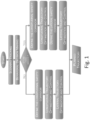
- Figure 1 depicts a flow chart describing the intellectual process that is implemented when a user drives a car on an highway.
- a scenario tracking activity where the driver observes all the potential obstacles in vehicle surroundings. Based on the situation, a decision will be taken: to stay in the same lane or to implement a lane change manoeuvre.
- the driver has to define a longitudinal safety corridor: if the vehicle remains in the same lane, the space ahead the vehicle is observed until the first obstacle on the same lane. Otherwise, in case of a lane change manoeuvre, the longitudinal safety corridor is the longitudinal free space ahead the vehicle during lane change.
- the driver after having made the mentioned considerations on longitudinal speed, defines also how to approach the lateral planning. This is done by defining the lateral safety corridor during the manoeuvre, optimizing the lateral trajectory in coherence with longitudinal behaviour planned in previous step.
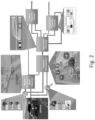
- Figure 2 shows a block diagram of an implementation of this intellectual process by an automotive electronic dynamics control system, referenced as a whole with reference numeral 1 of an automated motor-vehicle, hereinafter referred to as ego motor-vehicle and referenced as a whole with reference numeral 2.
- Figure 2 shows the flow of measured information on a real vehicle is translated into longitudinal and lateral planned trajectories.
- the proposed algorithm uses traditional active chassis sensors, such as wheel speed sensors, steering wheel sensor, and inertial measurement unit as well as ADAS surroundings sensors such as forward looking camera and medium range front/comer radars.
- the main phases described in the previous paragraph are mapped on the depicted blocks, for example the scenario tracking activity is implemented by the blocks labelled 'Vehicle & Obstacle State Observer' and ⁇ Scenario Reconstructor' and referenced with reference numerals 3 and 4.
- the block labelled 'Behavioural Planner' and referenced with reference numeral 5 implements and defines the decision making about remaining in the same lane or starting a lane change, while longitudinal/lateral safety corridors and all the main constrains for the non-linear optimizations are included in the blocks labelled 'Longitudinal Trajectory Planner' and 'Lateral Trajectory Planner' and referenced with reference numerals 6 and 7.
- the receding horizon control theory is used in a wide and commonly acknowledged way.
- the main advantages of this control theory are related to the possibility to use a physical model and related constraints for the optimization.
- This theory is a natural evolution of state feedback optimal control that has as basic requirement the closed loop stability.
- it's possible to use the model to calculate the effect of a sequence of commands on the plant and to minimize the tracking error of low level controls by applying only the first sample of planned vector of commands.
- the computational effort required for not trivial optimization problems is significant. And this is one of the reasons that lead to implement two different optimization problems based on linear longitudinal and lateral dynamics models.
- Figure 3 shows the same block diagram as the one shown in Figure 2 , but with additional details of the vehicle reference system, the road reference system, and the physical quantities involved, where: Name Unit Description ⁇ rad/s Vehicle yaw rate a x m/s 2 Vehicle longitudinal acceleration V x m/s Vehicle longitudinal speed a y m/s 2 Vehicle lateral acceleration s m Displacement along curvilinear axis Y lat m Lateral displacement ⁇ wheel rad/s Wheel spin speed ⁇ sw rad Steering wheel angle
- Filtered and indirect measured signals are fundamental for the Scenario Reconstructor 4 and the Behavioral Planner 5.
- Ego motor-vehicle states are mainly useful for the lateral trajectory optimization problem, where it's fundamental to measure vehicle lateral states to consider vehicle model in order to preserve vehicle stability. Obstacle states are used mainly in the Behavioral Planner 5 where filtered/reconstructed signals are starting point of decision scenario preview.
- the ego motor-vehicle state observer is synthetized according to vehicle Kalman observer even designed in [22].
- the state observer provides camera filtered measurements: yaw rate ( ⁇ ), heading angle ( ⁇ ), and lateral displacement ( Y lat ). Moreover, it reconstructs the lateral vehicle speed ( V y ), giving all the information that the controller needs.
- a similar approach is used to filter and to reconstruct the states related to the longitudinal movements of obstacles.
- Each obstacle is modelled as a material point that moves with constant acceleration.
- the use of a constant acceleration model is a good tradeoff between complexity and prediction accuracy considering also measurement reliability of ADAS sensors.
- Vehicle Longitudinal and Lateral dynamics are managed with two different Trajectory Planners: the Longitudinal Trajectory Planner 7, which is designed to compute a planned longitudinal trajectory, and the Longitudinal Trajectory Planner 6, which is designed to compute a planned lateral trajectory, and where the planned longitudinal trajectory is computed before the planned lateral trajectory.
- the Longitudinal Trajectory Planner 7 which is designed to compute a planned longitudinal trajectory
- the Longitudinal Trajectory Planner 6 which is designed to compute a planned lateral trajectory, and where the planned longitudinal trajectory is computed before the planned lateral trajectory.
- a real-time, non-linear convex optimization problem [20] is solved on a finite horizon based on:
- the longitudinal dynamics of the ego motor-vehicle 2 is modeled by a simple double integrator in discrete time (k is the sample time).
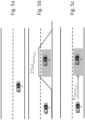
- Figure 4 schematically shows the optimization safe corridor and the single track model used in the MPC formulation [19].
- TTC time-to-collision
- Figure 7 schematically shows the free corridor definition for 4) condition (a, b).
- the trajectory planning of the present invention has been simulated and experimentally validated via simulation by using IPG Car-Maker in a Matlab/Simulink environment. Afterwards, only part of simulation scenarios has been evaluated on a Fiat 500X equipped with a dSPACE MicroAutobox II.
- the dotted line limits the 'Danger Zone' that the ego motor-vehicle 2 must avoid (i.e., a fixed shape around obstacle according to its type).
- the continuous line defines the constrain used for MPC optimization (longitudinal and lateral) (i.e., a fixed distance to ⁇ Danger Zone' and inside 'Safe Corridor' that is calculated as half of vehicle track / wheelbase + additional space tolerance).
- Scenarios are defined as follows, where presented contents are allocated on different driving conditions: Scenario description Behavioral Planning Trajectory Planning Lateral Planning Longitudinal Planning Tracking an obstacle ⁇ ⁇ ⁇ Overtaking an obstacle ⁇ ⁇ ⁇ Overtake Evaluation with respect to an incoming obstacle on the left lane ⁇ ⁇ ⁇ General and more complex scenario ⁇ ⁇ ⁇
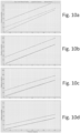
- FIG. 10a,b,c,d The plot of the first simulation scenario, where the planned position on road of an ego motor-vehicle that tracks a decelerating leader vehicle ( Figures 10a,b,c,d ) is depicted, foresees that the ego motor-vehicle (80 km/h) engages the leader vehicle (initial speed 70 km/h) ( Figures 10a-b ), that, subsequently, decides to decelerate to 40 km/h, so the ego motor-vehicle decelerates to leader vehicle speed ( Figures 10c-d).
- Figures 10a,b,c,d depict the sequence of planned longitudinal trajectory with a time step of 100ms and prediction steps 45 (Np). The chosen prediction steps is enough to represent a quasi-infinite horizon for longitudinal dynamics optimization (about 125 meters at 100 km/h).
- the plot in Figure 12 shows an ego motor-vehicle with cruise speed of 90 km/h that engages a leader motor-vehicle with cruise speed of 60 km/h, then an incoming vehicle supervenes on the left lane, the ego motor-vehicle evaluates the time to collision before enabling the overtake and starting the maneuver.
- the plot in Figure 12 also shows a space-based planned position of the ego motor-vehicle, while the depth of car boundaries shows the same time stamp of different motor-vehicles.
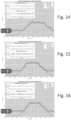
- the present invention has been validated on an FCA test track with an ego motor-vehicle and a cooperative leader motor-vehicle, and the previously presented 'overtaking an obstacle' scenario has been selected as reference test.
- the validation test has been setup in a straight road with three lanes. Each lane width is 3.7m, the straight length is 1.3 km.
- the graphs shown in Figures 14, 15, 16 show an example (ego motor-vehicle speed 70 km/h, leader vehicle speed 60 km/h) of real controlled motor-vehicle results on test track, the red line is the MPC constraint used for the optimization.
- the red rectangle is the space where ego motor-vehicle and leader motor-vehicle are placed side by side.
- low actuator controls steering wheel position ([21]) and longitudinal speed
- the actuation loops (10 ms of sampling time) were faster than MPC planners/controllers (lateral and longitudinal).
- the white graph are reported the family of curves generated by lateral MPC with an execution sampling time of 50ms.
- the last detail is that the oscillations on planned and executed trajectories are due to sketchy steering position control loop tuning available on prototypal motor-vehicle.
- the present invention foresees vehicle dynamics and guarantees the dynamical feasibility of the planned trajectory by a model-based prediction of the motor-vehicle's motion.
Landscapes
- Engineering & Computer Science (AREA)
- Automation & Control Theory (AREA)
- Transportation (AREA)
- Mechanical Engineering (AREA)
- Human Computer Interaction (AREA)
- Traffic Control Systems (AREA)
Claims (4)
- Elektronisches System (1) zum Steuern von Fahrzeugdynamik für ein automatisiertes Kraftfahrzeug (2),wobei das elektronische System (1) zum Steuern von Fahrzeugdynamik zwei getrennte Bewegungsbahnplaner auf MPC-(Model-Predictive-Control-)Basis umfasst, die Folgendes umfassen:- einen Planer (6) für eine Bewegungsbahn in Längsrichtung, der dafür ausgestaltet ist, eine geplante Bewegungsbahn in Längsrichtung für das automatisierte Kraftfahrzeug (2) zu berechnen, und- einen Planer (7) für eine seitliche Bewegungsbahn, der dafür ausgestaltet ist, eine geplante Bewegungsbahn in seitlicher Richtung für das automatisierte Kraftfahrzeug (2) zu berechnen,wobei das elektronische System (1) zum Steuern von Fahrzeugdynamik ferner dafür ausgestaltet ist, zu veranlassen, dass die geplante Bewegungsbahn in Längsrichtung vor der geplanten Bewegungsbahn in seitlicher Richtung berechnet wird,wobei das elektronische System (1) zum Steuern von Fahrzeugdynamik ferner dafür ausgestaltet ist, Folgendes zu implementieren:- eine Beobachtungseinrichtung (3) für Fahrzeug- und Hinderniszustände, die dafür ausgestaltet ist, beobachtete Fahrzeuggrößen zu berechnen, die es ermöglichen, potentielle Hindernisse in der Umgebung des automatisierten Kraftfahrzeugs (2) zu identifizieren und nachzuverfolgen,- eine Einrichtung zur Rekonstruktion von Szenarien (4), die dafür ausgestaltet ist, potentielle Hindernisse in der Umgebung des automatisierten Kraftfahrzeugs (2) basierend auf den beobachteten Fahrzeuggrößen, berechnet von der Beobachtungseinrichtung (3) für Fahrzeug- und Hinderniszustände zu identifizieren und nachzuverfolgen, und- einen Verhaltensplaner (5), der dafür ausgestaltet ist, basierend auf den potentiellen Hindernissen in der Umgebung des automatisierten Kraftfahrzeugs (2) zu entscheiden, ob eine Fahrspur, die gegenwärtig von dem automatisierten Kraftfahrzeug (2) befahren wird, zu halten ist oder ob ein Spurwechselmanöver auszuführen ist, und entsprechende Einschränkungen und Bezugswerte für die Planer (6, 7) der Bewegungsbahnen in Längs- oder Seitenrichtung zu berechnen,dadurch gekennzeichnet, dass die Beobachtungseinrichtung (3) für Fahrzeug- und Hinderniszustände dafür ausgestaltet ist, Fahrzeuggrößen zu empfangen, die von einem Fahrzeugsensorsystem des automatisierten Kraftfahrzeugs (2) gemessen werden, und/oder Fahrzeuggrößen, die basierend auf gemessenen Fahrzeuggrößen berechnet werden, und dafür, die beobachteten Fahrzeuggrößen basierend auf den empfangenen gemessenen/berechneten Fahrzeuggrößen zu berechnen,die gemessenen/berechneten Fahrzeuggrößen Straßenkrümmung (ρ), Kraftfahrzeugkurs (ε) und seitliche Position (γ), die eine gegenwärtige Fahrroute des automatisierten Kraftfahrzeugs (2) angeben, eine Giergeschwindigkeit (ψ̇ ) des Kraftfahrzeugs und eine Längs- und Seitenbeschleunigung (ẍ, γ̈), eine Raddrehzahl (ωwheel) und einen Lenkwinkel und eine Lenkgeschwindigkeit (δsw, δ̇sw ) umfassen, die einen dynamischen Zustand des automatisierten Kraftfahrzeugs (2) und eine Hindernisposition und Dynamiken in Längsrichtung von potentiellen Hindernissen in der Umgebung des automatisierten Kraftfahrzeugs (2) angeben,die beobachteten Fahrzeuggrößen Straßenkrümmung (ρ̃), Kraftfahrzeugkurs (∈̃) und seitliche Position (γ̃), die eine beobachtete Fahrroute des automatisierten Kraftfahrzeugs (2) angeben, eine Giergeschwindigkeit () und eine seitliche Geschwindigkeit (Ṽ γ) sowie Positionen in Längsrichtung, Geschwindigkeiten und Beschleunigungen von Hindernissen (x̃,
 ,
, ) umfassen,
 die Einrichtung zur Rekonstruktion von Szenarien (4) dafür ausgestaltet ist, potentielle Hindernisse in der Umgebung des automatisierten Kraftfahrzeugs (2) basierend auf den gemessenen/berechneten Fahrzeuggrößen und den beobachteten Fahrzeuggrößen zu identifizieren und nachzuverfolgen,der Verhaltensplaner (5) dafür ausgestaltet ist, von der Einrichtung zur Rekonstruktion von Szenarien (4) Daten zu empfangen, welche die potentiellen Hindernisse in der Umgebung des automatisierten Kraftfahrzeugs (2) darstellen, und von dem Planer (6) für eine Bewegungsbahn in Längsrichtung eine oder mehrere Größen, die eine geplante Bewegungsbahn in Längsrichtung darstellen, und Einschränkungen in Längsrichtung und seitliche Richtung sowie Referenzpositionen in Längsrichtung und seitliche Richtung (xref, γref) für das automatisierte Kraftfahrzeug (2) zu berechnen,der Planer (7) für eine seitliche Bewegungsbahn dafür ausgestaltet ist, von dem Verhaltensplaner (5) die seitlichen Einschränkungen und die seitliche Referenzposition (γref) für das automatisierte Kraftfahrzeug (2) zu empfangen und Größen zu berechnen, die eine geplante seitliche Bewegungsbahn darstellen und eine seitliche Position und Geschwindigkeit (γ, Vγ), einen Kurs (ε), eine Giergeschwindigkeit (ψ̇) und einen Lenkwinkel (δ) umfassen,der Planer (6) für eine Bewegungsbahn in Längsrichtung dafür ausgestaltet ist, von dem Verhaltensplaner (5) die Einschränkungen in Längsrichtung und die Referenzposition in Längsrichtung (xref) für das automatisierte Kraftfahrzeug (2) zu empfangen und Größen zu berechnen, die eine geplante Bewegungsbahn in Längsrichtung darstellen und eine Position in Längsrichtung, Geschwindigkeit und Beschleunigung (s, ṡ, s̈) des Fahrzeugs umfassen.
 - Elektronisches System (1) zum Steuern von Fahrzeugdynamik nach Anspruch 1, wobei der Verhaltensplaner (5) dafür ausgestaltet ist, basierend auf Zeit-bis-Kollision (TTC - Time-To-Collision) des automatisierten Kraftfahrzeugs (2) mit dem potentiellen Hindernis in der Umgebung des automatisierten Kraftfahrzeugs (2) Einschränkungen für die Planer (6, 7) für eine Bewegungsbahn in Längsrichtung und für eine seitliche Bewegungsbahn zu berechnen.
- Elektronisches System (1) zum Steuern von Fahrzeugdynamik nach Anspruch 2, wobei der Verhaltensplaner (5) dafür ausgestaltet ist, verschiedene Einschränkungen für die Planer (6, 7) für eine Bewegungsbahn in Längsrichtung und für eine seitliche Bewegungsbahn wie folgt zu berechnen:- wenn keine Hindernisse erkannt werden, umfassen die Einschränkungen nur Fahrspurbegrenzungen,- wenn nur ein Hindernis vor dem automatisierten Kraftfahrzeug (2) erkannt wird, können abhängig von der relativen Geschwindigkeit zwei Fälle eintreten:∘ Überholanfrage: die seitliche Einschränkung wird modifiziert, um es dem automatisierten Kraftfahrzeug (2) zu ermöglichen, das Manöver durchzuführen, während keine Einschränkungen in Längsrichtung bezüglich des vorausfahrenden Hindernisses berechnet werden,∘ Nachverfolgungsanfrage: eine Einschränkung in Längsrichtung wird berechnet, seitliche Einschränkungen halten nach wie vor die Fahrspurbegrenzungen ein,- wenn sich auf der Überholspur ein näherkommendes Hindernis befindet, zusammen mit einem langsameren Kraftfahrzeug vor dem automatisierten Kraftfahrzeug (2), wird die Zeit-bis-Kollision (TTC) relativ zu dem näherkommenden Hindernis berechnet, um zu bestimmen, ob eine Kollision des automatisierten Kraftfahrzeugs (2) mit dem näherkommenden Hindernis auftreten kann:∘ wenn keine Kollision bestimmt wird: Überholanfrage, die seitliche Einschränkung wird modifiziert,∘ wenn eine Kollision bestimmt wird: Nachverfolgungsanfrage, eine Einschränkung in Längsrichtung wird berechnet, und- sobald ein Überholvorgang gestartet wurde, wird, wenn ein anderes Hindernis in der Überholspur erkannt wird, das Hindernis auf der Überholspur nachverfolgt, um den Sicherheitsabstand zu halten.
- Software, die in eine elektronische Fahrzeugsteuereinheit ladbar ist und dafür ausgestaltet ist, bei ihrer Ausführung die Konfigurierung der elektronischen Fahrzeugsteuereinheit zu veranlassen, um das elektronische System (1) zum Steuern von Fahrzeugdynamik nach einem der vorhergehenden Ansprüche zu implementieren.
Applications Claiming Priority (3)
| Application Number | Priority Date | Filing Date | Title |
|---|---|---|---|
| EP19198133 | 2019-09-18 | ||
| IT102020000009259A IT202000009259A1 (it) | 2019-09-18 | 2020-04-28 | Progettazione basata su modello della pianificazione e del controllo della traiettoria per autoveicoli automatizzati in un ambiente dinamico |
| PCT/IB2020/058721 WO2021053607A1 (en) | 2019-09-18 | 2020-09-18 | Model-based design of trajectory planning and control for automated motor-vehicles in a dynamic environment |
Publications (2)
| Publication Number | Publication Date |
|---|---|
| EP4031428A1 EP4031428A1 (de) | 2022-07-27 |
| EP4031428B1 true EP4031428B1 (de) | 2024-11-13 |
Family
ID=72603500
Family Applications (1)
| Application Number | Title | Priority Date | Filing Date |
|---|---|---|---|
| EP20775727.9A Active EP4031428B1 (de) | 2019-09-18 | 2020-09-18 | Modellbasierter entwurf einer trajektorienplanung und -steuerung für automatisierte kraftfahrzeuge in einer dynamischen umgebung |
Country Status (3)
| Country | Link |
|---|---|
| US (1) | US20220371594A1 (de) |
| EP (1) | EP4031428B1 (de) |
| WO (1) | WO2021053607A1 (de) |
Families Citing this family (20)
| Publication number | Priority date | Publication date | Assignee | Title |
|---|---|---|---|---|
| US12291233B2 (en) * | 2019-09-27 | 2025-05-06 | Honda Motor Co., Ltd. | System and method for providing accurate trajectory following for automated vehicles in dynamic environments |
| EP4081876B1 (de) | 2020-01-28 | 2024-04-10 | Five AI Limited | Planung bei mobilen robotern |
| EP4078320B1 (de) | 2020-01-28 | 2024-08-14 | Five AI Limited | Planung in mobilen robotern |
| CN111780981B (zh) * | 2020-05-21 | 2022-02-18 | 东南大学 | 一种智能车辆编队变道性能测评方法 |
| KR20220056923A (ko) * | 2020-10-28 | 2022-05-09 | 현대자동차주식회사 | 자율주행 제어 장치 및 방법 |
| US12576864B2 (en) * | 2020-10-30 | 2026-03-17 | Five AI Limited | Tools for performance testing and/or training autonomous vehicle planners |
| CN112937608B (zh) * | 2021-03-31 | 2022-06-21 | 吉林大学 | 一种基于轨迹预测的冰雪环境无人驾驶车辆一体化滚动决策方法、装置及存储介质 |
| FR3121411B1 (fr) * | 2021-04-06 | 2023-10-27 | Renault Sas | Procédé de commande de trajectoire de changement de voie pour véhicule autonome. |
| CN113296509B (zh) * | 2021-05-21 | 2022-11-08 | 上海海事大学 | 一种用于无人表面船的自主轨迹追踪融合控制方法 |
| CN113298473A (zh) * | 2021-06-11 | 2021-08-24 | 四川铁公铁信息技术有限公司 | 一种园区货物运输路线规划系统及方法 |
| CN114115234B (zh) * | 2021-10-28 | 2024-11-29 | 江苏大学 | 一种基于监控策略的无人车换道路径规划方法 |
| CN114248911B (zh) * | 2021-12-24 | 2024-03-01 | 兰州飞行控制有限责任公司 | 一种直升机电动串联舵机控制信号调整方法 |
| CN114475607B (zh) * | 2022-04-13 | 2022-07-12 | 清华大学 | 自动驾驶车辆的拟人化换道方法、装置、车辆及存储介质 |
| CN114750750B (zh) * | 2022-04-28 | 2024-09-20 | 南阳理工学院 | 一种自动泊车的最优跟踪控制方法、系统、设备和介质 |
| CN115079699B (zh) * | 2022-06-30 | 2025-01-17 | 北京理工大学 | 一种基于模型预测控制的人机共驾汽车的运动规划方法 |
| CN116224997A (zh) * | 2022-12-30 | 2023-06-06 | 新石器慧通(北京)科技有限公司 | 轨迹规划方法和装置、电子设备和存储介质 |
| CN116822204B (zh) * | 2023-06-27 | 2025-06-17 | 襄阳达安汽车检测中心有限公司 | 车辆功能测试中危险场景的自动生成方法、装置和设备 |
| CN117742316B (zh) * | 2023-11-28 | 2024-08-02 | 上海友道智途科技有限公司 | 一种基于带挂车模型的最优轨迹规划方法 |
| CN118597119B (zh) * | 2024-07-02 | 2025-10-03 | 江苏大学 | 一种考虑碰撞时间的自动紧急转向路径规划方法及系统 |
| CN119502947B (zh) * | 2024-12-02 | 2026-01-20 | 西北工业大学 | 基于模糊模型预测控制的自动驾驶汽车避碰方法 |
Family Cites Families (2)
| Publication number | Priority date | Publication date | Assignee | Title |
|---|---|---|---|---|
| KR101480652B1 (ko) * | 2013-12-11 | 2015-01-09 | 현대자동차주식회사 | 차선 변경 제어 장치 및 그 변경 제어 방법 |
| US10725470B2 (en) * | 2017-06-13 | 2020-07-28 | GM Global Technology Operations LLC | Autonomous vehicle driving systems and methods for critical conditions |
-
2020
- 2020-09-18 EP EP20775727.9A patent/EP4031428B1/de active Active
- 2020-09-18 WO PCT/IB2020/058721 patent/WO2021053607A1/en not_active Ceased
- 2020-09-18 US US17/627,005 patent/US20220371594A1/en not_active Abandoned
Also Published As
| Publication number | Publication date |
|---|---|
| US20220371594A1 (en) | 2022-11-24 |
| WO2021053607A1 (en) | 2021-03-25 |
| EP4031428A1 (de) | 2022-07-27 |
Similar Documents
| Publication | Publication Date | Title |
|---|---|---|
| EP4031428B1 (de) | Modellbasierter entwurf einer trajektorienplanung und -steuerung für automatisierte kraftfahrzeuge in einer dynamischen umgebung | |
| You et al. | Autonomous planning and control for intelligent vehicles in traffic | |
| DE102019102944B4 (de) | Systeme und Verfahren für eine Fahrzeugregelstrategie mit niedrigem Vorsteuerungsniveau | |
| Cao et al. | An optimal hierarchical framework of the trajectory following by convex optimisation for highly automated driving vehicles | |
| EP4048567B1 (de) | Trajektorienplanung für kraftfahrzeug und steuerung zur veranlassung von automatisierten motorfahrzeugen zur durchführung von fahrmanövern mit niedriger geschwindigkeit im automatisierten fahrbetrieb | |
| Lima et al. | Spatial model predictive control for smooth and accurate steering of an autonomous truck | |
| Zhang et al. | Dynamic trajectory planning for vehicle autonomous driving | |
| DE102018113926A1 (de) | Autonome Fahrzeugantriebssysteme und Verfahren für kritische Zustände | |
| DE102016100102B4 (de) | Verfahren und system zur automatischen kollisionsvermeidung | |
| DE102017201569A1 (de) | Vorschau der lateralen steuerung für das automatisierte fahren | |
| Sun et al. | An active safety control method of collision avoidance for intelligent connected vehicle based on driving risk perception | |
| Chiang et al. | Embedded driver-assistance system using multiple sensors for safe overtaking maneuver | |
| Claussmann et al. | A path planner for autonomous driving on highways using a human mimicry approach with binary decision diagrams | |
| Yuan et al. | Mixed local motion planning and tracking control framework for autonomous vehicles based on model predictive control | |
| DE102022116418A1 (de) | Maschinensteuerung | |
| Gong et al. | Game theory-based decision-making and iterative predictive lateral control for cooperative obstacle avoidance of guided vehicle platoon | |
| Gutjahr et al. | Automatic collision avoidance during parking and maneuvering—An optimal control approach | |
| Yue et al. | Automated hazard escaping trajectory planning/tracking control framework for vehicles subject to tire blowout on expressway | |
| Nilsson et al. | Automated highway lane changes of long vehicle combinations: A specific comparison between driver model based control and non-linear model predictive control | |
| Nilsson et al. | Driver model based automated driving of long vehicle combinations in emulated highway traffic | |
| Wang et al. | Hierarchical CNNPID based active steering control method for intelligent vehicle facing emergency lane-changing | |
| Duan et al. | Implementing trajectory tracking control algorithm for autonomous vehicles | |
| Zhang et al. | Design and application of automatic driving emergency collision avoidance control algorithm based on artificial intelligence technology | |
| Balachandran et al. | Creating predictive haptic feedback for obstacle avoidance using a model predictive control (MPC) framework | |
| Nordell | Trajectory planning for autonomous vehicles and cooperative driving |
Legal Events
| Date | Code | Title | Description |
|---|---|---|---|
| STAA | Information on the status of an ep patent application or granted ep patent |
Free format text: STATUS: UNKNOWN |
|
| STAA | Information on the status of an ep patent application or granted ep patent |
Free format text: STATUS: THE INTERNATIONAL PUBLICATION HAS BEEN MADE |
|
| PUAI | Public reference made under article 153(3) epc to a published international application that has entered the european phase |
Free format text: ORIGINAL CODE: 0009012 |
|
| STAA | Information on the status of an ep patent application or granted ep patent |
Free format text: STATUS: REQUEST FOR EXAMINATION WAS MADE |
|
| 17P | Request for examination filed |
Effective date: 20220125 |
|
| AK | Designated contracting states |
Kind code of ref document: A1 Designated state(s): AL AT BE BG CH CY CZ DE DK EE ES FI FR GB GR HR HU IE IS IT LI LT LU LV MC MK MT NL NO PL PT RO RS SE SI SK SM TR |
|
| DAV | Request for validation of the european patent (deleted) | ||
| DAX | Request for extension of the european patent (deleted) | ||
| GRAP | Despatch of communication of intention to grant a patent |
Free format text: ORIGINAL CODE: EPIDOSNIGR1 |
|
| STAA | Information on the status of an ep patent application or granted ep patent |
Free format text: STATUS: GRANT OF PATENT IS INTENDED |
|
| RIC1 | Information provided on ipc code assigned before grant |
Ipc: B60W 60/00 20200101ALI20240508BHEP Ipc: B60W 30/18 20120101AFI20240508BHEP |
|
| INTG | Intention to grant announced |
Effective date: 20240612 |
|
| GRAS | Grant fee paid |
Free format text: ORIGINAL CODE: EPIDOSNIGR3 |
|
| GRAA | (expected) grant |
Free format text: ORIGINAL CODE: 0009210 |
|
| STAA | Information on the status of an ep patent application or granted ep patent |
Free format text: STATUS: THE PATENT HAS BEEN GRANTED |
|
| AK | Designated contracting states |
Kind code of ref document: B1 Designated state(s): AL AT BE BG CH CY CZ DE DK EE ES FI FR GB GR HR HU IE IS IT LI LT LU LV MC MK MT NL NO PL PT RO RS SE SI SK SM TR |
|
| REG | Reference to a national code |
Ref country code: GB Ref legal event code: FG4D |
|
| REG | Reference to a national code |
Ref country code: CH Ref legal event code: EP |
|
| REG | Reference to a national code |
Ref country code: DE Ref legal event code: R096 Ref document number: 602020041361 Country of ref document: DE |
|
| REG | Reference to a national code |
Ref country code: IE Ref legal event code: FG4D |
|
| REG | Reference to a national code |
Ref country code: LT Ref legal event code: MG9D |
|
| REG | Reference to a national code |
Ref country code: NL Ref legal event code: MP Effective date: 20241113 |
|
| PG25 | Lapsed in a contracting state [announced via postgrant information from national office to epo] |
Ref country code: IS Free format text: LAPSE BECAUSE OF FAILURE TO SUBMIT A TRANSLATION OF THE DESCRIPTION OR TO PAY THE FEE WITHIN THE PRESCRIBED TIME-LIMIT Effective date: 20250313 Ref country code: PT Free format text: LAPSE BECAUSE OF FAILURE TO SUBMIT A TRANSLATION OF THE DESCRIPTION OR TO PAY THE FEE WITHIN THE PRESCRIBED TIME-LIMIT Effective date: 20250313 Ref country code: HR Free format text: LAPSE BECAUSE OF FAILURE TO SUBMIT A TRANSLATION OF THE DESCRIPTION OR TO PAY THE FEE WITHIN THE PRESCRIBED TIME-LIMIT Effective date: 20241113 |
|
| PG25 | Lapsed in a contracting state [announced via postgrant information from national office to epo] |
Ref country code: FI Free format text: LAPSE BECAUSE OF FAILURE TO SUBMIT A TRANSLATION OF THE DESCRIPTION OR TO PAY THE FEE WITHIN THE PRESCRIBED TIME-LIMIT Effective date: 20241113 Ref country code: NL Free format text: LAPSE BECAUSE OF FAILURE TO SUBMIT A TRANSLATION OF THE DESCRIPTION OR TO PAY THE FEE WITHIN THE PRESCRIBED TIME-LIMIT Effective date: 20241113 |
|
| REG | Reference to a national code |
Ref country code: AT Ref legal event code: MK05 Ref document number: 1741473 Country of ref document: AT Kind code of ref document: T Effective date: 20241113 |
|
| PG25 | Lapsed in a contracting state [announced via postgrant information from national office to epo] |
Ref country code: BG Free format text: LAPSE BECAUSE OF FAILURE TO SUBMIT A TRANSLATION OF THE DESCRIPTION OR TO PAY THE FEE WITHIN THE PRESCRIBED TIME-LIMIT Effective date: 20241113 |
|
| PG25 | Lapsed in a contracting state [announced via postgrant information from national office to epo] |
Ref country code: ES Free format text: LAPSE BECAUSE OF FAILURE TO SUBMIT A TRANSLATION OF THE DESCRIPTION OR TO PAY THE FEE WITHIN THE PRESCRIBED TIME-LIMIT Effective date: 20241113 |
|
| PG25 | Lapsed in a contracting state [announced via postgrant information from national office to epo] |
Ref country code: NO Free format text: LAPSE BECAUSE OF FAILURE TO SUBMIT A TRANSLATION OF THE DESCRIPTION OR TO PAY THE FEE WITHIN THE PRESCRIBED TIME-LIMIT Effective date: 20250213 |
|
| PG25 | Lapsed in a contracting state [announced via postgrant information from national office to epo] |
Ref country code: LV Free format text: LAPSE BECAUSE OF FAILURE TO SUBMIT A TRANSLATION OF THE DESCRIPTION OR TO PAY THE FEE WITHIN THE PRESCRIBED TIME-LIMIT Effective date: 20241113 Ref country code: AT Free format text: LAPSE BECAUSE OF FAILURE TO SUBMIT A TRANSLATION OF THE DESCRIPTION OR TO PAY THE FEE WITHIN THE PRESCRIBED TIME-LIMIT Effective date: 20241113 Ref country code: GR Free format text: LAPSE BECAUSE OF FAILURE TO SUBMIT A TRANSLATION OF THE DESCRIPTION OR TO PAY THE FEE WITHIN THE PRESCRIBED TIME-LIMIT Effective date: 20250214 |
|
| PG25 | Lapsed in a contracting state [announced via postgrant information from national office to epo] |
Ref country code: PL Free format text: LAPSE BECAUSE OF FAILURE TO SUBMIT A TRANSLATION OF THE DESCRIPTION OR TO PAY THE FEE WITHIN THE PRESCRIBED TIME-LIMIT Effective date: 20241113 |
|
| PG25 | Lapsed in a contracting state [announced via postgrant information from national office to epo] |
Ref country code: RS Free format text: LAPSE BECAUSE OF FAILURE TO SUBMIT A TRANSLATION OF THE DESCRIPTION OR TO PAY THE FEE WITHIN THE PRESCRIBED TIME-LIMIT Effective date: 20250213 |
|
| PG25 | Lapsed in a contracting state [announced via postgrant information from national office to epo] |
Ref country code: SM Free format text: LAPSE BECAUSE OF FAILURE TO SUBMIT A TRANSLATION OF THE DESCRIPTION OR TO PAY THE FEE WITHIN THE PRESCRIBED TIME-LIMIT Effective date: 20241113 |
|
| PG25 | Lapsed in a contracting state [announced via postgrant information from national office to epo] |
Ref country code: DK Free format text: LAPSE BECAUSE OF FAILURE TO SUBMIT A TRANSLATION OF THE DESCRIPTION OR TO PAY THE FEE WITHIN THE PRESCRIBED TIME-LIMIT Effective date: 20241113 |
|
| PG25 | Lapsed in a contracting state [announced via postgrant information from national office to epo] |
Ref country code: EE Free format text: LAPSE BECAUSE OF FAILURE TO SUBMIT A TRANSLATION OF THE DESCRIPTION OR TO PAY THE FEE WITHIN THE PRESCRIBED TIME-LIMIT Effective date: 20241113 |
|
| PG25 | Lapsed in a contracting state [announced via postgrant information from national office to epo] |
Ref country code: RO Free format text: LAPSE BECAUSE OF FAILURE TO SUBMIT A TRANSLATION OF THE DESCRIPTION OR TO PAY THE FEE WITHIN THE PRESCRIBED TIME-LIMIT Effective date: 20241113 |
|
| PG25 | Lapsed in a contracting state [announced via postgrant information from national office to epo] |
Ref country code: SK Free format text: LAPSE BECAUSE OF FAILURE TO SUBMIT A TRANSLATION OF THE DESCRIPTION OR TO PAY THE FEE WITHIN THE PRESCRIBED TIME-LIMIT Effective date: 20241113 |
|
| PG25 | Lapsed in a contracting state [announced via postgrant information from national office to epo] |
Ref country code: CZ Free format text: LAPSE BECAUSE OF FAILURE TO SUBMIT A TRANSLATION OF THE DESCRIPTION OR TO PAY THE FEE WITHIN THE PRESCRIBED TIME-LIMIT Effective date: 20241113 |
|
| REG | Reference to a national code |
Ref country code: DE Ref legal event code: R097 Ref document number: 602020041361 Country of ref document: DE |
|
| PG25 | Lapsed in a contracting state [announced via postgrant information from national office to epo] |
Ref country code: SE Free format text: LAPSE BECAUSE OF FAILURE TO SUBMIT A TRANSLATION OF THE DESCRIPTION OR TO PAY THE FEE WITHIN THE PRESCRIBED TIME-LIMIT Effective date: 20241113 |
|
| PLBE | No opposition filed within time limit |
Free format text: ORIGINAL CODE: 0009261 |
|
| STAA | Information on the status of an ep patent application or granted ep patent |
Free format text: STATUS: NO OPPOSITION FILED WITHIN TIME LIMIT |
|
| PGFP | Annual fee paid to national office [announced via postgrant information from national office to epo] |
Ref country code: DE Payment date: 20250820 Year of fee payment: 6 |
|
| PGFP | Annual fee paid to national office [announced via postgrant information from national office to epo] |
Ref country code: IT Payment date: 20250820 Year of fee payment: 6 |
|
| PGFP | Annual fee paid to national office [announced via postgrant information from national office to epo] |
Ref country code: FR Payment date: 20250820 Year of fee payment: 6 |
|
| 26N | No opposition filed |
Effective date: 20250814 |