EP4048558B1 - Reinigungseinheit, optische abtastvorrichtung und verfahren zum reinigen - Google Patents
Reinigungseinheit, optische abtastvorrichtung und verfahren zum reinigen Download PDFInfo
- Publication number
- EP4048558B1 EP4048558B1 EP20803292.0A EP20803292A EP4048558B1 EP 4048558 B1 EP4048558 B1 EP 4048558B1 EP 20803292 A EP20803292 A EP 20803292A EP 4048558 B1 EP4048558 B1 EP 4048558B1
- Authority
- EP
- European Patent Office
- Prior art keywords
- wiper blade
- scraper
- cleaning unit
- wipe
- window pane
- Prior art date
- Legal status (The legal status is an assumption and is not a legal conclusion. Google has not performed a legal analysis and makes no representation as to the accuracy of the status listed.)
- Active
Links
Images


Classifications
-
- B—PERFORMING OPERATIONS; TRANSPORTING
- B60—VEHICLES IN GENERAL
- B60S—SERVICING, CLEANING, REPAIRING, SUPPORTING, LIFTING, OR MANOEUVRING OF VEHICLES, NOT OTHERWISE PROVIDED FOR
- B60S1/00—Cleaning of vehicles
- B60S1/02—Cleaning windscreens, windows or optical devices
- B60S1/04—Wipers or the like, e.g. scrapers
- B60S1/0475—Cleaning of wiper blades
- B60S1/0477—Arrangement for deicing or for removing debris from wiper blades
-
- B—PERFORMING OPERATIONS; TRANSPORTING
- B60—VEHICLES IN GENERAL
- B60S—SERVICING, CLEANING, REPAIRING, SUPPORTING, LIFTING, OR MANOEUVRING OF VEHICLES, NOT OTHERWISE PROVIDED FOR
- B60S1/00—Cleaning of vehicles
- B60S1/02—Cleaning windscreens, windows or optical devices
- B60S1/04—Wipers or the like, e.g. scrapers
- B60S1/0475—Cleaning of wiper blades
- B60S1/0486—Cleaning of wiper blades the cleaning device being integrated with the vehicle
-
- B—PERFORMING OPERATIONS; TRANSPORTING
- B60—VEHICLES IN GENERAL
- B60S—SERVICING, CLEANING, REPAIRING, SUPPORTING, LIFTING, OR MANOEUVRING OF VEHICLES, NOT OTHERWISE PROVIDED FOR
- B60S1/00—Cleaning of vehicles
- B60S1/02—Cleaning windscreens, windows or optical devices
- B60S1/56—Cleaning windscreens, windows or optical devices specially adapted for cleaning other parts or devices than front windows or windscreens
- B60S1/566—Cleaning windscreens, windows or optical devices specially adapted for cleaning other parts or devices than front windows or windscreens including wiping devices
-
- B—PERFORMING OPERATIONS; TRANSPORTING
- B60—VEHICLES IN GENERAL
- B60S—SERVICING, CLEANING, REPAIRING, SUPPORTING, LIFTING, OR MANOEUVRING OF VEHICLES, NOT OTHERWISE PROVIDED FOR
- B60S1/00—Cleaning of vehicles
- B60S1/02—Cleaning windscreens, windows or optical devices
- B60S1/04—Wipers or the like, e.g. scrapers
- B60S1/32—Wipers or the like, e.g. scrapers characterised by constructional features of wiper blade arms or blades
- B60S1/38—Wiper blades
- B60S2001/3827—Wiper blades characterised by the squeegee or blade rubber or wiping element
- B60S2001/3829—Wiper blades characterised by the squeegee or blade rubber or wiping element characterised by the material of the squeegee or coating thereof
- B60S2001/3831—Wiper blades characterised by the squeegee or blade rubber or wiping element characterised by the material of the squeegee or coating thereof cleaning by scrubbing or abrasive action
-
- B—PERFORMING OPERATIONS; TRANSPORTING
- B60—VEHICLES IN GENERAL
- B60S—SERVICING, CLEANING, REPAIRING, SUPPORTING, LIFTING, OR MANOEUVRING OF VEHICLES, NOT OTHERWISE PROVIDED FOR
- B60S1/00—Cleaning of vehicles
- B60S1/02—Cleaning windscreens, windows or optical devices
- B60S1/04—Wipers or the like, e.g. scrapers
- B60S1/32—Wipers or the like, e.g. scrapers characterised by constructional features of wiper blade arms or blades
- B60S1/38—Wiper blades
- B60S2001/3827—Wiper blades characterised by the squeegee or blade rubber or wiping element
- B60S2001/3829—Wiper blades characterised by the squeegee or blade rubber or wiping element characterised by the material of the squeegee or coating thereof
- B60S2001/3832—Wiper blades characterised by the squeegee or blade rubber or wiping element characterised by the material of the squeegee or coating thereof cleaning by rigid or semi-rigid scraping elements, e.g. for removing ice
Definitions
- the invention relates to a method for cleaning a sensor window pane of an optical sensing device of a motor vehicle.
- the method can be for cleaning the sensor window pane of an optical sensing device for optical distance measurement, more preferably a LiDAR sensor device.
- Motor vehicles both for manual operation as well as for substantially autonomous driving, are usually equipped with various optical sensing devices, which for instance may be for optical distance measurement. For example, by estimating distances between the vehicle and objects in the vehicle's environment, a map of an environment of the vehicle may be generated.
- a particular kind of optical sensor technology employed is known as Lidar or LIDAR or LiDAR ("LIght Detection And Ranging” or “Laser Imaging Detection And Ranging"), also called LADAR (“LAser Detection And Ranging”) or 3D laser scanning.
- an optical sensing device such as an optical distance measuring device, particularly a LiDAR sensing device, may include one or more light sources, preferably one or more laser light sources, for transmitting one or more light beams, preferably one or more laser light sources, into the environment.
- the optical sensing device may further comprise one or more optical detectors for detecting reflections of the transmitted one or more light beams, and may further comprise a processing unit, for instance for generating a mapping of the environment based on transmission data and data relating to detected reflections of the light.
- the optical sensor device usually comprises a sensor window pane which forms an outer face of the optical sensor device.
- the sensor window pane may then form an optically transparent protection layer for protecting underlying sensor components such as the one or more light sources and/or optical detectors. Light can thus be transmitted and detected through the sensor window pane, and in order to obtain a substantially unobstructed view of the environment, the optical sensing device is typically arranged at an outside of the vehicle, wherein the sensor window pane faces the environment and faces away from the vehicle, preferably in substantially forward direction.
- the sensing device Being at an outside of the vehicle, the sensing device, specifically the sensor window pane, is susceptible to collecting impediments, such as rain droplets, particulates, bugs, etc., that could obstruct, deflect other otherwise interfere with the optical signals traveling across the sensor window pane, and which may result in erroneous sensor data.
- impediments such as rain droplets, particulates, bugs, etc.
- US 10259431B1 describes a self-centering wiper system for an optical device.
- a wiper blade surrounding a sensor window pane, comprising a wiper tip, is arranged to move parallel to the Z-axis so as to move contaminants off an outer surface of the optical device.
- An object of the present disclosure may lie in providing a means and/or a method for at least alleviating at least one of the drawbacks of a known sensing device of a motor vehicle, in particular at least alleviating at least one of the above mentioned drawbacks.
- it may be preferred to ameliorate sensor data of an optical sensor device of a motor vehicle. More particular, it may be preferred to minimize the accumulation of optical impediments, such as rain droplets, particulates, bugs, etc., on a sensor window pane of an optical sensing device.
- a method for cleaning a sensor window pane of an optical sensing device preferably for optical distance measurement, more preferably a LiDAR sensor device, of a motor vehicle, comprising the steps of wiping at least a portion of the sensor window pane by means of a wiper blade; and scraping along a side face of the wiper blade, preferably in a direction towards a tip of the wiper blade.
- impediments removed from the sensor window pane and carried away by the wiper blade may be removed from the wiper blade, which for instance can counteract that the wiper blade may unintentionally deposit such impediments when it sweeps over the sensor window pane again.
- the scraper may thus improve the efficiency of the use of the wiper blade.
- the method further comprises a step of sweeping the tip of the wiper blade over a wipe off surface in order to wipe liquid and/or other impediments off the wiper blade and onto the wipe off surface, before again wiping the wiper blade over at least a portion of the sensor window pane.
- a step of sweeping the tip of the wiper blade over a wipe off surface in order to wipe liquid and/or other impediments off the wiper blade and onto the wipe off surface, before again wiping the wiper blade over at least a portion of the sensor window pane.
- the wiper blade may be in a first position, in particular a first angular position, with respect to the wipe off surface, which first position may substantially correspond with a second position, in particular a second angular position, with respect to the sensor window pane in which the wiper blade is while said wiper blade is wiped over the sensor window pane.
- the deposit liquid may be allowed to flow down the wipe off surface and/or may be removed at least partly by means of capillary action, for example by means of a drainage slit arranged for letting water through said slit by means of capillarity.
- the method may also comprise a further step of scraping an additional time along said side face of the wiper, in particular in a direction towards a tip of the wiper blade, preferably means of a further scraper.
- Said further step of scraping an additional time along the side face of the wiper blade may be executed before again wiping the wiper blade over at least a portion of the sensor window pane, and preferably after the above mentioned optional step of sweeping the tip of the wiper blade over a wipe off surface.
- the last remaining impediments e.g. liquid and/or dirt, may be scraped off at least partly from the wiper blade, in order to facilitate that the wiper blade can become relatively clean before it is wiped over the sensor window pane again.
- a cleaning unit for cleaning a sensor window pane of an optical sensing device, preferably for optical distance measurement, more preferably a LiDAR sensor device, of a motor vehicle.
- said cleaning unit may be arranged for carrying out the above mentioned method at least partly.
- the cleaning unit comprises a wiper blade and at least a first scraper for scraping impediments off said wiper blade.
- the cleaning unit is arranged for wiping the wiper blade over the sensor window pane, and said cleaning unit is further arranged for moving at least one of the group consisting of the wiper blade and the first scraper with respect to each other and along each other for scraping impediments off the wiper blade by means of said first scraper.
- the cleaning unit By arranging the cleaning unit such that it can scrape off optical impediments, such as dirt and/or liquids, from the wiper blade, it can be facilitated that the wiper blade is relatively clean when it wipes again over the sensor window pane, thereby promoting a relatively efficient and/or effective cleaning of the sensor window pane and/or improving sensor use and/or accuracy and/or sensor data.
- optical impediments such as dirt and/or liquids
- the first scraper can be fixed with respect to the position of the sensor window pane, and the cleaning unit can be arranged for moving the wiper blade with respect to the first scraper such as to scrape the wiper blade along the scraper.
- the cleaning unit may for instance comprise one or more drive units which are both for wiping the wiper blade over the sensor window pane and for moving the wiper blade along the first scraper.
- the cleaning unit may be of a relatively simple design, for instance as a result of facilitating that a drive unit for driving the scraper may be omitted in case of a fixed scraper.
- the cleaning unit comprises a wipe off surface, preferably a wipe off surface being located downstream from the first scraper, and the cleaning unit may be arranged for allowing the wiper blade tip to sweep over said wipe off surface.
- Said wipe off surface may facilitate that liquid and/or dirt can be wiped off from the wiper blade onto said wipe off surface by sweeping the wiper blade over said wipe off surface.
- the wipe off surface is located substantially parallel to the outer surface of the sensor window pane, more preferably substantially in line with said outer surface of the sensor window pane.
- the wiper blade may be in substantially the same position with respect to the sensor window pane as with respect to the wipe off surface, thereby for instance promoting that liquid and/or dirt that in such position could be deposited onto the sensor window pane may already be deposited to the wipe off surface before the wiper blade is swept over the sensor window pane again.
- the wipe off surface can be formed by a second scraper, and said second scraper can comprise a second scraper edge, preferably located at a proximal end of the wipe off surface, such that the wiper blade can be scraped at least partly two times before it is swept over the wipe off surface.
- the cleaning unit may comprise a further scraper, in particular a third scraper, which may facilitate that any contamination still remaining on the wiper blade, after said wiper is been swept over the wipe off surface, may be removed from said wiper blade at least partly.
- the wiper blade may be made of a material that is relatively flexible and/or relatively resilient with respect to the material of the window pane. Additionally or alternatively, the wiper blade may be made of a material that is relatively flexible and/or relatively resilient with respect to the material of the first scraper and/or with respect to the material of the wipe off surface and/or with respect to the material of the second scraper and/or with respect to the material of the further scraper.
- the wiper blade may be made from a rubber or rubbery material.
- the sensor window pane may for example comprise an optically transmissive material, which is substantially smooth and/or homogeneous to avoid localized refractive index variations.
- the sensor window pane can for example be substantially flat, or alternatively curved in a desired shape, for example with a desired radius of curvature to optimize a viewing angle of the optical sensing device.
- a shape of the wiper blade, in particular of the tip of the wiper blade, can be arranged to correspond to the shape of the sensor window pane for optimal cleaning of the sensor window pane.
- a scraper unit for the cleaning unit, wherein the scraper unit comprises at least a first scraper defining a first scraper edge for scraping impediments off the wiper blade of the cleaning unit, wherein the scraper unit further comprises a wipe off surface spaced apart from the first scraper edge, preferably spaced apart from the first scraper.
- an optical sensing device in particular a LiDAR sensor device, is provided.
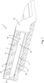
- Figure 1 shows a schematic perspective view of an embodiment of a scraper unit 7 for use in a cleaning unit 8, wherein the cleaning unit 8 is arranged for cleaning a sensor window pane 91 of an optical sensing device 90.
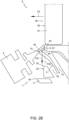
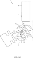
- Figures 2A-2F show schematic, partly cut-away, cross-sectional views of the cleaning unit in six different states of said cleaning unit 8.
- the cleaning unit 8 is for cleaning a sensor window pane 91 of an optical sensing device 90 of a car or another motor vehicle, in particular for cleaning the outer surface 92 of the sensor window pane 91.
- the optical sensing device 90 can preferably be for optical distance measurement, more preferably it can be a LiDAR sensor device.
- the cleaning unit 8 comprises a wiper blade 40, preferably of a resilient and/or rubber or rubberlike material.
- the cleaning unit 8 is arranged for wiping the wiper blade 40, preferably at least its tip 41, over the sensor window pane 91, and the cleaning unit 8 and/or the wiper blade 40 may be arranged for pushing water, other fluid, such as cleaning fluid or precipitation 6, and/or other impediments 6 to light transmittance, away from at least a portion of the sensor window pane 91, for instance in a wiping direction D1 parallel to the outer surface 92 of the sensor window pane 91.
- the cleaning unit 8 further comprises a first scraper 1 for scraping impediments 6 off the wiper blade 40. Further, the cleaning unit 8 is arranged for moving at least one of the wiper blade 40 and the first scraper 1 with respect to each other and along each other for scraping impediments 6 off the wiper blade 40.
- the first scraper 1 can be part of a scraping system or cleaning system for cleaning the wiper blade 40 at least partly.
- the first scraper 1 can be part of a scraper unit 7, which may be formed as an assembly comprising multiple parts 1, 2, 3 interconnected to each other, for instance by mounting them in a frame 70.
- the scraper unit 7 may alternatively be formed integrally, for instance by means of integrally injection molding said scraper unit 7.
- At least the first scraper 1, and preferably the entire scraping system 7, can be fixed with respect to the position of the sensor window pane 91 and wherein the cleaning unit 8 can in such embodiments then be arranged for moving the wiper blade 40 with respect to the first scraper 1 such as to scrape the wiper blade 40 along the scraper, and preferably also for moving the wiper blade 40 with respect to one or multiple optional further cleaning elements 2, 3 of the scraping system 7, such as for instance a wipe off surface 22 and/or a further scraper 3, which will be discussed in more detail here below.
- the cleaning unit 8 can be arranged for wiping the wiper blade 40 over the sensor window pane 91 from a first position, in particular a top position, towards a second position, in particular a lower position, such as to wipe at least a first portion of the sensor window pane 91 located between said first position and said second position, and wherein the cleaning unit 8 is arranged for moving the wiper blade 40 back from said second position substantially towards said first position without wiping over said first portion of the sensor window pane 91.
- the outer surface 92 of the sensor window pane 91 can extend upwards, preferably substantially vertically, and the wiper blade 40 may wipe at least a part of said outer surface 92, preferably by wiping in a downward direction D1.
- the wiper blade 40 wiping over the sensor window pane 91 may the push impediments 6 downwards, which may be beneficial, for instance as it does not have to work against gravitation.
- the wiper blade 40 may be moved away in a direction D4 substantially transverse to, and away from, the outer surface 92 of the sensor window pane 91.
- the wiper blade 40 may be moved away from the virtual plane P92 in which the outer surface 92 of the sensor window pane 91 extends by rotating the wiper blade 40 in a rotational direction R4, for instance about a rotation axis A4 of a wiper 4 including said wiper blade 40.
- unidirectional wiping in particular wiping from the first position to the second position and while refraining from wiping from the second substantially towards the first position, may give relatively good cleaning results, especially compared to bidirectional wiping.
- Refraining from wiping on the return movement of the wiper blade 40 from the second position substantially towards the first position may counteract a fluid film from being deployed onto the sensor window pane 91 during the return movement.
- the wiper blade 40 may thus be in contact with the sensor window pane 91 while wiping from the first position to the second position, whereas the wiper blade 40 may be disengaged from the sensor window pane 91 during movement of the wiper blade 40 from the second position substantially towards the first position.
- the wiper 4 and/or the wiper blade 40 may be held substantially in a certain state or position, in particular a certain rotational state or rotational position, and can be moved substantially linearly, in particular in a wiping direction D1, first along the sensor window pane 91, for instance as shown in Fig. 2A , and subsequently over the first scraper 1, for instance as shown in Fig. 2B .
- the first scraper 1 may protrude beyond a virtual plane P92 in which the outer face 92 of the sensor window pane 91 extends, as can be seen for instance in Fig. 2B .
- protruding can be considered as to mean projecting at the side of said virtual plane P92 opposite to the side at which the sensor window pane 91 is located. This is, in Fig. 2B , the sensor window pane 91 is located at the right side of said virtual plane P92, and the first scraper 1 protrudes to the left side of the virtual plane P92, which may correspond with the front side of the car or other motor vehicle provided with the cleaning unit 8.
- the first scraper 1 can define a first scraping edge 10, and the cleaning unit 8 can be arranged such as to allow said first scraper edge 10 to engage a side face 44 of the wiper blade 40 at a location spaced apart from a tip 41 of said wiper blade 40, as can be seen in Fig. 2B .
- the first scraper 1 in particular its first scraper edge 10 can scrape along said side face 44 of the wiper blade towards said tip 41 of the wiper blade 40, especially such as to scrape off impediments 6, 61, such as for instance bug parts, which then may be removed, in particular lead down, for instance by means of a first outlet channel 51 or the like.
- the first scraper 1 may have a relatively sharp edge 10, preferably such that its angle is smaller than 120°, preferably about 90°, such as is the case in the here shown embodiment, or smaller than 90°.
- the cleaning unit 8 may further comprise a wipe off surface 22, and the cleaning unit 8 may then be arranged for allowing the wiper blade tip 41 to sweep over said wipe off surface 22, as for instance can be understood from Fig. 2D .
- the cleaning unit 8 may then be arranged for allowing the wiper blade tip 41 to sweep over said wipe off surface 22, as for instance can be understood from Fig. 2D .
- liquid 62 and/or other impediments which may be present at or near the wiper blade tip 41, in particular on or at a bottom plane 42 of the wiper blade 40, in case the wiper blade 40 has such bottom plane, may be swept off from the wiper blade 40 onto the wipe off surface 22.
- the wipe off surface 22 can be located downstream from the first scraper.
- the first scraper edge 10 can be located between the sensor window pane 91 and the wipe off surface 22.
- the wipe off surface 22 can be located substantially parallel to the sensor window pane 91, in particular substantially parallel to the outer face 92 of the sensor window pane 91.
- the wipe off surface 22 may be substantially in line with the outer face 92 of the sensor window pane 91, as can be seen in Figs. 2A-2F , and may for instance be offset therefrom over less than 5, preferably less than 3 mm, more preferably less than 1 mm.
- the first scraper 1 may preferably protrude beyond the virtual plane P22 in which the wipe off surface 22 extends, in particular in the outward direction D3, which may be considered as a direction D3 transverse to the wipe off surface 22 and/or the virtual plane P22 in which said wipe off surface 22 extends.
- the wipe off surface 22 is spaced apart from the first scraper edge 10, and preferably is spaced apart from the first scraper 1, for instance spaced apart in the downward direction and/or the direction D2 in which the wiper blade 40 is moved, such as to form an outlet channel 52, for instance a second outlet channel 52, for removing impediments removed from the wiper blade 40.
- an outlet channel 52 for instance a second outlet channel 52
- impediments 61 such as for instance relatively large and/or solid parts 61 may be removed via the first outlet channel 51, as for instance can be seen in Fig. 2C .
- the wipe off surface 22 can be formed by a second scraper 2.
- Said second scraper 2 can then comprise a second scraper edge 20, preferably located at a proximal end of the wipe off surface 22, which proximal end in the here shown embodiment is located at a top side of said wipe off surface 22.
- the second scraper 2 may have a relatively sharp edge 20, preferably such that its angle is smaller than 120°, preferably about 90°, such as is the case in the here shown embodiment, or smaller than 90°.
- the second scraper edge 20 may scrape along a side face 44 of the wiper blade 40, preferably in a direction towards the tip 41 of the wiper blade 40, preferably substantially before said tip 41 is swiped over the wipe off surface 22 where it for instance may deposit a film of liquid, and/or other impediments.
- the wipe out surface 22, and preferably also its portion over which the wiper blade 44 actually wipes may have a length L22, which may be measured in the direction D2 in which the wiper blade 40 wipes over said wipe out surface 22, wherein said length L22, in the here shown exemplary embodiment formed as the height of said wipe out surface 22, can be at least 1 mm, preferably at least 2 mm, more preferably at least 3 mm, such as at least about 5 mm.
- said length L22 may be at least equal to and preferably larger than the thickness T41 of the tip 41 of the wiper blade 40 and/or the thickness T42 of the bottom plane 42 of the wiper blade 40, preferably being at least two times, more preferably at least three times as large.
- Said impediments in particular liquid impediments, may flow down along the wipe off surface 22, and may preferably be removed, in particular drained, by means of a respective outlet channel 53, in particular a third outlet channel 53.
- said outlet channel 53 may be located adjacent to a downstream end of the wipe off surface 22, wherein downstream is considered downstream in the direction D2 in which the wiper blade is moved, said downstream end preferably being a lower end of the wipe off surface 22.
- said outlet channel 53 may form a drainage slit 53 which may be arranged for letting water through said slit by means of capillarity, as will be appreciated and understand by the person skilled in the art.
- the drainage slit may drain the liquid from an inlet opening 531 of the drainage slit 53 located near the downstream end of the wipe off surface 22 and towards an outlet opening 532 of the drainage slit located opposite to the inlet opening 531.
- wall surfaces defining the capillary drainage slit 53 which may be relatively smooth, may extend substantially parallel to each other. Additionally or alternatively, said wall surfaces may be offset with respect to each other over a distance of preferably less than 2 mm, for example a distance between 0.1 mm and 1 mm, such as between 0.25 mm and 0.5 mm.
- the liquid may preferably be drained by means of a capillarity effect provided by said drainage slit 53, in embodiments, alternatively or additionally, active suction means may be provided.
- active suction means may be provided for the third outlet channel 53, but may additionally or alternatively be provided for one or more other ones of the outlet channels 51, 52.
- the wipe off surface 22 can be formed by an element formed as a second scraper 2 defining the second scraper edge 20 at a proximal end of the wipe off surface 22, that is not necessary.
- the proximal end, in particular an upper end, of the wipe off surface 22 it may curve away, for instance by blending into another surface, in particular a top surface, of the element 2 defining said wipe off surface 22.
- a gap and/or an outlet channel 51 can be present between the first scraper 1 and the element defining the second scraper edge 20, this is not necessary either.
- the wipe off surface 22 may be formed by the first scraper 1, and the wipe off surface 22 shown in the embodiment of Fig. 2A may in such alternative embodiment for instance extend all the way up to the bottom side 11 of the first scraper 1.
- the cleaning unit 8 can comprise a further scraper 3, in particular a third scraper 3.
- said further scraper 3 can protrude beyond the virtual plane P22 in which the wipe off surface 22 extends and/or beyond the virtual P92 in which the outer face 92 of the sensor window pane 91 extends.
- Said further scraper 3, in particular a scraping edge 30 thereof, may facilitate that any contamination still remaining on the wiper blade 40, after said wiper blade 40 has been swept over the wipe off surface 22, may be removed from said wiper blade 40 at least partly.
- said scraping edge 30 may define an acute angle ⁇ 30, preferably of less than 75°, more preferably less than 60°, such as about 50°, about 45°, or less.
- a lower face 31 of the further scraper 3 extends from the scraping edge 30 of said scraper 3 and slopes away in a backward direction, especially backwards towards the virtual plane P92 in which the outer face 92 of the sensor window pane 91 extends.
- Such relatively sharp angle or so-called acute angel ⁇ 30 may counteract that water droplets and/or other impediments removed from the wiper blade 40 may stay behind at said further scraping edge 30.
- the drainage slit 53 can be formed between an element 2 defining the wipe off surface 22 and a further element 3, preferably a further element 3 defining the further scraper 3 and/or its scraper edge 30.
- the wiper blade 40 especially its tip 41, may thus first be wiped over at least a portion of the outer surface 92 of the sensor window pane 91, in particular in a substantially downward direction D1, as shown in Fig. 2A . Subsequently, the wiper blade 40, which may be moved further, in particular further downwards D2, may abut a first scraper 1, which may scrape off at least a portion of impediments 61 accumulated on the wiper blade 40, as shown in Fig. 2B .
- the wiper blade 40 which may be moved further, in particular further downwards D2, may encounter the element 2 defining the wipe off surface 22, and in an embodiment in which said element 2 is provided with an additional scraping edge 20, said edge 20 may scrape off at least a further portion of impediments accumulated on the wiper blade 40, as shown in Fig. 2C .
- said element 2 may be formed differently, and may for example have a rounded upper edge which can serve as part of the wipe off surface 22.
- the wiper blade 40 in particular its tip 41, may be swept over the wipe off surface 22, as can be seen in Fig.
- the wiper blade 40 may be moved back to the first position on the outer surface 92 of the sensor window pane 91, preferably without the wiper blade 40 wiping over the sensor window pane 91 when it returns to said first position.
- said the wiper blade 40 may for example be moved in an outward direction D4, and/or may be tilted R4 to a certain extent.
- the wiper blade 40 may be brought back in its initial state, which may correspond substantially with the rotational state of the wiper 4 and/or of the wiper blade 40 shown in Fig. 2A .
- unidirectional wiping in particular wiping from the first position to the second position and while refraining from wiping from the second substantially towards the first position, may give relatively good cleaning results, especially compared to bidirectional wiping.
- Refraining from wiping on the return movement of the wiper blade 40 from the second position substantially towards the first position may counteract a fluid film from being deployed onto the sensor window pane 91 during the return movement.
- the wiper blade 40 may thus be in contact with the sensor window pane 91 while wiping from the first position to the second position, whereas the wiper blade 40 may be disengaged from the sensor window pane 91 during movement of the wiper blade 40 from the second position substantially towards the first position.
- the wiper blade 40 may nevertheless also wipe the sensor window pane 91 when moving back.
- the cleaning unit 7 may be arranged for bidirectional wiping, i.e. wiping back and forth, wherein the wiper blade 40 is cleaned at least partly by scraping off impediments at least partly by means of at least a first scraper 1 before wiping backwards over the sensor window pane 91.
- the wiper 4 and/or the wiper blade 40 may be held substantially in a certain position, in particular a certain rotational position, and can be moved substantially linearly, in particular in a wiping direction D1 and/or a substantially downward direction D2, first along the sensor window pane 91, and subsequently over the first scraper 1.
- the wiper 4 and/or the wiper blade 40 may subsequently be still held substantially in said certain predetermined position when it may subsequently be moved along the wipe off surface 22.
- the wiper 4 and/or the wiper blade 40 which may be an elongate wiper blade 40 extending in a direction transverse to the plane of the drawing, may be in substantially the same position with respect to the outer surface of the sensor window pane 91 during wiping said sensor window pane 91 as with respect to the wipe off surface 22 when wiping over said wipe off surface 22.
- the wiper 4 and/or the wiper blade 40 may be moved under an angle ⁇ 4, ⁇ 40 with respect to the normal n92, n22, nD1, nD2 to the sensor window pane's outer surface 92 and/or the wipe off surface 22 and/or the direction in which the wiper 4 and/or wiper blade 40 is moved, wherein said angle ⁇ 4, ⁇ 40 may be an acute angle, preferably between 20° and 70°, more preferably between 30° and 60°, such as between 40° and 50°, for example about 45°.
- said wiper blade 40 may be tilted such that while moving it back to said first position it may be in another rotational position in which it does not touch the sensor window pane 91.
- the wiper blade 40 may also be tilted or rotated prior to returning the wiper, in particular substantially to a rotational position substantially mirrored with respect to the rotational position in Fig. 2A , such as to facilitate that the wiper blade 40 may wipe impediments off from the sensor window pane 91 on the return run.
- a second scraper unit may be provided, in particular at an opposite end of the sensor window pane 91, for example above the sensor window pane 91 in case of an upwardly, preferably substantially vertically, extending sensor window pane outer surface 92.
Landscapes
- Engineering & Computer Science (AREA)
- Mechanical Engineering (AREA)
- Cleaning In General (AREA)
- Optical Measuring Cells (AREA)
Claims (17)
- Reinigungseinheit (8) zum Reinigen einer Sensorfensterscheibe (91) einer optischen Sensoreinrichtung (90) eines Kraftfahrzeugs, wobei die Reinigungseinheit (8) ein Wischerblatt (40) umfasst, wobei die Reinigungseinheit (8) ferner mindestens einen ersten Abstreifer (1) zum Abstreifen von Hindernissen (61) vom Wischerblatt (40) umfasst, wobei die Reinigungseinheit (8) zum Wischen des Wischerblatts (40) über die Sensorfensterscheibe (91) angeordnet ist, wobei die Reinigungseinheit (8) ferner so angeordnet ist, dass sie das Wischerblatt (40) in Bezug auf und entlang des ersten Abstreifers (1) und/oder den ersten Abstreifer (1) in Bezug auf und entlang des Wischerblatts (40) bewegt, um Hindernisse (61) von dem Wischerblatt (40) abzustreifen,
dadurch gekennzeichnet,
dass die Reinigungseinheit (8) eine Abwischfläche (22) umfasst, und wobei die Reinigungseinheit (8) so angeordnet ist, dass die Wischerblattspitze (41) über die Abwischfläche (22) streichen kann, wobei die Abwischfläche (22) von einer ersten Abstreiferkante (10) beabstandet ist, wobei die Reinigungseinheit (8) ferner einen weiteren Abstreifer (3) umfasst, wobei sich die Sensorfensterscheibe (91) im Wesentlichen nach oben erstreckt, wobei sich der weitere Abstreifer (3) auf einem Höhenniveau unterhalb eines unteren Endes der Sensorfensterscheibe (91) befindet, wobei der weitere Abstreifer (3) eine weitere Abstreiferkante und eine untere Fläche aufweist, wobei sich die untere Fläche von der weiteren Abstreiferkante aus erstreckt und in einer rückwärtigen Richtung zu der virtuellen Ebene (P92) hin abfällt, in der sich die Außenfläche (92) der Sensorfensterscheibe (91) erstreckt. - Reinigungseinheit (8) nach Anspruch 1, wobei der erste Abstreifer (1) in Bezug auf die Position der Sensorfensterscheibe (91) fixiert ist, und wobei die Reinigungseinheit (8) zum Bewegen des Wischerblatts (40) in Bezug auf den ersten Abstreifer (1) angeordnet ist, um das Wischerblatt (40) entlang des Abstreifers (1) abzustreifen.
- Reinigungseinheit (8) nach Anspruch 1 oder 2, wobei der erste Abstreifer (1) über eine virtuelle Ebene (P92) hinausragt, in der sich die Außenfläche (92) der Sensorfensterscheibe (91) erstreckt.
- Reinigungseinheit (8) nach einem der vorhergehenden Ansprüche, wobei der erste Abstreifer (1) die erste Abstreiferkante (10) definiert und wobei die Reinigungseinheit (8) so angeordnet ist, dass die erste Abstreiferkante (10) mit einer Seitenfläche (44) des Wischerblatts (40) an einer von einer Spitze (41) des Wischerblatts (40) beabstandeten Stelle in Eingriff kommen kann und dann entlang der Seitenfläche (44) in Richtung der Spitze (41) abstreift.
- Reinigungseinheit (8) nach einem der vorhergehenden Ansprüche, wobei die Abwischfläche (22) stromabwärts des ersten Abstreifers (1) angeordnet ist.
- Reinigungseinheit (8) nach einem der vorhergehenden Ansprüche, wobei die Abwischfläche (22) im Wesentlichen parallel zur Sensorfensterscheibe (91) angeordnet ist.
- Reinigungseinheit (8) nach einem der vorhergehenden Ansprüche, wobei der erste Abstreifer (1) über eine virtuelle Ebene (P22) hinausragt, in der sich die Abwischfläche (22) erstreckt.
- Reinigungseinheit (8) nach einem der vorhergehenden Ansprüche, wobei die Abwischfläche (22) von dem ersten Abstreifer (1) beabstandet ist.
- Reinigungseinheit (8) nach einem der vorhergehenden Ansprüche, insbesondere nach Anspruch 6, wobei die Abwischfläche (22) durch einen zweiten Abstreifer (2) gebildet wird, und wobei der zweite Abstreifer (2) eine zweite Abstreiferkante (20) umfasst, die vorzugsweise an einem proximalen Ende der Abstreiffläche (22) angeordnet ist.
- Reinigungseinheit (8) nach Anspruch 1, wobei der weitere Abstreifer eine Abstreiferkante umfasst, die einen spitzen Winkel definiert.
- Reinigungseinheit (8) nach einem der vorhergehenden Ansprüche, wobei benachbart zu einem stromabwärtigen Ende der Abwischfläche (22) ein Abflussschlitz zum Ablassen von Flüssigkeit, die von dem Wischerblatt (40) abgestreift wurde, auf die Abstreiffläche (22) vorgesehen ist.
- Reinigungseinheit (8) nach Anspruch 11, wobei der Abflussschlitz so angeordnet ist, dass er mittels Kapillarität Wasser durch den Schlitz durchlässt.
- Reinigungseinheit (8) nach Anspruch 11 oder 12, wobei der Abflussschlitz zwischen einem Element, das die Abwischfläche (22) definiert, und einem weiteren Element, vorzugsweise einem weiteren Element, das den weiteren Abstreifer definiert, ausgebildet ist.
- Reinigungseinheit (8) nach einem der vorhergehenden Ansprüche, wobei die Reinigungseinheit (8) zum Wischen des Wischerblatts (40) über die Sensorfensterscheibe (91) von einer ersten Position, insbesondere einer oberen Position, in Richtung einer zweiten Position, insbesondere einer unteren Position, angeordnet ist, um mindestens einen ersten Abschnitt der Sensorfensterscheibe (91), der sich zwischen der ersten Position und der zweiten Position befindet, zu wischen, und wobei die Reinigungseinheit (8) so angeordnet ist, dass sie das Wischerblatt (40) von der zweiten Position im Wesentlichen in Richtung der ersten Position zurückbewegt, ohne über den ersten Abschnitt der Sensorfensterscheibe (91) zu wischen.
- Verfahren zum Reinigen einer Sensorfensterscheibe (91) einer optischen Sensoreinrichtung (90) eines Kraftfahrzeugs unter Verwendung der Reinigungseinheit nach Anspruch 1, umfassend die Schritte:Wischen mindestens eines Abschnitts der Sensorfensterscheibe (91) mittels eines Wischerblatts (40); undAbstreifen entlang einer Seitenfläche (44) des Wischerblatts (40), vorzugsweise in Richtung einer Spitze (41) des Wischerblatts (40), ferner umfassend einen anschließenden Schritt des Überstreichens der Spitze (41) des Wischerblatts (40) über eine Abwischfläche (22), um Flüssigkeit und/oder andere Hindernisse (61) vom Wischerblatt (40) und auf die Abwischfläche (22) abzuwischen, wobei die Abwischfläche (22) von einer ersten Abstreiferkante (10) beabstandet ist, um einen Auslasskanal (52) zum Entfernen von Hindernissen zu bilden, die von dem Wischerblatt (40) entfernt wurden, bevor das Wischerblatt (40) erneut über mindestens einen Abschnitt der Sensorfensterscheibe (91) gewischt wird.
- Verfahren nach Anspruch 15, das einen weiteren Schritt umfasst, bei dem ein zweites Mal entlang der Seitenfläche (44) des Wischers abgestreift wird, vorzugsweise in Richtung einer Spitze (41) des Wischerblatts (40).
- Optische Sensoreinrichtung (90), vorzugsweise eine optische Sensoreinrichtung (90) zur optischen Abstandsmessung, stärker bevorzugt eine LiDAR-Sensorvorrichtung, wobei die optische Abtastvorrichtung (90) mit einer Reinigungseinheit (8) nach einem der Ansprüche 1 bis 14 versehen ist.
Applications Claiming Priority (2)
| Application Number | Priority Date | Filing Date | Title |
|---|---|---|---|
| NL2024098A NL2024098B1 (en) | 2019-10-24 | 2019-10-24 | Cleaning unit, scraper unit, optical sensing device and method for cleaning |
| PCT/NL2020/050658 WO2021080430A1 (en) | 2019-10-24 | 2020-10-23 | Cleaning unit, scraper unit, optical sensing device and method for cleaning |
Publications (2)
| Publication Number | Publication Date |
|---|---|
| EP4048558A1 EP4048558A1 (de) | 2022-08-31 |
| EP4048558B1 true EP4048558B1 (de) | 2025-04-30 |
Family
ID=69570787
Family Applications (1)
| Application Number | Title | Priority Date | Filing Date |
|---|---|---|---|
| EP20803292.0A Active EP4048558B1 (de) | 2019-10-24 | 2020-10-23 | Reinigungseinheit, optische abtastvorrichtung und verfahren zum reinigen |
Country Status (7)
| Country | Link |
|---|---|
| US (1) | US12187238B2 (de) |
| EP (1) | EP4048558B1 (de) |
| JP (1) | JP7741063B2 (de) |
| KR (1) | KR20220079887A (de) |
| CN (1) | CN114466774B (de) |
| NL (1) | NL2024098B1 (de) |
| WO (1) | WO2021080430A1 (de) |
Families Citing this family (2)
| Publication number | Priority date | Publication date | Assignee | Title |
|---|---|---|---|---|
| FR3127458B1 (fr) * | 2021-09-30 | 2024-01-05 | Valeo Systemes Dessuyage | Système de nettoyage de dispositifs optiques |
| US12330599B2 (en) * | 2023-08-04 | 2025-06-17 | Alps Alpine Co., Ltd. | Sensor lens cleaning system |
Citations (2)
| Publication number | Priority date | Publication date | Assignee | Title |
|---|---|---|---|---|
| DE3138388A1 (de) * | 1980-09-30 | 1982-08-05 | Niels Oluf 2670 Greve Strand Skipper | Vorrichtung zum reinigen von wischblaettern |
| EP0832798B1 (de) * | 1996-09-13 | 2001-09-26 | Mitsuba Corporation Co., Ltd. | Bilderkennungssystem |
Family Cites Families (10)
| Publication number | Priority date | Publication date | Assignee | Title |
|---|---|---|---|---|
| DE1911991A1 (de) * | 1969-03-10 | 1970-09-24 | Julius Neubauer | Wischblatt-Reiniger |
| DE2936823A1 (de) | 1979-09-12 | 1981-04-09 | Vereinigte Glaswerke Gmbh, 5100 Aachen | Windschutzscheibe fuer kraftfahrzeuge |
| USRE32218E (en) * | 1979-09-12 | 1986-07-29 | Verienigte Glaswerke GmbH | Automotive windshield |
| JPH06179348A (ja) | 1992-12-16 | 1994-06-28 | Nissan Motor Co Ltd | 車両用ワイパー装置 |
| SE506137C3 (sv) | 1994-01-17 | 1997-12-22 | Dick Pettersson | Anordning foer rengoering av bladet i en vindrutetorkare paa fordon |
| JP2005205929A (ja) | 2004-01-20 | 2005-08-04 | Mitsuba Corp | ワイパ装置 |
| US7596828B2 (en) * | 2007-08-27 | 2009-10-06 | Evdokimo Arnold W | Multiple blade windshield wiper |
| SE535181C2 (sv) * | 2010-02-17 | 2012-05-08 | Qleeno Ab | Ring med skraparlister för skurmaskiner |
| FR3031943B1 (fr) | 2015-01-22 | 2017-02-17 | Valeo Systemes Dessuyage | Systeme de vision arriere et procede de fonctionnement du systeme |
| US10259431B1 (en) * | 2017-12-19 | 2019-04-16 | GM Global Technology Operations LLC | Self-centering wiper system for an optical device |
-
2019
- 2019-10-24 NL NL2024098A patent/NL2024098B1/en active
-
2020
- 2020-10-23 EP EP20803292.0A patent/EP4048558B1/de active Active
- 2020-10-23 KR KR1020227014352A patent/KR20220079887A/ko not_active Ceased
- 2020-10-23 US US17/762,919 patent/US12187238B2/en active Active
- 2020-10-23 CN CN202080068679.1A patent/CN114466774B/zh active Active
- 2020-10-23 WO PCT/NL2020/050658 patent/WO2021080430A1/en not_active Ceased
- 2020-10-23 JP JP2022510074A patent/JP7741063B2/ja active Active
Patent Citations (2)
| Publication number | Priority date | Publication date | Assignee | Title |
|---|---|---|---|---|
| DE3138388A1 (de) * | 1980-09-30 | 1982-08-05 | Niels Oluf 2670 Greve Strand Skipper | Vorrichtung zum reinigen von wischblaettern |
| EP0832798B1 (de) * | 1996-09-13 | 2001-09-26 | Mitsuba Corporation Co., Ltd. | Bilderkennungssystem |
Also Published As
| Publication number | Publication date |
|---|---|
| JP7741063B2 (ja) | 2025-09-17 |
| CN114466774A (zh) | 2022-05-10 |
| US12187238B2 (en) | 2025-01-07 |
| WO2021080430A1 (en) | 2021-04-29 |
| CN114466774B (zh) | 2024-10-29 |
| EP4048558A1 (de) | 2022-08-31 |
| US20220332288A1 (en) | 2022-10-20 |
| JP2022552934A (ja) | 2022-12-21 |
| KR20220079887A (ko) | 2022-06-14 |
| NL2024098B1 (en) | 2021-07-13 |
Similar Documents
| Publication | Publication Date | Title |
|---|---|---|
| US11782142B2 (en) | Device designed to detect surroundings and method for cleaning a cover of a device of this type | |
| JP7751561B2 (ja) | 清掃装置および光学センサデバイスをクリーニングする方法 | |
| EP4048558B1 (de) | Reinigungseinheit, optische abtastvorrichtung und verfahren zum reinigen | |
| CN102861727B (zh) | 用于从传感器机身的端板清洁沉积物和增积物的设备和方法 | |
| CN105480202B (zh) | 用于擦拭玻璃的机动车辆表面的风挡擦拭器、系统和方法 | |
| CN111417887A (zh) | 用于环境感测的设备和用于清洁这种设备的遮盖件的方法 | |
| CN108501873A (zh) | 传感器和清洁装置 | |
| GB2578649A (en) | Lens cleaning device | |
| CN114951055A (zh) | 用于相机、传感器、激光雷达等的带有非接触表面清洁系统的传感器组件 | |
| US11420595B2 (en) | Cleaning unit for cleaning foreign matter from a cover, in particular a cover of a transmitter/receiver window of a driving environment sensor, and device for sensing the environment and method | |
| JP7655748B2 (ja) | 車両 | |
| EP4416019B1 (de) | Verbesserte sensorreinigung auf basis der erforderlichen reinigungsintensität | |
| EP3165418B1 (de) | Steuerverfahren eines wisch-/waschsystems für die scheibe eines fahrzeugs, und system zur verwendung desselben | |
| US20160272160A1 (en) | Enhanced wiper assembly | |
| CN216217102U (zh) | 图像传感器的防护装置以及车辆 | |
| CN119928777A (zh) | 碎屑管理滑块 | |
| CN114025059A (zh) | 图像传感器的防护装置以及车辆 | |
| CN121019493A (zh) | 车辆前挡风玻璃的清洁方法和装置 | |
| CN118695970A (zh) | 用于擦拭车辆的至少一个光学元件的光学表面的装置 | |
| TR2022016271U5 (tr) | Çi̇ft tarafli kullanim özelli̇ği̇ne sahi̇p bi̇r si̇lecek | |
| KR20140144094A (ko) | 차량 와이퍼의 와이퍼 스트립 |
Legal Events
| Date | Code | Title | Description |
|---|---|---|---|
| STAA | Information on the status of an ep patent application or granted ep patent |
Free format text: STATUS: UNKNOWN |
|
| STAA | Information on the status of an ep patent application or granted ep patent |
Free format text: STATUS: THE INTERNATIONAL PUBLICATION HAS BEEN MADE |
|
| PUAI | Public reference made under article 153(3) epc to a published international application that has entered the european phase |
Free format text: ORIGINAL CODE: 0009012 |
|
| STAA | Information on the status of an ep patent application or granted ep patent |
Free format text: STATUS: REQUEST FOR EXAMINATION WAS MADE |
|
| 17P | Request for examination filed |
Effective date: 20220509 |
|
| AK | Designated contracting states |
Kind code of ref document: A1 Designated state(s): AL AT BE BG CH CY CZ DE DK EE ES FI FR GB GR HR HU IE IS IT LI LT LU LV MC MK MT NL NO PL PT RO RS SE SI SK SM TR |
|
| DAV | Request for validation of the european patent (deleted) | ||
| DAX | Request for extension of the european patent (deleted) | ||
| P01 | Opt-out of the competence of the unified patent court (upc) registered |
Effective date: 20230516 |
|
| STAA | Information on the status of an ep patent application or granted ep patent |
Free format text: STATUS: EXAMINATION IS IN PROGRESS |
|
| 17Q | First examination report despatched |
Effective date: 20231002 |
|
| GRAP | Despatch of communication of intention to grant a patent |
Free format text: ORIGINAL CODE: EPIDOSNIGR1 |
|
| STAA | Information on the status of an ep patent application or granted ep patent |
Free format text: STATUS: GRANT OF PATENT IS INTENDED |
|
| INTG | Intention to grant announced |
Effective date: 20241126 |
|
| GRAS | Grant fee paid |
Free format text: ORIGINAL CODE: EPIDOSNIGR3 |
|
| GRAA | (expected) grant |
Free format text: ORIGINAL CODE: 0009210 |
|
| STAA | Information on the status of an ep patent application or granted ep patent |
Free format text: STATUS: THE PATENT HAS BEEN GRANTED |
|
| AK | Designated contracting states |
Kind code of ref document: B1 Designated state(s): AL AT BE BG CH CY CZ DE DK EE ES FI FR GB GR HR HU IE IS IT LI LT LU LV MC MK MT NL NO PL PT RO RS SE SI SK SM TR |
|
| REG | Reference to a national code |
Ref country code: CH Ref legal event code: EP Ref country code: GB Ref legal event code: FG4D |
|
| REG | Reference to a national code |
Ref country code: DE Ref legal event code: R096 Ref document number: 602020050509 Country of ref document: DE |
|
| REG | Reference to a national code |
Ref country code: IE Ref legal event code: FG4D |
|
| REG | Reference to a national code |
Ref country code: NL Ref legal event code: MP Effective date: 20250430 |
|
| REG | Reference to a national code |
Ref country code: AT Ref legal event code: MK05 Ref document number: 1789779 Country of ref document: AT Kind code of ref document: T Effective date: 20250430 |
|
| PG25 | Lapsed in a contracting state [announced via postgrant information from national office to epo] |
Ref country code: FI Free format text: LAPSE BECAUSE OF FAILURE TO SUBMIT A TRANSLATION OF THE DESCRIPTION OR TO PAY THE FEE WITHIN THE PRESCRIBED TIME-LIMIT Effective date: 20250430 Ref country code: PT Free format text: LAPSE BECAUSE OF FAILURE TO SUBMIT A TRANSLATION OF THE DESCRIPTION OR TO PAY THE FEE WITHIN THE PRESCRIBED TIME-LIMIT Effective date: 20250901 Ref country code: ES Free format text: LAPSE BECAUSE OF FAILURE TO SUBMIT A TRANSLATION OF THE DESCRIPTION OR TO PAY THE FEE WITHIN THE PRESCRIBED TIME-LIMIT Effective date: 20250430 |
|
| REG | Reference to a national code |
Ref country code: LT Ref legal event code: MG9D |
|
| PG25 | Lapsed in a contracting state [announced via postgrant information from national office to epo] |
Ref country code: NO Free format text: LAPSE BECAUSE OF FAILURE TO SUBMIT A TRANSLATION OF THE DESCRIPTION OR TO PAY THE FEE WITHIN THE PRESCRIBED TIME-LIMIT Effective date: 20250730 Ref country code: GR Free format text: LAPSE BECAUSE OF FAILURE TO SUBMIT A TRANSLATION OF THE DESCRIPTION OR TO PAY THE FEE WITHIN THE PRESCRIBED TIME-LIMIT Effective date: 20250731 |
|
| PG25 | Lapsed in a contracting state [announced via postgrant information from national office to epo] |
Ref country code: NL Free format text: LAPSE BECAUSE OF FAILURE TO SUBMIT A TRANSLATION OF THE DESCRIPTION OR TO PAY THE FEE WITHIN THE PRESCRIBED TIME-LIMIT Effective date: 20250430 Ref country code: PL Free format text: LAPSE BECAUSE OF FAILURE TO SUBMIT A TRANSLATION OF THE DESCRIPTION OR TO PAY THE FEE WITHIN THE PRESCRIBED TIME-LIMIT Effective date: 20250430 |
|
| PG25 | Lapsed in a contracting state [announced via postgrant information from national office to epo] |
Ref country code: BG Free format text: LAPSE BECAUSE OF FAILURE TO SUBMIT A TRANSLATION OF THE DESCRIPTION OR TO PAY THE FEE WITHIN THE PRESCRIBED TIME-LIMIT Effective date: 20250430 |
|
| PG25 | Lapsed in a contracting state [announced via postgrant information from national office to epo] |
Ref country code: HR Free format text: LAPSE BECAUSE OF FAILURE TO SUBMIT A TRANSLATION OF THE DESCRIPTION OR TO PAY THE FEE WITHIN THE PRESCRIBED TIME-LIMIT Effective date: 20250430 |
|
| PG25 | Lapsed in a contracting state [announced via postgrant information from national office to epo] |
Ref country code: AT Free format text: LAPSE BECAUSE OF FAILURE TO SUBMIT A TRANSLATION OF THE DESCRIPTION OR TO PAY THE FEE WITHIN THE PRESCRIBED TIME-LIMIT Effective date: 20250430 |
|
| PG25 | Lapsed in a contracting state [announced via postgrant information from national office to epo] |
Ref country code: RS Free format text: LAPSE BECAUSE OF FAILURE TO SUBMIT A TRANSLATION OF THE DESCRIPTION OR TO PAY THE FEE WITHIN THE PRESCRIBED TIME-LIMIT Effective date: 20250731 |
|
| PG25 | Lapsed in a contracting state [announced via postgrant information from national office to epo] |
Ref country code: IS Free format text: LAPSE BECAUSE OF FAILURE TO SUBMIT A TRANSLATION OF THE DESCRIPTION OR TO PAY THE FEE WITHIN THE PRESCRIBED TIME-LIMIT Effective date: 20250830 |
|
| PG25 | Lapsed in a contracting state [announced via postgrant information from national office to epo] |
Ref country code: LV Free format text: LAPSE BECAUSE OF FAILURE TO SUBMIT A TRANSLATION OF THE DESCRIPTION OR TO PAY THE FEE WITHIN THE PRESCRIBED TIME-LIMIT Effective date: 20250430 |
|
| PGFP | Annual fee paid to national office [announced via postgrant information from national office to epo] |
Ref country code: DE Payment date: 20251021 Year of fee payment: 6 |
|
| PGFP | Annual fee paid to national office [announced via postgrant information from national office to epo] |
Ref country code: GB Payment date: 20251022 Year of fee payment: 6 |
|
| PG25 | Lapsed in a contracting state [announced via postgrant information from national office to epo] |
Ref country code: DK Free format text: LAPSE BECAUSE OF FAILURE TO SUBMIT A TRANSLATION OF THE DESCRIPTION OR TO PAY THE FEE WITHIN THE PRESCRIBED TIME-LIMIT Effective date: 20250430 Ref country code: SM Free format text: LAPSE BECAUSE OF FAILURE TO SUBMIT A TRANSLATION OF THE DESCRIPTION OR TO PAY THE FEE WITHIN THE PRESCRIBED TIME-LIMIT Effective date: 20250430 |
|
| PGFP | Annual fee paid to national office [announced via postgrant information from national office to epo] |
Ref country code: FR Payment date: 20251030 Year of fee payment: 6 |
|
| PG25 | Lapsed in a contracting state [announced via postgrant information from national office to epo] |
Ref country code: CZ Free format text: LAPSE BECAUSE OF FAILURE TO SUBMIT A TRANSLATION OF THE DESCRIPTION OR TO PAY THE FEE WITHIN THE PRESCRIBED TIME-LIMIT Effective date: 20250430 |
|
| PG25 | Lapsed in a contracting state [announced via postgrant information from national office to epo] |
Ref country code: EE Free format text: LAPSE BECAUSE OF FAILURE TO SUBMIT A TRANSLATION OF THE DESCRIPTION OR TO PAY THE FEE WITHIN THE PRESCRIBED TIME-LIMIT Effective date: 20250430 |
|
| PG25 | Lapsed in a contracting state [announced via postgrant information from national office to epo] |
Ref country code: SK Free format text: LAPSE BECAUSE OF FAILURE TO SUBMIT A TRANSLATION OF THE DESCRIPTION OR TO PAY THE FEE WITHIN THE PRESCRIBED TIME-LIMIT Effective date: 20250430 |
|
| PG25 | Lapsed in a contracting state [announced via postgrant information from national office to epo] |
Ref country code: IT Free format text: LAPSE BECAUSE OF FAILURE TO SUBMIT A TRANSLATION OF THE DESCRIPTION OR TO PAY THE FEE WITHIN THE PRESCRIBED TIME-LIMIT Effective date: 20250430 |
|
| PG25 | Lapsed in a contracting state [announced via postgrant information from national office to epo] |
Ref country code: RO Free format text: LAPSE BECAUSE OF FAILURE TO SUBMIT A TRANSLATION OF THE DESCRIPTION OR TO PAY THE FEE WITHIN THE PRESCRIBED TIME-LIMIT Effective date: 20250430 |