EP4048102B1 - Aerosolerzeugungsvorrichtung - Google Patents
Aerosolerzeugungsvorrichtung Download PDFInfo
- Publication number
- EP4048102B1 EP4048102B1 EP21841302.9A EP21841302A EP4048102B1 EP 4048102 B1 EP4048102 B1 EP 4048102B1 EP 21841302 A EP21841302 A EP 21841302A EP 4048102 B1 EP4048102 B1 EP 4048102B1
- Authority
- EP
- European Patent Office
- Prior art keywords
- aerosol generating
- generating device
- heater
- puff
- power signal
- Prior art date
- Legal status (The legal status is an assumption and is not a legal conclusion. Google has not performed a legal analysis and makes no representation as to the accuracy of the status listed.)
- Active
Links
Images


Classifications
-
- A—HUMAN NECESSITIES
- A61—MEDICAL OR VETERINARY SCIENCE; HYGIENE
- A61M—DEVICES FOR INTRODUCING MEDIA INTO, OR ONTO, THE BODY; DEVICES FOR TRANSDUCING BODY MEDIA OR FOR TAKING MEDIA FROM THE BODY; DEVICES FOR PRODUCING OR ENDING SLEEP OR STUPOR
- A61M11/00—Sprayers or atomisers specially adapted for therapeutic purposes
- A61M11/04—Sprayers or atomisers specially adapted for therapeutic purposes operated by the vapour pressure of the liquid to be sprayed or atomised
- A61M11/041—Sprayers or atomisers specially adapted for therapeutic purposes operated by the vapour pressure of the liquid to be sprayed or atomised using heaters
- A61M11/042—Sprayers or atomisers specially adapted for therapeutic purposes operated by the vapour pressure of the liquid to be sprayed or atomised using heaters electrical
-
- A—HUMAN NECESSITIES
- A24—TOBACCO; CIGARS; CIGARETTES; SIMULATED SMOKING DEVICES; SMOKERS' REQUISITES
- A24F—SMOKERS' REQUISITES; MATCH BOXES; SIMULATED SMOKING DEVICES
- A24F40/00—Electrically operated smoking devices; Component parts thereof; Manufacture thereof; Maintenance or testing thereof; Charging means specially adapted therefor
- A24F40/50—Control or monitoring
- A24F40/51—Arrangement of sensors
-
- A—HUMAN NECESSITIES
- A24—TOBACCO; CIGARS; CIGARETTES; SIMULATED SMOKING DEVICES; SMOKERS' REQUISITES
- A24F—SMOKERS' REQUISITES; MATCH BOXES; SIMULATED SMOKING DEVICES
- A24F40/00—Electrically operated smoking devices; Component parts thereof; Manufacture thereof; Maintenance or testing thereof; Charging means specially adapted therefor
- A24F40/50—Control or monitoring
- A24F40/57—Temperature control
-
- A—HUMAN NECESSITIES
- A61—MEDICAL OR VETERINARY SCIENCE; HYGIENE
- A61M—DEVICES FOR INTRODUCING MEDIA INTO, OR ONTO, THE BODY; DEVICES FOR TRANSDUCING BODY MEDIA OR FOR TAKING MEDIA FROM THE BODY; DEVICES FOR PRODUCING OR ENDING SLEEP OR STUPOR
- A61M15/00—Inhalators
- A61M15/0065—Inhalators with dosage or measuring devices
- A61M15/0068—Indicating or counting the number of dispensed doses or of remaining doses
- A61M15/008—Electronic counters
-
- A—HUMAN NECESSITIES
- A61—MEDICAL OR VETERINARY SCIENCE; HYGIENE
- A61M—DEVICES FOR INTRODUCING MEDIA INTO, OR ONTO, THE BODY; DEVICES FOR TRANSDUCING BODY MEDIA OR FOR TAKING MEDIA FROM THE BODY; DEVICES FOR PRODUCING OR ENDING SLEEP OR STUPOR
- A61M15/00—Inhalators
- A61M15/06—Inhaling appliances shaped like cigars, cigarettes or pipes
-
- A—HUMAN NECESSITIES
- A24—TOBACCO; CIGARS; CIGARETTES; SIMULATED SMOKING DEVICES; SMOKERS' REQUISITES
- A24F—SMOKERS' REQUISITES; MATCH BOXES; SIMULATED SMOKING DEVICES
- A24F40/00—Electrically operated smoking devices; Component parts thereof; Manufacture thereof; Maintenance or testing thereof; Charging means specially adapted therefor
- A24F40/10—Devices using liquid inhalable precursors
-
- A—HUMAN NECESSITIES
- A24—TOBACCO; CIGARS; CIGARETTES; SIMULATED SMOKING DEVICES; SMOKERS' REQUISITES
- A24F—SMOKERS' REQUISITES; MATCH BOXES; SIMULATED SMOKING DEVICES
- A24F40/00—Electrically operated smoking devices; Component parts thereof; Manufacture thereof; Maintenance or testing thereof; Charging means specially adapted therefor
- A24F40/20—Devices using solid inhalable precursors
-
- A—HUMAN NECESSITIES
- A24—TOBACCO; CIGARS; CIGARETTES; SIMULATED SMOKING DEVICES; SMOKERS' REQUISITES
- A24F—SMOKERS' REQUISITES; MATCH BOXES; SIMULATED SMOKING DEVICES
- A24F40/00—Electrically operated smoking devices; Component parts thereof; Manufacture thereof; Maintenance or testing thereof; Charging means specially adapted therefor
- A24F40/30—Devices using two or more structurally separated inhalable precursors, e.g. using two liquid precursors in two cartridges
-
- A—HUMAN NECESSITIES
- A61—MEDICAL OR VETERINARY SCIENCE; HYGIENE
- A61M—DEVICES FOR INTRODUCING MEDIA INTO, OR ONTO, THE BODY; DEVICES FOR TRANSDUCING BODY MEDIA OR FOR TAKING MEDIA FROM THE BODY; DEVICES FOR PRODUCING OR ENDING SLEEP OR STUPOR
- A61M2205/00—General characteristics of the apparatus
- A61M2205/33—Controlling, regulating or measuring
- A61M2205/3368—Temperature
-
- A—HUMAN NECESSITIES
- A61—MEDICAL OR VETERINARY SCIENCE; HYGIENE
- A61M—DEVICES FOR INTRODUCING MEDIA INTO, OR ONTO, THE BODY; DEVICES FOR TRANSDUCING BODY MEDIA OR FOR TAKING MEDIA FROM THE BODY; DEVICES FOR PRODUCING OR ENDING SLEEP OR STUPOR
- A61M2205/00—General characteristics of the apparatus
- A61M2205/35—Communication
- A61M2205/3576—Communication with non implanted data transmission devices, e.g. using external transmitter or receiver
- A61M2205/3584—Communication with non implanted data transmission devices, e.g. using external transmitter or receiver using modem, internet or Bluetooth®
-
- A—HUMAN NECESSITIES
- A61—MEDICAL OR VETERINARY SCIENCE; HYGIENE
- A61M—DEVICES FOR INTRODUCING MEDIA INTO, OR ONTO, THE BODY; DEVICES FOR TRANSDUCING BODY MEDIA OR FOR TAKING MEDIA FROM THE BODY; DEVICES FOR PRODUCING OR ENDING SLEEP OR STUPOR
- A61M2205/00—General characteristics of the apparatus
- A61M2205/50—General characteristics of the apparatus with microprocessors or computers
- A61M2205/502—User interfaces, e.g. screens or keyboards
- A61M2205/505—Touch-screens; Virtual keyboard or keypads; Virtual buttons; Soft keys; Mouse touches
-
- A—HUMAN NECESSITIES
- A61—MEDICAL OR VETERINARY SCIENCE; HYGIENE
- A61M—DEVICES FOR INTRODUCING MEDIA INTO, OR ONTO, THE BODY; DEVICES FOR TRANSDUCING BODY MEDIA OR FOR TAKING MEDIA FROM THE BODY; DEVICES FOR PRODUCING OR ENDING SLEEP OR STUPOR
- A61M2205/00—General characteristics of the apparatus
- A61M2205/58—Means for facilitating use, e.g. by people with impaired vision
- A61M2205/581—Means for facilitating use, e.g. by people with impaired vision by audible feedback
-
- A—HUMAN NECESSITIES
- A61—MEDICAL OR VETERINARY SCIENCE; HYGIENE
- A61M—DEVICES FOR INTRODUCING MEDIA INTO, OR ONTO, THE BODY; DEVICES FOR TRANSDUCING BODY MEDIA OR FOR TAKING MEDIA FROM THE BODY; DEVICES FOR PRODUCING OR ENDING SLEEP OR STUPOR
- A61M2205/00—General characteristics of the apparatus
- A61M2205/58—Means for facilitating use, e.g. by people with impaired vision
- A61M2205/583—Means for facilitating use, e.g. by people with impaired vision by visual feedback
-
- A—HUMAN NECESSITIES
- A61—MEDICAL OR VETERINARY SCIENCE; HYGIENE
- A61M—DEVICES FOR INTRODUCING MEDIA INTO, OR ONTO, THE BODY; DEVICES FOR TRANSDUCING BODY MEDIA OR FOR TAKING MEDIA FROM THE BODY; DEVICES FOR PRODUCING OR ENDING SLEEP OR STUPOR
- A61M2205/00—General characteristics of the apparatus
- A61M2205/75—General characteristics of the apparatus with filters
-
- A—HUMAN NECESSITIES
- A61—MEDICAL OR VETERINARY SCIENCE; HYGIENE
- A61M—DEVICES FOR INTRODUCING MEDIA INTO, OR ONTO, THE BODY; DEVICES FOR TRANSDUCING BODY MEDIA OR FOR TAKING MEDIA FROM THE BODY; DEVICES FOR PRODUCING OR ENDING SLEEP OR STUPOR
- A61M2205/00—General characteristics of the apparatus
- A61M2205/82—Internal energy supply devices
- A61M2205/8206—Internal energy supply devices battery-operated
Definitions
- the present disclosure relates to an aerosol generating device, and more particularly, to an aerosol generating device capable of accurately detecting a user's puff.
- EP 3 610 747 A2 relates to an aerosol generating device in which a variety of feedback is provided through recognition of a user's puff.
- Such an aerosol generating device has to accurately detect a user's puff to adjust a heating profile and to count the number of remaining puffs, but aerosol generating devices of the related art have a problem in that the user's puff may not be accurately detected.
- An aerosol generating device needs to accurately detect a user's puff to adjust a heating profile and to count the number of remaining puffs.
- an aerosol generating device includes a heater that heats an aerosol generating substrate, a temperature sensor that detects a temperature of the heater, and a controller that controls power supplied to the heater through a power signal such that the heater is heated within a preset temperature range, filters the power signal, and detects a user's puff based on the filtered power signal.
- An aerosol generating device may detect a user's puff with only a power signal without a separate puff sensor.
- an aerosol generating device sets a bandwidth of a filter by considering an average puff time of a user, and thus, a user's puff may be more accurately detected.
- an aerosol generating device includes a heater that heats an aerosol generating substrate, a temperature sensor that detects a temperature of the heater, and a controller configured to control power supplied to the heater through a power signal such that the heater is heated within a preset temperature range, filter the power signal, and detect a user's puff based on the filtered power signal.
- the power signal may be a pulse width modulation signal.
- the controller may increase a duty value of the pulse width modulation signal in response to a decrease in temperature of the heater.
- the controller may include a band-pass filter configured to filter the power signal.
- a center frequency of the band-pass filter may be set based on an average puff time of a user.
- the average puff time may be 2 seconds.
- a center frequency of the band-pass filter may be 0.125 Hz
- a lower cutoff frequency may be 0.083Hz
- higher cutoff frequency may be 0.25Hz.
- the band-pass filter may include a first low-pass filter and a second low-pass filter.
- a first cutoff frequency of the first low-pass filter may be 0.25 Hz
- a second cutoff frequency of the second low-pass filter may be 0.083 Hz.
- the controller may include the filtered power signal with a preset threshold and determine that the user's puff has occurred based on the filtered power signal being greater than or equal to the threshold.
- the general terms which are currently and widely used are selected in consideration of functions of structural elements in the various embodiments of the present disclosure.
- meanings of the terms can be changed according to intention, a judicial precedence, the appearance of a new technology, and the like.
- a term which is not commonly used can be selected. In such a case, the meaning of the term will be described in detail at the corresponding portion in the description of the present disclosure. Therefore, the terms used in the various embodiments of the present disclosure should be defined based on the meanings of the terms and the descriptions provided herein.
- the expression, "at least one of a, b, and c,” should be understood as including only a, only b, only c, both a and b, both a and c, both b and c, or all of a, b, and c.
- cigarette (i.e., when used alone without “general,” “traditional,” or “combustive”) may refer to any article which has a shape similar to a traditional combustive cigarette.
- This cigarette may contain an aerosol generating material that generates aerosols by operation (e.g., heating) of an aerosol generating device.
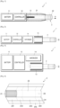
- FIGS. 1 through 3 are diagrams showing examples in which a cigarette is inserted into an aerosol generating device.
- the aerosol generating device 1 may include a battery 11, a controller 12, and a heater 13. Referring to FIGS. 2 and 3 , the aerosol generating device 1 may further include a vaporizer 14. Also, the cigarette 2 may be inserted into an inner space of the aerosol generating device 1.
- FIGS. 1 through 3 illustrate components of the aerosol generating device 1, which are related to the present embodiment. Therefore, it will be understood by one of ordinary skill in the art related to the present embodiment that other general-purpose components may be further included in the aerosol generating device 1, in addition to the components illustrated in FIGS. 1 through 3 .
- FIGS. 2 and 3 illustrate that the aerosol generating device 1 includes the heater 13. However, as necessary, the heater 13 may be omitted.
- FIG. 1 illustrates that the battery 11, the controller 12, and the heater 13 are arranged in series.
- FIG. 2 illustrates that the battery 11, the controller 12, the vaporizer 14, and the heater 13 are arranged in series.
- FIG. 3 illustrates that the vaporizer 14 and the heater 13 are arranged in parallel.
- the internal structure of the aerosol generating device 1 is not limited to the structures illustrated in FIGS. 1 through 3 . In other words, according to the design of the aerosol generating device 1, the battery 11, the controller 12, the heater 13, and the vaporizer 14 may be differently arranged.
- the aerosol generating device 1 may operate the heater 13 and/or the vaporizer 14 to generate an aerosol from the cigarette 2 and/or the vaporizer 14.
- the aerosol generated by the heater 13 and/or the vaporizer 14 is delivered to a user by passing through the cigarette 2.
- the aerosol generating device 1 may heat the heater 13.
- the battery 11 may supply power to be used for the aerosol generating device 1 to operate.
- the battery 11 may supply power to heat the heater 13 or the vaporizer 14, and may supply power for operating the controller 12.
- the battery 11 may supply power for operations of a display, a sensor, a motor, etc. mounted in the aerosol generating device 1.
- the controller 12 may generally control operations of the aerosol generating device 1. In detail, the controller 12 may control not only operations of the battery 11, the heater 13, and the vaporizer 14, but also operations of other components included in the aerosol generating device 1. Also, the controller 12 may check a state of each of the components of the aerosol generating device 1 to determine whether or not the aerosol generating device 1 is able to operate.
- the controller 12 may include at least one processor.
- a processor can be implemented as an array of a plurality of logic gates or can be implemented as a combination of a general-purpose microprocessor and a memory in which a program executable in the microprocessor is stored. It will be understood by one of ordinary skill in the art that the processor can be implemented in other forms of hardware.
- the heater 13 may be heated by the power supplied from the battery 11. For example, when the cigarette 2 is inserted into the aerosol generating device 1, the heater 13 may be located outside the cigarette 2. Thus, the heated heater 13 may increase a temperature of an aerosol generating material in the cigarette 2.
- the heater 13 may include an electro-resistive heater.
- the heater 13 may include an electrically conductive track, and the heater 13 may be heated when currents flow through the electrically conductive track.
- the heater 13 is not limited to the example described above and may include all heaters which may be heated to a desired temperature.
- the desired temperature may be pre-set in the aerosol generating device 1 or may be set as a temperature desired by a user.
- the heater 13 may include an induction heater.
- the heater 13 may include an electrically conductive coil for heating a cigarette in an induction heating method, and the cigarette may include a susceptor which may be heated by the induction heater.
- the heater 13 may include a tube-type heating element, a plate-type heating element, a needle-type heating element, or a rod-type heating element, and may heat the inside or the outside of the cigarette 2, according to the shape of the heating element.
- the aerosol generating device 1 may include a plurality of heaters 13.
- the plurality of heaters 13 may be inserted into the cigarette 2 or may be arranged outside the cigarette 2. Also, some of the plurality of heaters 13 may be inserted into the cigarette 2 and the others may be arranged outside the cigarette 2.
- the shape of the heater 13 is not limited to the shapes illustrated in FIGS. 1 through 3 and may include various shapes.
- the vaporizer 14 may generate an aerosol by heating a liquid composition and the generated aerosol may pass through the cigarette 2 to be delivered to a user.
- the aerosol generated via the vaporizer 14 may move along an air flow passage of the aerosol generating device 1 and the air flow passage may be configured such that the aerosol generated via the vaporizer 14 passes through the cigarette 2 to be delivered to the user.
- the vaporizer 14 may include a liquid storage, a liquid delivery element, and a heating element, but it is not limited thereto.
- the liquid storage, the liquid delivery element, and the heating element may be included in the aerosol generating device 1 as independent modules.
- the liquid storage may store a liquid composition.
- the liquid composition may be a liquid including a tobacco-containing material having a volatile tobacco flavor component, or a liquid including a non-tobacco material.
- the liquid storage may be detachable from the vaporizer 14 or may be formed integrally with the vaporizer 14.
- the liquid composition may include water, a solvent, ethanol, plant extract, spices, flavorings, or a vitamin mixture.
- the spices may include menthol, peppermint, spearmint oil, and various fruit-flavored ingredients, but are not limited thereto.
- the flavorings may include ingredients capable of providing various flavors or tastes to a user.
- Vitamin mixtures may be a mixture of at least one of vitamin A, vitamin B, vitamin C, and vitamin E, but are not limited thereto.
- the liquid composition may include an aerosol forming substance, such as glycerin and propylene glycol.
- the liquid delivery element may deliver the liquid composition of the liquid storage to the heating element.
- the liquid delivery element may be a wick such as cotton fiber, ceramic fiber, glass fiber, or porous ceramic, but is not limited thereto.
- the heating element is an element for heating the liquid composition delivered by the liquid delivery element.
- the heating element may be a metal heating wire, a metal hot plate, a ceramic heater, or the like, but is not limited thereto.
- the heating element may include a conductive filament such as nichrome wire and may be wound around the liquid delivery element. The heating element may be heated by a current supply and may transfer heat to the liquid composition in contact with the heating element, thereby heating the liquid composition. As a result, an aerosol may be generated.
- the vaporizer 14 may be referred to as a cartomizer or an atomizer, but it is not limited thereto.
- the aerosol generating device 1 may further include general-purpose components in addition to the battery 11, the controller 12, the heater 13, and the vaporizer 14.
- the aerosol generating device 1 may include a display capable of outputting visual information and/or a motor for outputting haptic information.
- the aerosol generating device 1 may include at least one sensor (e.g., a puff detecting sensor, a temperature detecting sensor, a cigarette insertion detecting sensor, etc.).
- the aerosol generating device 1 may be formed as a structure where, even when the cigarette 2 is inserted into the aerosol generating device 1, external air may be introduced or internal air may be discharged.
- the aerosol generating device 1 and an additional cradle may form together a system.
- the cradle may be used to charge the battery 11 of the aerosol generating device 1.
- the heater 13 may be heated when the cradle and the aerosol generating device 1 are coupled to each other.
- the cigarette 2 may be similar as a general combustive cigarette.
- the cigarette 2 may be divided into a first portion including an aerosol generating material and a second portion including a filter, etc.
- the second portion of the cigarette 2 may also include an aerosol generating material.
- an aerosol generating material made in the form of granules or capsules may be inserted into the second portion.
- the entire first portion may be inserted into the aerosol generating device 1, and the second portion may be exposed to the outside.
- only a portion of the first portion may be inserted into the aerosol generating device 1, or the entire first portion and a portion of the second portion may be inserted into the aerosol generating device 1.
- the user may puff aerosol while holding the second portion by the mouth of the user. In this case, the aerosol is generated by the external air passing through the first portion, and the generated aerosol passes through the second portion and is delivered to the user's mouth.
- the external air may flow into at least one air passage formed in the aerosol generating device 1.
- the opening and closing and/or a size of the air passage formed in the aerosol generating device 1 may be adjusted by the user. Accordingly, the amount of smoke and a smoking impression may be adjusted by the user.
- the external air may flow into the cigarette 2 through at least one hole formed in a surface of the cigarette 2.
- FIG. 4 illustrates an example of a cigarette.
- the cigarette 2 may include a tobacco rod 21 and a filter rod 22.
- the first portion 21 described above with reference to FIGS. 1 through 3 may include the tobacco rod 21, and the second portion 22 may include the filter rod 22.
- FIG. 4 illustrates that the filter rod 22 includes a single segment.
- the filter rod 22 is not limited thereto.
- the filter rod 22 may include a plurality of segments.
- the filter rod 22 may include a first segment configured to cool an aerosol and a second segment configured to filter a certain component included in the aerosol.
- the filter rod 22 may further include at least one segment configured to perform other functions.
- the cigarette 2 may be packaged by at least one wrapper 24.
- the wrapper 24 may have at least one hole through which external air may be introduced or internal air may be discharged.
- the cigarette 2 may be packaged by one wrapper.
- the cigarette 2 may be double-packaged by at least two wrappers 24.
- the tobacco rod 21 may be packaged by a first wrapper 241, and the filter rod 22 may be packaged by wrappers 242, 243, and 244. Then, the entire cigarette 2 may be packaged by another wrapper 245.
- each segment may be packaged individually by wrappers 242, 243, and 244.
- the tobacco rod 21 may include an aerosol generating material.
- the aerosol generating material may include at least one of glycerin, propylene glycol, ethylene glycol, dipropylene glycol, diethylene glycol, triethylene glycol, tetraethylene glycol, and oleyl alcohol, but it is not limited thereto.
- the tobacco rod 21 may include other additives, such as flavors, a wetting agent, and/or organic acid.
- the tobacco rod 21 may include a flavored liquid, such as menthol or a moisturizer, which is injected to the tobacco rod 21.
- the tobacco rod 21 may be manufactured in various forms.
- the tobacco rod 21 may be formed as a sheet or a strand.
- the tobacco rod 21 may be made out of pipe tobacco, which is formed of tiny bits cut from a tobacco sheet.
- the tobacco rod 21 may be surrounded by a heat conductive material.
- the heat-conducting material may be, but is not limited to, a metal foil such as aluminum foil.
- the heat conductive material surrounding the tobacco rod 21 may uniformly distribute heat transmitted to the tobacco rod 21, and thus, the heat conductivity applied to the tobacco rod may be increased and taste of the tobacco may be improved.
- the heat conductive material surrounding the tobacco rod 21 may function as a susceptor heated by the induction heater.
- the tobacco rod 21 may further include an additional susceptor, in addition to the heat conductive material surrounding the tobacco rod 21.
- the filter rod 22 may include a cellulose acetate filter. Shapes of the filter rod 22 are not limited.
- the filter rod 22 may include a cylinder-type rod or a tube-type rod having a hollow inside.
- the filter rod 22 may include a recess-type rod. When the filter rod 22 includes a plurality of segments, at least one of the plurality of segments may have a different shape.
- the filter rod 22 may include at least one capsule 23.
- the capsule 23 may generate a flavor or an aerosol.
- the capsule 23 may have a configuration in which a liquid containing a flavoring material is wrapped with a film.
- the capsule 23 may have a spherical or cylindrical shape, but is not limited thereto.
- the cigarette 3 may further include a front-end plug 33.
- the front-end plug 33 may be located on a side of the tobacco rod 42, the side not facing the filter rod 32.
- the front-end plug 33 may prevent the tobacco rod 31 from falling out and prevent a liquefied aerosol from flowing into the aerosol generating device 1 from the tobacco rod 31, during smoking.
- the filter rod 32 may include a first segment 321 and second segment 322.
- the first segment 321 can correspond to a first segment of a filter rod 22 of Fig. 4
- the second segment 322 can correspond to a third segment of a filter rod 22 of Fig. 4 .
- the diameter and total length of the cigarette 3 can correspond to the diameter and total length of the cigarette 2 of Fig. 4 .
- the length of the front-end plug 33 may be about 7 mm
- the length of the tobacco rod 31 may be about 15 mm
- the length of the first segment 321 may be about 12 mm
- the length of the second segment 322 may be about 14 mm, but it is not limited to this.
- the cigarette 3 may be packaged by at least one wrapper 35.
- the wrapper 35 may have at least one hole through which external air may be introduced or internal air may be discharged.
- the front-end plug33 may be packaged by a first wrapper 351, and the tobacco rod 31 may be packaged by a second wrapper 352, and the first segment 321 may be packaged by a third wrapper 321, and the second segment 322 may be packaged by a fourth wrapper 354.
- the entire cigarette 3 may be packaged by a fifth wrapper 355.
- the fifth wrapper 355 may have at least one hole 36.
- the hole 36 may be formed in an area surrounding the tobacco rod 31, but is not limited thereto.
- the hole 36 may serve to transfer heat formed by the heater 13 shown in Fig. 2 and Fig. 3 to the inside of the tobacco rod 31.
- the second segment 322 may include at least one capsule 34.
- the capsule 34 may generate a flavor or an aerosol.
- the capsule 34 may have a configuration in which a liquid containing a flavoring material is wrapped with a film.
- the capsule 34 may have a spherical or cylindrical shape, but is not limited thereto.
- FIG. 6 is a block diagram of an aerosol generating device according to an embodiment.
- an aerosol generating device 600 may include a memory 610, a temperature sensor 620, a battery 630, a heater 640, a user interface 650, and a controller 660.
- the battery 630 of FIG. 6 may correspond to the battery 11 of FIGS. 1 to 3
- the heater 640 of FIG. 6 may correspond to the heater 13 of FIGS. 1 to 3 . Therefore, redundant descriptions thereof are omitted.
- the heater 640 may heat an aerosol generating substrate.
- the aerosol generating substrate may be the cigarette 2 of FIGS. 1 to 3 .
- the temperature sensor 620 may detect a temperature of the heater 640. In one embodiment, the temperature sensor 620 may detect the temperature of the heater 640 in real time, convert temperature information into a digital signal, and output the digital signal. The temperature sensor 620 may transmit the digital signal to the controller 660.
- the controller 660 may include a pulse width modulator 661, a monitor 662, a filter 663, and a puff determination unit 664.
- the controller 660 may control power supplied to the heater 640 through a power signal.
- the power signal may be a pulse width modulation (PWM) signal.
- PWM pulse width modulation
- the power signal in the form of PWM may be output by the pulse width modulator 661.
- the pulse width modulator 661 may control the power supplied from the battery 630 to the heater 640 by modulating a duty (i.e., by adjusting a duty ratio) of a DC pulse.
- the pulse width modulator 661 may include a switching element and may modulate the duty of the DC pulse by adjusting an opening/closing cycle or an opening/closing ratio of the switching element.
- the controller 660 may receive temperature information from the temperature sensor 620 and control the power supplied to the heater 640 based on the temperature information.
- the controller 660 may control the power supplied to the heater 640 such that a temperature of the heater 640 is within a preset temperature range.
- the controller 660 may control the power supplied to the heater 640 such that the temperature of the heater 640 is heated in a range of 100°C to 230°C.
- the preset range is not limited to the above-described example and may be appropriately set by considering a vaporization temperature of the aerosol generating substrate.
- the controller 660 may increase a duty value of a power signal to compensate for a decrease in temperature of the heater 640. In other words, when the temperature of the heater 640 is decreased by a user's puff, the controller 660 may increase the duty value of the power signal such that the temperature of the heater 640 is within a preset range.
- the controller 660 may detect the user's puff based on the increased duty ratio. Specifically, the monitor 662 may monitor a power signal output from the pulse width modulator 661. The monitor 622 may transmit the monitored power signal to the filter 663.
- the filter 663 may perform band-pass filtering on the power signal.
- the filter 663 may include a band-pass filter (BPF).
- BPF band-pass filter
- the BPF may be a digital filter.
- the filter 663 may filter the power signal through band-pass filtering, thereby removing a decrease tendency (which may be expressed as an envelope) of the power signal over time and may output a deviation value of the power signal over time.
- the BPF may include a first low-pass filter 663a (see FIG. 10A ) and a second low-pass filter 663b (see FIG. 10A ).
- a calculation amount of a low-pass filter (LPF) is less than a calculation amount of a high-pass filter (HPF), and thus, when a BPF is embodied with LPFs, a filter calculation speed may be significantly increased.
- Equation 1 H(s) is a transfer function, and ⁇ is a time constant of a LPF.
- a discrete output signal yn for a discrete input signal xn may be represented as follows.
- a cutoff frequency of the LPF may be determined by a time constant ⁇
- the first LPF 663a may filter a power signal by using a first time constant ⁇ 1
- the second LPF 663b may filter the power signal by using a second time constant ⁇ 2.
- a power signal of a preset band may be obtained by subtracting a power signal passing through the second LPF 663b from a power signal passing through the first LPF 663a.
- a center frequency may be determined based on an average puff time of a user.
- the center frequency may be set based on an average puff time of a general user as stipulated by the Health Canada. For example, an average puff time of a user may be 2 seconds.
- the controller 660 may convert an average puff time of a user into a frequency. Accordingly, the average puff time may be converted into an average puff frequency. For example, when the average puff time is 2 seconds, the average puff frequency may be converted to 0.125 Hz according to an experiment.
- the controller 660 may set the average puff frequency as a center frequency of a BPF. For example, when an average puff time of a user is 2 seconds, the center frequency may be set to 0.125 Hz.
- the controller 660 may set a puff recognition time based on the average puff time of the user. For example, when the average puff time of the user is 2 seconds, the controller 660 may set 1 second to 3 seconds as the puff recognition time.
- the controller 660 may convert the puff recognition time into a frequency.
- the puff recognition time may mean a time for effectively recognizing the user's puff. Accordingly, the puff recognition time may be converted into a puff recognition frequency. For example, when the puff recognition time is 1 second to 3 seconds, the puff recognition frequency may be set to 1/12 (about 0.083) Hz to 0.25 Hz according to an experiment.
- the controller 660 may set a lower cutoff frequency and a higher cutoff frequency of a BPF based on the puff recognition frequency. For example, when the puff recognition frequency is 1/12 (about 0.083) Hz to 0.25 Hz, the controller 660 may set the lower cutoff frequency to 1/12 (0.083) Hz and set the higher cutoff frequency to 0.25Hz.
- the filter 663 may transmit the filtered power signal to the puff determination unit 664.
- the puff determination unit 664 may detect a user's puff based on the filtered power signal.
- the puff determination unit 664 may compare the filtered power signal with a preset threshold. In addition, the puff determination unit 664 may determine the filtered power signal greater than or equal to the preset threshold as the user's puff.
- a threshold may be set based on an average value of the maximum value and the minimum value of the power signal or the filtered power signal in each puff period but is not limited thereto, and any value between the maximum value and the minimum value of the filtered power signal may be selected as the threshold.
- the user interface 650 may provide information on a state of the aerosol generating device 600 to a user.
- the user interface 650 may include various interfaces such as a display or a lamp that outputs visual information, a motor that outputs tactile information, a speaker that outputs sound information, a terminal for data communication with an input/output (I/O) interface (for example, a button or a touch screen) that receives information input from a user or outputs information to the user or for receiving charging power, and a communication interfacing module for performing wireless communication (for example, WI-FI, WI-FI Direct, Bluetooth, near-field communication (NFC), or so on) with an external device.
- I/O input/output
- a communication interfacing module for performing wireless communication (for example, WI-FI, WI-FI Direct, Bluetooth, near-field communication (NFC), or so on) with an external device.
- the aerosol generating device 600 may selectively include only some of the examples of the various user interfaces 650 described above.
- the memory 610 is hardware that stores various types of data processed in the aerosol generating device 600 and may store data processed by the controller 660 and data to be processed thereby.
- the memory 610 may include various types of memories such as random access memory (RAM) such as dynamic random access memory (DRAM) or static random access memory (SRAM), read-only memory (ROM), and electrically erasable programmable read-only memory (EEPROM).
- RAM random access memory
- DRAM dynamic random access memory
- SRAM static random access memory
- ROM read-only memory
- EEPROM electrically erasable programmable read-only memory
- an internal structure of the aerosol generating device 600 is not limited to the structure illustrated in FIG. 6 .
- Those skilled in the art relating to the present embodiment will be appreciate that some of the hardware configurations illustrated in FIG. 6 may be omitted or a new configuration may be added thereto depending on the design of the aerosol generating device 600.
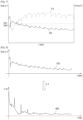
- FIG. 7 is a view illustrating a power control method according to a heater temperature.
- FIG. 7 illustrates a temperature sensing value 710 of the temperature sensor 620 and a power signal 720 of the controller 660.
- an x-axis denotes a time
- a y-axis denotes a duty and a temperature.
- a duty value is plotted with a scale factor of four for comparison with the temperature sensing value 710.
- the controller 660 may control power supplied to the heater 640 such that a temperature of the heater 640 is within a preset temperature range.
- the controller 660 may control the power supplied to the heater 640 such that the temperature of the heater 640 is heated within a range of 100°C to 230°C.
- the preset temperature range is not limited to the above-described example and may be appropriately set by considering vaporization temperature of the aerosol generating substrate.
- the controller 660 may increase a duty value of the power signal 720 to compensate for the decrease in temperature of the heater 640.
- the controller 660 may increase the duty value of the power signal 720 such that the temperature of the heater 640 is within the preset temperature range.
- the controller 660 may detect the user's puff based on the increased duty value (i.e., based on the increased duty ratio).
- the power signal 720 of FIG. 7 has a small difference between the maximum value and the minimum value of the duty in one period of the puff.
- the power signal 720 of FIG. 7 has a large variation of the maximum values of duties in each puff period.
- the controller 660 may not use a fixed threshold to detect a user's puff. Instead, the controller 660 may set different thresholds Dth1, Dth2, ... in each puff period. In this case, there is a problem that a rapid puff detection may not be made due to an increase in calculation amount of the controller 660. In addition, there is a problem that the controller 660 may not accurately detect the user's puff because a difference between the maximum value and the minimum value of the duty is small within one period of the puff.
- an embodiment may adopt a digital filter and detects a user's puff based on the power signal to which the digital filter is applied.
- FIG. 8 illustrates a frequency-converted power signal
- FIG. 9 is a diagram illustrating a method of operating a BPF
- FIGS. 10A and 10B illustrate a method of implementing the BPF
- FIG. 11 is a diagram illustrating a method of comparing a filtered power signal and a preset threshold.
- the controller 660 may convert the power signal 720 in a time domain into a power signal 820 in a frequency domain.
- the controller 660 may convert the power signal 720 in a time domain into the power signal 820 in a frequency domain by using a Fourier Transform (FT), a Fast Fourier Transform (FFT), a Discrete Fourier Transform (DFT), and so on.
- FT Fourier Transform
- FFT Fast Fourier Transform
- DFT Discrete Fourier Transform
- the method of converting a frequency domain is not limited to the above-described examples.
- the filter 663 may band-pass-filter the power signal 820 in the frequency domain. To this end, the filter 663 may include a BPF 910.
- a center frequency fo of the BPF 910 may be set based on an average puff time of a user. For example, when the average puff time of the user is 2 seconds, the center frequency fo may be set to 0.125 Hz according to an experiment.
- a lower cutoff frequency fL and a higher cutoff frequency fH of the BPF 910 may be set based on a preset puff recognition time. For example, when the average puff time of the user is 2 seconds, the puff recognition time may be set to 1 to 3 seconds. In addition, when the puff recognition time is 1 second to 3 seconds, the lower cutoff frequency may be set to 1/12 (0.083) Hz, and the higher cutoff frequency may be set to 0.25Hz. Accordingly, a bandwidth BW of the BPF 910 may be set to 1/6 (0.167) Hz.
- the BPF 910 may include the first LPF 663a and the second LPF 663b as illustrated in FIGS. 10A to 10B .
- the filter 663 may include the first LPF 663a and the second LPF 663b. Unlike FIG. 10B , pass gains of the first LPF 663a and the second LPF 663b may be the same.
- the first LPF 663a may remove frequencies higher than or equal to a first cutoff frequency fc1.
- the second LPF 663b may remove frequencies higher than or equal to a second cutoff frequency fc2.
- a difference between the first cutoff frequency fc1 and the second cutoff frequency fc2 may correspond to the bandwidth BW of the BPF 910.
- the first LPF 663a may output a first filtering signal Y1 by filtering a power signal.
- the second LPF 663b may output a second filtering signal Y2 by filtering a power signal.
- the filter 663 may output a third filtering signal Y3 by subtracting the second filtering signal Y2 from the first filtering signal Y1.
- the third filtering signal Y3 may be a band-pass-filtered power signal.
- FIG. 11 shows an example of a time domain signal corresponding to the band-pass-filtered power signal Y3.
- a filtered power signal 1110 of FIG. 11 has a large difference between a maximum value and a minimum value of a duty within one period of a puff.
- the filtered power signal 1110 of FIG. 11 has a small variation of maximum values of duties obtained in each puff period. Accordingly, the controller 660 may use a fixed threshold value Dth to detect a user's puff. In addition, since there is the large difference between the maximum value and the minimum value of the duty within one period of a puff, the controller 660 may accurately detect the user's puff.
- the puff determination unit 664 may compare the filtered power signal with the preset threshold Dth, and determine that a user's puff has occurred when the filtered power signal is greater than or equal to the preset threshold.
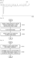
- FIG. 12 is a flowchart illustrating an operating method of an aerosol generating device according to an embodiment.
- the controller 660 may control power supplied to the heater 640 through a power signal to heat a temperature of the heater 640 within a preset range.
- the power signal may be a pulse width modulation signal.
- the controller 660 may control power supplied from the battery 630 to the heater 640 by modulating a duty of a DC pulse.
- the pulse width modulator 661 may include a switching element and may modulate the duty of the DC pulse by adjusting an opening/closing cycle or an opening/closing ratio of the switching element.
- the controller 660 may receive temperature information from the temperature sensor 620 and control the power supplied to the heater 640 based on the temperature information.
- the controller 660 may control the power supplied to the heater 640 such that a temperature of the heater 640 is within a preset temperature range.
- step S1220 the controller 660 may filter a power signal.
- the controller 660 may band-pass-filter the power signal. To this end, the controller 660 may include a BPF.
- the BPF may be a digital filter.
- a center frequency of the controller 660 may be set based on an average puff time of a user. For example, when the average puff time of the user is 2 seconds, and the center frequency may be set to 0.125 Hz according to an experiment.
- the controller 660 may set a lower cutoff frequency and a higher cutoff frequency of the BPF based on a preset puff recognition time. For example, when the average puff time of the user is 2 seconds, the puff recognition time may be set to 1 second to 3 seconds. In addition, when the puff recognition time is 1 second to 3 seconds, the lower cutoff frequency may be set to 1/12 (0.083) Hz, and the higher cutoff frequency may be set to 0.25Hz according to an experiment. Accordingly, the bandwidth BW of the BPF 910 may be set to 1/6 (0.167) Hz.
- step S1230 the controller 660 may detect a user's puff based on the filtered power signal.
- the controller 660 may detect the user's puff based on a fixed threshold. The controller 660 may determine that the user's puff has occurred when the filtered power signal is greater than or equal to a preset threshold.
- the controller 660 may count the user's puff. In addition, the controller 660 may control internal components of the aerosol generating device 600 based on the counted number of the user's puffs. For example, the controller 660 may display the number of remaining puffs via the user interface 650. However, this is only an example, and the operation of the controller 660 based on the user's puff is not limited thereto.
- FIG. 13 is a diagram illustrating the method of detecting the puff.
- the controller 660 may compare the filtered power signal with the preset threshold.
- the controller 660 may determine that the user's puff has occurred when the filtered power signal is greater than or equal to a threshold. As aforementioned, since the filtered power signal according to the embodiments has a large difference between a maximum value and a minimum value of a duty within one period of a puff, the controller 660 may accurately detect the user's puff.
- At least one of the components, elements, modules or units may be embodied as various numbers of hardware, software and/or firmware structures that execute respective functions described above, according to an exemplary embodiment.
- at least one of these components may use a direct circuit structure, such as a memory, a processor, a logic circuit, a look-up table, etc. that may execute the respective functions through controls of one or more microprocessors or other control apparatuses.
- At least one of these components may be specifically embodied by a module, a program, or a part of code, which contains one or more executable instructions for performing specified logic functions, and executed by one or more microprocessors or other control apparatuses.
- at least one of these components may include or may be implemented by a processor such as a central processing unit (CPU) that performs the respective functions, a microprocessor, or the like. Two or more of these components may be combined into one single component which performs all operations or functions of the combined two or more components. Also, at least part of functions of at least one of these components may be performed by another of these components.
- a bus is not illustrated in the above block diagrams, communication between the components may be performed through the bus. Functional aspects of the above exemplary embodiments may be implemented in algorithms that execute on one or more processors.
- the components represented by a block or processing steps may employ any number of related art techniques for electronics configuration, signal processing and/or control, data processing and the like.
Landscapes
- Health & Medical Sciences (AREA)
- Engineering & Computer Science (AREA)
- Life Sciences & Earth Sciences (AREA)
- General Health & Medical Sciences (AREA)
- Veterinary Medicine (AREA)
- Hematology (AREA)
- Biomedical Technology (AREA)
- Animal Behavior & Ethology (AREA)
- Anesthesiology (AREA)
- Public Health (AREA)
- Heart & Thoracic Surgery (AREA)
- Bioinformatics & Cheminformatics (AREA)
- Pulmonology (AREA)
- Biophysics (AREA)
- Control Of Resistance Heating (AREA)
- Devices For Medical Bathing And Washing (AREA)
- Thermotherapy And Cooling Therapy Devices (AREA)
Claims (10)
- Aerosolerzeugungsvorrichtung (1, 600), die Folgendes umfasst:eine Heizeinrichtung (13, 640), die konfiguriert ist, ein Aerosolerzeugungssubstrat (2) zu erhitzen;einen Temperatursensor (620), der konfiguriert ist, eine Temperatur der Heizeinrichtung (13, 640) zu detektieren; undeine Steuereinheit (12, 660), die konfiguriert ist, Leistung, die der Heizeinrichtung (13, 640) zugeführt wird, durch ein Leistungssignal zu steuern, so dass die Heizeinrichtung (13, 640) innerhalb eines zuvor eingestellten Temperaturbereichs geheizt wird, das Leistungssignal zu filtern und einen Zug eines Benutzers auf der Basis des gefilterten Leistungssignals zu detektieren.
- Aerosolerzeugungsvorrichtung (1, 600) nach Anspruch 1, wobei das Leistungssignal ein Pulsbreitenmodulationssignal ist.
- Aerosolerzeugungsvorrichtung (1, 600) nach Anspruch 2, wobei die Steuereinheit (12, 600) einen Tastgradwert des Pulsbreitenmodulationssignals in Reaktion auf eine Abnahme der Temperatur der Heizeinrichtung (13, 640) erhöht.
- Aerosolerzeugungsvorrichtung (1, 600) nach Anspruch 1, wobei die Steuereinheit (12, 600) ein Bandpassfilter umfasst, das konfiguriert ist, das Leistungssignal zu filtern.
- Aerosolerzeugungsvorrichtung (1, 600) nach Anspruch 4, wobei eine Mittenfrequenz des Bandpassfilters auf der Basis einer mittleren Zugzeit eines Benutzers eingestellt wird.
- Aerosolerzeugungsvorrichtung (1, 600) nach Anspruch 5, wobei die mittlere Zugzeit 2 Sekunden beträgt.
- Aerosolerzeugungsvorrichtung (1, 600) nach Anspruch 4, wobei eine Mittenfrequenz des Bandpassfilters 0,125 Hz beträgt, eine untere Grenzfrequenz des Bandpassfilters 0,083 Hz beträgt und eine obere Grenzfrequenz des Bandpassfilters 0,25 Hz beträgt.
- Aerosolerzeugungsvorrichtung (1, 600) nach Anspruch 4, wobei das Bandpassfilter ein erstes Tiefpassfilter und ein zweites Tiefpassfilter umfasst.
- Aerosolerzeugungsvorrichtung (1, 600) nach Anspruch 8, wobei eine erste Grenzfrequenz des ersten Tiefpassfilters 0,25 Hz beträgt und eine zweite Grenzfrequenz des zweiten Tiefpassfilters 0,083 Hz beträgt.
- Aerosolerzeugungsvorrichtung (1, 600) nach Anspruch 1, wobei die Steuereinheit (12, 660) das gefilterte Leistungssignal mit einem zuvor eingestellten Schwellenwert vergleicht und basierend darauf, dass das gefilterte Leistungssignal gleich dem Schwellenwert oder größer ist, feststellt, dass der Zug eines Benutzers erfolgt ist.
Applications Claiming Priority (2)
| Application Number | Priority Date | Filing Date | Title |
|---|---|---|---|
| KR1020200086433A KR102535303B1 (ko) | 2020-07-13 | 2020-07-13 | 에어로졸 생성 장치 |
| PCT/KR2021/008857 WO2022014979A1 (en) | 2020-07-13 | 2021-07-12 | Aerosol generating device |
Publications (3)
| Publication Number | Publication Date |
|---|---|
| EP4048102A1 EP4048102A1 (de) | 2022-08-31 |
| EP4048102A4 EP4048102A4 (de) | 2022-12-07 |
| EP4048102B1 true EP4048102B1 (de) | 2025-02-12 |
Family
ID=79555610
Family Applications (1)
| Application Number | Title | Priority Date | Filing Date |
|---|---|---|---|
| EP21841302.9A Active EP4048102B1 (de) | 2020-07-13 | 2021-07-12 | Aerosolerzeugungsvorrichtung |
Country Status (8)
| Country | Link |
|---|---|
| US (1) | US12495835B2 (de) |
| EP (1) | EP4048102B1 (de) |
| JP (1) | JP7324372B2 (de) |
| KR (1) | KR102535303B1 (de) |
| CN (1) | CN114867376A (de) |
| PL (1) | PL4048102T3 (de) |
| UA (1) | UA129433C2 (de) |
| WO (1) | WO2022014979A1 (de) |
Families Citing this family (5)
| Publication number | Priority date | Publication date | Assignee | Title |
|---|---|---|---|---|
| US12520880B2 (en) | 2021-01-18 | 2026-01-13 | Altria Client Services Llc | Heat-not-burn (HNB) aerosol-generating devices including energy based heater control, and methods of controlling a heater |
| WO2023068790A1 (en) | 2021-10-19 | 2023-04-27 | Kt&G Corporation | Aerosol-generating device and operation method thereof |
| US12550942B2 (en) | 2022-09-19 | 2026-02-17 | Altria Client Services Llc | Session control system |
| CN118923956A (zh) * | 2023-05-09 | 2024-11-12 | 思摩尔国际控股有限公司 | 气溶胶产生装置及其抽吸检测方法 |
| CN117413983B (zh) * | 2023-10-16 | 2024-09-20 | 深圳市斯科尔科技股份有限公司 | 雾化设备及其电源管理方法和存储介质 |
Citations (1)
| Publication number | Priority date | Publication date | Assignee | Title |
|---|---|---|---|---|
| EP2797448B1 (de) * | 2011-12-30 | 2016-07-20 | Philip Morris Products S.a.s. | Aerosolerzeugende vorrichtung mit luftstromdetektion |
Family Cites Families (15)
| Publication number | Priority date | Publication date | Assignee | Title |
|---|---|---|---|---|
| EP1989946A1 (de) | 2007-05-11 | 2008-11-12 | Rauchless Inc. | Rauchartikel, Ladevorrichtung und Verwendungsverfahren |
| US8389908B2 (en) * | 2009-02-10 | 2013-03-05 | Honeywell International Inc. | Systems and methods for sourcing a heater |
| US9736887B2 (en) * | 2011-10-21 | 2017-08-15 | Getac Technology Corporation | Method and device for heating electronic component and electronic apparatus using the same |
| US10492528B2 (en) | 2015-08-11 | 2019-12-03 | Altria Client Services Llc | Power supply section configuration for an electronic vaping device and electronic vaping device |
| GB201517088D0 (en) | 2015-09-28 | 2015-11-11 | Nicoventures Holdings Ltd | Electronic aerosol provision systems and methods |
| GB201517087D0 (en) | 2015-09-28 | 2015-11-11 | Nicoventures Holdings Ltd | Vaping policy alert system and method |
| US10757973B2 (en) * | 2016-07-25 | 2020-09-01 | Fontem Holdings 1 B.V. | Electronic cigarette with mass air flow sensor |
| CN110545682A (zh) | 2017-04-11 | 2019-12-06 | 韩国烟草人参公社 | 提供基于抽吸识别的适应性反馈的气溶胶生成设备及方法 |
| JP6680951B2 (ja) * | 2017-04-24 | 2020-04-15 | 日本たばこ産業株式会社 | エアロゾル生成装置並びにエアロゾル生成装置の制御方法及びプログラム |
| KR102105548B1 (ko) * | 2017-09-26 | 2020-04-28 | 주식회사 케이티앤지 | 에어로졸 생성장치의 피드백 제어기능을 구현하는 방법 및 그 에어로졸 생성장치 |
| KR20190051785A (ko) * | 2017-11-06 | 2019-05-15 | 주식회사 케이티앤지 | 에어로졸 생성장치를 통해 흡연감을 제공하는 방법 및 그 에어로졸 생성장치 |
| KR102372336B1 (ko) * | 2018-02-06 | 2022-03-10 | 주식회사 케이티앤지 | 에어로졸을 생성하는 장치 및 방법 |
| CN109283867A (zh) * | 2018-08-24 | 2019-01-29 | 深圳市合元科技有限公司 | 一种开关控制电路、开关控制方法及电子烟 |
| KR102199795B1 (ko) | 2018-11-19 | 2021-01-07 | 주식회사 케이티앤지 | 일정주파수 이하의 신호로 에어로졸 생성장치의 히터의 전력을 제어하는 방법 및 그 에어로졸 생성장치 |
| PL3958696T3 (pl) * | 2019-04-23 | 2024-05-13 | Philip Morris Products S.A. | Urządzenie do wytwarzania aerozolu z wykrywaniem zaciągnięć i sposobem do wykrywania zaciągnięć |
-
2020
- 2020-07-13 KR KR1020200086433A patent/KR102535303B1/ko active Active
-
2021
- 2021-07-12 US US17/784,818 patent/US12495835B2/en active Active
- 2021-07-12 WO PCT/KR2021/008857 patent/WO2022014979A1/en not_active Ceased
- 2021-07-12 EP EP21841302.9A patent/EP4048102B1/de active Active
- 2021-07-12 JP JP2022539262A patent/JP7324372B2/ja active Active
- 2021-07-12 CN CN202180007586.2A patent/CN114867376A/zh active Pending
- 2021-07-12 PL PL21841302.9T patent/PL4048102T3/pl unknown
- 2021-07-12 UA UAA202202180A patent/UA129433C2/uk unknown
Patent Citations (1)
| Publication number | Priority date | Publication date | Assignee | Title |
|---|---|---|---|---|
| EP2797448B1 (de) * | 2011-12-30 | 2016-07-20 | Philip Morris Products S.a.s. | Aerosolerzeugende vorrichtung mit luftstromdetektion |
Also Published As
| Publication number | Publication date |
|---|---|
| US12495835B2 (en) | 2025-12-16 |
| CN114867376A (zh) | 2022-08-05 |
| WO2022014979A1 (en) | 2022-01-20 |
| JP7324372B2 (ja) | 2023-08-09 |
| JP2023508207A (ja) | 2023-03-01 |
| UA129433C2 (uk) | 2025-04-23 |
| KR102535303B1 (ko) | 2023-05-22 |
| EP4048102A1 (de) | 2022-08-31 |
| KR20220008167A (ko) | 2022-01-20 |
| CA3157625A1 (en) | 2022-01-20 |
| PL4048102T3 (pl) | 2025-06-09 |
| EP4048102A4 (de) | 2022-12-07 |
| US20230000166A1 (en) | 2023-01-05 |
Similar Documents
| Publication | Publication Date | Title |
|---|---|---|
| EP4048102B1 (de) | Aerosolerzeugungsvorrichtung | |
| US11925215B2 (en) | Aerosol generating device and method of controlling the same | |
| US20250338889A1 (en) | Aerosol generating device and operation method thereof | |
| EP3817596B1 (de) | Aerosolerzeugungsvorrichtung und verfahren zur schätzung der batterielebensdauer dafür | |
| EP3818868B1 (de) | Aerosolerzeugungsvorrichtung und verfahren zur steuerung davon | |
| EP3883411B1 (de) | Aerosolerzeugungsvorrichtung und betriebsverfahren dafür | |
| EP3704964B1 (de) | Aerosolerzeugungsvorrichtung | |
| EP3893680B1 (de) | Aerosolerzeugungsvorrichtung und betriebsverfahren dafür | |
| EP3818874A1 (de) | Verfahren zur steuerung der leistung eines erhitzers einer kontinuierlich verwendbaren aerosolerzeugungsvorrichtung sowie aerosolerzeugungsvorrichtung dafür | |
| EP3954237B1 (de) | Aerosolerzeugungsvorrichtung und betriebsverfahren dafür | |
| EP3818878A1 (de) | Verfahren zur steuerung der elektrischen leistung des erhitzers einer aerosolerzeugungsvorrichtung mit einem signal einer bestimmten frequenz oder weniger und aerosolerzeugungsvorrichtung mit verwendung davon | |
| KR102424390B1 (ko) | 에어로졸 생성 장치 및 그의 동작 방법 | |
| EP4088600A1 (de) | Aerosolerzeugungsvorrichtung zur bestimmung, ob ein aerosolerzeugungsartikel überfeuchteten zustand ist | |
| JP2024518113A (ja) | 巻タバコタイプに基づいてエアロゾルを生成する方法及び装置 | |
| CA3157625C (en) | Aerosol generating device with puff detection | |
| RU2811156C1 (ru) | Устройство для генерирования аэрозоля | |
| JP7681730B2 (ja) | 充電情報を出力する方法及び装置 | |
| CN118119308A (zh) | 气溶胶产生装置及其操作方法 |
Legal Events
| Date | Code | Title | Description |
|---|---|---|---|
| STAA | Information on the status of an ep patent application or granted ep patent |
Free format text: STATUS: THE INTERNATIONAL PUBLICATION HAS BEEN MADE |
|
| PUAI | Public reference made under article 153(3) epc to a published international application that has entered the european phase |
Free format text: ORIGINAL CODE: 0009012 |
|
| STAA | Information on the status of an ep patent application or granted ep patent |
Free format text: STATUS: REQUEST FOR EXAMINATION WAS MADE |
|
| 17P | Request for examination filed |
Effective date: 20220525 |
|
| AK | Designated contracting states |
Kind code of ref document: A1 Designated state(s): AL AT BE BG CH CY CZ DE DK EE ES FI FR GB GR HR HU IE IS IT LI LT LU LV MC MK MT NL NO PL PT RO RS SE SI SK SM TR |
|
| A4 | Supplementary search report drawn up and despatched |
Effective date: 20221109 |
|
| RIC1 | Information provided on ipc code assigned before grant |
Ipc: A61M 15/06 20060101ALI20221103BHEP Ipc: A61M 11/04 20060101ALI20221103BHEP Ipc: A24F 40/57 20200101ALI20221103BHEP Ipc: A61M 15/00 20060101ALI20221103BHEP Ipc: A24F 40/51 20200101ALI20221103BHEP Ipc: A24F 40/50 20200101AFI20221103BHEP |
|
| P01 | Opt-out of the competence of the unified patent court (upc) registered |
Effective date: 20230526 |
|
| DAV | Request for validation of the european patent (deleted) | ||
| DAX | Request for extension of the european patent (deleted) | ||
| GRAP | Despatch of communication of intention to grant a patent |
Free format text: ORIGINAL CODE: EPIDOSNIGR1 |
|
| STAA | Information on the status of an ep patent application or granted ep patent |
Free format text: STATUS: GRANT OF PATENT IS INTENDED |
|
| INTG | Intention to grant announced |
Effective date: 20240905 |
|
| GRAS | Grant fee paid |
Free format text: ORIGINAL CODE: EPIDOSNIGR3 |
|
| GRAA | (expected) grant |
Free format text: ORIGINAL CODE: 0009210 |
|
| STAA | Information on the status of an ep patent application or granted ep patent |
Free format text: STATUS: THE PATENT HAS BEEN GRANTED |
|
| AK | Designated contracting states |
Kind code of ref document: B1 Designated state(s): AL AT BE BG CH CY CZ DE DK EE ES FI FR GB GR HR HU IE IS IT LI LT LU LV MC MK MT NL NO PL PT RO RS SE SI SK SM TR |
|
| REG | Reference to a national code |
Ref country code: GB Ref legal event code: FG4D |
|
| REG | Reference to a national code |
Ref country code: CH Ref legal event code: EP |
|
| REG | Reference to a national code |
Ref country code: DE Ref legal event code: R096 Ref document number: 602021026145 Country of ref document: DE |
|
| REG | Reference to a national code |
Ref country code: IE Ref legal event code: FG4D |
|
| REG | Reference to a national code |
Ref country code: NL Ref legal event code: MP Effective date: 20250212 |
|
| PG25 | Lapsed in a contracting state [announced via postgrant information from national office to epo] |
Ref country code: RS Free format text: LAPSE BECAUSE OF FAILURE TO SUBMIT A TRANSLATION OF THE DESCRIPTION OR TO PAY THE FEE WITHIN THE PRESCRIBED TIME-LIMIT Effective date: 20250512 |
|
| PG25 | Lapsed in a contracting state [announced via postgrant information from national office to epo] |
Ref country code: FI Free format text: LAPSE BECAUSE OF FAILURE TO SUBMIT A TRANSLATION OF THE DESCRIPTION OR TO PAY THE FEE WITHIN THE PRESCRIBED TIME-LIMIT Effective date: 20250212 |
|
| PGFP | Annual fee paid to national office [announced via postgrant information from national office to epo] |
Ref country code: PL Payment date: 20250627 Year of fee payment: 5 |
|
| PG25 | Lapsed in a contracting state [announced via postgrant information from national office to epo] |
Ref country code: ES Free format text: LAPSE BECAUSE OF FAILURE TO SUBMIT A TRANSLATION OF THE DESCRIPTION OR TO PAY THE FEE WITHIN THE PRESCRIBED TIME-LIMIT Effective date: 20250212 |
|
| REG | Reference to a national code |
Ref country code: LT Ref legal event code: MG9D |
|
| PG25 | Lapsed in a contracting state [announced via postgrant information from national office to epo] |
Ref country code: NO Free format text: LAPSE BECAUSE OF FAILURE TO SUBMIT A TRANSLATION OF THE DESCRIPTION OR TO PAY THE FEE WITHIN THE PRESCRIBED TIME-LIMIT Effective date: 20250512 Ref country code: IS Free format text: LAPSE BECAUSE OF FAILURE TO SUBMIT A TRANSLATION OF THE DESCRIPTION OR TO PAY THE FEE WITHIN THE PRESCRIBED TIME-LIMIT Effective date: 20250612 |
|
| PG25 | Lapsed in a contracting state [announced via postgrant information from national office to epo] |
Ref country code: NL Free format text: LAPSE BECAUSE OF FAILURE TO SUBMIT A TRANSLATION OF THE DESCRIPTION OR TO PAY THE FEE WITHIN THE PRESCRIBED TIME-LIMIT Effective date: 20250212 |
|
| PG25 | Lapsed in a contracting state [announced via postgrant information from national office to epo] |
Ref country code: HR Free format text: LAPSE BECAUSE OF FAILURE TO SUBMIT A TRANSLATION OF THE DESCRIPTION OR TO PAY THE FEE WITHIN THE PRESCRIBED TIME-LIMIT Effective date: 20250212 |
|
| PG25 | Lapsed in a contracting state [announced via postgrant information from national office to epo] |
Ref country code: LV Free format text: LAPSE BECAUSE OF FAILURE TO SUBMIT A TRANSLATION OF THE DESCRIPTION OR TO PAY THE FEE WITHIN THE PRESCRIBED TIME-LIMIT Effective date: 20250212 Ref country code: PT Free format text: LAPSE BECAUSE OF FAILURE TO SUBMIT A TRANSLATION OF THE DESCRIPTION OR TO PAY THE FEE WITHIN THE PRESCRIBED TIME-LIMIT Effective date: 20250612 |
|
| PG25 | Lapsed in a contracting state [announced via postgrant information from national office to epo] |
Ref country code: BG Free format text: LAPSE BECAUSE OF FAILURE TO SUBMIT A TRANSLATION OF THE DESCRIPTION OR TO PAY THE FEE WITHIN THE PRESCRIBED TIME-LIMIT Effective date: 20250212 |
|
| PGFP | Annual fee paid to national office [announced via postgrant information from national office to epo] |
Ref country code: CZ Payment date: 20250627 Year of fee payment: 5 |
|
| REG | Reference to a national code |
Ref country code: AT Ref legal event code: MK05 Ref document number: 1765174 Country of ref document: AT Kind code of ref document: T Effective date: 20250212 |
|
| REG | Reference to a national code |
Ref country code: GR Ref legal event code: EP Ref document number: 20250400896 Country of ref document: GR Effective date: 20250613 |
|
| PG25 | Lapsed in a contracting state [announced via postgrant information from national office to epo] |
Ref country code: SE Free format text: LAPSE BECAUSE OF FAILURE TO SUBMIT A TRANSLATION OF THE DESCRIPTION OR TO PAY THE FEE WITHIN THE PRESCRIBED TIME-LIMIT Effective date: 20250212 |
|
| PG25 | Lapsed in a contracting state [announced via postgrant information from national office to epo] |
Ref country code: SM Free format text: LAPSE BECAUSE OF FAILURE TO SUBMIT A TRANSLATION OF THE DESCRIPTION OR TO PAY THE FEE WITHIN THE PRESCRIBED TIME-LIMIT Effective date: 20250212 |
|
| PG25 | Lapsed in a contracting state [announced via postgrant information from national office to epo] |
Ref country code: DK Free format text: LAPSE BECAUSE OF FAILURE TO SUBMIT A TRANSLATION OF THE DESCRIPTION OR TO PAY THE FEE WITHIN THE PRESCRIBED TIME-LIMIT Effective date: 20250212 |
|
| PGFP | Annual fee paid to national office [announced via postgrant information from national office to epo] |
Ref country code: DE Payment date: 20250730 Year of fee payment: 5 |
|
| PGFP | Annual fee paid to national office [announced via postgrant information from national office to epo] |
Ref country code: GR Payment date: 20250721 Year of fee payment: 5 |
|
| PGFP | Annual fee paid to national office [announced via postgrant information from national office to epo] |
Ref country code: IT Payment date: 20250731 Year of fee payment: 5 |
|
| PGFP | Annual fee paid to national office [announced via postgrant information from national office to epo] |
Ref country code: GB Payment date: 20250724 Year of fee payment: 5 |
|
| PG25 | Lapsed in a contracting state [announced via postgrant information from national office to epo] |
Ref country code: AT Free format text: LAPSE BECAUSE OF FAILURE TO SUBMIT A TRANSLATION OF THE DESCRIPTION OR TO PAY THE FEE WITHIN THE PRESCRIBED TIME-LIMIT Effective date: 20250212 |
|
| PGFP | Annual fee paid to national office [announced via postgrant information from national office to epo] |
Ref country code: FR Payment date: 20250723 Year of fee payment: 5 |
|
| PG25 | Lapsed in a contracting state [announced via postgrant information from national office to epo] |
Ref country code: EE Free format text: LAPSE BECAUSE OF FAILURE TO SUBMIT A TRANSLATION OF THE DESCRIPTION OR TO PAY THE FEE WITHIN THE PRESCRIBED TIME-LIMIT Effective date: 20250212 |
|
| PG25 | Lapsed in a contracting state [announced via postgrant information from national office to epo] |
Ref country code: RO Free format text: LAPSE BECAUSE OF FAILURE TO SUBMIT A TRANSLATION OF THE DESCRIPTION OR TO PAY THE FEE WITHIN THE PRESCRIBED TIME-LIMIT Effective date: 20250212 |
|
| PG25 | Lapsed in a contracting state [announced via postgrant information from national office to epo] |
Ref country code: SK Free format text: LAPSE BECAUSE OF FAILURE TO SUBMIT A TRANSLATION OF THE DESCRIPTION OR TO PAY THE FEE WITHIN THE PRESCRIBED TIME-LIMIT Effective date: 20250212 |
|
| REG | Reference to a national code |
Ref country code: DE Ref legal event code: R097 Ref document number: 602021026145 Country of ref document: DE |
|
| PLBE | No opposition filed within time limit |
Free format text: ORIGINAL CODE: 0009261 |
|
| STAA | Information on the status of an ep patent application or granted ep patent |
Free format text: STATUS: NO OPPOSITION FILED WITHIN TIME LIMIT |
|
| REG | Reference to a national code |
Ref country code: CH Ref legal event code: L10 Free format text: ST27 STATUS EVENT CODE: U-0-0-L10-L00 (AS PROVIDED BY THE NATIONAL OFFICE) Effective date: 20251224 |
|
| 26N | No opposition filed |
Effective date: 20251113 |
|
| REG | Reference to a national code |
Ref country code: CH Ref legal event code: H13 Free format text: ST27 STATUS EVENT CODE: U-0-0-H10-H13 (AS PROVIDED BY THE NATIONAL OFFICE) Effective date: 20260224 |
|
| PG25 | Lapsed in a contracting state [announced via postgrant information from national office to epo] |
Ref country code: LU Free format text: LAPSE BECAUSE OF NON-PAYMENT OF DUE FEES Effective date: 20250712 |
|
| REG | Reference to a national code |
Ref country code: BE Ref legal event code: MM Effective date: 20250731 |
|
| PG25 | Lapsed in a contracting state [announced via postgrant information from national office to epo] |
Ref country code: BE Free format text: LAPSE BECAUSE OF NON-PAYMENT OF DUE FEES Effective date: 20250731 |