EP4047749A1 - Antennensystem und basisstation - Google Patents
Antennensystem und basisstation Download PDFInfo
- Publication number
- EP4047749A1 EP4047749A1 EP19954138.4A EP19954138A EP4047749A1 EP 4047749 A1 EP4047749 A1 EP 4047749A1 EP 19954138 A EP19954138 A EP 19954138A EP 4047749 A1 EP4047749 A1 EP 4047749A1
- Authority
- EP
- European Patent Office
- Prior art keywords
- antenna array
- antenna
- radome
- reflection panel
- antennas
- Prior art date
- Legal status (The legal status is an assumption and is not a legal conclusion. Google has not performed a legal analysis and makes no representation as to the accuracy of the status listed.)
- Granted
Links
Images


Classifications
-
- H—ELECTRICITY
- H01—ELECTRIC ELEMENTS
- H01Q—ANTENNAS, i.e. RADIO AERIALS
- H01Q5/00—Arrangements for simultaneous operation of antennas on two or more different wavebands, e.g. dual-band or multi-band arrangements
-
- H—ELECTRICITY
- H01—ELECTRIC ELEMENTS
- H01Q—ANTENNAS, i.e. RADIO AERIALS
- H01Q1/00—Details of, or arrangements associated with, antennas
- H01Q1/12—Supports; Mounting means
- H01Q1/1207—Supports; Mounting means for fastening a rigid aerial element
-
- H—ELECTRICITY
- H01—ELECTRIC ELEMENTS
- H01Q—ANTENNAS, i.e. RADIO AERIALS
- H01Q1/00—Details of, or arrangements associated with, antennas
- H01Q1/12—Supports; Mounting means
- H01Q1/22—Supports; Mounting means by structural association with other equipment or articles
- H01Q1/24—Supports; Mounting means by structural association with other equipment or articles with receiving set
- H01Q1/241—Supports; Mounting means by structural association with other equipment or articles with receiving set used in mobile communications, e.g. GSM
- H01Q1/246—Supports; Mounting means by structural association with other equipment or articles with receiving set used in mobile communications, e.g. GSM specially adapted for base stations
-
- H—ELECTRICITY
- H01—ELECTRIC ELEMENTS
- H01Q—ANTENNAS, i.e. RADIO AERIALS
- H01Q1/00—Details of, or arrangements associated with, antennas
- H01Q1/36—Structural form of radiating elements, e.g. cone, spiral, umbrella; Particular materials used therewith
-
- H—ELECTRICITY
- H01—ELECTRIC ELEMENTS
- H01Q—ANTENNAS, i.e. RADIO AERIALS
- H01Q1/00—Details of, or arrangements associated with, antennas
- H01Q1/42—Housings not intimately mechanically associated with radiating elements, e.g. radome
-
- H—ELECTRICITY
- H01—ELECTRIC ELEMENTS
- H01Q—ANTENNAS, i.e. RADIO AERIALS
- H01Q1/00—Details of, or arrangements associated with, antennas
- H01Q1/50—Structural association of antennas with earthing switches, lead-in devices or lightning protectors
-
- H—ELECTRICITY
- H01—ELECTRIC ELEMENTS
- H01Q—ANTENNAS, i.e. RADIO AERIALS
- H01Q15/00—Devices for reflection, refraction, diffraction or polarisation of waves radiated from an antenna, e.g. quasi-optical devices
- H01Q15/14—Reflecting surfaces; Equivalent structures
-
- H—ELECTRICITY
- H01—ELECTRIC ELEMENTS
- H01Q—ANTENNAS, i.e. RADIO AERIALS
- H01Q21/00—Antenna arrays or systems
-
- H—ELECTRICITY
- H01—ELECTRIC ELEMENTS
- H01Q—ANTENNAS, i.e. RADIO AERIALS
- H01Q21/00—Antenna arrays or systems
- H01Q21/28—Combinations of substantially independent non-interacting antenna units or systems
-
- H—ELECTRICITY
- H01—ELECTRIC ELEMENTS
- H01Q—ANTENNAS, i.e. RADIO AERIALS
- H01Q3/00—Arrangements for changing or varying the orientation or the shape of the directional pattern of the waves radiated from an antenna or antenna system
- H01Q3/26—Arrangements for changing or varying the orientation or the shape of the directional pattern of the waves radiated from an antenna or antenna system varying the relative phase or relative amplitude of energisation between two or more active radiating elements; varying the distribution of energy across a radiating aperture
- H01Q3/30—Arrangements for changing or varying the orientation or the shape of the directional pattern of the waves radiated from an antenna or antenna system varying the relative phase or relative amplitude of energisation between two or more active radiating elements; varying the distribution of energy across a radiating aperture varying the relative phase between the radiating elements of an array
- H01Q3/34—Arrangements for changing or varying the orientation or the shape of the directional pattern of the waves radiated from an antenna or antenna system varying the relative phase or relative amplitude of energisation between two or more active radiating elements; varying the distribution of energy across a radiating aperture varying the relative phase between the radiating elements of an array by electrical means
- H01Q3/36—Arrangements for changing or varying the orientation or the shape of the directional pattern of the waves radiated from an antenna or antenna system varying the relative phase or relative amplitude of energisation between two or more active radiating elements; varying the distribution of energy across a radiating aperture varying the relative phase between the radiating elements of an array by electrical means with variable phase-shifters
- H01Q3/38—Arrangements for changing or varying the orientation or the shape of the directional pattern of the waves radiated from an antenna or antenna system varying the relative phase or relative amplitude of energisation between two or more active radiating elements; varying the distribution of energy across a radiating aperture varying the relative phase between the radiating elements of an array by electrical means with variable phase-shifters the phase-shifters being digital
-
- H—ELECTRICITY
- H01—ELECTRIC ELEMENTS
- H01Q—ANTENNAS, i.e. RADIO AERIALS
- H01Q5/00—Arrangements for simultaneous operation of antennas on two or more different wavebands, e.g. dual-band or multi-band arrangements
- H01Q5/20—Arrangements for simultaneous operation of antennas on two or more different wavebands, e.g. dual-band or multi-band arrangements characterised by the operating wavebands
-
- H—ELECTRICITY
- H01—ELECTRIC ELEMENTS
- H01Q—ANTENNAS, i.e. RADIO AERIALS
- H01Q5/00—Arrangements for simultaneous operation of antennas on two or more different wavebands, e.g. dual-band or multi-band arrangements
- H01Q5/30—Arrangements for providing operation on different wavebands
-
- H—ELECTRICITY
- H01—ELECTRIC ELEMENTS
- H01Q—ANTENNAS, i.e. RADIO AERIALS
- H01Q5/00—Arrangements for simultaneous operation of antennas on two or more different wavebands, e.g. dual-band or multi-band arrangements
- H01Q5/40—Imbricated or interleaved structures; Combined or electromagnetically coupled arrangements, e.g. comprising two or more non-connected fed radiating elements
- H01Q5/42—Imbricated or interleaved structures; Combined or electromagnetically coupled arrangements, e.g. comprising two or more non-connected fed radiating elements using two or more imbricated arrays
-
- H—ELECTRICITY
- H01—ELECTRIC ELEMENTS
- H01Q—ANTENNAS, i.e. RADIO AERIALS
- H01Q9/00—Electrically-short antennas having dimensions not more than twice the operating wavelength and consisting of conductive active radiating elements
- H01Q9/04—Resonant antennas
- H01Q9/0407—Substantially flat resonant element parallel to ground plane, e.g. patch antenna
- H01Q9/0414—Substantially flat resonant element parallel to ground plane, e.g. patch antenna in a stacked or folded configuration
-
- H—ELECTRICITY
- H04—ELECTRIC COMMUNICATION TECHNIQUE
- H04W—WIRELESS COMMUNICATION NETWORKS
- H04W88/00—Devices specially adapted for wireless communication networks, e.g. terminals, base stations or access point devices
- H04W88/08—Access point devices
Definitions
- This application relates to the field of communication technologies, and in particular, to an antenna system and a base station.
- This application provides an antenna system and a base station to improve communication performance of the base station.
- an antenna system includes at least two antenna arrays operating on different frequency bands: a first antenna array and a second antenna array, where the first antenna array operates on a first operating frequency band, and the second antenna array operates on a second operating frequency band.
- the first antenna array is a 5G antenna
- the second antenna array is a 2G, 3G, or 4G antenna.
- the antenna system further includes a first reflection panel. The first antenna array and the second antenna array are stacked on the first reflection panel, and the first antenna array and the second antenna array share one first reflection panel.
- the second antenna array may be an antenna existing on a base station in a conventional technology, and the first antenna array is additional 5G antennas.
- the first antenna array and the first reflection panel form a module.
- the module is disposed on a side of the second antenna array that is away from a radiation area.
- the second antenna array and the first antenna array share the first reflection panel.
- a second feeding network feeding the second antenna array is further included, and the second feeding network is disposed between the second antenna array and the first antenna array. Disposing the second feeding network between the first antenna array and the second antenna array facilitates arrangement of the first antenna array and the first reflection panel.
- a radome is further included.
- the first antenna array, the second antenna array, and the second feeding network are disposed in the radome.
- the first antenna array and the second antenna array are protected by the disposed radome, thereby improving security of the two antenna arrays.
- the radome includes a first radome and a second radome.
- the first antenna array and the first reflection panel are disposed in the first radome.
- the second antenna array and the second feeding network are disposed in the second radome.
- the first antenna array and the second antenna array are separately protected by different radomes.
- the first antenna array, the second feeding network, and the second antenna array are disposed in one radome.
- the first antenna array and the second antenna array are protected together by one radome.
- a second reflection panel is further included.
- the second antenna array includes a first part of second antennas and a second part of second antennas.
- the first part of second antennas and the first antenna array are stacked on the first reflection panel, and the second part of second antennas are disposed on the second reflection panel.
- the first reflection panel and the second reflection panel are arranged along a second direction.
- the second direction is perpendicular to a first direction
- the first direction is a direction in which the first antenna array and the second antenna array are stacked. In this way, the quantity of second antennas in the second antenna array is increased, and a radiation effect from the second reflection panel on the first antenna array is avoided.
- a third antenna array is further included.
- the first antenna array, the second antenna array, and the third antenna array are antenna arrays operating on different frequency bands.
- the third antenna array and the second part of second antennas are stacked on the second reflection panel. In this way, a communication coverage frequency band of the antenna system is increased.
- a radome is further included.
- the radome includes a first radome and a second radome.
- the first antenna array and the first reflection panel are disposed in the first radome.
- the second antenna array, the second feeding network, the third antenna array, and the second reflection panel are disposed in the second radome.
- the first antenna array, the second antenna array, and the third antenna array are separately protected by the first radome and the second radome.
- a radome is further included.
- the radome includes a first radome and a second radome.
- the first part of second antennas, the second feeding network, the first antenna array, and the first reflection panel are disposed in the first radome.
- the second part of second antennas, the third antenna array, and the second reflection panel are disposed in the second radome.
- the first antenna array, the second antenna array, and the third antenna array are separately protected by the first radome and the second radome.
- a phase shifter connected to the second feeding network is further included.
- the phase shifter is disposed in the second radome, and the first part of second antennas located in the first radome are connected to the phase shifter through a jumper.
- a signal is sent to a second antenna by using the phase shifter, and second antennas located in different radomes are connected through jumpers.
- a fourth antenna array is further included.
- the first antenna array, the second antenna array, the third antenna array, and the fourth antenna array are antenna arrays operating on different frequency bands.
- the fourth antenna array, the second antenna array, and the third antenna array are stacked on the second reflection panel. In this way, a communication coverage frequency band of the antenna system is increased.
- a base station includes any one of the foregoing antenna systems and a digital phase shifter connected to the antenna system.
- the antenna system different modules may be added as required to improve communication performance of the existing base station, thereby reducing costs of refitting the base station.
- an application scenario of the antenna system provided in the embodiments of this application is described first.
- An example of the antenna system provided in this application is applied to a base station.
- Construction of base stations is an important part of investment of mobile communication operators. The construction of base stations is generally performed based on factors such as coverage, call quality, investment benefit, construction difficulty, and maintenance convenience.
- With development of mobile communication network services towards the direction of digitization and packetization the development trend of mobile communication base stations is broadband and large coverage.
- the embodiments of this application provide an antenna system to improve a frequency band of a base station and communication performance of the base station.
- An antenna system provided in the embodiments of this application includes at least two antenna arrays, and each antenna array includes a plurality of antennas arranged in arrays. Each antenna array operates on a different operating frequency band. For example, if the antenna system includes a first antenna array and a second antenna array, the first antenna array and the second antenna array operate on two different operating frequency bands; or if the antenna system includes a first antenna array, a second antenna array, and a third antenna array, the first antenna array, the second antenna array, and the third antenna array all operate on different operating frequency bands.
- the antenna system provided in the embodiments of this application is described in detail below with reference to the specific accompanying drawings. However, it should be understood that antenna systems shown in the accompanying drawings are merely specific implementations for ease of describing the antenna system. In the antenna system provided in the embodiments of this application, different antenna arrays may be arranged in the deployment manners shown in the accompanying drawings, and are not limited to the deployment schemes shown in the figures.
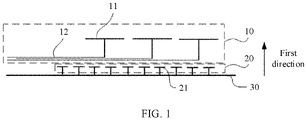
- FIG. 1 shows an antenna system according to an embodiment of this application.
- the antenna system includes a first antenna array 20 and a second antenna array 10.
- the first antenna array 20 and the second antenna array 10 are antennas operating on different operating frequency bands.
- the first antenna array 20 is 5G antennas
- the second antenna array 10 is 2G, 3G, or 4G antennas.
- the first antenna array 20 is 2G, 3G, or 4G antennas
- the second antenna array 10 is 5G antennas.
- the first antenna array 20 includes a plurality of first antennas 21 arranged in arrays. Only one column of first antennas are shown in FIG. 1 . However, it should be understood that a quantity of columns of first antennas 21 is not limited in this embodiment of this application. A plurality of columns of first antennas 21 may be selectively disposed as required, for example, two columns, three columns, or four columns of first antennas 21. When the first antenna array 20 operates, the first antenna array 20 is fed through a first feeding network (not shown in the figure).
- the second antenna array 10 includes a plurality of second antennas 11 arranged in arrays. Only one column of second antennas 11 are shown in FIG. 1 . However, a quantity of second antennas 11 is not specifically limited in this embodiment of this application. A plurality of columns of second antennas 11 may be disposed as required, for example, two columns, three columns, or four columns of second antennas 11. When the second antenna array 10 operates, the second antenna array is fed by a second feeding network 12. The second feeding network 12 is connected to a plurality of second antennas.
- the antenna system further includes a first reflection panel 30.
- the first antenna array 20 and the second antenna array 10 are stacked on the first reflection panel 30 along a first direction.
- the direction indicated by the arrow is the first direction
- the first direction is a direction perpendicular to a reflection surface of the first reflection panel 30.
- the first antennas 21 in the first antenna array 20 are fixedly disposed on the reflection surface of the first reflection panel 30, and the first feeding network is disposed on a side of the first reflection panel 30 that is away from the reflection surface.
- the second antennas 11 in the second antenna array 10 and the second feeding network 12 are disposed at positions away from the first reflection panel 30.
- the second feeding network 12 is disposed between the second antenna array 10 and the first antenna array 20.
- the first antenna array 20 and the first reflection panel 30 are disposed as a whole, and therefore, may be used as one module.
- the second antenna array 10, the first antenna array 20, and the first reflection panel 30 are disposed at intervals.
- an antenna array is disposed on an existing base station.
- a reflection panel of the existing antenna array is removed, and antennas in the existing antenna array are fastened by using a reinforcing structure (such as a radome or a support frame).
- a module including the added antenna array and a reflection panel is added to a side of the antenna array that is opposite to the first direction, to form the structure shown in FIG. 1 .
- the first antenna array 20 is the existing antenna array
- the second antenna array 10 is the added antenna array.
- an added antenna array is directly disposed in front of (a side indicated by the first direction) an existing antenna array, to form the structure shown in FIG. 1 .
- the existing antenna array may be the first antenna array 20 in FIG. 1
- the added antenna array may be the second antenna array 10.
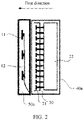
- FIG. 2 shows another specific implementation of an antenna system.
- the antenna system shown in FIG. 2 further includes a first radome 40a and a second radome 50a.
- the first radome 40a and the second radome 50a are arranged in a first direction.
- the second antennas 11 in the second antenna array and the second feeding network 12 are both disposed in the second radome 50a.
- FIG. 2 further shows a first phase shifter 22 of the first antenna array.
- the first phase shifter 22 is disposed in the first radome 40a, and the first phase shifter 22 is connected to a plurality of first antennas 21 through a first feeding network and transmits a signal to the first antennas 21.
- the first antenna array and the first reflection panel 30 form one module by using the first radome 40a.
- the first radome 40a may be directly disposed on a side of the second radome 50a that is opposite to the first direction.
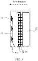
- FIG. 3 is a modification of the antenna system shown in FIG. 2 .
- a first antenna array and a second antenna array are the same as the first antenna array and the second antenna array in FIG. 2 .
- a difference is that only one first radome 40b is disposed in FIG. 3 ; and the second antenna array, a second feeding network 12, the first antenna array, and a first reflection panel 30 are sequentially arranged along a first direction and are disposed in a same radome (the first radome 40b).
- the examples of the antenna systems shown in FIG. 2 and FIG. 3 may be selectively disposed based on actual conditions. Different antenna arrays may be disposed in different radomes or a same radome. This is not specifically limited in this embodiment of this application.
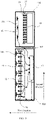
- FIG. 4 shows an example of a specific implementation in which an antenna system includes three antenna arrays.
- the antenna system shown in FIG. 4 includes a first antenna array, a second antenna array, and a third antenna array.
- first antennas 21 in the first antenna array are disposed on a first reflection panel 30 and are connected to a first phase shifter 22 through a first feeding network.
- the first antenna array, the first reflection panel 30, and the first phase shifter 22 are disposed in a first radome 40c.
- a plurality of second antennas 11 in the second antenna array are divided into two parts, which are a first part of second antennas 11a and a second part of second antennas 11b.
- the first part of second antennas 11a include a plurality of second antennas 11a
- the second part of second antennas 11b include a plurality of second antennas 11b.
- the first part of second antennas 11a and a second feeding network 12 correspondingly connected to the first part of second antennas 11a are disposed in a second radome 50c.
- the third antenna array includes a plurality of third antennas 61, and the third antenna array is fed by a third feeding network.
- the second part of second antennas 11b and the third antenna array are disposed on a second reflection panel 70; and the second part of second antennas 11b, the third antenna array, and the second reflection panel 70 are arranged in a first direction.
- the second part of second antennas 11b, the third antenna array, and the second reflection panel 70 are disposed in a third radome 90.
- a second phase shifter 13 and a third phase shifter 62 are further shown.
- the second phase shifter 13 and the third phase shifter 62 are arranged in the third radome 90 along the first direction.
- the second phase shifter 13 is connected to the second phase shifter 13 through the second feeding network corresponding to the second part of second antennas 11b.
- the second feeding network 12 corresponding to the first part of second antennas 11a is connected to the second phase shifter 13 through a jumper 100 between the second radome 50c and the third radome 90.
- the third antenna array is connected to the third phase shifter 62 through a third feeding network.
- the first radome 40c and the second radome 50c are arranged along a first direction; and the first radome 40c, the second radome 50c, and the third radome 90 are arranged along a second direction. As shown in the directions indicated by the arrows in FIG. 4 , the second direction is a direction perpendicular to the first direction. In the antenna system shown in FIG.
- the first reflection panel 30 and the second reflection panel 70 are also arranged along the second direction, so that the second reflection panel 70 and the first antenna array are staggered in space, in other words, the second reflection panel 70 is in an area in which the plurality of first antennas 21 are not overlapped, to prevent the second reflection panel 70 from blocking signal radiation of the first antennas 21, and reduce impact from the second reflection panel 70 on the first antennas 21.
- An arrangement manner for the radome provided in the embodiments of this application is not limited to the manner shown in FIG. 4 .
- the radome shown in FIG. 3 may further be applied to FIG. 4 to form the antenna system shown in FIG. 5 .
- the first radome 40c and the second radome 50c in FIG. 4 may be combined into a first radome 40d, and another radome is a second radome 50d.
- the first radome 40d and the second radome 50d are arranged along the second direction.
- the first part of second antennas 11a, the first antenna array, and the first reflection panel 30 are disposed in the first radome.
- the second part of second antennas 11b, the second reflection panel 70, and the second phase shifter 13 of the second antenna array are disposed in the second radome.
- FIG. 6 shows an example of another specific implementation in which an antenna system includes three antenna arrays.
- the antenna system shown in FIG. 6 includes a first antenna array, a second antenna array, and a third antenna array. Structures of the three antenna arrays are the same as the structures shown in FIG. 4 . Details are not described herein again.
- the antenna system shown in FIG. 6 includes two radomes, which are a first radome 40e and a second radome 50e.
- the second radome 50e is an L-shaped cover, the upper right corner of the second radome 50e has a notch (an arrangement direction of the antenna system in FIG.
- the first radome 40e is disposed at the notch position of the second radome 50e. Still refer to FIG. 6 .
- a plurality of first antennas 21, the first reflection panel 30, and the first phase shifter 22 are arranged in the first radome 40e along a first direction.
- the second radome 50e is an L-shaped structure.
- the first radome 40e is located at the notch position of the second radome 50e.
- the first part of second antennas 11a are located in the second radome 50e and are stacked with the first antenna 21 and the first reflection panel 30 along the first direction.
- the second part of second antennas 11b, the third antenna array, the second reflection panel 70, the third phase shifter 62, and the second phase shifter 13 are stacked in the second radome 50e along the first direction.
- FIG. 7 shows another structure of an antenna system.
- a fourth antenna array is added to the antenna system shown in FIG. 7 .
- a first antenna array, a second antenna array, a third antenna array, and the fourth antenna array are antenna arrays operating on different frequency bands.
- the operating frequency band of the first antenna array is 5G
- the operating frequency band of the second antenna array is 4G
- the operating frequency band of the third antenna array is 3G
- the operating frequency band of the fourth antenna array is 2G. Still refer to FIG. 7 .
- the first antenna array, the second antenna array, and the third antenna array are disposed in a manner the same as that shown in FIG. 6 . Details are not described herein again.
- the fourth antenna array, the second antenna array, and the third antenna array are stacked on a second reflection panel 70.
- the fourth antenna array includes a plurality of fourth antennas 81.
- a fourth phase shifter 82 feeds the fourth antenna array through a fourth feeding network.
- the fourth antenna array and the third antenna array are located on a same side of the second reflection panel 70, and the fourth antenna array is fixedly disposed on the second reflection panel 70.
- the fourth phase shifter 82 and the fourth antennas 81 are separately arranged on two sides of the second reflection panel 70.
- the antenna arrays included in the antenna systems shown in FIG. 4 to FIG. 7 are merely examples.
- a quantity of antenna arrays and a specific combination manner are not limited in the embodiments of this application.
- the antenna systems provided in the embodiments of this application may use a manner shown in FIG. 6 in which the second antenna array and the third antenna array are disposed in one radome and the first antenna array is disposed in another radome, may use a manner in which the second antenna array is independently disposed in one radome and the first antenna array and the third antenna array are disposed in one radome, may use a manner in which the first antenna array and the second antenna array are disposed in one radome and the third antenna array is independently disposed in one radome, and so on.
- the first antenna array, the second antenna array, and the third antenna array may be randomly arranged as required.
- Corresponding radomes may be accordingly assembled based on the arrangement manner for the first antenna array, the second antenna array, and the third antenna array.
- An embodiment of this application further provides a base station.
- the base station includes any one of the foregoing antenna systems and a digital phase shifter connected to the antenna system.
- a digital phase shifter connected to the antenna system.
- different modules may be added to the antenna systems as required to improve communication performance of the existing base station, thereby reducing costs of refitting the base station.
Landscapes
- Engineering & Computer Science (AREA)
- Computer Networks & Wireless Communication (AREA)
- Physics & Mathematics (AREA)
- Electromagnetism (AREA)
- Signal Processing (AREA)
- Variable-Direction Aerials And Aerial Arrays (AREA)
Applications Claiming Priority (1)
| Application Number | Priority Date | Filing Date | Title |
|---|---|---|---|
| PCT/CN2019/122283 WO2021103032A1 (zh) | 2019-11-30 | 2019-11-30 | 一种天线系统及基站 |
Related Child Applications (1)
| Application Number | Title | Priority Date | Filing Date |
|---|---|---|---|
| EP25223641.9 Division-Into | 2025-12-16 |
Publications (4)
| Publication Number | Publication Date |
|---|---|
| EP4047749A1 true EP4047749A1 (de) | 2022-08-24 |
| EP4047749A4 EP4047749A4 (de) | 2022-11-02 |
| EP4047749C0 EP4047749C0 (de) | 2026-02-25 |
| EP4047749B1 EP4047749B1 (de) | 2026-02-25 |
Family
ID=76130037
Family Applications (1)
| Application Number | Title | Priority Date | Filing Date |
|---|---|---|---|
| EP19954138.4A Active EP4047749B1 (de) | 2019-11-30 | 2019-11-30 | Antennensystem und basisstation |
Country Status (4)
| Country | Link |
|---|---|
| US (1) | US20220285858A1 (de) |
| EP (1) | EP4047749B1 (de) |
| CN (3) | CN120184591A (de) |
| WO (1) | WO2021103032A1 (de) |
Families Citing this family (14)
| Publication number | Priority date | Publication date | Assignee | Title |
|---|---|---|---|---|
| US11611143B2 (en) | 2020-03-24 | 2023-03-21 | Commscope Technologies Llc | Base station antenna with high performance active antenna system (AAS) integrated therein |
| CN113950775B (zh) | 2020-03-24 | 2023-01-24 | 康普技术有限责任公司 | 具有有源天线模块的基站天线以及相关装置和方法 |
| US12218425B2 (en) | 2020-04-28 | 2025-02-04 | Outdoor Wireless Networks LLC | Base station antennas having reflector assemblies including a nonmetallic substrate having a metallic layer thereon |
| WO2022182869A1 (en) * | 2021-02-24 | 2022-09-01 | Bluehalo Llc | System and method for a digitally beamformed phased array feed |
| CN215418610U (zh) | 2021-08-31 | 2022-01-04 | 康普技术有限责任公司 | 频率选择反射板和基站天线 |
| CN115882231A (zh) * | 2021-09-29 | 2023-03-31 | 康普技术有限责任公司 | 基站天线装置、基站天线和用于基站天线的天线组件 |
| CN116264346A (zh) * | 2021-12-14 | 2023-06-16 | 华为技术有限公司 | 一种天线系统及基站天馈系统 |
| CN116266664B (zh) * | 2021-12-16 | 2026-02-06 | 华为技术有限公司 | 一种天线系统和通信设备 |
| SE545791C2 (en) * | 2022-05-18 | 2024-02-06 | Saab Ab | An antenna arrangement |
| CN117199772A (zh) | 2022-06-01 | 2023-12-08 | 康普技术有限责任公司 | 基站天线 |
| US12469960B2 (en) | 2022-07-08 | 2025-11-11 | Outdoor Wireless Networks LLC | Base station antennas |
| CN117525819A (zh) * | 2022-07-30 | 2024-02-06 | 华为技术有限公司 | 一种天线系统及基站 |
| CN118198721A (zh) * | 2022-12-14 | 2024-06-14 | 上海华为技术有限公司 | 天线、天线组件和基站 |
| CN116454598A (zh) * | 2023-02-07 | 2023-07-18 | 普罗斯通信技术(苏州)有限公司 | 一体化基站天线及天线基站 |
Family Cites Families (15)
| Publication number | Priority date | Publication date | Assignee | Title |
|---|---|---|---|---|
| CN101465473B (zh) * | 2007-12-20 | 2013-04-10 | 京信通信系统(中国)有限公司 | 多系统共体天线 |
| CN101695926B (zh) * | 2009-10-15 | 2012-05-23 | 深圳市旺龙智能科技有限公司 | 轨道交通智能安全预警系统 |
| KR101125180B1 (ko) * | 2009-11-17 | 2012-03-19 | 주식회사 케이엠더블유 | 서로 다른 평면에 배치되는 방사소자들의 설치 방법 및 이를 이용한 안테나 |
| CN101714701B (zh) * | 2009-12-21 | 2013-06-19 | 京信通信系统(中国)有限公司 | 双频双极化阵列天线 |
| CN102395226B (zh) * | 2011-11-02 | 2014-10-08 | 华为技术有限公司 | 一种有源天线系统、基站和通信系统 |
| WO2012103821A2 (zh) * | 2012-03-09 | 2012-08-09 | 华为技术有限公司 | 天线系统、基站和通信系统 |
| JP6848863B2 (ja) * | 2015-07-08 | 2021-03-24 | 日本電気株式会社 | 無線通信装置 |
| CN205723963U (zh) * | 2016-03-31 | 2016-11-23 | 中国移动通信有限公司研究院 | 一种宏站天线 |
| WO2018077408A1 (en) * | 2016-10-27 | 2018-05-03 | Huawei Technologies Co., Ltd. | Compact dual-band mimo antenna |
| EP3996205B1 (de) * | 2017-01-24 | 2025-06-25 | Outdoor Wireless Networks LLC | Basisstationsantennen mit zusätzlichen arrays |
| KR101750336B1 (ko) * | 2017-03-31 | 2017-06-23 | 주식회사 감마누 | 다중대역 기지국 안테나 |
| CN108666742B (zh) * | 2017-03-31 | 2021-08-03 | 华为技术有限公司 | 多频天线及通信设备 |
| CN111066200B (zh) * | 2017-10-30 | 2021-11-19 | 华为技术有限公司 | 天线、天线组件及基站 |
| EP3573179B1 (de) * | 2018-05-24 | 2023-09-20 | Nokia Shanghai Bell Co., Ltd. | Antennensystem |
| SE1930346A1 (en) * | 2019-10-25 | 2020-10-20 | Gapwaves Ab | ULTRA WIDEBAND CIRCULAR POLARIZED RADIATION ELEMENT WITH INTEGRATED FEEDING |
-
2019
- 2019-11-30 CN CN202510142413.1A patent/CN120184591A/zh active Pending
- 2019-11-30 EP EP19954138.4A patent/EP4047749B1/de active Active
- 2019-11-30 CN CN202510148685.2A patent/CN120184592A/zh active Pending
- 2019-11-30 CN CN201980102146.8A patent/CN114730990B/zh active Active
- 2019-11-30 WO PCT/CN2019/122283 patent/WO2021103032A1/zh not_active Ceased
-
2022
- 2022-05-29 US US17/827,727 patent/US20220285858A1/en active Pending
Also Published As
| Publication number | Publication date |
|---|---|
| CN120184592A (zh) | 2025-06-20 |
| EP4047749C0 (de) | 2026-02-25 |
| CN114730990B (zh) | 2025-02-21 |
| US20220285858A1 (en) | 2022-09-08 |
| CN114730990A (zh) | 2022-07-08 |
| EP4047749A4 (de) | 2022-11-02 |
| CN120184591A (zh) | 2025-06-20 |
| WO2021103032A1 (zh) | 2021-06-03 |
| EP4047749B1 (de) | 2026-02-25 |
Similar Documents
| Publication | Publication Date | Title |
|---|---|---|
| US20220285858A1 (en) | Antenna system and base station | |
| US10903550B2 (en) | Base station antennas including supplemental arrays | |
| US6646611B2 (en) | Multiband telecommunication antenna | |
| US9306270B2 (en) | Antenna array and method for operating antenna array | |
| US9438278B2 (en) | Multi-array antenna | |
| EP3503300A1 (de) | Multisystemintegrierte antenne | |
| US11456544B2 (en) | Multiband antenna array with massive multiple input multiple output array | |
| EP3379648B1 (de) | Flachantennengruppe und kommunikationsvorrichtung | |
| EP1900063B1 (de) | Verbesserte repeater-antenne zur verwendung in punkt-zu-punkt-anwendungen | |
| EP3930099B1 (de) | Zweidimensionale antenne und netzwerkvorrichtung | |
| EP4451461A1 (de) | Antennensystem und basisstationsantennenzuführsystem | |
| US20200106182A1 (en) | Antenna array including suppressor | |
| US20190363451A1 (en) | Antenna system | |
| EP3057179B1 (de) | Antennensystem und basisstation | |
| CN109167186A (zh) | 一种基于5g通信的共口径双频段相控阵天线系统 | |
| CN114946086B (zh) | 利用四极化天线模块阵列实现波束的空间-极化分离的fdd方式的天线装置 | |
| EP3883058A1 (de) | Antennenvorrichtung | |
| WO2023044283A1 (en) | Base station antenna systems having modular base station antennas with interconnected arrays | |
| EP4089835A1 (de) | Mehrstrahlenantenne | |
| JP3239043B2 (ja) | 移動通信用基地局 | |
| US12412995B2 (en) | Fence structure and base station antenna comprising the same | |
| KR102411588B1 (ko) | 위상배열 안테나 | |
| EP3955386A1 (de) | Strahlungseinheit, antennenarray und netzwerkvorrichtung | |
| KR20020014780A (ko) | 이동통신시스템의 안테나 장치 | |
| CN121602044A (zh) | 一种天线、通信设备和通信系统 |
Legal Events
| Date | Code | Title | Description |
|---|---|---|---|
| STAA | Information on the status of an ep patent application or granted ep patent |
Free format text: STATUS: THE INTERNATIONAL PUBLICATION HAS BEEN MADE |
|
| PUAI | Public reference made under article 153(3) epc to a published international application that has entered the european phase |
Free format text: ORIGINAL CODE: 0009012 |
|
| STAA | Information on the status of an ep patent application or granted ep patent |
Free format text: STATUS: REQUEST FOR EXAMINATION WAS MADE |
|
| 17P | Request for examination filed |
Effective date: 20220516 |
|
| AK | Designated contracting states |
Kind code of ref document: A1 Designated state(s): AL AT BE BG CH CY CZ DE DK EE ES FI FR GB GR HR HU IE IS IT LI LT LU LV MC MK MT NL NO PL PT RO RS SE SI SK SM TR |
|
| A4 | Supplementary search report drawn up and despatched |
Effective date: 20221004 |
|
| RIC1 | Information provided on ipc code assigned before grant |
Ipc: H01Q 21/28 20060101ALI20220927BHEP Ipc: H01Q 1/24 20060101ALI20220927BHEP Ipc: H01Q 21/00 20060101ALI20220927BHEP Ipc: H01Q 5/00 20150101AFI20220927BHEP |
|
| DAV | Request for validation of the european patent (deleted) | ||
| DAX | Request for extension of the european patent (deleted) | ||
| STAA | Information on the status of an ep patent application or granted ep patent |
Free format text: STATUS: EXAMINATION IS IN PROGRESS |
|
| 17Q | First examination report despatched |
Effective date: 20250210 |
|
| REG | Reference to a national code |
Ref country code: DE Free format text: PREVIOUS MAIN CLASS: H01Q0005000000 Ref country code: DE Ref legal event code: R079 Ref document number: 602019081955 Country of ref document: DE Free format text: PREVIOUS MAIN CLASS: H01Q0005000000 Ipc: H01Q0001120000 |
|
| GRAP | Despatch of communication of intention to grant a patent |
Free format text: ORIGINAL CODE: EPIDOSNIGR1 |
|
| STAA | Information on the status of an ep patent application or granted ep patent |
Free format text: STATUS: GRANT OF PATENT IS INTENDED |
|
| RIC1 | Information provided on ipc code assigned before grant |
Ipc: H01Q 1/12 20060101AFI20250901BHEP Ipc: H01Q 5/42 20150101ALI20250901BHEP Ipc: H01Q 1/24 20060101ALI20250901BHEP Ipc: H01Q 21/28 20060101ALI20250901BHEP |
|
| INTG | Intention to grant announced |
Effective date: 20250919 |
|
| GRAS | Grant fee paid |
Free format text: ORIGINAL CODE: EPIDOSNIGR3 |
|
| GRAA | (expected) grant |
Free format text: ORIGINAL CODE: 0009210 |
|
| STAA | Information on the status of an ep patent application or granted ep patent |
Free format text: STATUS: THE PATENT HAS BEEN GRANTED |
|
| AK | Designated contracting states |
Kind code of ref document: B1 Designated state(s): AL AT BE BG CH CY CZ DE DK EE ES FI FR GB GR HR HU IE IS IT LI LT LU LV MC MK MT NL NO PL PT RO RS SE SI SK SM TR |
|
| REG | Reference to a national code |
Ref country code: CH Ref legal event code: F10 Free format text: ST27 STATUS EVENT CODE: U-0-0-F10-F00 (AS PROVIDED BY THE NATIONAL OFFICE) Effective date: 20260225 Ref country code: GB Ref legal event code: FG4D |
|
| REG | Reference to a national code |
Ref country code: IE Ref legal event code: FG4D |