EP4047719A1 - Battery module and method for manufacturing same - Google Patents
Battery module and method for manufacturing same Download PDFInfo
- Publication number
- EP4047719A1 EP4047719A1 EP21822818.7A EP21822818A EP4047719A1 EP 4047719 A1 EP4047719 A1 EP 4047719A1 EP 21822818 A EP21822818 A EP 21822818A EP 4047719 A1 EP4047719 A1 EP 4047719A1
- Authority
- EP
- European Patent Office
- Prior art keywords
- battery cell
- accommodation groove
- battery
- heat dissipation
- heat transfer
- Prior art date
- Legal status (The legal status is an assumption and is not a legal conclusion. Google has not performed a legal analysis and makes no representation as to the accuracy of the status listed.)
- Granted
Links
Images


Classifications
-
- H—ELECTRICITY
- H01—ELECTRIC ELEMENTS
- H01M—PROCESSES OR MEANS, e.g. BATTERIES, FOR THE DIRECT CONVERSION OF CHEMICAL ENERGY INTO ELECTRICAL ENERGY
- H01M10/00—Secondary cells; Manufacture thereof
- H01M10/60—Heating or cooling; Temperature control
- H01M10/65—Means for temperature control structurally associated with the cells
- H01M10/655—Solid structures for heat exchange or heat conduction
- H01M10/6554—Rods or plates
-
- H—ELECTRICITY
- H01—ELECTRIC ELEMENTS
- H01M—PROCESSES OR MEANS, e.g. BATTERIES, FOR THE DIRECT CONVERSION OF CHEMICAL ENERGY INTO ELECTRICAL ENERGY
- H01M10/00—Secondary cells; Manufacture thereof
- H01M10/60—Heating or cooling; Temperature control
- H01M10/65—Means for temperature control structurally associated with the cells
- H01M10/655—Solid structures for heat exchange or heat conduction
-
- H—ELECTRICITY
- H01—ELECTRIC ELEMENTS
- H01M—PROCESSES OR MEANS, e.g. BATTERIES, FOR THE DIRECT CONVERSION OF CHEMICAL ENERGY INTO ELECTRICAL ENERGY
- H01M10/00—Secondary cells; Manufacture thereof
- H01M10/60—Heating or cooling; Temperature control
- H01M10/61—Types of temperature control
- H01M10/617—Types of temperature control for achieving uniformity or desired distribution of temperature
-
- H—ELECTRICITY
- H01—ELECTRIC ELEMENTS
- H01M—PROCESSES OR MEANS, e.g. BATTERIES, FOR THE DIRECT CONVERSION OF CHEMICAL ENERGY INTO ELECTRICAL ENERGY
- H01M10/00—Secondary cells; Manufacture thereof
- H01M10/04—Construction or manufacture in general
-
- H—ELECTRICITY
- H01—ELECTRIC ELEMENTS
- H01M—PROCESSES OR MEANS, e.g. BATTERIES, FOR THE DIRECT CONVERSION OF CHEMICAL ENERGY INTO ELECTRICAL ENERGY
- H01M10/00—Secondary cells; Manufacture thereof
- H01M10/60—Heating or cooling; Temperature control
- H01M10/61—Types of temperature control
- H01M10/613—Cooling or keeping cold
-
- H—ELECTRICITY
- H01—ELECTRIC ELEMENTS
- H01M—PROCESSES OR MEANS, e.g. BATTERIES, FOR THE DIRECT CONVERSION OF CHEMICAL ENERGY INTO ELECTRICAL ENERGY
- H01M10/00—Secondary cells; Manufacture thereof
- H01M10/60—Heating or cooling; Temperature control
- H01M10/64—Heating or cooling; Temperature control characterised by the shape of the cells
- H01M10/647—Prismatic or flat cells, e.g. pouch cells
-
- H—ELECTRICITY
- H01—ELECTRIC ELEMENTS
- H01M—PROCESSES OR MEANS, e.g. BATTERIES, FOR THE DIRECT CONVERSION OF CHEMICAL ENERGY INTO ELECTRICAL ENERGY
- H01M10/00—Secondary cells; Manufacture thereof
- H01M10/60—Heating or cooling; Temperature control
- H01M10/65—Means for temperature control structurally associated with the cells
- H01M10/651—Means for temperature control structurally associated with the cells characterised by parameters specified by a numeric value or mathematical formula, e.g. ratios, sizes or concentrations
- H01M10/652—Means for temperature control structurally associated with the cells characterised by parameters specified by a numeric value or mathematical formula, e.g. ratios, sizes or concentrations characterised by gradients
-
- H—ELECTRICITY
- H01—ELECTRIC ELEMENTS
- H01M—PROCESSES OR MEANS, e.g. BATTERIES, FOR THE DIRECT CONVERSION OF CHEMICAL ENERGY INTO ELECTRICAL ENERGY
- H01M10/00—Secondary cells; Manufacture thereof
- H01M10/60—Heating or cooling; Temperature control
- H01M10/65—Means for temperature control structurally associated with the cells
- H01M10/653—Means for temperature control structurally associated with the cells characterised by electrically insulating or thermally conductive materials
-
- H—ELECTRICITY
- H01—ELECTRIC ELEMENTS
- H01M—PROCESSES OR MEANS, e.g. BATTERIES, FOR THE DIRECT CONVERSION OF CHEMICAL ENERGY INTO ELECTRICAL ENERGY
- H01M10/00—Secondary cells; Manufacture thereof
- H01M10/60—Heating or cooling; Temperature control
- H01M10/65—Means for temperature control structurally associated with the cells
- H01M10/655—Solid structures for heat exchange or heat conduction
- H01M10/6551—Surfaces specially adapted for heat dissipation or radiation, e.g. fins or coatings
-
- H—ELECTRICITY
- H01—ELECTRIC ELEMENTS
- H01M—PROCESSES OR MEANS, e.g. BATTERIES, FOR THE DIRECT CONVERSION OF CHEMICAL ENERGY INTO ELECTRICAL ENERGY
- H01M10/00—Secondary cells; Manufacture thereof
- H01M10/60—Heating or cooling; Temperature control
- H01M10/65—Means for temperature control structurally associated with the cells
- H01M10/656—Means for temperature control structurally associated with the cells characterised by the type of heat-exchange fluid
-
- H—ELECTRICITY
- H01—ELECTRIC ELEMENTS
- H01M—PROCESSES OR MEANS, e.g. BATTERIES, FOR THE DIRECT CONVERSION OF CHEMICAL ENERGY INTO ELECTRICAL ENERGY
- H01M50/00—Constructional details or processes of manufacture of the non-active parts of electrochemical cells other than fuel cells, e.g. hybrid cells
- H01M50/20—Mountings; Secondary casings or frames; Racks, modules or packs; Suspension devices; Shock absorbers; Transport or carrying devices; Holders
- H01M50/204—Racks, modules or packs for multiple batteries or multiple cells
- H01M50/207—Racks, modules or packs for multiple batteries or multiple cells characterised by their shape
- H01M50/211—Racks, modules or packs for multiple batteries or multiple cells characterised by their shape adapted for pouch cells
-
- H—ELECTRICITY
- H01—ELECTRIC ELEMENTS
- H01M—PROCESSES OR MEANS, e.g. BATTERIES, FOR THE DIRECT CONVERSION OF CHEMICAL ENERGY INTO ELECTRICAL ENERGY
- H01M10/00—Secondary cells; Manufacture thereof
- H01M10/60—Heating or cooling; Temperature control
- H01M10/65—Means for temperature control structurally associated with the cells
- H01M10/655—Solid structures for heat exchange or heat conduction
- H01M10/6553—Terminals or leads
-
- Y—GENERAL TAGGING OF NEW TECHNOLOGICAL DEVELOPMENTS; GENERAL TAGGING OF CROSS-SECTIONAL TECHNOLOGIES SPANNING OVER SEVERAL SECTIONS OF THE IPC; TECHNICAL SUBJECTS COVERED BY FORMER USPC CROSS-REFERENCE ART COLLECTIONS [XRACs] AND DIGESTS
- Y02—TECHNOLOGIES OR APPLICATIONS FOR MITIGATION OR ADAPTATION AGAINST CLIMATE CHANGE
- Y02E—REDUCTION OF GREENHOUSE GAS [GHG] EMISSIONS, RELATED TO ENERGY GENERATION, TRANSMISSION OR DISTRIBUTION
- Y02E60/00—Enabling technologies; Technologies with a potential or indirect contribution to GHG emissions mitigation
- Y02E60/10—Energy storage using batteries
Definitions
- the present invention relates to a battery module and a method for manufacturing the same, and more particularly, to a battery module, in which a battery cell increases in heat dissipation performance and decreases in temperature deviation, and a method for manufacturing the same.
- secondary batteries refer to chargeable and dischargeable, unlike primary batteries that are not chargeable.
- the secondary batteries are being widely used for mobile phones, notebook computers, and camcorders, power storage device, electric vehicles, and the like.
- Such a secondary battery is classified into a can type secondary battery in which an electrode assembly is built in a metal can and a pouch type secondary battery in which an electrode assembly is built in a pouch.
- the pouch type secondary battery comprises an electrode assembly in which an electrode and a separator are alternately stacked, and a pouch accommodating the electrode assembly.
- the battery pack comprises a battery module comprising a plurality of battery cells, and the plurality of battery cells are connected to each other in series or parallel to increase in capacity and output.
- the above-described battery module generates more heat as the capacity and output increase, and thus, if the heat generated from the battery module is not smoothly released to the outside, deterioration, ignition, and explosion of the battery module may occur.
- an object of the present invention is to provide a battery module that is capable of reducing a temperature deviation of the entire battery module and a method for manufacturing the same.
- the cover plate may comprise a first accommodation groove provided in a center of one surface thereof and having a structure connected in the longitudinal direction of the battery cell and second accommodation grooves provided in both sides of the first accommodation groove in a thickness direction of the battery cell and having a structure, in which an interval therebetween is gradually narrowed from the center toward both the ends of the battery cell, and the first heat transfer material is provided in the first accommodation groove, and the second heat transfer material is provided in the second accommodation groove.
- the first and second heat transfer materials may be integrally connected to each other.
- An insulating member having an insulating property may be provided on one surface of the cover plate except for the first and second accommodation grooves.
- a pair of heat dissipation pads which reduces a temperature deviation between a center and both the ends of the battery cell by releasing the heat generated at both the ends of the battery cell may be provided on both ends of an inner surface of the battery case, respectively.
- a finishing pad that finishes a space between the pair of heat dissipation pads may be provided on the inner surface of the battery case between the pair of heat dissipation pads.
- the first accommodation groove may be provided to have a depth that gradually increases from the center toward both the ends of the battery cell, and the first heat transfer material provided in the first accommodation groove may be provided to have a thickness that gradually increases from the center toward both the ends of the battery cell.
- a depth may gradually increase from the second accommodation groove disposed at the center of the battery cell toward the second accommodation groove disposed at each of both the ends of the battery cell, and each of the second heat transfer materials provided in the second accommodation groove may be provided to have a thickness that gradually increases from the center toward both the ends of the battery cell.
- a method for manufacturing a battery module comprises: a disposition step of disposing a plurality of battery cells to overlap each other in a thickness direction; an accommodation step of accommodating the plurality of overlapping battery cells in a battery case of which a lower portion is opened; a preparation step of preparing a heat dissipation member comprising a cover plate and a heat dissipation body provided on one surface of the cover plate, on which the battery cells are supported; and a coupling step of coupling the cover plate of the heat dissipation member to a lower portion of the battery case and supporting the heat dissipation body on the battery cells, wherein the preparation step comprises a preparation process of preparing the cover plate, a forming process of pressing one surface of the cover plate to form a first accommodation groove and a second accommodation groove, and an injection process of injecting a heat transfer solution into the first accommodation groove and the second accommodation groove to manufacture the heat dissipation body, wherein the heat dissipation body comprises a first heat transfer material formed
- the first accommodation groove and the second accommodation groove may be formed to be connected to each other, and in the injection process, since the first accommodation groove and the second accommodation groove are connected to each other, the heat dissipation body, in which the first heat transfer material and the second heat transfer material are integrally connected to each other, may be manufactured.
- the method may further comprise an attachment process of attaching an insulating member having an insulating property to one surface of the cover plate except for the first accommodation groove and the second accommodation groove between the forming process and the injection process.
- the accommodation step may further comprise a process of respectively attaching heat dissipation pads, each of which has heat dissipation performance, to both ends of an inner surface of the battery case, which correspond to both the ends of the battery cell.
- the accommodation step may further comprise a process of attaching a finishing pad to the inner surface of the battery case between the heat dissipation pads.
- the battery module according to the present invention may comprise the plurality of battery cells, the battery case, and the heat dissipation member comprising the cover plate and the heat dissipation body.
- the heat dissipation body may comprise the first heat transfer material and the second heat transfer materials, which are arranged in a plurality of rows. Due to the above-described characteristics, the heat generated in the battery cell may be smoothly released through the first and second heat transfer materials, and thus, the increase in temperature of the battery module may be significantly suppressed.
- the first heat transfer materials may be aligned so that an interval therebetween is gradually narrowed from the center toward both the ends of the battery cell. Due to the above-described characteristic, the heat dissipation performance may be gradually improved from the center toward both the ends of the battery cell, and thus, the temperature deviation from the center to both the ends of the battery cell may be reduced to improve the performance of the battery module.
- the cover plate may comprise the first accommodation groove and the second accommodation groove, which are formed in a concave shape.
- the first heat transfer material may be provided in the first accommodation groove
- the second heat transfer material may be provided in the second accommodation groove. Due to the above-described characteristics, the first and second heat transfer materials may be effectively provided.
- the insulating member having the insulating property may be provided on one surface of the cover plate except for the first and second accommodation grooves. Due to the above-described characteristic, the occurrence of the short circuit due to the contact between the battery cell and the cover plate may be previously prevented to improve the safety.
- the first accommodation groove may have the depth that gradually increases from the center to both the ends of the battery cell. Due to the above-described characteristic, the first heat transfer material provided in the first accommodation groove may have the height that gradually increases from the center to both the ends of the battery cell, and thus, the heat dissipation performance at both the ends of the battery cell when compared to the center of the battery cell may be improved, and as a result, the temperature deviation of the entire battery cell may be reduced.
- the second accommodation groove may have the depth that gradually increases from the center to both the ends of the battery cell. Due to the above-described characteristic, the second heat transfer material provided in the second accommodation groove may have the height that gradually increases from the center to both the ends of the battery cell, and thus, the heat dissipation performance at both the ends of the battery cell when compared to the center of the battery cell may be improved, and as a result, the temperature deviation of the entire battery cell may be reduced.
- the pair of heat dissipation pads may be provided at both the ends of the inner surface of the battery case. Due to the above-described characteristic, the heat dissipation performance at both the ends of the upper portion of the battery cell may be significantly improved, and thus, the temperature deviation of the entire battery cell may be significantly reduced.
- a heat dissipation structure is improved to improve heat dissipation performance of the battery cell and reduce a temperature deviation of the entire battery cell.
- the battery module 100 comprises a plurality of battery cells 110 disposed to overlap each other in a thickness direction thereof, a battery case 120 accommodating the battery cells 110 and having a structure of which a lower portion is opened, and a heat dissipation member 130 coupled to the lower portion of the battery case 120 to release heat generated in the plurality of battery cells 110, which are accommodated in the battery case 120, to the outside.
- the heat dissipation member is coupled to the lower portion of the battery case as one embodiment, but the heat dissipation member may be provided on an upper portion, a side portion, a front portion, or a rear portion of the battery case according to application of a product.
- the battery cell 110 comprises an electrode assembly, an electrode lead connected to the electrode assembly, and a pouch case accommodating the electrode assembly in a state in which a front end of the electrode lead is drawn out.
- the battery cell 110 having the above-described configuration is provided in plurality, which are disposed to overlap each other in the thickness direction, and the plurality of battery cells 110 arranged in the thickness direction have a structure, in which the plurality of battery cells 110 are connected in series or in parallel.
- the battery case 120 is configured to accommodate the plurality of battery cells and has a rectangular box shape in which an opening is formed in a lower portion thereof.
- the plurality of battery cells 110 overlapping each other are accommodated in the battery case 120 through the opening.
- Each of the battery cells 110 is accommodated in the battery case 120 in a state in which the electrode lead faces an end in a longitudinal direction of the battery case 120 and is upright.
- the heat dissipation member 130 comprises a cover plate 131 supporting the battery cell 110 accommodated in the battery case 120 and a heat dissipation body 132 releasing heat generated in the battery cell 110 to the outside.
- the cover plate 131 may be coupled to the lower portion of the battery case 120 to finish the lower portion of the battery case 120 and also supports the lower portion of the battery cell 110 accommodated in the battery case 120 to prevent the battery cell 110 from being drawn out to the outside.
- the cover plate 131 is made of a heat dissipation material that is capable of smoothly releasing the heat of the battery cell, which is transferred from the heat dissipation body.
- the heat dissipation body 132 is provided on one surface of the cover plate 131, on which the battery cell 110 is supported, to absorb the heat generated in the battery cell 110, thereby releasing the heat to the outside. Thus, the heat of the battery cell 110 may be effectively dissipated.
- the heat dissipation body 132 comprises a first heat transfer material 132a provided to be connected to a center of one surface of the cover plate 131 in a longitudinal direction (a left and right direction of the cover plate when viewed in FIG. 4 ) of the battery cell and a second heat transfer material 132b provided at each of both portions (upper and lower portions of the first heat transfer material when viewed in FIG. 4 ) of the first heat transfer material 132a and having a structure arranged in a plurality of rows in the longitudinal direction (the left and right direction of the cover plate when viewed in FIG. 4 ) of the battery cell.
- Each of the first and second heat transfer materials 132a and 132b may be provided as a contact thermal interface material (TIM) and have an adhesive property.
- TIM contact thermal interface material
- at least one of heat dissipation grease, a thermal conductive adhesive, or a phase change material may be used as each of the first and second heat transfer materials 132a and 132b.
- the heat dissipation body 132 having the above-described configuration may be differently applied to a center of the battery cell 110, at which a relatively large amount of heat is generated, and both overlapping portions of the battery cell 110, at which a relatively small amount of heat when compared to that of the center of the battery cell 110 is generated, and thus, the heat dissipation performance of the battery cell 110 may be improved, and also, the temperature deviation between the center and both the portions of the battery cell 110 may be reduced.
- the present invention has the arrangement structure of the second heat transfer materials 132b for reducing the temperature deviation of the battery cell 110 as described above.
- the second heat transfer materials 132b have a structure aligned in a plurality of rows so that an interval therebetween is gradually narrowed from an outer central point (a point at which the battery cell is bisected in the longitudinal direction) toward both ends (both end points of the battery cell in the longitudinal direction).
- more second heat transfer materials 132b are arranged at both the ends of the battery cell, which generates high-temperature heat are arranged to significantly improve the heat dissipation performance
- less second heat transfer materials 132b are arranged at the central portion of the battery cell, which generate low-temperature heat to slightly improve the heat dissipation performance.
- the temperature deviation may be significantly reduced due to a difference in heat dissipation performance between the central portion and both the ends of the battery cell.
- the heat dissipation member 130 having the above configuration may significantly improve the heat dissipation performance of the plurality of battery cells 110 accommodated in the battery case 120, and in particular, may reduce the temperature deviation of the plurality of entire battery cells to improve performance of the battery cells.
- the cover plate 131 comprises a first accommodation groove 131a provided in a center of one surface thereof and having a structure connected in a longitudinal direction of the battery cell 110 and second accommodation grooves 131b respectively provided in both sides of the first accommodation groove 131a in a thickness direction of the battery cell 110 and having a structure, in which an interval therebetween is gradually narrowed from the center toward both ends of the battery cell 110.
- the first heat transfer material 132a is provided in the first accommodation groove 131a
- the second heat transfer material 132b is provided in the second accommodation groove 131b.
- the first accommodation groove 131a and the second accommodation groove 131b have a structure formed in a concave shape on a top surface of the cover plate 131 when viewed in FIG. 3 .
- first heat transfer material 132a and the second heat transfer materials 132b are made of the same material.
- the heat dissipation member 130 having the above-described configuration forms the first accommodation groove 131a and the second accommodation groove 131b in one surface of the cover plate 131 to easily form the first heat transfer material 132a and the second heat transfer materials 132b.
- the first accommodation groove 131a and the second accommodation groove 131b are formed to be connected to each other.
- the first and second heat transfer materials 132a and 132b provided in the first accommodation groove 131a and the second accommodation groove 131b may be integrally connected to each other, and as a result, heat generated in the battery cell 110 may be dispersed throughout the first and second heat transfer materials 132a and 132b to improve the heat dissipation performance.
- An insulating member 133 having an insulating property is provided on one surface of the cover plate 131 except for the first and second accommodation grooves 131a and 131b. That is, the insulating member 133 insulates the battery cell 110 and the cover plate 131 from each other to prevent a short circuit that may occur when the battery cell 110 and the cover plate 131 are in contact with each other.
- the insulating member 133 has an adhesive tape shape and is attached to one surface of the cover plate 131. Therefore, convenience of use may be improved.
- a coating layer is further provided between an end of the insulating member 133 and the cover plate 131 to prevent the heat transfer material from being introduced between the end of the insulating member 133 and the cover plate.
- the coating layer may prevent the end of the insulating member 133 from being separated the cover plate 131.
- the battery module 100 according to the first embodiment of the present invention further comprises a heat dissipation pad 140.
- the heat dissipation pad 140 is configured to reduce a temperature deviation between the upper central portion and both the ends of the battery cell
- both the ends of the battery cell generate heat having a temperature higher than that of the center of the battery cell because the electrode leads are connected, and thus, the heat dissipation pads 140 may be further provided to reduce the temperature deviation between the center of the top surface and both the ends of the battery cell.
- the heat dissipation pads 140 are attached to both sides of an inner surface of the battery case 120, respectively, and both ends of the top surface of the battery cell 110 accommodated in the battery case 120 are supported to release heat through both the ends of the top surface of the battery cell 110.
- the temperature deviation between the center and both the ends of the battery cell may be significantly reduced through the increase in heat dissipation performance at both the ends of the battery cell.
- a finishing pad 150 may be further provided to constantly maintain an interval between the heat dissipation pads 140, which are attached to both sides of the inner surface of the battery case 120, respectively.
- the finishing pad 150 is attached to the inner surface of the battery case 120 between the pair of heat dissipation pads 140 to constantly maintain the interval between the pair of heat dissipation pads 140.
- the finishing pad 150 may finish a space between the pair of heat dissipation pads 140 to prevent the battery cell 110 from being deformed because the battery cell 110 is inserted into the space between the pair of heat dissipation pads 140.
- a method for manufacturing the battery module according to the first embodiment of the present invention comprises a disposition step, an accommodation step, a preparation step, and a coupling step.
- a plurality of battery cells 110 are prepared, the plurality of prepared battery cells 110 are disposed to overlap each other in a thickness direction, and the plurality of battery cells 110, which are disposed to overlap each other, are connected to each other in series or parallel to be in contact with each other.
- the plurality of battery cells 110 overlapping each other are accommodated in the battery case 120 having an opened lower portion.
- each of the battery cells 110 is accommodated in a state in which the electrode lead faces an end in a longitudinal direction of the battery case 120 and is upright.
- the accommodation step further comprises a step of attaching the heat dissipation pad 140 to both ends of an inner surface of the battery case 120, which correspond to both ends of a top surface of the battery cell 110, respectively, and the heat dissipation pad 140 improves heat dissipation performance at both the ends of the top surface of the battery cell 110.
- the accommodation step further comprises a step of attaching a finishing pad 150 to the inner surface of the battery case 120 between the heat dissipation pads 140, and the finishing pad 150 constantly maintains an interval between the pair of heat dissipation pads 140 to finish a space between the pair of heat dissipation pads 140.
- the preparation steps comprises a preparation process of preparing the cover plate 131, a forming process of forming an accommodation groove for providing a heat dissipation body in the cover plate 131, and an injection process of manufacturing a heat dissipation body 132 through the accommodation groove formed in a cover plate 131.
- the cover plate 131 having a size and shape corresponding to an opened lower portion of the battery case 120 is prepared.
- a first accommodation groove 131a and a second accommodation groove 131b are formed in a concave shape by pressing one surface (a top surface of the cover plate when viewed in FIG. 11 ) of the cover plate 131 by using a press, are formed.
- the first accommodation groove 131a is formed to be connected to a center of one surface of the cover plate 131 in a longitudinal direction of the battery cell, and the second accommodation groove 131b is provided in both portions of the first accommodation groove 131a and having a structure aligned in a plurality of rows in the longitudinal direction of the battery cell 110.
- the second accommodation grooves 131b are formed in one surface of the cover plate 131 so that an interval between the second accommodation grooves 131b is gradually narrowed from a center toward both ends of the battery cell 110.
- the second heat transfer materials 132b provided in the second accommodation groove 131b may be manufactured to have a structure in which an interval between the second heat transfer materials 132b is gradually narrowed from the center toward both the ends of the battery cell 110.
- the first accommodation groove 131a and the second accommodation groove 131b are formed to be connected to each other.
- the heat transfer solution may be injected up to other accommodation grooves, and as a result, operation efficiency may be improved.
- the first and second heat transfer materials 132a and 132b manufactured in the first accommodation groove 131a and the second accommodation groove 131b may be manufactured to be integrally connected to each other, thereby improving heat dissipation performance.
- An attachment process of attaching an insulating member having an insulating property to one surface of the cover plate 131 except for the first accommodation groove 131a and the second accommodation groove 131b is performed between the forming process and the injection process.
- the insulating member 133 having adhesive force is attached to one surface of the cover plate 131.
- a coating solution is applied between an end of the insulating member 133 and the cover plate 131 to prepare a coating layer.
- a heat transfer solution 132c is injected into the first accommodation groove 131a and the second accommodation groove 131b to manufacture a heat dissipation body 132 comprising the first heat transfer material 132a and the second heat transfer material 132b. That is, as the heat transfer solution 132c is applied to the first accommodation groove 131a and solidified, the first heat transfer material 132a is prepared, and as the heat transfer solution 132c is applied to the second accommodation groove 131b and solidified, the second heat transfer material 132b is prepared.
- the first accommodation groove 131a and the second accommodation groove 131b are connected to each other, the first heat transfer material 132a and the second heat transfer material 132b may be manufactured to be integrally connected to each other.
- the finished battery module 100 illustrated in FIG. 2 may be manufactured.
- a battery module 100 As shown in FIG. 14 , a battery module 100 according to a second embodiment of the present invention comprise a first accommodation groove 131a provided in a center of one surface thereof and having a structure connected in a longitudinal direction of the battery cell 110 and second accommodation grooves 131b provided in both sides of the first accommodation groove 131a in a thickness direction of the battery cell 110 and having a structure, in which an interval therebetween is gradually narrowed from the center toward both ends of the battery cell 110.
- the first accommodation groove 131a is provided to gradually increase in depth from the center to both the ends of the battery cell 110, and thus, the first heat transfer material 132a provided in the first accommodation groove 131a has a structure in which a height thereof gradually increases from the center to both the ends of the battery cell 110.
- heat dissipation performance may be applied differently from the middle to both the ends of the battery cell 110 disposed at the center, and thus, the battery cell disposed at the center of the battery case may be reduced in temperature deviation.
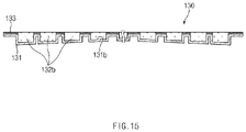
- a battery module 100 As shown in FIG. 15 , a battery module 100 according to a third embodiment of the present invention comprise a first accommodation groove 131a provided in a center of one surface thereof and having a structure connected in a longitudinal direction of the battery cell 110 and second accommodation grooves 131b provided in both sides of the first accommodation groove 131a in a thickness direction of the battery cell 110 and having a structure, in which an interval therebetween is gradually narrowed from the center toward both ends of the battery cell 110.
- the second accommodation groove 131b is provided to gradually increase in depth from the center to both the ends of the battery cell 110, and thus, the second heat transfer material 132b provided in the second accommodation groove 131b has a structure in which a height thereof gradually increases from the center to both the ends of the battery cell 110.
- heat dissipation performance may be more precisely adjusted from the middle to both the ends of the battery cell 110 disposed at each of both the ends of the battery case, and thus, the battery cell disposed at each of both the ends of the battery case may be reduced in temperature deviation.
Landscapes
- Chemical & Material Sciences (AREA)
- Chemical Kinetics & Catalysis (AREA)
- Electrochemistry (AREA)
- General Chemical & Material Sciences (AREA)
- Engineering & Computer Science (AREA)
- Manufacturing & Machinery (AREA)
- Physics & Mathematics (AREA)
- Algebra (AREA)
- General Physics & Mathematics (AREA)
- Mathematical Analysis (AREA)
- Mathematical Optimization (AREA)
- Pure & Applied Mathematics (AREA)
- Secondary Cells (AREA)
- Battery Mounting, Suspending (AREA)
Abstract
Description
- The present application claims the benefit of the priority of
Korean Patent Application No. 10-2020-0070473, filed on June 10, 2020 - The present invention relates to a battery module and a method for manufacturing the same, and more particularly, to a battery module, in which a battery cell increases in heat dissipation performance and decreases in temperature deviation, and a method for manufacturing the same.
- In general, secondary batteries refer to chargeable and dischargeable, unlike primary batteries that are not chargeable. The secondary batteries are being widely used for mobile phones, notebook computers, and camcorders, power storage device, electric vehicles, and the like.
- Such a secondary battery is classified into a can type secondary battery in which an electrode assembly is built in a metal can and a pouch type secondary battery in which an electrode assembly is built in a pouch. The pouch type secondary battery comprises an electrode assembly in which an electrode and a separator are alternately stacked, and a pouch accommodating the electrode assembly.
- As interests in the depletion of fossil fuels and environmental pollution increase, studies on hybrid vehicles and electric vehicles have been actively conducted in recent years, and a battery pack is mounted on each of the hybrid vehicles or electric vehicles.
- The battery pack comprises a battery module comprising a plurality of battery cells, and the plurality of battery cells are connected to each other in series or parallel to increase in capacity and output.
- However, the above-described battery module generates more heat as the capacity and output increase, and thus, if the heat generated from the battery module is not smoothly released to the outside, deterioration, ignition, and explosion of the battery module may occur.
- The present invention has been invented to solve the above problems, and according to the present invention, a heat dissipation structure of a battery module may be improved to smoothly discharge heat generated in the battery module to the outside, thereby improving heat dissipation performance of the battery module. Particularly, an object of the present invention is to provide a battery module that is capable of reducing a temperature deviation of the entire battery module and a method for manufacturing the same.
- A battery module according to the present invention for achieving the above objects comprises: a plurality of battery cells disposed to overlap each other in a thickness direction thereof; a battery case configured to accommodate the battery cells and having a structure of which a lower portion is opened; and a heat dissipation member comprising a cover plate coupled to the lower portion of the battery case to support the battery cell and a heat dissipation body provided on one surface of the cover plate, on which the battery cell is supported, to dissipate heat generated in the battery cell, wherein the heat dissipation body comprises a first heat transfer material provided to be connected to a center of one surface of the cover plate in a longitudinal direction of the battery cell and a second heat transfer material provided on both portions of the first heat transfer material and having a structure aligned in a plurality of rows in the longitudinal direction of the battery cell, and the second heat transfer materials are aligned so that an interval therebetween is gradually narrowed from a center toward both ends of the battery cell to gradually improve heat dissipation performance from the center toward both the ends of the battery cell.
- The cover plate may comprise a first accommodation groove provided in a center of one surface thereof and having a structure connected in the longitudinal direction of the battery cell and second accommodation grooves provided in both sides of the first accommodation groove in a thickness direction of the battery cell and having a structure, in which an interval therebetween is gradually narrowed from the center toward both the ends of the battery cell, and
the first heat transfer material is provided in the first accommodation groove, and the second heat transfer material is provided in the second accommodation groove. - Since the first accommodation groove and the second accommodation groove are formed to be connected to each other, the first and second heat transfer materials may be integrally connected to each other.
- An insulating member having an insulating property may be provided on one surface of the cover plate except for the first and second accommodation grooves.
- A pair of heat dissipation pads, which reduces a temperature deviation between a center and both the ends of the battery cell by releasing the heat generated at both the ends of the battery cell may be provided on both ends of an inner surface of the battery case, respectively.
- A finishing pad that finishes a space between the pair of heat dissipation pads may be provided on the inner surface of the battery case between the pair of heat dissipation pads.
- The first accommodation groove may be provided to have a depth that gradually increases from the center toward both the ends of the battery cell, and the first heat transfer material provided in the first accommodation groove may be provided to have a thickness that gradually increases from the center toward both the ends of the battery cell.
- A depth may gradually increase from the second accommodation groove disposed at the center of the battery cell toward the second accommodation groove disposed at each of both the ends of the battery cell, and each of the second heat transfer materials provided in the second accommodation groove may be provided to have a thickness that gradually increases from the center toward both the ends of the battery cell.
- A method for manufacturing a battery module according to the present invention comprises: a disposition step of disposing a plurality of battery cells to overlap each other in a thickness direction; an accommodation step of accommodating the plurality of overlapping battery cells in a battery case of which a lower portion is opened; a preparation step of preparing a heat dissipation member comprising a cover plate and a heat dissipation body provided on one surface of the cover plate, on which the battery cells are supported; and a coupling step of coupling the cover plate of the heat dissipation member to a lower portion of the battery case and supporting the heat dissipation body on the battery cells, wherein the preparation step comprises a preparation process of preparing the cover plate, a forming process of pressing one surface of the cover plate to form a first accommodation groove and a second accommodation groove, and an injection process of injecting a heat transfer solution into the first accommodation groove and the second accommodation groove to manufacture the heat dissipation body, wherein the heat dissipation body comprises a first heat transfer material formed in the first accommodation groove and a second heat transfer material formed in the second accommodation groove, in the forming process, the first accommodation groove is formed to be connected to a center of one surface of the cover plate in a longitudinal direction of the battery cell, and the second accommodation groove is provided in each of both portions of the first accommodation groove and is formed to have a structure aligned in a plurality of rows in the longitudinal direction of the battery cell, the second accommodation grooves are formed so that an interval between the second accommodation grooves is gradually narrowed from the center toward both the ends of the battery cell on one surface of the cover plate, and the second heat transfer materials provided in the second accommodation groove have a structure, in which an interval between the second heat transfer materials is gradually narrowed from the center toward both the ends of the battery cell.
- In the forming process, the first accommodation groove and the second accommodation groove may be formed to be connected to each other, and in the injection process, since the first accommodation groove and the second accommodation groove are connected to each other, the heat dissipation body, in which the first heat transfer material and the second heat transfer material are integrally connected to each other, may be manufactured.
- The method may further comprise an attachment process of attaching an insulating member having an insulating property to one surface of the cover plate except for the first accommodation groove and the second accommodation groove between the forming process and the injection process.
- The accommodation step may further comprise a process of respectively attaching heat dissipation pads, each of which has heat dissipation performance, to both ends of an inner surface of the battery case, which correspond to both the ends of the battery cell.
- The accommodation step may further comprise a process of attaching a finishing pad to the inner surface of the battery case between the heat dissipation pads.
- The battery module according to the present invention may comprise the plurality of battery cells, the battery case, and the heat dissipation member comprising the cover plate and the heat dissipation body. The heat dissipation body may comprise the first heat transfer material and the second heat transfer materials, which are arranged in a plurality of rows. Due to the above-described characteristics, the heat generated in the battery cell may be smoothly released through the first and second heat transfer materials, and thus, the increase in temperature of the battery module may be significantly suppressed.
- Particularly, the first heat transfer materials, may be aligned so that an interval therebetween is gradually narrowed from the center toward both the ends of the battery cell. Due to the above-described characteristic, the heat dissipation performance may be gradually improved from the center toward both the ends of the battery cell, and thus, the temperature deviation from the center to both the ends of the battery cell may be reduced to improve the performance of the battery module.
- In addition, in the battery module according to the present invention, the cover plate may comprise the first accommodation groove and the second accommodation groove, which are formed in a concave shape. The first heat transfer material may be provided in the first accommodation groove, and the second heat transfer material may be provided in the second accommodation groove. Due to the above-described characteristics, the first and second heat transfer materials may be effectively provided.
- In addition, in the battery module according to the present invention, the insulating member having the insulating property may be provided on one surface of the cover plate except for the first and second accommodation grooves. Due to the above-described characteristic, the occurrence of the short circuit due to the contact between the battery cell and the cover plate may be previously prevented to improve the safety.
- In addition, in the battery module of the present invention, the first accommodation groove may have the depth that gradually increases from the center to both the ends of the battery cell. Due to the above-described characteristic, the first heat transfer material provided in the first accommodation groove may have the height that gradually increases from the center to both the ends of the battery cell, and thus, the heat dissipation performance at both the ends of the battery cell when compared to the center of the battery cell may be improved, and as a result, the temperature deviation of the entire battery cell may be reduced.
- In addition, in the battery module of the present invention, the second accommodation groove may have the depth that gradually increases from the center to both the ends of the battery cell. Due to the above-described characteristic, the second heat transfer material provided in the second accommodation groove may have the height that gradually increases from the center to both the ends of the battery cell, and thus, the heat dissipation performance at both the ends of the battery cell when compared to the center of the battery cell may be improved, and as a result, the temperature deviation of the entire battery cell may be reduced.
- In addition, in the battery module according to the present invention, the pair of heat dissipation pads may be provided at both the ends of the inner surface of the battery case. Due to the above-described characteristic, the heat dissipation performance at both the ends of the upper portion of the battery cell may be significantly improved, and thus, the temperature deviation of the entire battery cell may be significantly reduced.
-
-
FIG. 1 is a perspective view of a battery module according to a first embodiment of the present invention. -
FIG. 2 is a cross-sectional view of the battery module according to the first embodiment of the present invention. -
FIG. 3 is a perspective view illustrating a heat dissipation member of the battery module according to the first embodiment of the present invention. -
FIG. 4 is a plan view illustrating the heat dissipation member of the battery module according to the first embodiment of the present invention. -
FIG. 5 is a cross-sectional view taken along line A-A ofFIG. 4 . -
FIG. 6 is a cross-sectional view taken along line B-B ofFIG. 4 . -
FIG. 7 is a cross-sectional view taken along line C-C ofFIG. 4 . -
FIG. 8 is a perspective view of a heat dissipation pad and a finishing pad in the battery module according to the first embodiment of the present invention. -
FIG. 9 is a flowchart illustrating a method for manufacturing the battery module according to the first embodiment of the present invention. -
FIGS. 10 to 13 are flowcharts illustrating a preparation step of the method for manufacturing the battery module according to the first embodiment of the present invention. -
FIG. 14 is a cross-sectional view illustrating a heat dissipation member of a battery module according to a second embodiment of the present invention. -
FIG. 15 is a cross-sectional view illustrating a heat dissipation member of a battery module according to a third embodiment of the present invention. - Hereinafter, embodiments of the present invention will be described in detail with reference to the accompanying drawings in such a manner that the technical idea of the present invention may easily be carried out by a person with ordinary skill in the art to which the invention pertains. The present invention may, however, be embodied in different forms and should not be construed as limited to the embodiments set forth herein. In the drawings, anything unnecessary for describing the present invention will be omitted for clarity, and also like reference numerals in the drawings denote like elements.
- As illustrated in
FIGS. 1 to 8 , in abattery module 100 according to a first embodiment of the present invention, a heat dissipation structure is improved to improve heat dissipation performance of the battery cell and reduce a temperature deviation of the entire battery cell. Thebattery module 100 comprises a plurality ofbattery cells 110 disposed to overlap each other in a thickness direction thereof, abattery case 120 accommodating thebattery cells 110 and having a structure of which a lower portion is opened, and aheat dissipation member 130 coupled to the lower portion of thebattery case 120 to release heat generated in the plurality ofbattery cells 110, which are accommodated in thebattery case 120, to the outside. - Here, in the
battery module 100 according to the first embodiment of the present invention, the heat dissipation member is coupled to the lower portion of the battery case as one embodiment, but the heat dissipation member may be provided on an upper portion, a side portion, a front portion, or a rear portion of the battery case according to application of a product. - The
battery cell 110 comprises an electrode assembly, an electrode lead connected to the electrode assembly, and a pouch case accommodating the electrode assembly in a state in which a front end of the electrode lead is drawn out. - The
battery cell 110 having the above-described configuration is provided in plurality, which are disposed to overlap each other in the thickness direction, and the plurality ofbattery cells 110 arranged in the thickness direction have a structure, in which the plurality ofbattery cells 110 are connected in series or in parallel. - The
battery case 120 is configured to accommodate the plurality of battery cells and has a rectangular box shape in which an opening is formed in a lower portion thereof. The plurality ofbattery cells 110 overlapping each other are accommodated in thebattery case 120 through the opening. - Each of the
battery cells 110 is accommodated in thebattery case 120 in a state in which the electrode lead faces an end in a longitudinal direction of thebattery case 120 and is upright. - The
heat dissipation member 130 comprises acover plate 131 supporting thebattery cell 110 accommodated in thebattery case 120 and aheat dissipation body 132 releasing heat generated in thebattery cell 110 to the outside. - The
cover plate 131 may be coupled to the lower portion of thebattery case 120 to finish the lower portion of thebattery case 120 and also supports the lower portion of thebattery cell 110 accommodated in thebattery case 120 to prevent thebattery cell 110 from being drawn out to the outside. - Particularly, the
cover plate 131 is made of a heat dissipation material that is capable of smoothly releasing the heat of the battery cell, which is transferred from the heat dissipation body. - The
heat dissipation body 132 is provided on one surface of thecover plate 131, on which thebattery cell 110 is supported, to absorb the heat generated in thebattery cell 110, thereby releasing the heat to the outside. Thus, the heat of thebattery cell 110 may be effectively dissipated. - Particularly, the
heat dissipation body 132 comprises a firstheat transfer material 132a provided to be connected to a center of one surface of thecover plate 131 in a longitudinal direction (a left and right direction of the cover plate when viewed inFIG. 4 ) of the battery cell and a secondheat transfer material 132b provided at each of both portions (upper and lower portions of the first heat transfer material when viewed inFIG. 4 ) of the firstheat transfer material 132a and having a structure arranged in a plurality of rows in the longitudinal direction (the left and right direction of the cover plate when viewed inFIG. 4 ) of the battery cell. - Each of the first and second
heat transfer materials heat transfer materials - The
heat dissipation body 132 having the above-described configuration may be differently applied to a center of thebattery cell 110, at which a relatively large amount of heat is generated, and both overlapping portions of thebattery cell 110, at which a relatively small amount of heat when compared to that of the center of thebattery cell 110 is generated, and thus, the heat dissipation performance of thebattery cell 110 may be improved, and also, the temperature deviation between the center and both the portions of thebattery cell 110 may be reduced. - In the
battery cell 110, relatively high-temperature heat is generated at both ends rather than a central portion of thebattery cell 110 due to high resistance by the electrode lead. The present invention has the arrangement structure of the secondheat transfer materials 132b for reducing the temperature deviation of thebattery cell 110 as described above. - That is, the second
heat transfer materials 132b have a structure aligned in a plurality of rows so that an interval therebetween is gradually narrowed from an outer central point (a point at which the battery cell is bisected in the longitudinal direction) toward both ends (both end points of the battery cell in the longitudinal direction). Thus, more secondheat transfer materials 132b are arranged at both the ends of the battery cell, which generates high-temperature heat are arranged to significantly improve the heat dissipation performance, and less secondheat transfer materials 132b are arranged at the central portion of the battery cell, which generate low-temperature heat to slightly improve the heat dissipation performance. As a result, the temperature deviation may be significantly reduced due to a difference in heat dissipation performance between the central portion and both the ends of the battery cell. - The
heat dissipation member 130 having the above configuration may significantly improve the heat dissipation performance of the plurality ofbattery cells 110 accommodated in thebattery case 120, and in particular, may reduce the temperature deviation of the plurality of entire battery cells to improve performance of the battery cells. - In the
heat dissipation member 130, thecover plate 131 comprises afirst accommodation groove 131a provided in a center of one surface thereof and having a structure connected in a longitudinal direction of thebattery cell 110 andsecond accommodation grooves 131b respectively provided in both sides of thefirst accommodation groove 131a in a thickness direction of thebattery cell 110 and having a structure, in which an interval therebetween is gradually narrowed from the center toward both ends of thebattery cell 110. - Here, the first
heat transfer material 132a is provided in thefirst accommodation groove 131a, and the secondheat transfer material 132b is provided in thesecond accommodation groove 131b. - The
first accommodation groove 131a and thesecond accommodation groove 131b have a structure formed in a concave shape on a top surface of thecover plate 131 when viewed inFIG. 3 . - Also, the first
heat transfer material 132a and the secondheat transfer materials 132b are made of the same material. - The
heat dissipation member 130 having the above-described configuration forms thefirst accommodation groove 131a and thesecond accommodation groove 131b in one surface of thecover plate 131 to easily form the firstheat transfer material 132a and the secondheat transfer materials 132b. - The
first accommodation groove 131a and thesecond accommodation groove 131b are formed to be connected to each other. Thus, the first and secondheat transfer materials first accommodation groove 131a and thesecond accommodation groove 131b may be integrally connected to each other, and as a result, heat generated in thebattery cell 110 may be dispersed throughout the first and secondheat transfer materials - An insulating
member 133 having an insulating property is provided on one surface of thecover plate 131 except for the first andsecond accommodation grooves member 133 insulates thebattery cell 110 and thecover plate 131 from each other to prevent a short circuit that may occur when thebattery cell 110 and thecover plate 131 are in contact with each other. - The insulating
member 133 has an adhesive tape shape and is attached to one surface of thecover plate 131. Therefore, convenience of use may be improved. - Particularly, a coating layer is further provided between an end of the insulating
member 133 and thecover plate 131 to prevent the heat transfer material from being introduced between the end of the insulatingmember 133 and the cover plate. Particularly, the coating layer may prevent the end of the insulatingmember 133 from being separated thecover plate 131. - The
battery module 100 according to the first embodiment of the present invention further comprises aheat dissipation pad 140. - The
heat dissipation pad 140 is configured to reduce a temperature deviation between the upper central portion and both the ends of the battery cell - That is, both the ends of the battery cell generate heat having a temperature higher than that of the center of the battery cell because the electrode leads are connected, and thus, the
heat dissipation pads 140 may be further provided to reduce the temperature deviation between the center of the top surface and both the ends of the battery cell. - The
heat dissipation pads 140 are attached to both sides of an inner surface of thebattery case 120, respectively, and both ends of the top surface of thebattery cell 110 accommodated in thebattery case 120 are supported to release heat through both the ends of the top surface of thebattery cell 110. Thus, the temperature deviation between the center and both the ends of the battery cell may be significantly reduced through the increase in heat dissipation performance at both the ends of the battery cell. - A
finishing pad 150 may be further provided to constantly maintain an interval between theheat dissipation pads 140, which are attached to both sides of the inner surface of thebattery case 120, respectively. - The
finishing pad 150 is attached to the inner surface of thebattery case 120 between the pair ofheat dissipation pads 140 to constantly maintain the interval between the pair ofheat dissipation pads 140. Particularly, thefinishing pad 150 may finish a space between the pair ofheat dissipation pads 140 to prevent thebattery cell 110 from being deformed because thebattery cell 110 is inserted into the space between the pair ofheat dissipation pads 140. - Hereinafter, a method for manufacturing the battery module according to the first embodiment of the present invention will be described.
- As illustrated in
FIGS. 9 to 13 , a method for manufacturing the battery module according to the first embodiment of the present invention comprises a disposition step, an accommodation step, a preparation step, and a coupling step. - In the disposition step, a plurality of
battery cells 110 are prepared, the plurality ofprepared battery cells 110 are disposed to overlap each other in a thickness direction, and the plurality ofbattery cells 110, which are disposed to overlap each other, are connected to each other in series or parallel to be in contact with each other. - In the accommodating step, the plurality of
battery cells 110 overlapping each other are accommodated in thebattery case 120 having an opened lower portion. Here, each of thebattery cells 110 is accommodated in a state in which the electrode lead faces an end in a longitudinal direction of thebattery case 120 and is upright. - The accommodation step further comprises a step of attaching the
heat dissipation pad 140 to both ends of an inner surface of thebattery case 120, which correspond to both ends of a top surface of thebattery cell 110, respectively, and theheat dissipation pad 140 improves heat dissipation performance at both the ends of the top surface of thebattery cell 110. - In addition, the accommodation step further comprises a step of attaching a
finishing pad 150 to the inner surface of thebattery case 120 between theheat dissipation pads 140, and thefinishing pad 150 constantly maintains an interval between the pair ofheat dissipation pads 140 to finish a space between the pair ofheat dissipation pads 140. - The preparation steps comprises a preparation process of preparing the
cover plate 131, a forming process of forming an accommodation groove for providing a heat dissipation body in thecover plate 131, and an injection process of manufacturing aheat dissipation body 132 through the accommodation groove formed in acover plate 131. - Referring to
FIG. 10 , in the preparation process, thecover plate 131 having a size and shape corresponding to an opened lower portion of thebattery case 120 is prepared. - Referring to
FIG. 11 , in the forming process, afirst accommodation groove 131a and asecond accommodation groove 131b, each of which is formed in a concave shape by pressing one surface (a top surface of the cover plate when viewed inFIG. 11 ) of thecover plate 131 by using a press, are formed. - Here, the
first accommodation groove 131a is formed to be connected to a center of one surface of thecover plate 131 in a longitudinal direction of the battery cell, and thesecond accommodation groove 131b is provided in both portions of thefirst accommodation groove 131a and having a structure aligned in a plurality of rows in the longitudinal direction of thebattery cell 110. - Particularly, the
second accommodation grooves 131b are formed in one surface of thecover plate 131 so that an interval between thesecond accommodation grooves 131b is gradually narrowed from a center toward both ends of thebattery cell 110. Thus, the secondheat transfer materials 132b provided in thesecond accommodation groove 131b may be manufactured to have a structure in which an interval between the secondheat transfer materials 132b is gradually narrowed from the center toward both the ends of thebattery cell 110. - A
heat dissipating member 130 provided with aheat dissipation body 132 provided on one surface of thecover plate 131, on which thebattery cell 110 is supported, is prepared. - In the forming process, the
first accommodation groove 131a and thesecond accommodation groove 131b are formed to be connected to each other. Thus, even if a heat transfer solution is injected into thefirst accommodation groove 131a or thesecond accommodation groove 131b, the heat transfer solution may be injected up to other accommodation grooves, and as a result, operation efficiency may be improved. Particularly, since the first and secondheat transfer materials first accommodation groove 131a and thesecond accommodation groove 131b may be manufactured to be integrally connected to each other, thereby improving heat dissipation performance. - An attachment process of attaching an insulating member having an insulating property to one surface of the
cover plate 131 except for thefirst accommodation groove 131a and thesecond accommodation groove 131b is performed between the forming process and the injection process. - In the attachment process, referring to
FIG. 12 , the insulatingmember 133 having adhesive force is attached to one surface of thecover plate 131. Here, in order to prevent an end of the insulatingmember 133 from being separated, a coating solution is applied between an end of the insulatingmember 133 and thecover plate 131 to prepare a coating layer. - Referring to
FIG. 13 , in the injection process, aheat transfer solution 132c is injected into thefirst accommodation groove 131a and thesecond accommodation groove 131b to manufacture aheat dissipation body 132 comprising the firstheat transfer material 132a and the secondheat transfer material 132b. That is, as theheat transfer solution 132c is applied to thefirst accommodation groove 131a and solidified, the firstheat transfer material 132a is prepared, and as theheat transfer solution 132c is applied to thesecond accommodation groove 131b and solidified, the secondheat transfer material 132b is prepared. Here, since thefirst accommodation groove 131a and thesecond accommodation groove 131b are connected to each other, the firstheat transfer material 132a and the secondheat transfer material 132b may be manufactured to be integrally connected to each other. - Therefore, when the method for manufacturing the battery module according to the first embodiment of the present invention is completed, the
finished battery module 100 illustrated inFIG. 2 may be manufactured. - Hereinafter, in descriptions of another embodiment of the present invention, constituents having the same function as the above-mentioned embodiment have been given the same reference numeral in the drawings, and thus duplicated description will be omitted.
- As shown in
FIG. 14 , abattery module 100 according to a second embodiment of the present invention comprise afirst accommodation groove 131a provided in a center of one surface thereof and having a structure connected in a longitudinal direction of thebattery cell 110 andsecond accommodation grooves 131b provided in both sides of thefirst accommodation groove 131a in a thickness direction of thebattery cell 110 and having a structure, in which an interval therebetween is gradually narrowed from the center toward both ends of thebattery cell 110. - Here, the
first accommodation groove 131a is provided to gradually increase in depth from the center to both the ends of thebattery cell 110, and thus, the firstheat transfer material 132a provided in thefirst accommodation groove 131a has a structure in which a height thereof gradually increases from the center to both the ends of thebattery cell 110. - Therefore, in the
battery module 100 according to the second embodiment of the present invention, heat dissipation performance may be applied differently from the middle to both the ends of thebattery cell 110 disposed at the center, and thus, the battery cell disposed at the center of the battery case may be reduced in temperature deviation. - As shown in
FIG. 15 , abattery module 100 according to a third embodiment of the present invention comprise afirst accommodation groove 131a provided in a center of one surface thereof and having a structure connected in a longitudinal direction of thebattery cell 110 andsecond accommodation grooves 131b provided in both sides of thefirst accommodation groove 131a in a thickness direction of thebattery cell 110 and having a structure, in which an interval therebetween is gradually narrowed from the center toward both ends of thebattery cell 110. - Here, the
second accommodation groove 131b is provided to gradually increase in depth from the center to both the ends of thebattery cell 110, and thus, the secondheat transfer material 132b provided in thesecond accommodation groove 131b has a structure in which a height thereof gradually increases from the center to both the ends of thebattery cell 110. - Therefore, in the
battery module 100 according to the second embodiment of the present invention, heat dissipation performance may be more precisely adjusted from the middle to both the ends of thebattery cell 110 disposed at each of both the ends of the battery case, and thus, the battery cell disposed at each of both the ends of the battery case may be reduced in temperature deviation. - Accordingly, the scope of the present invention is defined by the appended claims more than the foregoing description and the exemplary embodiments described therein. Various modifications made within the meaning of an equivalent of the claims of the invention and within the claims are to be regarded to be in the scope of the present invention.
-
- 100: Battery module
- 110: Battery cell
- 120: Battery case
- 130: Heat dissipation member
- 131: Cover plate
- 131a: First accommodation groove
- 131b: Second accommodation groove
- 132: Heat dissipation body
- 132a: First heat transfer material
- 132b: second heat transfer material
- 133: Insulating member
- 140: Heat dissipation pad
- 150: Finishing pad
Claims (13)
- A battery module comprising:a plurality of battery cells disposed to overlap each other in a thickness direction thereof;a battery case configured to accommodate the battery cells and having a structure of which a lower portion is opened; anda heat dissipation member comprising a cover plate coupled to the lower portion of the battery case to support the battery cell and a heat dissipation body provided on one surface of the cover plate, on which the battery cell is supported, to dissipate heat generated in the battery cell,wherein the heat dissipation body comprises a first heat transfer material provided to be connected to a center of one surface of the cover plate in a longitudinal direction of the battery cell and a second heat transfer material provided on both portions of the first heat transfer material and having a structure aligned in a plurality of rows in the longitudinal direction of the battery cell, andthe second heat transfer materials are aligned so that an interval therebetween is gradually narrowed from a center toward both ends of the battery cell to gradually improve heat dissipation performance from the center toward both the ends of the battery cell.
- The battery module of claim 1, wherein the cover plate comprises a first accommodation groove provided in a center of one surface thereof and having a structure connected in the longitudinal direction of the battery cell and second accommodation grooves provided in both sides of the first accommodation groove in a thickness direction of the battery cell and having a structure, in which an interval therebetween is gradually narrowed from the center toward both the ends of the battery cell, and
the first heat transfer material is provided in the first accommodation groove, and the second heat transfer material is provided in the second accommodation groove. - The battery module of claim 2, wherein, since the first accommodation groove and the second accommodation groove are formed to be connected to each other, the first and second heat transfer materials are integrally connected to each other.
- The battery module of claim 2, wherein an insulating member having an insulating property is provided on one surface of the cover plate except for the first and second accommodation grooves.
- The battery module of claim 1, wherein a pair of heat dissipation pads, which reduce a temperature deviation between a center and both the ends of the battery cell by releasing the heat generated at both the ends of the battery cell are provided on both ends of an inner surface of the battery case, respectively.
- The battery module of claim 5, wherein a finishing pad that finishes a space between the pair of heat dissipation pads is provided on the inner surface of the battery case between the pair of heat dissipation pads.
- The battery module of claim 2, wherein the first accommodation groove is provided to have a depth that gradually increases from the center toward both the ends of the battery cell, and
the first heat transfer material provided in the first accommodation groove is provided to have a thickness that gradually increases from the center toward both the ends of the battery cell. - The battery module of claim 2, wherein a depth gradually increases from the second accommodation groove disposed at the center of the battery cell toward the second accommodation groove disposed at each of both the ends of the battery cell, and
each of the second heat transfer materials provided in the second accommodation groove is provided to have a thickness that gradually increases from the center toward both the ends of the battery cell. - A method for manufacturing a battery module, the method comprising:a disposition step of disposing a plurality of battery cells to overlap each other in a thickness direction;an accommodation step of accommodating the plurality of overlapping battery cells in a battery case of which a lower portion is opened;a preparation step of preparing a heat dissipation member comprising a cover plate and a heat dissipation body provided on one surface of the cover plate, on which the battery cells are supported; anda coupling step of coupling the cover plate of the heat dissipation member to a lower portion of the battery case and supporting the heat dissipation body on the battery cells,wherein the preparation step comprises a preparation process of preparing the cover plate, a forming process of pressing one surface of the cover plate to form a first accommodation groove and a second accommodation groove, and an injection process of injecting a heat transfer solution into the first accommodation groove and the second accommodation groove to manufacture the heat dissipation body, wherein the heat dissipation body comprises a first heat transfer material formed in the first accommodation groove and a second heat transfer material formed in the second accommodation groove,in the forming process, the first accommodation groove is formed to be connected to a center of one surface of the cover plate in a longitudinal direction of the battery cell, and the second accommodation groove is provided in each of both portions of the first accommodation groove and is formed to have a structure aligned in a plurality of rows in the longitudinal direction of the battery cell,the second accommodation grooves are formed so that an interval between the second accommodation grooves is gradually narrowed from the center toward both the ends of the battery cell on one surface of the cover plate, andthe second heat transfer materials provided in the second accommodation groove have a structure, in which an interval between the second heat transfer materials is gradually narrowed from the center toward both the ends of the battery cell.
- The method of claim 9, wherein, in the forming process, the first accommodation groove and the second accommodation groove are formed to be connected to each other, and
in the injection process, since the first accommodation groove and the second accommodation groove are connected to each other, the heat dissipation body, in which the first heat transfer material and the second heat transfer material are integrally connected to each other, is manufactured. - The method of claim 9, further comprising an attachment process of attaching an insulating member having an insulating property to one surface of the cover plate except for the first accommodation groove and the second accommodation groove between the forming process and the injection process.
- The method of claim 9, wherein the accommodation step further comprises a process of respectively attaching heat dissipation pads, each of which has heat dissipation performance, to both ends of an inner surface of the battery case, which correspond to both the ends of the battery cell.
- The method of claim 12, wherein the accommodation step further comprises a process of attaching a finishing pad to the inner surface of the battery case between the heat dissipation pads.
Applications Claiming Priority (2)
| Application Number | Priority Date | Filing Date | Title |
|---|---|---|---|
| KR1020200070473A KR102937900B1 (en) | 2020-06-10 | 2020-06-10 | Battery module and menufacturing method for the same |
| PCT/KR2021/005531 WO2021251624A1 (en) | 2020-06-10 | 2021-04-30 | Battery module and method for manufacturing same |
Publications (3)
| Publication Number | Publication Date |
|---|---|
| EP4047719A1 true EP4047719A1 (en) | 2022-08-24 |
| EP4047719A4 EP4047719A4 (en) | 2023-08-16 |
| EP4047719B1 EP4047719B1 (en) | 2026-03-11 |
Family
ID=78846126
Family Applications (1)
| Application Number | Title | Priority Date | Filing Date |
|---|---|---|---|
| EP21822818.7A Active EP4047719B1 (en) | 2020-06-10 | 2021-04-30 | Battery module and method for manufacturing the same |
Country Status (6)
| Country | Link |
|---|---|
| US (1) | US12407039B2 (en) |
| EP (1) | EP4047719B1 (en) |
| JP (1) | JP7321635B2 (en) |
| KR (1) | KR102937900B1 (en) |
| CN (1) | CN114930616B (en) |
| WO (1) | WO2021251624A1 (en) |
Families Citing this family (2)
| Publication number | Priority date | Publication date | Assignee | Title |
|---|---|---|---|---|
| EP4016699A1 (en) * | 2020-12-17 | 2022-06-22 | Volvo Car Corporation | Temperature management system |
| KR102937551B1 (en) * | 2022-12-15 | 2026-03-11 | 주식회사 엠디엠 | Battery Pack |
Family Cites Families (26)
| Publication number | Priority date | Publication date | Assignee | Title |
|---|---|---|---|---|
| JPH11213962A (en) * | 1998-01-30 | 1999-08-06 | Yuasa Corp | Storage battery |
| JP4641737B2 (en) * | 2004-04-30 | 2011-03-02 | 三洋電機株式会社 | Pack battery |
| EP2634028B1 (en) * | 2009-03-30 | 2017-01-11 | MAHLE Behr GmbH & Co. KG | Device for the thermal connection of an energy storage device |
| KR101072094B1 (en) | 2009-06-30 | 2011-10-10 | 엘지이노텍 주식회사 | Solar cell aparatus and method of fabricating the same |
| KR101397456B1 (en) * | 2010-08-19 | 2014-05-26 | 주식회사 엘지화학 | Battery Module Assembly Having Improved Cooling Efficiency and Battery Pack Comprising the Same |
| KR20140009731A (en) | 2012-07-12 | 2014-01-23 | 삼성전자주식회사 | Semiconductor chip comprising heat radiation part and method for fabricating the same chip |
| KR102065748B1 (en) | 2013-01-07 | 2020-01-14 | 에스케이이노베이션 주식회사 | Thermal pad for secondary battery and Battery module having the same |
| JP2014157763A (en) * | 2013-02-18 | 2014-08-28 | Honda Motor Co Ltd | Method for manufacturing heat transfer sheet |
| JP6073737B2 (en) * | 2013-04-24 | 2017-02-01 | 日立オートモティブシステムズ株式会社 | Power storage module |
| EP3032607B1 (en) * | 2013-08-07 | 2018-05-09 | Hitachi, Ltd. | Battery module |
| JP2015153743A (en) | 2014-02-19 | 2015-08-24 | 日立建機株式会社 | Power storage device, and work machine mounting the same |
| CN104993188A (en) * | 2015-07-17 | 2015-10-21 | 广东万锦科技股份有限公司 | Highly-safe cylindrical battery temperature homogenizing module |
| KR102082384B1 (en) | 2015-08-11 | 2020-02-27 | 주식회사 엘지화학 | Battery Pack Comprising Metallic Pack Case and Thermal Conduction Member |
| JP6620478B2 (en) | 2015-09-14 | 2019-12-18 | 株式会社豊田自動織機 | Battery pack and battery module |
| JP6690452B2 (en) * | 2016-07-26 | 2020-04-28 | 株式会社豊田自動織機 | Battery module |
| KR102119183B1 (en) * | 2016-08-18 | 2020-06-04 | 주식회사 엘지화학 | Battery module |
| KR101827402B1 (en) | 2016-09-19 | 2018-02-09 | 연암공과대학교 산학협력단 | Hermetic battery pack that the cooling pad are attached |
| JP6717213B2 (en) * | 2017-01-18 | 2020-07-01 | 株式会社デンソー | Battery module |
| KR102258178B1 (en) | 2017-10-27 | 2021-06-03 | 주식회사 엘지에너지솔루션 | Battery module simplified cooling and assembling structure and Method for manufacturing the same |
| KR102388127B1 (en) | 2018-01-31 | 2022-04-19 | 주식회사 엘지에너지솔루션 | Top cover, battery module using the same, and battery pack and vehicle including the same |
| KR102460108B1 (en) * | 2018-02-06 | 2022-10-31 | 주식회사 엘지에너지솔루션 | Temperature measuring device, and battery module and battery pack having the same |
| KR20200003600A (en) | 2018-07-02 | 2020-01-10 | 에스케이이노베이션 주식회사 | Bettery module |
| KR102523702B1 (en) * | 2018-07-03 | 2023-04-19 | 주식회사 엘지에너지솔루션 | Battery module |
| KR102610140B1 (en) | 2018-10-19 | 2023-12-04 | 에스케이온 주식회사 | Battery Module and Its Manufacturing Method |
| DE102019101403B4 (en) * | 2019-01-21 | 2025-03-13 | Lisa Dräxlmaier GmbH | Method and system for producing a thermal interface in a battery for a motor vehicle |
| DE102020105308A1 (en) * | 2019-05-02 | 2020-11-05 | CrossLink GmbH | Temperature control system for lithium-ion battery cells |
-
2020
- 2020-06-10 KR KR1020200070473A patent/KR102937900B1/en active Active
-
2021
- 2021-04-30 EP EP21822818.7A patent/EP4047719B1/en active Active
- 2021-04-30 CN CN202180006587.5A patent/CN114930616B/en active Active
- 2021-04-30 WO PCT/KR2021/005531 patent/WO2021251624A1/en not_active Ceased
- 2021-04-30 JP JP2022528283A patent/JP7321635B2/en active Active
- 2021-04-30 US US17/783,148 patent/US12407039B2/en active Active
Also Published As
| Publication number | Publication date |
|---|---|
| US12407039B2 (en) | 2025-09-02 |
| US20230023147A1 (en) | 2023-01-26 |
| KR102937900B1 (en) | 2026-03-11 |
| CN114930616A (en) | 2022-08-19 |
| EP4047719A4 (en) | 2023-08-16 |
| JP7321635B2 (en) | 2023-08-07 |
| EP4047719B1 (en) | 2026-03-11 |
| WO2021251624A1 (en) | 2021-12-16 |
| JP2023501736A (en) | 2023-01-18 |
| CN114930616B (en) | 2025-09-12 |
| KR20210153431A (en) | 2021-12-17 |
Similar Documents
| Publication | Publication Date | Title |
|---|---|---|
| US12230819B2 (en) | Battery module and battery pack including the same | |
| US12327850B2 (en) | Battery module and battery pack including the same | |
| EP3780251A1 (en) | Battery module, and battery pack including same | |
| EP4087018A1 (en) | Battery pack and device including same | |
| EP4203145A1 (en) | Battery module with improved cooling performance and manufacturing method thereof | |
| EP3907811A1 (en) | Battery module and battery pack comprising same | |
| JP7226889B2 (en) | Battery module, manufacturing method thereof, and battery pack including battery module | |
| WO2024016452A1 (en) | Separator, battery cell, hot-pressing mold, battery, and electric device | |
| EP4047719B1 (en) | Battery module and method for manufacturing the same | |
| US20250030082A1 (en) | Battery Module, Method for Preparing the Same and Battery Pack Including the Same | |
| EP4181275B1 (en) | Battery module and battery pack including same | |
| CN216958206U (en) | Battery module and battery pack including the same | |
| EP4047718B1 (en) | Battery module and method for manufacturing the same | |
| US20240234864A1 (en) | Cooling member and manufacturing method thereof, and battery pack including the same | |
| EP4195366A1 (en) | Battery pack and device including same | |
| KR102142565B1 (en) | Stepped unit battery cell and method of manufacturing the same | |
| KR20210107472A (en) | Battery module and battery pack including the same |
Legal Events
| Date | Code | Title | Description |
|---|---|---|---|
| STAA | Information on the status of an ep patent application or granted ep patent |
Free format text: STATUS: THE INTERNATIONAL PUBLICATION HAS BEEN MADE |
|
| PUAI | Public reference made under article 153(3) epc to a published international application that has entered the european phase |
Free format text: ORIGINAL CODE: 0009012 |
|
| STAA | Information on the status of an ep patent application or granted ep patent |
Free format text: STATUS: REQUEST FOR EXAMINATION WAS MADE |
|
| 17P | Request for examination filed |
Effective date: 20220516 |
|
| AK | Designated contracting states |
Kind code of ref document: A1 Designated state(s): AL AT BE BG CH CY CZ DE DK EE ES FI FR GB GR HR HU IE IS IT LI LT LU LV MC MK MT NL NO PL PT RO RS SE SI SK SM TR |
|
| A4 | Supplementary search report drawn up and despatched |
Effective date: 20230718 |
|
| RIC1 | Information provided on ipc code assigned before grant |
Ipc: H01M 10/652 20140101ALI20230712BHEP Ipc: H01M 10/613 20140101ALI20230712BHEP Ipc: H01M 10/04 20060101ALI20230712BHEP Ipc: H01M 10/617 20140101ALI20230712BHEP Ipc: H01M 10/656 20140101ALI20230712BHEP Ipc: H01M 10/655 20140101AFI20230712BHEP |
|
| DAV | Request for validation of the european patent (deleted) | ||
| DAX | Request for extension of the european patent (deleted) | ||
| REG | Reference to a national code |
Ipc: H01M0010647000 Ref country code: DE Ref legal event code: R079 Ref document number: 602021049851 Country of ref document: DE Free format text: PREVIOUS MAIN CLASS: H01M0010655000 |
|
| GRAP | Despatch of communication of intention to grant a patent |
Free format text: ORIGINAL CODE: EPIDOSNIGR1 |
|
| STAA | Information on the status of an ep patent application or granted ep patent |
Free format text: STATUS: GRANT OF PATENT IS INTENDED |
|
| RIC1 | Information provided on ipc code assigned before grant |
Ipc: H01M 10/647 20140101AFI20251002BHEP Ipc: H01M 10/653 20140101ALI20251002BHEP Ipc: H01M 10/6551 20140101ALI20251002BHEP Ipc: H01M 10/6554 20140101ALI20251002BHEP Ipc: H01M 50/211 20210101ALI20251002BHEP Ipc: H01M 10/04 20060101ALI20251002BHEP Ipc: H01M 10/613 20140101ALI20251002BHEP Ipc: H01M 10/617 20140101ALI20251002BHEP Ipc: H01M 10/652 20140101ALI20251002BHEP |
|
| INTG | Intention to grant announced |
Effective date: 20251027 |
|
| P01 | Opt-out of the competence of the unified patent court (upc) registered |
Free format text: CASE NUMBER: UPC_APP_0012135_4047719/2025 Effective date: 20251105 |
|
| GRAS | Grant fee paid |
Free format text: ORIGINAL CODE: EPIDOSNIGR3 |
|
| GRAA | (expected) grant |
Free format text: ORIGINAL CODE: 0009210 |
|
| STAA | Information on the status of an ep patent application or granted ep patent |
Free format text: STATUS: THE PATENT HAS BEEN GRANTED |
|
| AK | Designated contracting states |
Kind code of ref document: B1 Designated state(s): AL AT BE BG CH CY CZ DE DK EE ES FI FR GB GR HR HU IE IS IT LI LT LU LV MC MK MT NL NO PL PT RO RS SE SI SK SM TR |
|
| REG | Reference to a national code |
Ref country code: CH Ref legal event code: F10 Free format text: ST27 STATUS EVENT CODE: U-0-0-F10-F00 (AS PROVIDED BY THE NATIONAL OFFICE) Effective date: 20260311 Ref country code: GB Ref legal event code: FG4D |
|
| REG | Reference to a national code |
Ref country code: DE Ref legal event code: R096 Ref document number: 602021049851 Country of ref document: DE |
|
| REG | Reference to a national code |
Ref country code: IE Ref legal event code: FG4D |
|
| PGFP | Annual fee paid to national office [announced via postgrant information from national office to epo] |
Ref country code: GB Payment date: 20260324 Year of fee payment: 6 |
|
| PGFP | Annual fee paid to national office [announced via postgrant information from national office to epo] |
Ref country code: BE Payment date: 20260323 Year of fee payment: 6 |
|
| PGFP | Annual fee paid to national office [announced via postgrant information from national office to epo] |
Ref country code: FR Payment date: 20260323 Year of fee payment: 6 |