EP4203145A1 - Battery module with improved cooling performance and manufacturing method thereof - Google Patents
Battery module with improved cooling performance and manufacturing method thereof Download PDFInfo
- Publication number
- EP4203145A1 EP4203145A1 EP21858564.4A EP21858564A EP4203145A1 EP 4203145 A1 EP4203145 A1 EP 4203145A1 EP 21858564 A EP21858564 A EP 21858564A EP 4203145 A1 EP4203145 A1 EP 4203145A1
- Authority
- EP
- European Patent Office
- Prior art keywords
- battery module
- insulation layer
- heat sink
- module according
- cylindrical battery
- Prior art date
- Legal status (The legal status is an assumption and is not a legal conclusion. Google has not performed a legal analysis and makes no representation as to the accuracy of the status listed.)
- Pending
Links
- 238000004519 manufacturing process Methods 0.000 title claims abstract description 24
- 238000001816 cooling Methods 0.000 title claims abstract description 15
- 238000009413 insulation Methods 0.000 claims abstract description 65
- 239000010410 layer Substances 0.000 claims description 59
- 239000012790 adhesive layer Substances 0.000 claims description 25
- 239000000853 adhesive Substances 0.000 claims description 11
- 230000001070 adhesive effect Effects 0.000 claims description 11
- 239000000463 material Substances 0.000 claims description 9
- 239000004593 Epoxy Substances 0.000 claims description 3
- 239000003292 glue Substances 0.000 claims description 3
- 239000004519 grease Substances 0.000 claims description 3
- 238000000034 method Methods 0.000 claims description 3
- 239000003507 refrigerant Substances 0.000 description 6
- 229910052751 metal Inorganic materials 0.000 description 5
- 239000002184 metal Substances 0.000 description 5
- 230000008901 benefit Effects 0.000 description 3
- LFQSCWFLJHTTHZ-UHFFFAOYSA-N Ethanol Chemical compound CCO LFQSCWFLJHTTHZ-UHFFFAOYSA-N 0.000 description 2
- 239000004676 acrylonitrile butadiene styrene Substances 0.000 description 2
- 239000007788 liquid Substances 0.000 description 2
- 238000012986 modification Methods 0.000 description 2
- 230000004048 modification Effects 0.000 description 2
- 239000002994 raw material Substances 0.000 description 2
- 230000008961 swelling Effects 0.000 description 2
- 230000002159 abnormal effect Effects 0.000 description 1
- 229920000122 acrylonitrile butadiene styrene Polymers 0.000 description 1
- 239000011149 active material Substances 0.000 description 1
- 238000003915 air pollution Methods 0.000 description 1
- 229910052782 aluminium Inorganic materials 0.000 description 1
- XAGFODPZIPBFFR-UHFFFAOYSA-N aluminium Chemical compound [Al] XAGFODPZIPBFFR-UHFFFAOYSA-N 0.000 description 1
- 238000006243 chemical reaction Methods 0.000 description 1
- 238000010276 construction Methods 0.000 description 1
- 230000008878 coupling Effects 0.000 description 1
- 238000010168 coupling process Methods 0.000 description 1
- 238000005859 coupling reaction Methods 0.000 description 1
- 238000000354 decomposition reaction Methods 0.000 description 1
- 230000000694 effects Effects 0.000 description 1
- 239000003792 electrolyte Substances 0.000 description 1
- 239000008151 electrolyte solution Substances 0.000 description 1
- 238000004880 explosion Methods 0.000 description 1
- 239000002803 fossil fuel Substances 0.000 description 1
- 239000012774 insulation material Substances 0.000 description 1
- 239000007769 metal material Substances 0.000 description 1
- 229920000515 polycarbonate Polymers 0.000 description 1
- 239000004417 polycarbonate Substances 0.000 description 1
- 238000007639 printing Methods 0.000 description 1
- 230000003252 repetitive effect Effects 0.000 description 1
- 239000000243 solution Substances 0.000 description 1
- XLYOFNOQVPJJNP-UHFFFAOYSA-N water Substances O XLYOFNOQVPJJNP-UHFFFAOYSA-N 0.000 description 1
- 238000004804 winding Methods 0.000 description 1
Images


Classifications
-
- H—ELECTRICITY
- H01—ELECTRIC ELEMENTS
- H01M—PROCESSES OR MEANS, e.g. BATTERIES, FOR THE DIRECT CONVERSION OF CHEMICAL ENERGY INTO ELECTRICAL ENERGY
- H01M50/00—Constructional details or processes of manufacture of the non-active parts of electrochemical cells other than fuel cells, e.g. hybrid cells
- H01M50/20—Mountings; Secondary casings or frames; Racks, modules or packs; Suspension devices; Shock absorbers; Transport or carrying devices; Holders
- H01M50/289—Mountings; Secondary casings or frames; Racks, modules or packs; Suspension devices; Shock absorbers; Transport or carrying devices; Holders characterised by spacing elements or positioning means within frames, racks or packs
- H01M50/291—Mountings; Secondary casings or frames; Racks, modules or packs; Suspension devices; Shock absorbers; Transport or carrying devices; Holders characterised by spacing elements or positioning means within frames, racks or packs characterised by their shape
-
- H—ELECTRICITY
- H01—ELECTRIC ELEMENTS
- H01M—PROCESSES OR MEANS, e.g. BATTERIES, FOR THE DIRECT CONVERSION OF CHEMICAL ENERGY INTO ELECTRICAL ENERGY
- H01M10/00—Secondary cells; Manufacture thereof
- H01M10/60—Heating or cooling; Temperature control
- H01M10/65—Means for temperature control structurally associated with the cells
- H01M10/655—Solid structures for heat exchange or heat conduction
- H01M10/6551—Surfaces specially adapted for heat dissipation or radiation, e.g. fins or coatings
-
- H—ELECTRICITY
- H01—ELECTRIC ELEMENTS
- H01M—PROCESSES OR MEANS, e.g. BATTERIES, FOR THE DIRECT CONVERSION OF CHEMICAL ENERGY INTO ELECTRICAL ENERGY
- H01M10/00—Secondary cells; Manufacture thereof
- H01M10/60—Heating or cooling; Temperature control
- H01M10/61—Types of temperature control
- H01M10/613—Cooling or keeping cold
-
- H—ELECTRICITY
- H01—ELECTRIC ELEMENTS
- H01M—PROCESSES OR MEANS, e.g. BATTERIES, FOR THE DIRECT CONVERSION OF CHEMICAL ENERGY INTO ELECTRICAL ENERGY
- H01M10/00—Secondary cells; Manufacture thereof
- H01M10/60—Heating or cooling; Temperature control
- H01M10/62—Heating or cooling; Temperature control specially adapted for specific applications
- H01M10/625—Vehicles
-
- H—ELECTRICITY
- H01—ELECTRIC ELEMENTS
- H01M—PROCESSES OR MEANS, e.g. BATTERIES, FOR THE DIRECT CONVERSION OF CHEMICAL ENERGY INTO ELECTRICAL ENERGY
- H01M10/00—Secondary cells; Manufacture thereof
- H01M10/60—Heating or cooling; Temperature control
- H01M10/64—Heating or cooling; Temperature control characterised by the shape of the cells
- H01M10/643—Cylindrical cells
-
- H—ELECTRICITY
- H01—ELECTRIC ELEMENTS
- H01M—PROCESSES OR MEANS, e.g. BATTERIES, FOR THE DIRECT CONVERSION OF CHEMICAL ENERGY INTO ELECTRICAL ENERGY
- H01M10/00—Secondary cells; Manufacture thereof
- H01M10/60—Heating or cooling; Temperature control
- H01M10/65—Means for temperature control structurally associated with the cells
- H01M10/653—Means for temperature control structurally associated with the cells characterised by electrically insulating or thermally conductive materials
-
- H—ELECTRICITY
- H01—ELECTRIC ELEMENTS
- H01M—PROCESSES OR MEANS, e.g. BATTERIES, FOR THE DIRECT CONVERSION OF CHEMICAL ENERGY INTO ELECTRICAL ENERGY
- H01M10/00—Secondary cells; Manufacture thereof
- H01M10/60—Heating or cooling; Temperature control
- H01M10/65—Means for temperature control structurally associated with the cells
- H01M10/655—Solid structures for heat exchange or heat conduction
- H01M10/6554—Rods or plates
-
- H—ELECTRICITY
- H01—ELECTRIC ELEMENTS
- H01M—PROCESSES OR MEANS, e.g. BATTERIES, FOR THE DIRECT CONVERSION OF CHEMICAL ENERGY INTO ELECTRICAL ENERGY
- H01M10/00—Secondary cells; Manufacture thereof
- H01M10/60—Heating or cooling; Temperature control
- H01M10/65—Means for temperature control structurally associated with the cells
- H01M10/655—Solid structures for heat exchange or heat conduction
- H01M10/6556—Solid parts with flow channel passages or pipes for heat exchange
-
- H—ELECTRICITY
- H01—ELECTRIC ELEMENTS
- H01M—PROCESSES OR MEANS, e.g. BATTERIES, FOR THE DIRECT CONVERSION OF CHEMICAL ENERGY INTO ELECTRICAL ENERGY
- H01M10/00—Secondary cells; Manufacture thereof
- H01M10/60—Heating or cooling; Temperature control
- H01M10/65—Means for temperature control structurally associated with the cells
- H01M10/658—Means for temperature control structurally associated with the cells by thermal insulation or shielding
-
- H—ELECTRICITY
- H01—ELECTRIC ELEMENTS
- H01M—PROCESSES OR MEANS, e.g. BATTERIES, FOR THE DIRECT CONVERSION OF CHEMICAL ENERGY INTO ELECTRICAL ENERGY
- H01M50/00—Constructional details or processes of manufacture of the non-active parts of electrochemical cells other than fuel cells, e.g. hybrid cells
- H01M50/20—Mountings; Secondary casings or frames; Racks, modules or packs; Suspension devices; Shock absorbers; Transport or carrying devices; Holders
- H01M50/204—Racks, modules or packs for multiple batteries or multiple cells
- H01M50/207—Racks, modules or packs for multiple batteries or multiple cells characterised by their shape
- H01M50/213—Racks, modules or packs for multiple batteries or multiple cells characterised by their shape adapted for cells having curved cross-section, e.g. round or elliptic
-
- H—ELECTRICITY
- H01—ELECTRIC ELEMENTS
- H01M—PROCESSES OR MEANS, e.g. BATTERIES, FOR THE DIRECT CONVERSION OF CHEMICAL ENERGY INTO ELECTRICAL ENERGY
- H01M50/00—Constructional details or processes of manufacture of the non-active parts of electrochemical cells other than fuel cells, e.g. hybrid cells
- H01M50/20—Mountings; Secondary casings or frames; Racks, modules or packs; Suspension devices; Shock absorbers; Transport or carrying devices; Holders
- H01M50/233—Mountings; Secondary casings or frames; Racks, modules or packs; Suspension devices; Shock absorbers; Transport or carrying devices; Holders characterised by physical properties of casings or racks, e.g. dimensions
- H01M50/24—Mountings; Secondary casings or frames; Racks, modules or packs; Suspension devices; Shock absorbers; Transport or carrying devices; Holders characterised by physical properties of casings or racks, e.g. dimensions adapted for protecting batteries from their environment, e.g. from corrosion
-
- Y—GENERAL TAGGING OF NEW TECHNOLOGICAL DEVELOPMENTS; GENERAL TAGGING OF CROSS-SECTIONAL TECHNOLOGIES SPANNING OVER SEVERAL SECTIONS OF THE IPC; TECHNICAL SUBJECTS COVERED BY FORMER USPC CROSS-REFERENCE ART COLLECTIONS [XRACs] AND DIGESTS
- Y02—TECHNOLOGIES OR APPLICATIONS FOR MITIGATION OR ADAPTATION AGAINST CLIMATE CHANGE
- Y02E—REDUCTION OF GREENHOUSE GAS [GHG] EMISSIONS, RELATED TO ENERGY GENERATION, TRANSMISSION OR DISTRIBUTION
- Y02E60/00—Enabling technologies; Technologies with a potential or indirect contribution to GHG emissions mitigation
- Y02E60/10—Energy storage using batteries
Definitions
- the present invention relates to a battery module with improved cooling performance and a method of manufacturing the same, and more particularly to a battery module configured such that an insulation layer located between a heat sink and a battery cell is fixed to one surface of the heat sink without a separate adhesive member, whereby cooling performance is improved and manufacturing cost is reduced, and a method of manufacturing the same.
- the secondary batteries which are being capable of being charged and discharged, are intimately used in daily life.
- the secondary batteries are used in mobile devices, electric vehicles, and hybrid electric vehicles.
- a secondary battery has excellent electrical properties
- components constituting the battery such as an active material or an electrolyte
- an abnormal operation state such as overcharging, overdischarging, exposure to high temperature, or electrical short circuit, whereby heat and gas are generated.
- a swelling phenomenon i.e. expansion of the secondary battery, occurs.
- the swelling phenomenon accelerates decomposition, which causes explosion or ignition of the secondary battery due to thermal runaway.
- FIG. 1 is an exploded perspective view of a conventional battery module.
- the conventional battery module includes a plurality of cylindrical battery cells 10, a heat sink 20 located under the plurality of cylindrical battery cells 10, an insulation layer 30 located between the cylindrical battery cells 10 and the heat sink 20 so as to maintain insulation therebetween, and a module frame 40 configured to cover the upper parts of the plurality of cylindrical battery cells 10.
- Adhesive layers 50 are interposed between the cylindrical battery cells 10 and the insulation layer 30 and between the heat sink 20 and the insulation layer 30 in order to achieve fixing therebetween.
- heat generated from the cylindrical battery cells 10 is removed by the heat sink 20 located under the cylindrical battery cells. Since the insulation layer 30 and the pair of adhesive layers 50 are provided between the cylindrical battery cells 10 and the heat sink 20, however, heat transfer efficiency is low.
- the adhesive layers 50 must be formed twice in order to fix the heat sink 20 and the insulation layer 30 to each other and to fix the insulation layer 30 and the cylindrical battery cells 10 to each other, whereby manufacturing cost is increased while manufacturing process efficiency is reduced.
- the present invention has been made in view of the above problems, and it is an object of the present invention to provide a battery module with improved cooling performance configured such that the distance between a cylindrical battery cell and a heat sink is minimized and a method of manufacturing the same.
- a battery module with improved cooling performance may include a plurality of cylindrical battery cells (200), a module frame (600) configured to electrically connect the plurality of cylindrical battery cells (200) to each other, a heat sink (300) located under the plurality of cylindrical battery cells (200), and an insulation layer (400) formed on the upper surface of the heat sink (300) and in tight contact with the heat sink.
- an adhesive layer (500) may be located between lower surfaces of the plurality of cylindrical battery cells (200) and the insulation layer (400).
- the insulation layer (400) may include a material having an insulation property and thermal conductivity.
- the insulation layer (400) may have a predetermined pattern.
- the pattern may be a lattice pattern.
- the pattern may be constituted by a plurality of polygons spaced apart from each other by a predetermined distance.
- the pattern may be constituted by a plurality of circles or a plurality of ovals.
- the pattern may be constituted by a plurality of bars spaced apart from each other by a predetermined distance.
- the adhesive layer (500) may include at least one of hardenable grease and epoxy-based adhesive glue.
- a battery pack including the battery module may be provided.
- a battery module manufacturing method includes forming an insulation layer (400) on the upper surface of a heat sink (300), forming an adhesive layer (500) on the upper surface of the insulation layer (400), and seating a plurality of cylindrical battery cells (200) on the upper surface of the adhesive layer (500).
- the insulation layer (400) may be formed using a 3D printer.
- a battery module with improved cooling performance according to the present invention and a method of manufacturing the same have an advantage in that an insulation layer is fixed to a heat sink in tight contact therewith without a separate adhesive member, whereby heat generated from a cylindrical battery cell is rapidly transferred to the heat sink, and therefore it is possible to improve cooling performance.
- the battery module with improved cooling performance according to the present invention and the method of manufacturing the same have a merit in that the insulation layer is fixed to the heat sink in tight contact therewith using a 3D printer, whereby it is possible to reduce the amount of the adhesive member that is used, and therefore it is possible to reduce manufacturing cost and to improve manufacturing process efficiency.
- the battery module with improved cooling performance according to the present invention and the method of manufacturing the same have an advantage in that it is possible to freely adjust the thickness, area, and shape of the insulation layer through setting of the path of the 3D printer and adjustment of the output speed thereof.
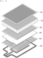
- FIG. 2 is an external perspective view of a battery module according to a preferred embodiment of the present invention
- FIG. 3 is an exploded perspective view of the interior of the battery module shown in FIG. 2 .
- the battery module according to the present invention includes a module case 100, a cylindrical battery cell 200, a heat sink 300, an insulation layer 400, an adhesive layer 500, and a module frame 600.
- the module case 100 which has an approximately hexahedral external shape, includes an upper case 110 and a lower case 120.
- the lower case 120 is constituted by a flat bottom and a side portion extending upwards perpendicularly from the edge of the bottom by a predetermined distance so as to provide a space portion having a predetermined size.
- the cylindrical battery cell 200, the heat sink 300, the insulation layer 400, the adhesive layer 500, and the module frame 600 are received in the space portion.
- the upper case 110 is coupled to an upper portion of the lower case 120 to protect the received cylindrical battery cell 200 and the like.
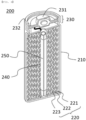
- FIG. 4 is a sectional view of the cylindrical battery cell mounted in the battery module according to the present invention.
- the cylindrical battery cell 200 may be manufactured by receiving a wound type electrode assembly 220 in a metal can 210, injecting an electrolytic solution into the metal can 210, and then coupling a cap assembly 230 having an electrode terminal formed thereon to the open upper end of the metal can 210.
- the electrode assembly 220 is manufactured by sequentially stacking a positive electrode 221, a negative electrode 222, and a separator 223 and winding the same so as to have a round shape.
- a cylindrical center pin 250 is inserted into a hollow core portion 240 formed at a central region of the electrode assembly 220.
- the center pin 250 is generally made of a metal material so as to have predetermined strength.
- the center pin 250 serves to fix and support the electrode assembly 220, and also serves as a passage configured to discharge gas generated as the result of internal reaction when the battery cell is charged and discharged and when the battery cell is operated.
- a positive electrode terminal 231 is formed on a central region of the upper end of the cap assembly 230 in a protruding state, and the remaining region of the metal can 210 forms a negative electrode terminal 232.
- a battery cell usable as a secondary battery is not limited to a cylindrical battery cell 200 having the above construction.
- heat is generated from the battery cell while the battery cell is repeatedly charged and discharged.
- the heat sink 300 is located between the inner bottom surface of the lower case 120 and the cylindrical battery cell 200.
- the heat sink 300 is configured to have a structure in which a lower plate and an upper plate are spaced apart from each other by a predetermined distance so as to form a space portion therebetween, the space portion is filled with a refrigerant, such as water or ethanol, in the state in which the refrigerant is circulated. Consequently, heat generated from the cylindrical battery cell 200 is transferred to the refrigerant, whereby the cylindrical battery cell is maintained at a predetermined temperature.
- a refrigerant such as water or ethanol
- the heat sink 300 may be made of a material that exhibits high thermal conductivity so as to rapidly transfer heat, such as aluminum. Also, in order to circulate the refrigerant, the heat sink may be provided at one side thereof with a refrigerant inlet and may be provided at the other side thereof with a refrigerant outlet.
- the insulation layer 400 is located on the upper surface of the heat sink 300 to prevent electrical conduction between the cylindrical battery cell 200 and the heat sink 300.
- the insulation layer 400 may be formed using a 3D printer.
- a 3D printer When an insulation material is discharged onto the upper surface of the heat sink 300 through a nozzle of the 3D printer, it is possible to form the insulation layer 400 on the upper surface of the heat sink 300 in a state of being fixed to the upper surface of the heat sink in tight contact therewith. Consequently, no separate adhesive member configured to fix the insulation layer 400 is necessary.
- the insulation layer 400 may be formed as the result of long bars, each of which has a circular or polygonal section, being fixed to the upper surface of the heat sink 300 in a state of being spaced apart from each other by a predetermined distance.
- the material for the insulation layer 400 is not particularly restricted as long as the material exhibits not only an insulation property but also thermal conductivity
- the material for the insulation layer may be polycarbonate, acrylonitrile butadiene styrene (ABS), or polycarbonate-acrylonitrile butadiene styrene (PC-ABS).
- the adhesive layer 500 is located between the cylindrical battery cell 200 and the insulation layer 400 such that the cylindrical battery cell 200 is fixed to the insulation layer 400.
- a liquid type adhesive may be applied to the upper surface of the insulation layer 400 to form a single adhesive layer 500.
- the adhesive layer 500 which is made of a material having thermal conductivity and heat resistance so as to transfer heat from the cylindrical battery cell 200 to the insulation layer 400 while not losing adhesive force at a high temperature, may be made of at least one of hardenable grease and epoxy-based adhesive glue.
- the material for the adhesive layer is not particularly restricted as long as the material is capable of perform the above functions.
- the module frame 600 which is seated on the upper side of the cylindrical battery cell 200, includes a busbar 610, a protrusion 620, and an opening 630 configured to expose the upper surface of the cylindrical battery cell 200.
- the module frame performs a function of protecting cylindrical battery cells 200 from external impact while connecting the cylindrical battery cells to each other in parallel or in series.
- FIG. 5 is a view showing various patterns of an insulation layer according to a preferred embodiment of the present invention.
- the insulation layer according to the present invention may have any of shapes shown in (a) to (c) of FIG. 5 .
- the insulation layer 400 of (a) of FIG. 5 is configured to have a structure in which hollow triangles each having a predetermined height are disposed side by side in a state of being spaced apart from each other.
- the triangles are hollow while insulation between the cylindrical battery cell 200 and the heat sink 300 is securely guaranteed, whereby it is possible to reduce the weight of the battery module and to reduce raw material cost.
- the insulation layer is shown as having a triangular structure in (a) of FIG. 5 , which is merely an illustration, the insulation layer may have a polygonal structure, such as a quadrangular structure, a pentagonal structure, or a hexagonal structure.
- FIG. 5 shows a hollow cylindrical shape instead of the triangular shape, and (c) of FIG. 5 shows a lattice structure.
- a plurality of different shapes such as triangles and circles or quadrangles and circles, may be mixed with each other to form the insulation layer 400.
- a battery module manufacturing method includes (S1) a step of forming an insulation layer 400 on the upper surface of a heat sink 300, (S2) a step of forming an adhesive layer 500 on the upper surface of the insulation layer 400, and (S3) a step of seating a plurality of cylindrical battery cells 200 on the upper surface of the adhesive layer 500.
- the predetermined pattern is formed on the upper surface of the heat sink 300 to prepare the insulation layer 400.
- the predetermined pattern is formed using a 3D printer.
- (S2) the step of forming the adhesive layer 500 on the upper surface of the insulation layer 400, the adhesive layer 500 is located on the upper surface of the insulation layer 400 in the state in which the upper surface of the heat sink 300 and the lower surface of the insulation layer 400 are attached to each other.
- the adhesive layer 500 may be formed by seating a film having adhesives applied to opposite surfaces thereof on the upper surface of the insulation layer or by applying a liquid type adhesive to the upper surface of the insulation layer.
- the plurality of cylindrical battery cells 200 is fixed to the adhesive layer 500 through (S3) the step of seating the cylindrical battery cells 200 on the upper surface of the adhesive layer 500.
- a module frame 600 is coupled to the upper parts of the cylindrical battery cells 200.
- the heat sink 300 may be received in a lower case 120 first before steps S1 to S3, it is preferable for (S1) the step of forming the insulation layer 400 on the upper surface of the heat sink 300 to be performed before the heat sink is received in the lower case 120 such that the insulation layer 400 is easily formed using the 3D printer.
- the present invention may provide a battery pack having the battery module received therein.
- the battery pack may be mounted in a device.
- the device may be an electronic device including a large-capacity battery, such as an electric vehicle, a hybrid electric vehicle, or a plug-in hybrid electric vehicle.
Abstract
The present invention relates to a battery module with improved cooling performance and a method of manufacturing the same, and more particularly to a battery module with improved cooling performance, the battery module including a plurality of cylindrical battery cells (200), a module frame (600) configured to electrically connect the cylindrical battery cells (200) to each other, a heat sink (300) located under the cylindrical battery cells (200), and an insulation layer (400) formed on the upper surface of the heat sink (300) in tight contact with the heat sink and a method of manufacturing the same.
Description
- This application claims the benefit of priority to
Korean Patent Application No. 2020-0105019 filed on August 21, 2020 - The present invention relates to a battery module with improved cooling performance and a method of manufacturing the same, and more particularly to a battery module configured such that an insulation layer located between a heat sink and a battery cell is fixed to one surface of the heat sink without a separate adhesive member, whereby cooling performance is improved and manufacturing cost is reduced, and a method of manufacturing the same.
- With recent development of alternative energies due to air pollution and energy depletion caused as the result of use of fossil fuels, demand for secondary batteries capable of storing electrical energy that is produced has increased. The secondary batteries, which are being capable of being charged and discharged, are intimately used in daily life. For example, the secondary batteries are used in mobile devices, electric vehicles, and hybrid electric vehicles.
- Required capacities of secondary batteries used as energy sources of various kinds of electronic devices inevitably used in modern society have been increased due to an increase in usage of mobile devices, increasing complexity of the mobile devices, and development of electric vehicles. In order to satisfy demand of users, a plurality of battery cells is disposed in a small-sized device, whereas a battery module including a plurality of battery cells electrically connected to each other or a battery pack including a plurality of battery modules is used in a vehicle.
- Meanwhile, although a secondary battery has excellent electrical properties, components constituting the battery, such as an active material or an electrolyte, are decomposed in an abnormal operation state, such as overcharging, overdischarging, exposure to high temperature, or electrical short circuit, whereby heat and gas are generated. As a result, a swelling phenomenon, i.e. expansion of the secondary battery, occurs. The swelling phenomenon accelerates decomposition, which causes explosion or ignition of the secondary battery due to thermal runaway.
-
FIG. 1 is an exploded perspective view of a conventional battery module. As shown inFIG. 1 , the conventional battery module includes a plurality ofcylindrical battery cells 10, aheat sink 20 located under the plurality ofcylindrical battery cells 10, aninsulation layer 30 located between thecylindrical battery cells 10 and theheat sink 20 so as to maintain insulation therebetween, and amodule frame 40 configured to cover the upper parts of the plurality ofcylindrical battery cells 10.Adhesive layers 50 are interposed between thecylindrical battery cells 10 and theinsulation layer 30 and between theheat sink 20 and theinsulation layer 30 in order to achieve fixing therebetween. - In the conventional battery module, heat generated from the
cylindrical battery cells 10 is removed by theheat sink 20 located under the cylindrical battery cells. Since theinsulation layer 30 and the pair ofadhesive layers 50 are provided between thecylindrical battery cells 10 and theheat sink 20, however, heat transfer efficiency is low. - Furthermore, in a battery module manufacturing process, the
adhesive layers 50 must be formed twice in order to fix theheat sink 20 and theinsulation layer 30 to each other and to fix theinsulation layer 30 and thecylindrical battery cells 10 to each other, whereby manufacturing cost is increased while manufacturing process efficiency is reduced. - The present invention has been made in view of the above problems, and it is an object of the present invention to provide a battery module with improved cooling performance configured such that the distance between a cylindrical battery cell and a heat sink is minimized and a method of manufacturing the same.
- It is another object of the present invention to provide a battery module with improved cooling performance configured such that the amount of raw material that is used is reduced, whereby manufacturing cost is reduced, and a manufacturing process is simplified, whereby productivity is improved, and a method of manufacturing the same.
- In order to accomplish the above objects, a battery module with improved cooling performance according to the present invention may include a plurality of cylindrical battery cells (200), a module frame (600) configured to electrically connect the plurality of cylindrical battery cells (200) to each other, a heat sink (300) located under the plurality of cylindrical battery cells (200), and an insulation layer (400) formed on the upper surface of the heat sink (300) and in tight contact with the heat sink.
- Also, in the battery module according to the present invention, an adhesive layer (500) may be located between lower surfaces of the plurality of cylindrical battery cells (200) and the insulation layer (400).
- Also, in the battery module according to the present invention, the insulation layer (400) may include a material having an insulation property and thermal conductivity.
- Also, in the battery module according to the present invention, the insulation layer (400) may have a predetermined pattern.
- Also, in the battery module according to the present invention, the pattern may be a lattice pattern.
- Also, in the battery module according to the present invention, the pattern may be constituted by a plurality of polygons spaced apart from each other by a predetermined distance.
- Also, in the battery module according to the present invention, the pattern may be constituted by a plurality of circles or a plurality of ovals.
- Also, in the battery module according to the present invention, the pattern may be constituted by a plurality of bars spaced apart from each other by a predetermined distance.
- Also, in the battery module according to the present invention, the adhesive layer (500) may include at least one of hardenable grease and epoxy-based adhesive glue.
- In addition, a battery pack including the battery module may be provided.
- In addition, a battery module manufacturing method according to the present invention includes forming an insulation layer (400) on the upper surface of a heat sink (300), forming an adhesive layer (500) on the upper surface of the insulation layer (400), and seating a plurality of cylindrical battery cells (200) on the upper surface of the adhesive layer (500).
- Also, in the battery module manufacturing method according to the present invention, the insulation layer (400) may be formed using a 3D printer.
- As is apparent from the above description, a battery module with improved cooling performance according to the present invention and a method of manufacturing the same have an advantage in that an insulation layer is fixed to a heat sink in tight contact therewith without a separate adhesive member, whereby heat generated from a cylindrical battery cell is rapidly transferred to the heat sink, and therefore it is possible to improve cooling performance.
- In addition, the battery module with improved cooling performance according to the present invention and the method of manufacturing the same have a merit in that the insulation layer is fixed to the heat sink in tight contact therewith using a 3D printer, whereby it is possible to reduce the amount of the adhesive member that is used, and therefore it is possible to reduce manufacturing cost and to improve manufacturing process efficiency.
- Furthermore, the battery module with improved cooling performance according to the present invention and the method of manufacturing the same have an advantage in that it is possible to freely adjust the thickness, area, and shape of the insulation layer through setting of the path of the 3D printer and adjustment of the output speed thereof.
-
-
FIG. 1 is an exploded perspective view of a conventional battery module. -
FIG. 2 is an external perspective view of a battery module according to a preferred embodiment of the present invention. -
FIG. 3 is an exploded perspective view of the interior of the battery module shown inFIG. 2 . -
FIG. 4 is a sectional view of a cylindrical battery cell mounted in the battery module according to the present invention. -
FIG. 5 is a view showing various patterns of an insulation layer according to a preferred embodiment of the present invention. - Now, preferred embodiments of the present invention will be described in detail with reference to the accompanying drawings such that the preferred embodiments of the present invention can be easily implemented by a person having ordinary skill in the art to which the present invention pertains. In describing the principle of operation of the preferred embodiments of the present invention in detail, however, a detailed description of known functions and configurations incorporated herein will be omitted when the same may obscure the subject matter of the present invention.
- In addition, the same reference numbers will be used throughout the drawings to refer to parts that perform similar functions or operations. In the case in which one part is said to be connected to another part in the entire specification, not only may the one part be directly connected to the other part, but also, the one part may be indirectly connected to the other part via a further part. In addition, that a certain element is included does not mean that other elements are excluded, but means that such elements may be further included unless mentioned otherwise.
- Hereinafter, a battery module with improved cooling performance according to the present invention and a method of manufacturing the same will be described with reference to the accompanying drawings.
-
FIG. 2 is an external perspective view of a battery module according to a preferred embodiment of the present invention, andFIG. 3 is an exploded perspective view of the interior of the battery module shown inFIG. 2 . - Referring to
FIGS. 2 and3 , the battery module according to the present invention includes amodule case 100, acylindrical battery cell 200, aheat sink 300, aninsulation layer 400, anadhesive layer 500, and amodule frame 600. - First, the
module case 100, which has an approximately hexahedral external shape, includes anupper case 110 and alower case 120. Thelower case 120 is constituted by a flat bottom and a side portion extending upwards perpendicularly from the edge of the bottom by a predetermined distance so as to provide a space portion having a predetermined size. Thecylindrical battery cell 200, theheat sink 300, theinsulation layer 400, theadhesive layer 500, and themodule frame 600 are received in the space portion. Theupper case 110 is coupled to an upper portion of thelower case 120 to protect the receivedcylindrical battery cell 200 and the like. -
FIG. 4 is a sectional view of the cylindrical battery cell mounted in the battery module according to the present invention. Thecylindrical battery cell 200 may be manufactured by receiving a woundtype electrode assembly 220 in a metal can 210, injecting an electrolytic solution into the metal can 210, and then coupling acap assembly 230 having an electrode terminal formed thereon to the open upper end of the metal can 210. - Here, the
electrode assembly 220 is manufactured by sequentially stacking apositive electrode 221, anegative electrode 222, and aseparator 223 and winding the same so as to have a round shape. - A
cylindrical center pin 250 is inserted into ahollow core portion 240 formed at a central region of theelectrode assembly 220. Thecenter pin 250 is generally made of a metal material so as to have predetermined strength. Thecenter pin 250 serves to fix and support theelectrode assembly 220, and also serves as a passage configured to discharge gas generated as the result of internal reaction when the battery cell is charged and discharged and when the battery cell is operated. - Meanwhile, a
positive electrode terminal 231 is formed on a central region of the upper end of thecap assembly 230 in a protruding state, and the remaining region of the metal can 210 forms anegative electrode terminal 232. - Of course, a battery cell usable as a secondary battery is not limited to a
cylindrical battery cell 200 having the above construction. - Referring back to
FIG. 3 , heat is generated from the battery cell while the battery cell is repeatedly charged and discharged. In order to remove the heat, theheat sink 300 is located between the inner bottom surface of thelower case 120 and thecylindrical battery cell 200. - Although not shown in detail in the figure, the
heat sink 300 is configured to have a structure in which a lower plate and an upper plate are spaced apart from each other by a predetermined distance so as to form a space portion therebetween, the space portion is filled with a refrigerant, such as water or ethanol, in the state in which the refrigerant is circulated. Consequently, heat generated from thecylindrical battery cell 200 is transferred to the refrigerant, whereby the cylindrical battery cell is maintained at a predetermined temperature. - Here, the
heat sink 300 may be made of a material that exhibits high thermal conductivity so as to rapidly transfer heat, such as aluminum. Also, in order to circulate the refrigerant, the heat sink may be provided at one side thereof with a refrigerant inlet and may be provided at the other side thereof with a refrigerant outlet. - The
insulation layer 400 is located on the upper surface of theheat sink 300 to prevent electrical conduction between thecylindrical battery cell 200 and theheat sink 300. - Specifically, the
insulation layer 400 may be formed using a 3D printer. When an insulation material is discharged onto the upper surface of theheat sink 300 through a nozzle of the 3D printer, it is possible to form theinsulation layer 400 on the upper surface of theheat sink 300 in a state of being fixed to the upper surface of the heat sink in tight contact therewith. Consequently, no separate adhesive member configured to fix theinsulation layer 400 is necessary. - Furthermore, repetitive stacking is possible in the case in which a stacking type printing method is used. Consequently, it is possible to easily adjust the thickness of the
insulation layer 400 and to implement various three-dimensional patterns. As an example, as shown inFIG. 3 , theinsulation layer 400 may be formed as the result of long bars, each of which has a circular or polygonal section, being fixed to the upper surface of theheat sink 300 in a state of being spaced apart from each other by a predetermined distance. - Meanwhile, although the material for the
insulation layer 400 is not particularly restricted as long as the material exhibits not only an insulation property but also thermal conductivity, the material for the insulation layer may be polycarbonate, acrylonitrile butadiene styrene (ABS), or polycarbonate-acrylonitrile butadiene styrene (PC-ABS). - The
adhesive layer 500 is located between thecylindrical battery cell 200 and theinsulation layer 400 such that thecylindrical battery cell 200 is fixed to theinsulation layer 400. - A liquid type adhesive may be applied to the upper surface of the
insulation layer 400 to form a singleadhesive layer 500. - Here, the
adhesive layer 500, which is made of a material having thermal conductivity and heat resistance so as to transfer heat from thecylindrical battery cell 200 to theinsulation layer 400 while not losing adhesive force at a high temperature, may be made of at least one of hardenable grease and epoxy-based adhesive glue. However, the material for the adhesive layer is not particularly restricted as long as the material is capable of perform the above functions. - The
module frame 600, which is seated on the upper side of thecylindrical battery cell 200, includes abusbar 610, aprotrusion 620, and anopening 630 configured to expose the upper surface of thecylindrical battery cell 200. The module frame performs a function of protectingcylindrical battery cells 200 from external impact while connecting the cylindrical battery cells to each other in parallel or in series. -
FIG. 5 is a view showing various patterns of an insulation layer according to a preferred embodiment of the present invention. The insulation layer according to the present invention may have any of shapes shown in (a) to (c) ofFIG. 5 . - First, the
insulation layer 400 of (a) ofFIG. 5 is configured to have a structure in which hollow triangles each having a predetermined height are disposed side by side in a state of being spaced apart from each other. In the structure of theinsulation layer 400, the triangles are hollow while insulation between thecylindrical battery cell 200 and theheat sink 300 is securely guaranteed, whereby it is possible to reduce the weight of the battery module and to reduce raw material cost. Meanwhile, although the insulation layer is shown as having a triangular structure in (a) ofFIG. 5 , which is merely an illustration, the insulation layer may have a polygonal structure, such as a quadrangular structure, a pentagonal structure, or a hexagonal structure. - (b) of
FIG. 5 shows a hollow cylindrical shape instead of the triangular shape, and (c) ofFIG. 5 shows a lattice structure. - Although the same shapes are shown as being repeatedly arranged in
FIG. 5 , a plurality of different shapes, such as triangles and circles or quadrangles and circles, may be mixed with each other to form theinsulation layer 400. - Hereinafter, a method of manufacturing the battery module according to the preferred embodiment of the present invention described above will be described.
- A battery module manufacturing method according to a preferred embodiment of the present invention includes (S1) a step of forming an
insulation layer 400 on the upper surface of aheat sink 300, (S2) a step of forming anadhesive layer 500 on the upper surface of theinsulation layer 400, and (S3) a step of seating a plurality ofcylindrical battery cells 200 on the upper surface of theadhesive layer 500. - Specifically, in (S1) the step of forming the
insulation layer 400 on the upper surface of theheat sink 300, the predetermined pattern is formed on the upper surface of theheat sink 300 to prepare theinsulation layer 400. At this time, the predetermined pattern is formed using a 3D printer. - It is possible to freely adjust the thickness, area, and pattern of the
insulation layer 400 by setting the output speed and path of the 3D printer. - In (S2) the step of forming the
adhesive layer 500 on the upper surface of theinsulation layer 400, theadhesive layer 500 is located on the upper surface of theinsulation layer 400 in the state in which the upper surface of theheat sink 300 and the lower surface of theinsulation layer 400 are attached to each other. - Here, the
adhesive layer 500 may be formed by seating a film having adhesives applied to opposite surfaces thereof on the upper surface of the insulation layer or by applying a liquid type adhesive to the upper surface of the insulation layer. - The plurality of
cylindrical battery cells 200 is fixed to theadhesive layer 500 through (S3) the step of seating thecylindrical battery cells 200 on the upper surface of theadhesive layer 500. - Of course, a
module frame 600 is coupled to the upper parts of thecylindrical battery cells 200. - Meanwhile, although the
heat sink 300 may be received in alower case 120 first before steps S1 to S3, it is preferable for (S1) the step of forming theinsulation layer 400 on the upper surface of theheat sink 300 to be performed before the heat sink is received in thelower case 120 such that theinsulation layer 400 is easily formed using the 3D printer. - The present invention may provide a battery pack having the battery module received therein. In addition, the battery pack may be mounted in a device. For example, the device may be an electronic device including a large-capacity battery, such as an electric vehicle, a hybrid electric vehicle, or a plug-in hybrid electric vehicle.
- Although the specific details of the present invention have been described in detail, those skilled in the art will appreciate that the detailed description thereof discloses only preferred embodiments of the present invention and thus does not limit the scope of the present invention. Accordingly, those skilled in the art will appreciate that various changes and modifications are possible, without departing from the category and the technical idea of the present invention, and it will be obvious that such changes and modifications fall within the scope of the appended claims.
-
- 100: Module case
- 110: Upper case
- 120: Lower case
- 200: Cylindrical battery cell
- 210: Metal can
- 220: Electrode assembly
- 221: Positive electrode 222: Negative electrode
- 223: Separator
- 230: Cap assembly
- 231: Positive electrode terminal 232: Negative electrode terminal
- 240: Core portion
- 250: Center pin
- 300: Heat sink
- 400: Insulation layer
- 500: Adhesive layer
- 600: Module frame
- 610: Busbar
- 620: Protrusion
- 630: Opening
Claims (12)
- A battery module with improved cooling performance, the battery module comprising:a plurality of cylindrical battery cells;a module frame configured to electrically connect the plurality of cylindrical battery cells to each other;a heat sink located under the plurality of cylindrical battery cells; andan insulation layer formed on an upper surface of the heat sink and in tight contact with the heat sink.
- The battery module according to claim 1, further comprising an adhesive layer located between lower surfaces of the plurality of cylindrical battery cells and the insulation layer.
- The battery module according to claim 1, wherein the insulation layer includes a material having an insulation property and thermal conductivity.
- The battery module according to claim 1, wherein the insulation layer has a predetermined pattern.
- The battery module according to claim 4, wherein the pattern is a lattice pattern.
- The battery module according to claim 4, wherein the pattern is constituted by a plurality of polygons spaced apart from each other by a predetermined distance.
- The battery module according to claim 4, wherein the pattern is constituted by a plurality of circles or a plurality of ovals.
- The battery module according to claim 4, wherein the pattern is constituted by a plurality of bars spaced apart from each other by a predetermined distance.
- The battery module according to claim 2, wherein the adhesive layer includes at least one of hardenable grease and epoxy-based adhesive glue.
- A battery pack comprising the battery module according to any one of claims 1 to 9.
- A method of manufacturing a battery module with improved cooling performance, the method comprising:forming an insulation layer on an upper surface of a heat sink;forming an adhesive layer on an upper surface of the insulation layer; andseating a plurality of cylindrical battery cells on an upper surface of the adhesive layer.
- The method according to claim 11, wherein the insulation layer is formed using a 3D printer.
Applications Claiming Priority (2)
| Application Number | Priority Date | Filing Date | Title |
|---|---|---|---|
| KR1020200105019A KR20220023366A (en) | 2020-08-21 | 2020-08-21 | Battery Module With Improved Cooling Performance and Method of Manufacturing the Same |
| PCT/KR2021/010914 WO2022039477A1 (en) | 2020-08-21 | 2021-08-18 | Battery module with improved cooling performance and manufacturing method thereof |
Publications (1)
| Publication Number | Publication Date |
|---|---|
| EP4203145A1 true EP4203145A1 (en) | 2023-06-28 |
Family
ID=80350519
Family Applications (1)
| Application Number | Title | Priority Date | Filing Date |
|---|---|---|---|
| EP21858564.4A Pending EP4203145A1 (en) | 2020-08-21 | 2021-08-18 | Battery module with improved cooling performance and manufacturing method thereof |
Country Status (6)
| Country | Link |
|---|---|
| US (1) | US20230128584A1 (en) |
| EP (1) | EP4203145A1 (en) |
| JP (1) | JP2023521905A (en) |
| KR (1) | KR20220023366A (en) |
| CN (1) | CN115428234A (en) |
| WO (1) | WO2022039477A1 (en) |
Family Cites Families (6)
| Publication number | Priority date | Publication date | Assignee | Title |
|---|---|---|---|---|
| US9397376B2 (en) * | 2014-09-25 | 2016-07-19 | Atieva, Inc. | Battery pack with segmented, electrically isolated heat sink |
| CN204230382U (en) * | 2014-10-31 | 2015-03-25 | 比亚迪股份有限公司 | A kind of heating panel and electrokinetic cell system |
| KR101738037B1 (en) * | 2015-05-20 | 2017-05-19 | 희성정밀 주식회사 | A Heat Sink for Air Cooling Battery, Manufacturing Method Thereof and Cooling Apparatus with Heat Sink for Air Cooling Battery |
| US10374272B1 (en) * | 2015-11-04 | 2019-08-06 | Boston Dynamics, Inc. | Battery thermal management system |
| KR102112716B1 (en) * | 2016-03-16 | 2020-05-19 | 주식회사 엘지화학 | Battery module, battery pack the battery module and vehicle comprising the battery pack |
| KR20200105019A (en) | 2019-02-28 | 2020-09-07 | 민웅재 | Apparatus for injecting medical yarn |
-
2020
- 2020-08-21 KR KR1020200105019A patent/KR20220023366A/en active Search and Examination
-
2021
- 2021-08-18 EP EP21858564.4A patent/EP4203145A1/en active Pending
- 2021-08-18 CN CN202180026543.9A patent/CN115428234A/en active Pending
- 2021-08-18 US US17/915,877 patent/US20230128584A1/en active Pending
- 2021-08-18 WO PCT/KR2021/010914 patent/WO2022039477A1/en unknown
- 2021-08-18 JP JP2022562860A patent/JP2023521905A/en active Pending
Also Published As
| Publication number | Publication date |
|---|---|
| JP2023521905A (en) | 2023-05-25 |
| KR20220023366A (en) | 2022-03-02 |
| CN115428234A (en) | 2022-12-02 |
| WO2022039477A1 (en) | 2022-02-24 |
| US20230128584A1 (en) | 2023-04-27 |
Similar Documents
| Publication | Publication Date | Title |
|---|---|---|
| KR101238060B1 (en) | Assembled battery, and vehicle equipped with the assembled battery | |
| JP4652415B2 (en) | Battery cartridge having a novel structure and an open battery module including the same | |
| KR101965373B1 (en) | Cylindrical Battery Module | |
| EP3624214B1 (en) | Cylindrical secondary battery module and method for producing cylindrical secondary battery module | |
| CN108701793B (en) | Battery pack | |
| KR101252963B1 (en) | Battery pack with enhanced radiating ability | |
| EP3446346B1 (en) | Multicavity battery module | |
| JP5344237B2 (en) | Assembled battery | |
| EP4181275A1 (en) | Battery module and battery pack including same | |
| EP4203145A1 (en) | Battery module with improved cooling performance and manufacturing method thereof | |
| CN115172979A (en) | Battery module, battery and power consumption device | |
| EP3972039A1 (en) | Cell module assembly and method for manufacturing same | |
| CN116745977A (en) | Battery, electric device, method and equipment for preparing battery | |
| KR101514426B1 (en) | Connector, battery pack having the same and assembling method thereof | |
| JP2002373633A (en) | Battery pack | |
| KR101073012B1 (en) | Cap assembly, secondary battery and module thereof | |
| CN216720084U (en) | Battery monomer, battery and consumer | |
| KR102598670B1 (en) | Battery module | |
| CN220121952U (en) | Battery module and battery pack including the same | |
| US11961956B2 (en) | Cylindrical secondary battery module and method for producing cylindrical secondary battery module | |
| CN116864600A (en) | Electrode assembly, battery cell, battery and electricity utilization device | |
| KR20230122170A (en) | Batteries, electrical equipment, manufacturing methods and equipment for batteries | |
| CN117296194A (en) | Battery cell, battery module, battery and electricity utilization device | |
| CN116802878A (en) | Battery cell, battery, electric equipment, method and equipment for preparing battery | |
| CN115769418A (en) | Battery module and battery pack including the same |
Legal Events
| Date | Code | Title | Description |
|---|---|---|---|
| STAA | Information on the status of an ep patent application or granted ep patent |
Free format text: STATUS: THE INTERNATIONAL PUBLICATION HAS BEEN MADE |
|
| PUAI | Public reference made under article 153(3) epc to a published international application that has entered the european phase |
Free format text: ORIGINAL CODE: 0009012 |
|
| STAA | Information on the status of an ep patent application or granted ep patent |
Free format text: STATUS: REQUEST FOR EXAMINATION WAS MADE |
|
| 17P | Request for examination filed |
Effective date: 20221005 |
|
| AK | Designated contracting states |
Kind code of ref document: A1 Designated state(s): AL AT BE BG CH CY CZ DE DK EE ES FI FR GB GR HR HU IE IS IT LI LT LU LV MC MK MT NL NO PL PT RO RS SE SI SK SM TR |
|
| DAV | Request for validation of the european patent (deleted) | ||
| DAX | Request for extension of the european patent (deleted) |