EP4047584A1 - Notdurchgangssystem - Google Patents
Notdurchgangssystem Download PDFInfo
- Publication number
- EP4047584A1 EP4047584A1 EP21158143.4A EP21158143A EP4047584A1 EP 4047584 A1 EP4047584 A1 EP 4047584A1 EP 21158143 A EP21158143 A EP 21158143A EP 4047584 A1 EP4047584 A1 EP 4047584A1
- Authority
- EP
- European Patent Office
- Prior art keywords
- visual warning
- wireless communications
- communications module
- emergency
- passage system
- Prior art date
- Legal status (The legal status is an assumption and is not a legal conclusion. Google has not performed a legal analysis and makes no representation as to the accuracy of the status listed.)
- Withdrawn
Links
Images
Classifications
-
- G—PHYSICS
- G08—SIGNALLING
- G08G—TRAFFIC CONTROL SYSTEMS
- G08G1/00—Traffic control systems for road vehicles
- G08G1/07—Controlling traffic signals
- G08G1/087—Override of traffic control, e.g. by signal transmitted by an emergency vehicle
Definitions
- the present invention relates to an emergency passage system.
- An example of such a system is disclosed in US9934685 , which is incorporated in the present disclosure by reference.
- the stand-alone system may send information to a central server, but it is not a requirement.
- An emergency passage system for notification of an approaching emergency vehicle comprising:
- a city may have three intersections.
- the traffic load at two of the intersections may be much higher than the traffic load at the third.
- the emergency passage system may be constituted by a first visual warning device and a first wireless communications module at the first heavy loaded intersection, and a second visual warning device and a second wireless communications module at the second heavy loaded intersection.
- a city may have three intersections. All three intersections may have a high traffic load, but two of them may be close to each other.
- the emergency passage system may be constituted by a first visual warning device and a first wireless communications module at the first intersection, and a second visual warning device at the second intersection and a third visual warning device at the third intersection.
- the second and third visual warning device may be controlled by one wireless communications module.
- a given infrastructure may comprise a plurality of intersections, and all or at least some of these intersections may comprise a system having a wireless communications module and a visual warning device.
- the system may also have at least one central processing unit controlling the wireless communications module and the visual warning device.
- the system at an intersection may be battery and/or solar powered. It may comprise means for communication to a central server for surveillance of the system, for example via a sim card. If the battery is running low or an otherwise defect is detected, it may be communicated to the central server such that the defect may be fixed.
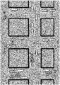
- Fig. 1 shows an overview of a traffic situation in which an emergency passage system is arranged to facilitate movement of an emergency vehicle through traffic.
- the emergency vehicle may arrive sooner at a scene of an accident or arrive sooner at a hospital for example.
- the emergency vehicle may be an ambulance, a police car or fire truck a tow truck for example.
- the overview shows six intersections.
- a visual warning device is arranged at each intersection, i.e. six visual warning devices are illustrated. Each visual warning device is illustrated as a dotted circle.
- a first visual warning device 10 is arranged in a first intersection, i.e. arranged at the center of the first intersection. Six vehicles are approaching the first intersection.
- the first intersection may have a traffic light for regulating the flow of traffic through the first intersection, such that cars on the first road of the first intersection have a green light, and the cars on the other road of the first intersection have a red light.
- Each visual warning device is connected to a wireless communications module, i.e. the first visual warning device is connected to a first wireless communications module.
- the first wireless communications module may be arranged together with the first visual warning device or at a corner of the intersection.
- connection between the first wireless communications module and the first visual warning device may be wired or wireless.
- Each wireless communications module has a directivity and a signal threshold defining an activation zone, i.e. the first wireless communications module defines a first activation zone 12.
- a four-way intersection such as the first intersection in fig. 1 is to have an activation zone for each of the four-road segment. This may be achieved with a wireless communications module with four directional antennas.
- a three-way intersection may have a wireless communications module with three directional antennas.
- the wireless communications module of the emergency vehicle in an emergency state may define an activation zone, i.e. as the emergency vehicle moves through traffic and a wireless communication module at an intersection is within the activation zone of the emergency vehicle, the visual warning device is switched on.
- the wireless communication module of the emergency vehicle may be arranged to transmit a wireless signal in the direction of travel, for example by means of a directive antenna.
- the wireless communications module may transmit with a signal strength such that it may travel a distance corresponding to the average distance between intersections of the city and be detected by a wireless communication module of an intersection.
- the first wireless communications module defines four activations zones (12a, 12b, 12c, 12d) for example by means of up to four antennas.
- the activation zone is for detecting an approaching emergency vehicle - when an emergency vehicle is inside the activation zone, a wireless signal transmitted from the emergency vehicle may be detected.
- the first visual warning device 10 displays a first visual warning, for example a blue light.
- the first wireless communications module may have a directional antenna that may be adjusted to a first direction, for example down the road of one of the roads of the intersection, i.e. the directivity may be adjusted to an angle range within 0 to 120 degrees depending on the course of the road, for example if it is a an one lane road or a two lane road.
- the gain of the first wireless communications module may be such that a signal from outside the angle range is noise and is not registered as a signal from an emergency vehicle.
- the signal threshold of the first wireless communications module may be adjusted for example in dependance on the distance to the next intersection, i.e. such that a signal from a greater distance is noise and is not registered as a signal from an emergency vehicle. In this way, only a relevant visual warning device is activated, and the traffic at other intersections is not disrupted.
- a wireless signal transmitted from the emergency vehicle may be transmitted at a fixed signal level.
- the strength of the electric field associated with the first wireless communications module decreases with distance to the first wireless communications module, for example approximated by the function 1/d, where d is the distance to the first wireless communications module.
- the amplification by the first wireless communications module may then be set as a function of the signal level of the wireless signal from the emergency vehicle, and the distance between two intersections, such that when the emergency vehicle enters the zone between two intersections, i.e. the activation zone defined by the first wireless communications module, the wireless signal transmitted by the emergency vehicle is detected (even at the far end of the activation zone).
- the emergency vehicle emits a wireless signal at 4 dB.
- the distance to the wireless communications module at an intersection is so that the signal is attenuated 3 dB.
- the signal is 1 dB.
- the signal threshold of the wireless communication module is 2 dB. This means that the signal is not accepted, but rejected.
- the wireless signal transmitted by the emergency vehicle may be coded.
- a second visual warning device 14 is arranged at a second intersection.
- the second visual warning device is connected to a second wireless communications module.
- a first emergency vehicle 16a has entered the first activation zone 12a.
- the first emergency vehicle has a third visual warning device 17 displaying a blue light meaning that the first emergency vehicle is on route to an emergency.
- the first emergency vehicle has a third wireless communications module, which may be arranged to transmit a wireless signal for example by means of an antenna.
- Fig. 1 illustrates a radiation pattern 18 of the antenna.
- the third wireless communications module may be activated/switched on when the third visual warning device is switched on.
- the first wireless communications module may transmit a first wireless signal.
- the first wireless signal may be received by the third wireless communications module, because the third wireless communications module is on.
- the third wireless communications module may send a second wireless signal back to the first wireless communications module, and thereby switch on the first visual warning device.
- the third wireless communications module transmits a wireless signal continuously or in time intervals, and when the first emergency vehicle is within the first activation zone, the wireless signal is received by the first wireless communications module.
- the first visual warning device Since the first emergency vehicle is in an emergency state (its visual warning device is on), and the first emergency vehicle has entered the first activation zone, the first visual warning device displays a visual warning (a blue light).
- a second emergency vehicle 16b has entered the activation zone 15a defined by the second wireless communication module 14.
- the visual warning device of the second emergency vehicle is on.
- the second wireless communications module registers that an emergency vehicle in an emergency state is within one of its activation zones.
- a third emergency vehicle 16c is inside the activation zone 15d of the second wireless communications module.
- the third emergency vehicle being in an emergency state.
- two emergency vehicles in emergency states are approaching the same intersection.
- the visual warning device of that intersection displays another visual warning than the first visual warning. In fig. 1 it is illustrated that the second visual warning device displays a red light.
- a third emergency vehicle 16c is in the activation zone 15c.
- an emergency vehicle such as the emergency vehicle 16d
- an activation zone such as the activation zone 12b of the first wireless communications module
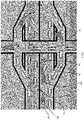
- Fig. 2 shows a highway situation including two intersections on a bridge across the highway.
- the flow of traffic for the two intersections on the bridge may be regulated using an emergency passage system as described in connection with fig. 1 .
- the emergency passage system may also be used to regulate the flow of traffic on the highway.
- visual warning devices are arranged, such as a first visual warning device 10 and a second visual warning device 14.
- the first visual warning device is connected to a first wireless communication module.
- the second visual warning device is connected to a second wireless communication module.
- the first wireless communication module defines a first activation zone 12a and the second wireless communication module defines an activation zone 15a.
- One wireless communication module could be used by (connected to) more than one visual warning device, i.e. when an emergency vehicle is detected by the wireless communication module, the wireless communication module can activate (switch on) successive visual warning devices depending on the velocity of the emergency vehicle.
- the visual warning devices are spaced a distance.
- the spacing is a balance between providing an efficient traffic low and facilitating movement of an emergency vehicle.
- a large distance between the visual warning devices means that there is a lower chance of the traffic on the highway becomes aware of an approaching emergency vehicle, but the traffic is cleared more efficient.
- a short distance between the visual warning devices means that there is a higher chance of the traffic on the highway becomes aware of an approaching emergency vehicle, but the traffic is cleared less efficient.
- a typical distance could be for example between 100 m to 2000 m, such as 300 to 1000 m.
- the distance between the first visual warning device and the second visual warning device is so that as the emergency vehicle 16a, which is in an emergency state, transmits a wireless signal detected by both the first wireless communication module and the second wireless communication module. Meaning that the first visual warning device and the second visual warning device display a visual warning (in the form of a blue light).
- Fig. 2 shows that a car 20 is clearing the road for the emergency vehicle by pulling to the right side of the road.
- the emergency vehicle 16a has a third visual warning device 17.
- a fourth visual warning device 19 is located at an entry to the highway.
- the entry may be regulated similar to the regulation of an intersection.
- the wireless communication module connected to the fourth visual warning may define an activation zone that also includes the entry.
- a second emergency vehicle 22 in an emergency state is entering the highway.
- the wireless communication module connected to the fourth visual warning detects the first emergency vehicle approaching.
- the fourth visual warning device display a visual warning in the form of a red light.
Landscapes
- Business, Economics & Management (AREA)
- Emergency Management (AREA)
- Physics & Mathematics (AREA)
- General Physics & Mathematics (AREA)
- Traffic Control Systems (AREA)
Priority Applications (4)
| Application Number | Priority Date | Filing Date | Title |
|---|---|---|---|
| EP21158143.4A EP4047584A1 (de) | 2021-02-19 | 2021-02-19 | Notdurchgangssystem |
| PCT/EP2022/054227 WO2022175517A1 (en) | 2021-02-19 | 2022-02-21 | An emergency passage system |
| EP22711500.3A EP4295337B1 (de) | 2021-02-19 | 2022-02-21 | Notdurchgangssystem |
| US18/287,360 US20240203250A1 (en) | 2021-02-19 | 2022-02-21 | An emergency passage system |
Applications Claiming Priority (1)
| Application Number | Priority Date | Filing Date | Title |
|---|---|---|---|
| EP21158143.4A EP4047584A1 (de) | 2021-02-19 | 2021-02-19 | Notdurchgangssystem |
Publications (1)
| Publication Number | Publication Date |
|---|---|
| EP4047584A1 true EP4047584A1 (de) | 2022-08-24 |
Family
ID=74672159
Family Applications (2)
| Application Number | Title | Priority Date | Filing Date |
|---|---|---|---|
| EP21158143.4A Withdrawn EP4047584A1 (de) | 2021-02-19 | 2021-02-19 | Notdurchgangssystem |
| EP22711500.3A Active EP4295337B1 (de) | 2021-02-19 | 2022-02-21 | Notdurchgangssystem |
Family Applications After (1)
| Application Number | Title | Priority Date | Filing Date |
|---|---|---|---|
| EP22711500.3A Active EP4295337B1 (de) | 2021-02-19 | 2022-02-21 | Notdurchgangssystem |
Country Status (3)
| Country | Link |
|---|---|
| US (1) | US20240203250A1 (de) |
| EP (2) | EP4047584A1 (de) |
| WO (1) | WO2022175517A1 (de) |
Citations (4)
| Publication number | Priority date | Publication date | Assignee | Title |
|---|---|---|---|---|
| US6940422B1 (en) * | 2002-08-15 | 2005-09-06 | California Institute Of Technology | Emergency vehicle traffic signal preemption system |
| US20130027221A1 (en) * | 2011-07-30 | 2013-01-31 | Ivay Johnson | Warning system for an intersection |
| US9934685B1 (en) | 2017-04-11 | 2018-04-03 | International Business Machines Corporation | Directional traffic notifications of approaching priority vehicles |
| WO2021007582A1 (en) * | 2019-07-11 | 2021-01-14 | Davis Jr Milton | Emergency vehicle warning indication system |
Family Cites Families (3)
| Publication number | Priority date | Publication date | Assignee | Title |
|---|---|---|---|---|
| US4228419A (en) * | 1978-08-09 | 1980-10-14 | Electronic Implementation Systems, Inc. | Emergency vehicle traffic control system |
| US6999724B2 (en) * | 2002-06-20 | 2006-02-14 | Lucent Technologies Inc. | Slowing the observed rate of channel fluctuations in a multiple antenna system |
| US20200126412A1 (en) * | 2018-10-19 | 2020-04-23 | Bradley James | Emergency vehicle proximity alert system |
-
2021
- 2021-02-19 EP EP21158143.4A patent/EP4047584A1/de not_active Withdrawn
-
2022
- 2022-02-21 WO PCT/EP2022/054227 patent/WO2022175517A1/en not_active Ceased
- 2022-02-21 EP EP22711500.3A patent/EP4295337B1/de active Active
- 2022-02-21 US US18/287,360 patent/US20240203250A1/en active Pending
Patent Citations (4)
| Publication number | Priority date | Publication date | Assignee | Title |
|---|---|---|---|---|
| US6940422B1 (en) * | 2002-08-15 | 2005-09-06 | California Institute Of Technology | Emergency vehicle traffic signal preemption system |
| US20130027221A1 (en) * | 2011-07-30 | 2013-01-31 | Ivay Johnson | Warning system for an intersection |
| US9934685B1 (en) | 2017-04-11 | 2018-04-03 | International Business Machines Corporation | Directional traffic notifications of approaching priority vehicles |
| WO2021007582A1 (en) * | 2019-07-11 | 2021-01-14 | Davis Jr Milton | Emergency vehicle warning indication system |
Also Published As
| Publication number | Publication date |
|---|---|
| EP4295337A1 (de) | 2023-12-27 |
| US20240203250A1 (en) | 2024-06-20 |
| EP4295337B1 (de) | 2026-04-08 |
| WO2022175517A1 (en) | 2022-08-25 |
Similar Documents
| Publication | Publication Date | Title |
|---|---|---|
| US20220147043A1 (en) | Autonomous vehicle mode regulator | |
| US11763670B2 (en) | Method of automatically controlling an autonomous vehicle based on electronic messages from roadside infrastructure or other vehicles | |
| JP7254517B2 (ja) | 自律ビークル牽引システムおよび方法 | |
| US9142127B1 (en) | Systems and methods for traffic guidance nodes and traffic navigating entities | |
| US6940422B1 (en) | Emergency vehicle traffic signal preemption system | |
| US7898432B2 (en) | System and method for determining intersection right-of-way for vehicles | |
| US20200111346A1 (en) | Vehicle-to-vehicle communication system, roadside communication apparatus, in-vehicle communication apparatus, and vehicle-to-vehicle communication method | |
| CN104937649B (zh) | 一种道路信息接收系统及接收方法 | |
| EP2881926A1 (de) | Verfahren und Steuersystem zur Steuerung der Bewegung einer Gruppe von Straßenfahrzeugen | |
| WO2018217774A1 (en) | Improved roadway guidance system | |
| US11626016B2 (en) | Systems and methods of vehicular operation | |
| US20200126412A1 (en) | Emergency vehicle proximity alert system | |
| KR102559481B1 (ko) | 자율주행 차가 혼재된 도로에서 교차로 사고 감소를 위한 신호 제어 시스템 및 방법 | |
| KR101350357B1 (ko) | 노변 장치 및 그 노변 장치를 이용한 교통신호 제어 방법 | |
| KR102400246B1 (ko) | 레이더를 이용한 보행자 도로 횡단 교통안전사고 예방 시스템 | |
| US20190096246A1 (en) | Compact modular wireless sensing radar infrastructure device | |
| CN105580061A (zh) | 一种道路信息接收系统及接收方法 | |
| US20240203250A1 (en) | An emergency passage system | |
| WO2019040024A2 (en) | SYSTEM AND METHOD FOR DIFFUSION BY ROUTING AND PROCESSING TRAFFIC WARNING INFORMATION TO ADVISE A DRIVER | |
| WO2021054915A1 (en) | Collision avoidance systems and methods for intersections with no traffic signals | |
| KR20180085600A (ko) | 교통신호등 제어 시스템 및 그 방법 | |
| KR20190048169A (ko) | 긴급상황 알림 시스템 | |
| RU2836728C2 (ru) | Способ информирования о пешеходе при пересечении им участка улично-дорожной сети по пешеходному переходу | |
| KR102658916B1 (ko) | 자율주행 차량 안전 지원 및 확장 시스템 | |
| CN105580060A (zh) | 一种道路信息接收系统及接收方法 |
Legal Events
| Date | Code | Title | Description |
|---|---|---|---|
| STAA | Information on the status of an ep patent application or granted ep patent |
Free format text: STATUS: UNKNOWN |
|
| PUAI | Public reference made under article 153(3) epc to a published international application that has entered the european phase |
Free format text: ORIGINAL CODE: 0009012 |
|
| STAA | Information on the status of an ep patent application or granted ep patent |
Free format text: STATUS: THE APPLICATION HAS BEEN PUBLISHED |
|
| AK | Designated contracting states |
Kind code of ref document: A1 Designated state(s): AL AT BE BG CH CY CZ DE DK EE ES FI FR GB GR HR HU IE IS IT LI LT LU LV MC MK MT NL NO PL PT RO RS SE SI SK SM TR |
|
| STAA | Information on the status of an ep patent application or granted ep patent |
Free format text: STATUS: THE APPLICATION IS DEEMED TO BE WITHDRAWN |
|
| 18D | Application deemed to be withdrawn |
Effective date: 20230225 |