EP4047291A1 - Akkumulator-kühlverfahren für artikeltransport in kontrollierter umgebung - Google Patents
Akkumulator-kühlverfahren für artikeltransport in kontrollierter umgebung Download PDFInfo
- Publication number
- EP4047291A1 EP4047291A1 EP21202270.1A EP21202270A EP4047291A1 EP 4047291 A1 EP4047291 A1 EP 4047291A1 EP 21202270 A EP21202270 A EP 21202270A EP 4047291 A1 EP4047291 A1 EP 4047291A1
- Authority
- EP
- European Patent Office
- Prior art keywords
- chamber
- temperature
- tank
- accumulator
- gas
- Prior art date
- Legal status (The legal status is an assumption and is not a legal conclusion. Google has not performed a legal analysis and makes no representation as to the accuracy of the status listed.)
- Withdrawn
Links
- 238000001816 cooling Methods 0.000 title claims abstract description 26
- IJGRMHOSHXDMSA-UHFFFAOYSA-N Atomic nitrogen Chemical compound N#N IJGRMHOSHXDMSA-UHFFFAOYSA-N 0.000 claims description 28
- 239000007789 gas Substances 0.000 claims description 22
- 238000000034 method Methods 0.000 claims description 20
- 239000012530 fluid Substances 0.000 claims description 14
- 229910052757 nitrogen Inorganic materials 0.000 claims description 14
- 238000007710 freezing Methods 0.000 claims description 9
- 230000008014 freezing Effects 0.000 claims description 9
- 239000000126 substance Substances 0.000 claims description 4
- 238000005057 refrigeration Methods 0.000 claims description 3
- 230000007704 transition Effects 0.000 claims description 3
- 239000007787 solid Substances 0.000 claims description 2
- 230000005496 eutectics Effects 0.000 description 23
- 239000003507 refrigerant Substances 0.000 description 13
- 239000007788 liquid Substances 0.000 description 12
- 238000003860 storage Methods 0.000 description 10
- 239000012809 cooling fluid Substances 0.000 description 6
- 238000004891 communication Methods 0.000 description 3
- 229940079593 drug Drugs 0.000 description 3
- 239000003814 drug Substances 0.000 description 3
- 238000004378 air conditioning Methods 0.000 description 2
- 238000004320 controlled atmosphere Methods 0.000 description 2
- 239000000110 cooling liquid Substances 0.000 description 2
- 235000013611 frozen food Nutrition 0.000 description 2
- 238000004519 manufacturing process Methods 0.000 description 2
- 239000002184 metal Substances 0.000 description 2
- 231100000252 nontoxic Toxicity 0.000 description 2
- 230000003000 nontoxic effect Effects 0.000 description 2
- 238000012360 testing method Methods 0.000 description 2
- 241001465754 Metazoa Species 0.000 description 1
- 230000008878 coupling Effects 0.000 description 1
- 238000010168 coupling process Methods 0.000 description 1
- 238000005859 coupling reaction Methods 0.000 description 1
- 238000013461 design Methods 0.000 description 1
- 238000010586 diagram Methods 0.000 description 1
- 230000000694 effects Effects 0.000 description 1
- 230000007613 environmental effect Effects 0.000 description 1
- 238000003780 insertion Methods 0.000 description 1
- 230000037431 insertion Effects 0.000 description 1
- 238000003475 lamination Methods 0.000 description 1
- 238000012423 maintenance Methods 0.000 description 1
- 230000007257 malfunction Effects 0.000 description 1
- DBSMLQTUDJVICQ-CJODITQLSA-N onametostat Chemical compound NC1=C2C=CN([C@@H]3C[C@H](CCC4=CC=C5C=C(Br)C(N)=NC5=C4)[C@@H](O)[C@H]3O)C2=NC=N1 DBSMLQTUDJVICQ-CJODITQLSA-N 0.000 description 1
- 239000002341 toxic gas Substances 0.000 description 1
Images


Classifications
-
- F—MECHANICAL ENGINEERING; LIGHTING; HEATING; WEAPONS; BLASTING
- F25—REFRIGERATION OR COOLING; COMBINED HEATING AND REFRIGERATION SYSTEMS; HEAT PUMP SYSTEMS; MANUFACTURE OR STORAGE OF ICE; LIQUEFACTION SOLIDIFICATION OF GASES
- F25D—REFRIGERATORS; COLD ROOMS; ICE-BOXES; COOLING OR FREEZING APPARATUS NOT OTHERWISE PROVIDED FOR
- F25D3/00—Devices using other cold materials; Devices using cold-storage bodies
- F25D3/10—Devices using other cold materials; Devices using cold-storage bodies using liquefied gases, e.g. liquid air
-
- F—MECHANICAL ENGINEERING; LIGHTING; HEATING; WEAPONS; BLASTING
- F25—REFRIGERATION OR COOLING; COMBINED HEATING AND REFRIGERATION SYSTEMS; HEAT PUMP SYSTEMS; MANUFACTURE OR STORAGE OF ICE; LIQUEFACTION SOLIDIFICATION OF GASES
- F25D—REFRIGERATORS; COLD ROOMS; ICE-BOXES; COOLING OR FREEZING APPARATUS NOT OTHERWISE PROVIDED FOR
- F25D3/00—Devices using other cold materials; Devices using cold-storage bodies
- F25D3/02—Devices using other cold materials; Devices using cold-storage bodies using ice, e.g. ice-boxes
- F25D3/06—Movable containers
-
- F—MECHANICAL ENGINEERING; LIGHTING; HEATING; WEAPONS; BLASTING
- F25—REFRIGERATION OR COOLING; COMBINED HEATING AND REFRIGERATION SYSTEMS; HEAT PUMP SYSTEMS; MANUFACTURE OR STORAGE OF ICE; LIQUEFACTION SOLIDIFICATION OF GASES
- F25D—REFRIGERATORS; COLD ROOMS; ICE-BOXES; COOLING OR FREEZING APPARATUS NOT OTHERWISE PROVIDED FOR
- F25D2303/00—Details of devices using other cold materials; Details of devices using cold-storage bodies
- F25D2303/08—Devices using cold storage material, i.e. ice or other freezable liquid
- F25D2303/082—Devices using cold storage material, i.e. ice or other freezable liquid disposed in a cold storage element not forming part of a container for products to be cooled, e.g. ice pack or gel accumulator
Definitions
- the present invention relates to the field of controlled-atmosphere transport, e.g. for foodstuff or drugs.
- a known controlled atmosphere transport road vehicle comprises an insulated chamber and a refrigeration apparatus with a compressor for a cooling liquid and a coil inside the insulated chamber for maintaining, thanks to the cooling liquid, a lower temperature than the outside.
- the scope of the present invention is to increase efficiency of the transportation and maintenance of the controlled temperature in the insulated chamber.
- the scope of the present invention is achieved by a method according to claim 1 wherein a liquefied gas is used as an operational source of cooling energy to cool cold storage tanks, e.g. eutectic liquid plates, to be stored in insulated chambers for transportation of temperature-controlled goods below 24°C such as fresh or frozen food and medicines.
- a liquefied gas is used as an operational source of cooling energy to cool cold storage tanks, e.g. eutectic liquid plates, to be stored in insulated chambers for transportation of temperature-controlled goods below 24°C such as fresh or frozen food and medicines.
- the industrial process of gas liquefaction is known and efficient for large quantities, unlike the small compressor refrigeration apparatus arranged on board of transport road vehicles equipped with traction motor.
- a liquefied gas is an excellent cooling power source and therefore the transportation by container and storing within tanks allows a relatively high autonomy of the chambers for cooling the accumulators
- the very low temperature available through a liquefied gas allow to reduce the time required for the cold storing into the accumulators as a result of an appropriate design due to the available high thermal gradient.
- the use of a liquefied gas allows a 'cascade' use for different temperature requirements. For example, it is possible to cool two chambers connected in series with respect to the tank in which the second receives the cooling fluid from the first to have an internal temperature higher than that of the first chamber.
- the first chamber is used to cool accumulators for transporting frozen foods and the second one for fresh foodstuffs.
- the cooling fluid used in the first chamber which may be liquid or already gaseous, circulates in a heat exchanger for cooling fluids for various uses, such as industrial cooling circuits for industrial machinery, air conditioning circuits in the workplace or residential areas.
- Industrial methods are also known to liquefy inert and non-toxic gases, such as nitrogen, and this allows to limit the environmental impact to the maximum in case of plant malfunctions or gas leaks.
- FIG. 1 shows, as a whole, a cooling station 1 comprising a tank 2 of a liquefied gas, for example nitrogen at a temperature of approximately 160 ° C and a pressure of about 200 bar, and a cooling chamber 3 cooled by the liquefied gas of tank 2.
- a valve 4 to regulate the pressure, e.g. a lamination valve.
- the heat exchange can be performed through several 5 devices, e.g. coils or evaporators, which they receive the refrigerant at a lower temperature to that of the tank, for example - 80 ° C.
- chamber 3 is ventilated to make the temperature homogeneous internal.
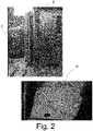
- the method of the present invention are also supplied 6 cold accumulators containing a substance which preferably solidifies at the temperature of chamber 3, as hollow plates containing an eutectic liquid and/or azeotropic with freezing temperature of - 35 °C. Thanks to the high temperature gradient available through the use of a liquefied gas, it is possible to obtain relatively limited freezing times of the batteries. For example, with reference to the test apparatus in figure 2 , and the temperatures indicated above, plates 6 were cooled in about 30 minutes, consuming 140 litres of nitrogen. In particular, the cooling time to obtain the complete cooling of an eutectic plate depends on the size of the eutectic plates and it is possible to check the freezing process by controlling or estimating an amount of thermal energy, i.e.
- the time to complete the process is related to the rate of heat removal and the temperature gradient (AT) in which the eutectic plate is located, compared to the eutectic plate is, compared to the external ambient temperature.
- Accumulators 6, after cooling or phase transition are extracted from the chamber 3 and placed in a transportable insulated transportable chamber 7.
- the figure illustrates an embodiment in which chamber 7 is on board a motorised road vehicle but it is also possible to provide insulated chambers 7 that can be unloaded by hand, for example for medicines, which can be transported in the trunk compartment of vehicles or on bicycles, scooters, etc.
- Figure 3 shows in more detail, according to an embodiment, a sketch 10 of a cooling apparatus covered by the present patent application.
- the cooling apparatus comprises a cooling apparatus comprises a cold generation unit 20 where the cooling fluid is stored, a cold storage unit 30, preferably an insulated chamber 31 also known as a "cell" or chamber as mentioned in the preceding paragraphs and realising a closed volume thermally insulated in such a way as to maintain a controllable temperature on its internal surface which is controllable and lower than the temperature present in the external environment surrounding cell 31 and mobile or fixed; and, finally, a cold utilisation unit 40 configured to connect to the storage unit 30 and designed to be housed in dedicated seats (not illustrated) in transport vehicles.
- cold generation unit 20 comprises a refrigerant storage element, preferably a pressurised tank 21 containing liquid nitrogen; a control and operating unit for the parameters supply of the cooling fluid, preferably a control unit 22 , which by means of temperature and pressure sensors receive values of thermo-physical parameters of cold accumulator 6, e.g. an eutectic plate, and sets the optimal values of nitrogen quantity and/or nitrogen supply time to achieve the best combination of performance of the apparatus; a connection group 23, arranged in series and at the end of the generation unit 20, and finally at least a refrigerant transportation line, preferably a hose or conduit 24, connecting tank 21 to the connection unit 23 and through control unit 22.
- a refrigerant storage element preferably a pressurised tank 21 containing liquid nitrogen
- control unit 22 which by means of temperature and pressure sensors receive values of thermo-physical parameters of cold accumulator 6, e.g. an eutectic plate, and sets the optimal values of nitrogen quantity and/or nitrogen supply time to achieve the best combination of performance of the apparatus
- control unit 22 receives a temperature signal from a sensor in contact with the accumulator 6 and verifies the condition that the temperature of the accumulator reaches the freezing threshold of the liquid contained in the accumulator freezing threshold of the liquid contained in accumulator 6, preferably between -30 and -35 °C. and monitors the pressure value reached by the apparatus, e.g. in duct 24, during the freezing process in order to ensure its safety, i.e. the pressure does not exceed a predetermined maximum value.
- control unit 22 verifies a flow rate or quantity of nitrogen directed towards accumulator 6 and calculates the time required for freezing on the basis of the temperature measured on board accumulator 6 when the latter is loaded into the cell. Or, are a flow rate or quantity of nitrogen delivered from the tank 21 and a tank size, are stored or set21 and an accumulator size, and the time of nitrogen delivery is calculated based on the difference in temperature of the nitrogen with accumulator 6 loaded in the cell.
- the connection unit 23 provides communication between the cold generation unit 20 and storage unit 30, and comprises a control element, preferably a solenoid valve 25 for controlling, through the opening and closing of the passage section of circuit line 24, the flow of line 24 of the circuit, the flow of the refrigerant fluid and to exchange return information with the aid to exchange feedback information with control unit 22 such as a temperature of the accumulator 6 charged in the cell and/or a pressure inside the cell; and a connecting member communicating with solenoid valve 25, preferably a quick multi-connection 26.
- the rapid multi-connection 26 performs the function of a mechanical and fluidic connection between generating unit 20 and generation unit 20 and storage unit 30, fluidic connection, and electrical/electronic connection, with the control unit 22.
- the mechanical connection guarantees the connection and interfacing between multi-connection 26 and cell 31 providing structural continuity between the members of the apparatus of Fig.3 ;
- the fluidic connection function ensures the supply from the reservoir 21 to cell 31, e.g. to accumulator 6 of the thermal flow of refrigerant; and
- the function of electrical connection with control unit 22 allows the programming therefore the control of the thermophysical parameters of the apparatus.
- Storage unit 30 located in a fixed or mobile position, comprises a cell 31 capable of creating a closed and thermally insulated volume to guarantee on its internal surface a temperature lower than the temperature acting on the external surface and corresponding to the ambient temperature; and at least one housing 32 for allowing the engagement and disengagement of rapid multi-connection 27 belonging to the generating unit 20 and the passage of the refrigerant through the wall of said cell 31.
- the housing 32 comprises at least one inlet port 33, preferably cylindrical, preferably passing through a wall of cell 31 which achieves a releasable communication with cold generation unit 20 and comprising an external stop 34 and an internal stop surface 35.
- Outer stop surface 34 preferably cylindrical, is suitable for housing a coupling element, preferably a bushing 36 and the inner stop surface 35 is suitable for housing a sensor, preferably a temperature sensor 38 mechanically positioned in contact with utilization unit 40, and an adapter element, preferably a plug-in terminal block 37, positioned between the eutectic plate 41 (described below) and quick multiconnection 26, making the mechanical connection
- storage unit 30 has a door allowing communication with the external environment and housing a fluid control element, preferably a mechanical air valve 48 for better pressure balancing during the cooling process, between the internal volume of cell 31 and the external environment.
- valve 48 defines a localised pressure drop, e.g. by means of a narrowing of the passage area with respect to a cross-section of coil 46, so as to retain the nitrogen in the coil for a longer period of time and to favour the thermal heat exchange with the same nitrogen consumption.
- Storage unit 30 is designed to engage and disengage with utilisation unit 40; the latter comprises a fluid refrigerant containment element, preferably a eutectic plate 41 having a preferably prismatic and flattened shape, comprising at least one lower connection element 42, preferably cylindrical, which allows the refrigerant fluid to flow inside eutectic plate 41 through the connection with plug terminal 37, and at least one upper connection element 43, preferably cylindrical, which allows the refrigerant fluid to flow inside the eutectic plate 41 one upper connection element 43, preferably cylindrical and comprising a cylindrical and comprising a line portion, preferably a conveyor section 45 which allows the discharge or discharge or escape of the refrigerant from eutectic plate 41 through an eutectic 41 through a closing element, preferably a mechanical valve 44, preferably integral with eutectic plate 41 and mechanically coupled to manifold section 45 and maintaining the fluid inside the eutectic plate 41 until the parameters of pressure and temperature are set by means of the solenoid valve 25.
- eutectic plate 41 has a structure preferably prismatic and realizing an internal volume housing a heat exchange element ((not illustrated in Fig. 3 ) shaped to form a grid, preferably an "S" shaped metal coil 46 (not illustrated in Fig. 3 ) and traversed on the inside by the fluid entering the lower part through the lower connection element 42 and exiting from the eutectic plate 41 in the upper part through the upper connection element 43.
- the internal volume is filled with a eutectic liquid 47 in contact with coil 46.
- the average insertion pressure of the refrigerant inside metallic coil 46 is preferably 4 bar, while it subsequently expands due to the temperature increase until it reaches a value of 20 bar.
- the refrigerant flows along metal coil 46 and exchanges energy with surrounding eutectic liquid 47.
- plate 41 is disconnected from storage unit 30 through plug terminal 37, and housed in sites obtained inside a mobile vehicle for maintaining an internal temperature below than the external temperature of environment during transportation.
- plug 37 is provided with a bayonet connection or similar so that unloaded plate 41, after having been placed in the cell, is fluid-tightly connected to plug 37.
- the excess of refrigerant fluid is basked in the cell 31 and subsequently removed manually or by means of suitable valves for disposal in special plants or dispersed. into the atmosphere without any particular effects, in the case of nitrogen.
- the exhausted liquefied gas exiting device 5 can be can be either recovered through a closed circuit or, in particular if inert and non-toxic, be released into the environment by means of an outlet port 8 appropriately connected to a non-return valve 9 to prevent air from entering device 5.
- the exhausted fluid from device 5 can be used to cool an additional chamber in which the temperature is higher than the temperature of the chamber 3.
- the exhausted fluid exiting device 5 enters a heat exchanger. for cooling additional fluids for various other uses, for example for cooling industrial machinery or for air conditioning circuits for environments intended for animals, plants, or people.
Landscapes
- Engineering & Computer Science (AREA)
- Chemical & Material Sciences (AREA)
- Combustion & Propulsion (AREA)
- Physics & Mathematics (AREA)
- Mechanical Engineering (AREA)
- Thermal Sciences (AREA)
- General Engineering & Computer Science (AREA)
- Control Of Heat Treatment Processes (AREA)
Applications Claiming Priority (1)
| Application Number | Priority Date | Filing Date | Title |
|---|---|---|---|
| IT102021000003623A IT202100003623A1 (it) | 2021-02-17 | 2021-02-17 | Metodo per raffreddare accumulatori e trasportare prodotti in ambiente controllato |
Publications (1)
| Publication Number | Publication Date |
|---|---|
| EP4047291A1 true EP4047291A1 (de) | 2022-08-24 |
Family
ID=75850470
Family Applications (1)
| Application Number | Title | Priority Date | Filing Date |
|---|---|---|---|
| EP21202270.1A Withdrawn EP4047291A1 (de) | 2021-02-17 | 2021-10-12 | Akkumulator-kühlverfahren für artikeltransport in kontrollierter umgebung |
Country Status (2)
| Country | Link |
|---|---|
| EP (1) | EP4047291A1 (de) |
| IT (1) | IT202100003623A1 (de) |
Citations (2)
| Publication number | Priority date | Publication date | Assignee | Title |
|---|---|---|---|---|
| DE19840262A1 (de) * | 1998-09-03 | 2000-03-09 | Messer Griesheim Gmbh | Vorrichtung und Verfahren zum Kühlen eines Behälters |
| EP3051238A1 (de) * | 2015-01-29 | 2016-08-03 | Air Liquide Deutschland GmbH | Kühlbox und Verfahren zum Transport von wärmeempfindlichen Produkten in einem Transportfahrzeug und/oder zum Verteilen von Produkten an Endkunden |
-
2021
- 2021-02-17 IT IT102021000003623A patent/IT202100003623A1/it unknown
- 2021-10-12 EP EP21202270.1A patent/EP4047291A1/de not_active Withdrawn
Patent Citations (2)
| Publication number | Priority date | Publication date | Assignee | Title |
|---|---|---|---|---|
| DE19840262A1 (de) * | 1998-09-03 | 2000-03-09 | Messer Griesheim Gmbh | Vorrichtung und Verfahren zum Kühlen eines Behälters |
| EP3051238A1 (de) * | 2015-01-29 | 2016-08-03 | Air Liquide Deutschland GmbH | Kühlbox und Verfahren zum Transport von wärmeempfindlichen Produkten in einem Transportfahrzeug und/oder zum Verteilen von Produkten an Endkunden |
Also Published As
| Publication number | Publication date |
|---|---|
| IT202100003623A1 (it) | 2022-08-17 |
Similar Documents
| Publication | Publication Date | Title |
|---|---|---|
| CN111183050B (zh) | 运输制冷系统 | |
| US8671997B2 (en) | Device and method for filling a container with a gas under pressure | |
| US20040216469A1 (en) | Environmentally friendly method and apparatus for cooling a temperature controlled space | |
| US20180259230A1 (en) | Portable instant cooling system with controlled temperature obtained through timed-release liquid or gaseous co2 coolant for general refrigeration use in mobile and stationary containers | |
| WO2009024871A2 (en) | High pressure gas tank heat management by circulation of the refueling gas | |
| EP0599638A1 (de) | Klimatisierungs- und Kältevorrichtung unter Verwendung eines Kryogenmittels | |
| EP3218655B1 (de) | Kühlsystem | |
| JP2016512879A (ja) | 携帯型自己冷却自律システム | |
| CN111380325A (zh) | 用于对运输气候控制系统蒸发器节能除霜的方法和系统 | |
| KR100995695B1 (ko) | 보냉차량 | |
| EP3827772B1 (de) | Gefrierausrüstung | |
| CN110254340B (zh) | 用于运送冷藏货物的基于液氮的便携式冷藏系统 | |
| EP3974217B1 (de) | Verfahren und systeme zur aufrechterhaltung der ladung bei einer extrem niedrigen temperatur über einen längeren zeitraum | |
| EP4238793A1 (de) | Wasserstoffgassystem für kombinierte kühlung und leistung | |
| AU682814B2 (en) | Portable self-contained cooler/freezer for use on airplanes,common carrier unrefrigerated trucks | |
| GB2324852A (en) | Controlling the temperature of products during distribution | |
| EP1128139A1 (de) | Kühlsystem für Kühlfahrzeuge | |
| US12276449B2 (en) | Rechargeable thermal battery systems for use in transporting or storing perishable items | |
| CN206989548U (zh) | 分体移动式智能物流急速冷藏设备 | |
| US11747066B2 (en) | Temperature-controlled sorption system | |
| KR100975376B1 (ko) | 이동식 축냉 장치 | |
| CN118970092A (zh) | 一种液氢燃料电池中的冷能分配系统、装置及使用方法 | |
| EP3244144A1 (de) | Isothermischer behälter für den transport von verderblichen nahrungsmitteln | |
| CN114719541A (zh) | 储物装置及制冷设备 | |
| HK1136338A (en) | Refrigerant charge storage |
Legal Events
| Date | Code | Title | Description |
|---|---|---|---|
| PUAI | Public reference made under article 153(3) epc to a published international application that has entered the european phase |
Free format text: ORIGINAL CODE: 0009012 |
|
| STAA | Information on the status of an ep patent application or granted ep patent |
Free format text: STATUS: THE APPLICATION HAS BEEN PUBLISHED |
|
| AK | Designated contracting states |
Kind code of ref document: A1 Designated state(s): AL AT BE BG CH CY CZ DE DK EE ES FI FR GB GR HR HU IE IS IT LI LT LU LV MC MK MT NL NO PL PT RO RS SE SI SK SM TR |
|
| STAA | Information on the status of an ep patent application or granted ep patent |
Free format text: STATUS: THE APPLICATION IS DEEMED TO BE WITHDRAWN |
|
| 18D | Application deemed to be withdrawn |
Effective date: 20230225 |